EP2267438A2 - adhésive-capteur de thermofusibles et adhésifs liquides - Google Patents
adhésive-capteur de thermofusibles et adhésifs liquides Download PDFInfo
- Publication number
- EP2267438A2 EP2267438A2 EP10165943A EP10165943A EP2267438A2 EP 2267438 A2 EP2267438 A2 EP 2267438A2 EP 10165943 A EP10165943 A EP 10165943A EP 10165943 A EP10165943 A EP 10165943A EP 2267438 A2 EP2267438 A2 EP 2267438A2
- Authority
- EP
- European Patent Office
- Prior art keywords
- adhesive
- infrared radiation
- wavelength
- infrared
- sensor
- Prior art date
- Legal status (The legal status is an assumption and is not a legal conclusion. Google has not performed a legal analysis and makes no representation as to the accuracy of the status listed.)
- Withdrawn
Links
- 239000000853 adhesive Substances 0.000 title claims abstract description 149
- 230000001070 adhesive effect Effects 0.000 title claims abstract description 149
- 239000007788 liquid Substances 0.000 title description 25
- 239000012943 hotmelt Substances 0.000 title description 6
- 230000005855 radiation Effects 0.000 claims abstract description 84
- 238000000034 method Methods 0.000 claims abstract description 32
- 230000008685 targeting Effects 0.000 claims abstract description 7
- 239000000758 substrate Substances 0.000 claims description 33
- 238000001228 spectrum Methods 0.000 claims description 10
- 238000012795 verification Methods 0.000 claims description 10
- 230000004044 response Effects 0.000 claims description 6
- 239000000835 fiber Substances 0.000 claims description 4
- 230000001678 irradiating effect Effects 0.000 claims description 2
- 239000004822 Hot adhesive Substances 0.000 abstract description 2
- 239000004831 Hot glue Substances 0.000 description 20
- 238000001514 detection method Methods 0.000 description 12
- 230000008569 process Effects 0.000 description 10
- 239000000463 material Substances 0.000 description 5
- 239000011324 bead Substances 0.000 description 4
- 238000005259 measurement Methods 0.000 description 4
- 229910000530 Gallium indium arsenide Inorganic materials 0.000 description 3
- KXNLCSXBJCPWGL-UHFFFAOYSA-N [Ga].[As].[In] Chemical compound [Ga].[As].[In] KXNLCSXBJCPWGL-UHFFFAOYSA-N 0.000 description 3
- 230000008859 change Effects 0.000 description 3
- 238000012545 processing Methods 0.000 description 3
- 230000008901 benefit Effects 0.000 description 2
- 230000005540 biological transmission Effects 0.000 description 2
- 238000005286 illumination Methods 0.000 description 2
- GYHNNYVSQQEPJS-UHFFFAOYSA-N Gallium Chemical compound [Ga] GYHNNYVSQQEPJS-UHFFFAOYSA-N 0.000 description 1
- 230000009471 action Effects 0.000 description 1
- 229910052785 arsenic Inorganic materials 0.000 description 1
- RQNWIZPPADIBDY-UHFFFAOYSA-N arsenic atom Chemical compound [As] RQNWIZPPADIBDY-UHFFFAOYSA-N 0.000 description 1
- 238000006243 chemical reaction Methods 0.000 description 1
- 238000010276 construction Methods 0.000 description 1
- 230000007423 decrease Effects 0.000 description 1
- 238000013461 design Methods 0.000 description 1
- 230000009977 dual effect Effects 0.000 description 1
- 229910052733 gallium Inorganic materials 0.000 description 1
- 230000006872 improvement Effects 0.000 description 1
- 229910052738 indium Inorganic materials 0.000 description 1
- APFVFJFRJDLVQX-UHFFFAOYSA-N indium atom Chemical compound [In] APFVFJFRJDLVQX-UHFFFAOYSA-N 0.000 description 1
- 238000007689 inspection Methods 0.000 description 1
- 238000012986 modification Methods 0.000 description 1
- 230000004048 modification Effects 0.000 description 1
- 238000012544 monitoring process Methods 0.000 description 1
- 239000013307 optical fiber Substances 0.000 description 1
- 239000004065 semiconductor Substances 0.000 description 1
- 238000000926 separation method Methods 0.000 description 1
- 230000003595 spectral effect Effects 0.000 description 1
- 230000000153 supplemental effect Effects 0.000 description 1
- 238000012800 visualization Methods 0.000 description 1
Images
Classifications
-
- G—PHYSICS
- G01—MEASURING; TESTING
- G01N—INVESTIGATING OR ANALYSING MATERIALS BY DETERMINING THEIR CHEMICAL OR PHYSICAL PROPERTIES
- G01N21/00—Investigating or analysing materials by the use of optical means, i.e. using sub-millimetre waves, infrared, visible or ultraviolet light
- G01N21/84—Systems specially adapted for particular applications
- G01N21/88—Investigating the presence of flaws or contamination
- G01N21/95—Investigating the presence of flaws or contamination characterised by the material or shape of the object to be examined
- G01N21/951—Balls
-
- G—PHYSICS
- G01—MEASURING; TESTING
- G01N—INVESTIGATING OR ANALYSING MATERIALS BY DETERMINING THEIR CHEMICAL OR PHYSICAL PROPERTIES
- G01N21/00—Investigating or analysing materials by the use of optical means, i.e. using sub-millimetre waves, infrared, visible or ultraviolet light
- G01N21/84—Systems specially adapted for particular applications
- G01N21/88—Investigating the presence of flaws or contamination
- G01N21/8806—Specially adapted optical and illumination features
Definitions
- the invention relates to an apparatus for on-line detection and measurement of liquid adhesives and hot melt adhesives applied to a substrate using the same near infrared detector.
- an apparatus for detecting a first adhesive.
- the apparatus includes first and second radiation sources configured to direct near-infrared radiation at respective first and second wavelengths toward an amount of the first adhesive on a substrate.
- the apparatus further includes an adhesive sensor configured to sense the near-infrared radiation at the first and second wavelengths.
- the adhesive sensor is further configured to collect portions of the near-infrared radiation that are reflected from the amount of the first adhesive on the substrate and to generate respective first and second signals.
- the adhesive sensor may include a photodiode configured to detect near-infrared radiation thermally emitted from a second adhesive on the substrate without the use of the first and second radiation sources.
- the first and second radiation sources may be near infrared photodiodes configured to emit radiation in the near-infrared band of the electromagnetic spectrum.
- the apparatus may also include a visible light source configured for use in targeting and focusing the adhesive sensor.
- the first wavelength may be about 1,260 nm and the second wavelength may be about 1,440 nm.
- the first and second wavelengths are selected within the near-infrared band of the electromagnetic spectrum such that the first adhesive has different reflection coefficients at the first and second wavelengths.
- the first and second radiation sources are near infrared photodiodes configured to emit radiation in the near-infrared band of the electromagnetic spectrum
- the apparatus further includes a microprocessor configured to receive signals from the adhesive sensor and to drive the first and second near infrared photodiodes.
- the microprocessor may be further configured to determine presence or absence of the adhesive on the substrate based upon a comparison of the portion of the near-infrared radiation at the first wavelength collected by the adhesive sensor and the portion of the near-infrared radiation at the second wavelength collected by the adhesive sensor.
- the adhesive sensor may include a photodiode configured to detect near-infrared radiation at the first and second wavelengths
- the apparatus may further include a signal output electrically connecting the microprocessor with a verification system, an amplifier electrically connected with the photodiode, and an analog to digital converter electrically connecting the amplifier with the microprocessor, wherein the amplifier is configured to amplify signals produced by the photodiode in response to collecting and sensing the first and second portions of the near-infrared radiation at the first and second wavelengths, and the analog to digital converter is configured to convert the amplified signals from the photodiode to digital signals supplied to the microprocessor.
- the adhesive sensor is configured to collect and sense the near-infrared radiation at the first and second wavelengths without the use of a fiber optic element.
- a method for sensing first and second adhesives applied to a substrate.
- the method includes sensing near-infrared radiation thermally emitted from the first adhesive and sensing near-infrared radiation at a first wavelength reflected from the second adhesive.
- the near-infrared radiation at the first wavelength reflected from the second adhesive may be sensed by irradiating the second adhesive with the near-infrared radiation at the first wavelength and collecting a portion of the near-infrared radiation at the first wavelength that is reflected from the second adhesive.
- the method may further include collecting a portion of near-infrared radiation at a second wavelength that is reflected from the second adhesive and comparing the portion of the near-infrared radiation at the first wavelength with the portion of the near-infrared radiation at the second wavelength to determine the presence or absence of the second adhesive on the substrate.
- the presence or absence of the second adhesive on the substrate may be communicated to a verification system.
- the adhesive may be sequentially illuminated with the near-infrared radiation at the first and second wavelengths.
- the first and second wavelengths may be about 1,260 nm and about 1,440 nm, respectively, or the first and second wavelengths may be selected within the near-infrared band of the electromagnetic spectrum such that the first adhesive has different reflection coefficients at the first and second wavelengths.
- first and second adhesives are applied to the substrate at different temperatures and the first adhesive is hotter at the time of application than the second adhesive.
- the near-infrared radiation is sensed by a photodiode of an adhesive sensor, and the method further includes targeting and focusing the adhesive sensor with visible light originating from a visible light source.
- the near-infrared radiation is collected and sensed to practice the method without the use of a fiber optic element.
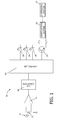
- FIG. 1 is a diagrammatic representation of an adhesive sensor consistent with embodiments of the invention.
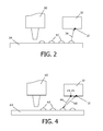
- FIG. 2 is a diagrammatic representation of the adhesive sensor of FIG. 1 detecting a hot melt adhesive.
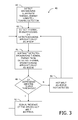
- FIG. 3 is a flowchart of the process for detecting the hot melt adhesive in FIG. 2
- FIG. 4 is a diagrammatic representation of the adhesive sensor of FIG. 1 detecting an aqueous liquid adhesive.
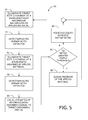
- FIG. 5 is a flowchart of the process for detecting the aqueous liquid adhesive in FIG. 4 .
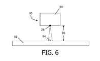
- FIG. 6 is a diagrammatic representation of the adhesive sensor being positioned for use.
- a single near infrared detector sensitive to infrared radiation at different wavelengths may be used in an adhesive sensor to detect both hot melt and liquid adhesives.
- the adhesive sensor may sense infrared radiation thermally emitted from a hot melt adhesive.
- the adhesive sensor may sense infrared radiation from first and second near infrared diodes that emit at different wavelengths that are reflected with different intensities from an adhesive that is at a temperature insufficient to emit infrared radiation at an intensity to be readily detectable.
- the detection methodology detailed below may also provide an increase in detection speed in the sensor (from tens of milliseconds in contemporary sensors to hundreds of microseconds for embodiments of the invention). The increased response time may allow for inspections of smaller targets (dots or breaks in beads) at considerably higher speed.
- visible illumination may be added for targeting of the applied material.
- a single photodiode such as a near infrared (NIR) detector 12 may be used to detect thermal or infrared energy 14 emanating from or emitted by a source of hot melt adhesive or infrared energy 14 being reflected off of a substrate or liquid adhesive on the substrate.
- NIR near infrared
- incident infrared energy 14 is focused on the detector 12 via collection optics.
- the collection optics may consist of a lens assembly configured to collect and focus incident near infrared radiation onto the detector 12.
- the detector 12 converts the thermal energy contained in the infrared radiation into a current, which has a magnitude proportional to the temperature of the source of the infrared radiation.
- the conversion process in the detector 12 is understood by a person having ordinary skill in the art.
- the detector 12 is an Indium Gallium Arsenide (InGaAs) photodiode configured to operate in a near-infrared spectral range of 0.7 ⁇ m to 2.6 ⁇ m.
- InGaAs photodiode include an active semiconductor layer composed of indium, gallium, and arsenic with a composition and construction that reacts to reacts to NIR radiation by generating electron-hole pairs along the photon tracks through the detector 12.
- the energy detected is then amplified by an amplifier 16, converted to digital by an A/D converter 18 and supplied to a controller in the representative form of a microprocessor 20.
- the amplifier 16 is electrically connected to the photodiode to amplify signals produced by the detector 12.
- the A/D converter 18 is electrically connected to the amplifier 16 and converts the amplified signals to digital signals.
- the microprocessor 20 is configured to receive the digital signals representing the measured values from the detector 12, and to use an appropriate algorithm to determine the presence of adhesive dispensed onto the substrate. Depending on the type of adhesive being sensed, the microprocessor 20 manipulates the detected energy and compares that value to a threshold value.
- a signal indicating the presence of an adhesive is transmitted through a transistor 22, which is electrically connected to the microprocessor 20, to a verification system 25 for further processing.
- the verification system 25 monitors the placement of the adhesive on the substrate and can generate an action, such as an alarm, an alarm signal, or display an alarm, if the placement of the adhesive is improper. If the detected energy is below a threshold value, then no signal is transmitted.
- an action such as an alarm, an alarm signal, or display an alarm
- the verification system 25 may optionally communicate an indication of the presence or absence of adhesive to a dispensing system 27. This permits closed loop application of the adhesive by the dispensing system 27 in coordination with feedback from the verification system 25 monitoring the measurements output from adhesive sensor 10.
- the verification and dispensing systems 25, 27 may be integrated into an integrated pattern control and verification system.
- the microprocessor 20 When detecting an aqueous liquid adhesive, the microprocessor 20 selectively illuminates near infrared (“NIR”) radiation sources, such as light emitting diodes (LEDs), each producing photons with energies at different discrete frequencies or wavelengths within the IR wavelength band of the electromagnetic spectrum.
- NIR near infrared
- the microprocessor 20 may illuminate a first NIR radiation source 24, which may be set to emit or transmit infrared energy 14 at a wavelength not absorbed by the substrate or the adhesive (approximately 1,260 nm, for example).
- the microprocessor 20 may illuminate a second NIR radiation source 26, which may be set to emit or transmit infrared energy 14 at a wavelength that is at least partially absorbed by the adhesive material (approximately 1,440 nm, for example) and reflected.
- the microprocessor 20 drives the first and second NIR radiation sources 24, 26, if needed to detect the adhesive.
- the adhesive sensor 10 may also use an additional light source 28, such as a visible LED, in order to target and focus the adhesive sensor 10 with the adhesive application.
- Light source 28 emits light within the visible wavelength band of the electromagnetic spectrum, which has a shorter wavelength than the NIR emitted from the NIR radiation sources 24, 26. Visible light from the light source 28, which is within the response of the human eye, may be used to both align the adhesive sensor 10 with the target adhesive track, as well as to adjust the height of the detector 12 for optimum detection and speed.
- the adhesive sensor 10 may be integrated into any of the GD200 family of devices that are commercially available from Nordson Corporation (Westlake, Ohio) in order to provide the dual capability of detecting hot melt adhesives in addition to detecting liquid adhesives.
- Liquid adhesives which may be aqueous, are typically at or near room temperature and, in any event, emit significantly less infrared radiation than hot melt adhesives.
- the liquid adhesives can be detected using the adhesive sensor 10 in conjunction with the NIR radiation sources 24, 26 to provide supplemental infrared illumination.
- a dispenser 30 may deposit dots or beads of a hot melt adhesive 32 onto a substrate 34.
- the adhesive sensor 10 is positioned and oriented such that the hot melt adhesive 32 deposited on the substrate 34 is within the field of view of the adhesive sensor 10.
- Infrared radiation 36 emanating from the hot melt adhesive 32 as emitted thermal energy may be detected by the detector 12 of adhesive sensor 10 as the substrate 34 passes by the dispenser 30 and adhesive sensor 10. The separation of the detector 12 from the substrate 34 is selected to lie within the detection range of the detector 12.
- FIG. 3 is a flowchart 40 detailing the detection process consistent with an embodiment of the invention.
- the thermal energy associated with the background and substrate 34 is detected by the detector 12 (block 42).
- the detector 12 detects the thermal energy resulting from the application of the hot melt adhesive 32 (block 44).
- the microprocessor 20 uses the baseline thermal energy and the thermal energy detected during the application of the adhesive to determine a change in temperature (block 46). If this change in temperature is less than a threshold value ("No" branch of decision block 48), then no hot melt adhesive 32 is detected (block 50) and the process continues at block 44 by detecting new infrared energy 14 4 from the application of the adhesive.
- a signal is transmitted indicating the presence of hot melt material (block 52). After the transmission of the signal, the process continues at block 44.
- Use of the detector 12 to detect the presence of hot melt adhesive 32 decreases the response time resulting from contemporary thermopiles, allowing for the detection of smaller dots and beads of hot melt adhesive 32 as set forth above and for faster processing speeds.
- Embodiments of the adhesive sensor 10 improve upon this methodology by being able to eliminate the optical fiber transmission system common to conventional sensor architectures, to utilize NIR LEDs, and to only require the use of one detector, namely detector 12.
- a dispenser 60 may deposit dots or beads of a liquid adhesive 62 onto a substrate 64.
- the adhesive sensor 10 may then alternately direct infrared energy 66 from the two NIR LEDs 24, 26 and measure the reflected energy 68 at each wavelength with the detector 12 to determine if liquid adhesive 62 is present.
- FIG. 5 is a flowchart 70 detailing the process of detecting a liquid adhesive 62 according to an embodiment of the invention.
- the microprocessor 20 illuminates a target area with infrared radiation or energy 14 from NIR radiation source 24 at a near infrared wavelength that is not significantly absorbed by either the background or the adhesive (block 72).
- the reflected energy is collected and detected as a baseline signal or value (block 74), and is stored for later processing.
- the microprocessor 20 causes the target area to be illuminated with infrared radiation or energy 14 from NIR radiation source 26 at a near infrared wavelength that is at least partially absorbed by the applied material (i.e., an amount of the liquid adhesive 62). A portion of this energy is also at least partially reflected back toward the sensor 10 for collection and detection as a targeted signal or value (block 78).
- a ratio of the first reference signal (baseline) to the second reference signal (target signal) is calculated for a comparison of the degree of reflection at the two different wavelengths (block 80). If ratio does not exceed a threshold value ("No" branch of decision block 82), liquid adhesive 62 was not detected (block 84) and the process continues at block 72. If the ratio does exceed a threshold, similar to that in U.S. Patent No. 6,281,500 , incorporated by reference above, then a signal is generated in response indicating that liquid adhesive 62 has been detected (block 86). The process then continues at block 72.
- the sensor configuration in FIG. 1 and utilized in FIGS. 4-5 provide an improvement over contemporary liquid adhesive sensors, by providing a fiberless sensor having a single detector resulting in a lower cost solution for a manufacturer.
- the difference in reflection at the two different near infrared wavelengths permit a comparison that can determine the presence or non-presence of liquid adhesive 62.
- the visible light source 28 ( FIG. 1 ) of the adhesive sensor 10 may include lasers, or visible LEDs that can be focused and/or lensed.
- the light source 28 is used to target and focus the head 90 of adhesive sensor 10.
- a visible circular spot 94 is imaged.
- the circular spot 94 is illuminated as a sharply imaged visible circle. Moving farther or closer away from the focal point causes the spot 94 to blur. This aid may be used to align the adhesive sensor 10 with applied materials and fixture the sensor head 90 at the proper height over the target and substrate 92.
- One of ordinary skill in the art will appreciate that there are other methods for determining proper height.
- the apparatus includes an adhesive sensor having a photodiode sensitive to infrared radiation at different wavelengths.
- the adhesive sensor may sense infrared radiation thermally emitted from a sufficiently hot adhesive.
- the adhesive sensor may sense infrared radiation from first and second near infrared diodes that emit at different wavelengths that are reflected with different intensities from an adhesive that is at a temperature insufficient to emit infrared radiation at an intensity to be readily detectable.
- a visible light source may be provided for targeting and focusing the adhesive sensor.
- the adhesive sensor 10 has been illustrated in embodiments including only hot melt adhesives or only liquid adhesives.
- Other embodiments of the invention may include adhesive lines that apply both a hot melt as well as a liquid adhesive and the adhesive sensor 10 will be able to detect either the hot melt adhesive, liquid adhesive, or both, eliminating the need to have multiple sensors within the dispenser. Additional advantages and modifications will readily appear to those skilled in the art.
- the invention in its broader aspects is therefore not limited to the specific details, representative apparatus and method, and illustrative examples shown and described. Accordingly, departures may be made from such details without departing from the scope of the general inventive concept.
Landscapes
- Physics & Mathematics (AREA)
- Health & Medical Sciences (AREA)
- Life Sciences & Earth Sciences (AREA)
- Chemical & Material Sciences (AREA)
- Analytical Chemistry (AREA)
- Biochemistry (AREA)
- General Health & Medical Sciences (AREA)
- General Physics & Mathematics (AREA)
- Immunology (AREA)
- Pathology (AREA)
- Coating Apparatus (AREA)
- Investigating Or Analysing Materials By Optical Means (AREA)
- Investigating Or Analyzing Materials Using Thermal Means (AREA)
Applications Claiming Priority (2)
| Application Number | Priority Date | Filing Date | Title |
|---|---|---|---|
| US21973809P | 2009-06-23 | 2009-06-23 | |
| US12/813,762 US20100320386A1 (en) | 2009-06-23 | 2010-06-11 | Adhesive Sensor for Hot Melt and Liquid Adhesives |
Publications (1)
| Publication Number | Publication Date |
|---|---|
| EP2267438A2 true EP2267438A2 (fr) | 2010-12-29 |
Family
ID=42272728
Family Applications (1)
| Application Number | Title | Priority Date | Filing Date |
|---|---|---|---|
| EP10165943A Withdrawn EP2267438A2 (fr) | 2009-06-23 | 2010-06-15 | adhésive-capteur de thermofusibles et adhésifs liquides |
Country Status (3)
| Country | Link |
|---|---|
| US (1) | US20100320386A1 (fr) |
| EP (1) | EP2267438A2 (fr) |
| JP (1) | JP2011007790A (fr) |
Families Citing this family (5)
| Publication number | Priority date | Publication date | Assignee | Title |
|---|---|---|---|---|
| JP4834981B2 (ja) * | 2004-12-03 | 2011-12-14 | 大日本印刷株式会社 | パターン形成体の製造方法 |
| US8875652B2 (en) * | 2011-09-14 | 2014-11-04 | Apple Inc. | Liquid adhesive boundary control |
| US9645092B2 (en) | 2013-10-14 | 2017-05-09 | Valco Cincinnati, Inc. | Device and method for verifying the construction of adhesively-attached substrates |
| JP2018084550A (ja) * | 2016-11-25 | 2018-05-31 | 株式会社ニレコ | 糊付け検査装置 |
| CN114244365A (zh) * | 2021-12-22 | 2022-03-25 | 海南聚能科技创新研究院有限公司 | 一种全波段近红外传感器 |
Citations (1)
| Publication number | Priority date | Publication date | Assignee | Title |
|---|---|---|---|---|
| US6281500B1 (en) | 1998-12-17 | 2001-08-28 | Nordson Corporation | Detection and measurement of cold emulsion adhesives applied to a substrate |
Family Cites Families (7)
| Publication number | Priority date | Publication date | Assignee | Title |
|---|---|---|---|---|
| US5894126A (en) * | 1996-08-02 | 1999-04-13 | Exergen Corporation | Fast response radiation detector |
| JP2002168776A (ja) * | 2000-12-01 | 2002-06-14 | Advantest Corp | 環境モニタ方法及び装置並びに半導体製造装置 |
| EP1520514A1 (fr) * | 2003-10-02 | 2005-04-06 | Matsushita Electric Industrial Co., Ltd. | Procède et instrument de mesure optique d'informations biologiques |
| US7841533B2 (en) * | 2003-11-13 | 2010-11-30 | Metrologic Instruments, Inc. | Method of capturing and processing digital images of an object within the field of view (FOV) of a hand-supportable digitial image capture and processing system |
| US7462377B2 (en) * | 2004-04-30 | 2008-12-09 | Nordson Corporation | Methods for regulating the placement of fluid dispensed from an applicator onto a workpiece |
| US7365854B2 (en) * | 2004-05-11 | 2008-04-29 | Nordson Corporation | Apparatus and methods for high speed RGB color discrimination |
| US20070179365A1 (en) * | 2006-01-31 | 2007-08-02 | Glucon Inc. | Method for monitoring body fluids |
-
2010
- 2010-06-11 US US12/813,762 patent/US20100320386A1/en not_active Abandoned
- 2010-06-15 EP EP10165943A patent/EP2267438A2/fr not_active Withdrawn
- 2010-06-23 JP JP2010142428A patent/JP2011007790A/ja active Pending
Patent Citations (1)
| Publication number | Priority date | Publication date | Assignee | Title |
|---|---|---|---|---|
| US6281500B1 (en) | 1998-12-17 | 2001-08-28 | Nordson Corporation | Detection and measurement of cold emulsion adhesives applied to a substrate |
Also Published As
| Publication number | Publication date |
|---|---|
| US20100320386A1 (en) | 2010-12-23 |
| JP2011007790A (ja) | 2011-01-13 |
Similar Documents
| Publication | Publication Date | Title |
|---|---|---|
| US20150241347A1 (en) | Nondispersive infrared micro-optics sensor for blood alcohol concentration measurements | |
| EP2267438A2 (fr) | adhésive-capteur de thermofusibles et adhésifs liquides | |
| US8810778B2 (en) | Sensor and method for optically measuring a distance, a position, and/or a profile | |
| NL2018484B1 (en) | Method and device determining soiling of a shield | |
| ATE432518T1 (de) | Branderkennungsverfahren und brandmelder zu dessen durchführung | |
| JP2018524073A5 (fr) | ||
| CN105954227B (zh) | 铝塑板泡罩包装药品的太赫兹监测方法 | |
| FI124966B (fi) | Silmämittari ja menetelmä silmän mittaamiseksi | |
| WO2009102089A1 (fr) | Appareil pour mesurer une épaisseur | |
| EP2543316B1 (fr) | Appareil permettant de mesurer la luminance et la température d'une source de lumière d'un dispositif spectrophotométrique | |
| US8496375B2 (en) | Pyrometer adapted for detecting UV-radiation and use thereof | |
| CN106659406A (zh) | 使用环境光收集器监测生物计量参数的装置和方法 | |
| FI3758606T3 (fi) | Menetelmä valonlähteen intensiteetin valitsemiseksi veressä olevan analyytin seuraamiseksi ja laite sitä varten | |
| CN106413513B (zh) | 曲率传感器、内窥镜装置 | |
| EP0795743A3 (fr) | Procédé et appareil de mesure de l'humidité dans l'infrarouge | |
| JP3547968B2 (ja) | 脈拍波形検出装置 | |
| US6118107A (en) | Process and device for in-service measurement of temperature in at least one cooking zone of a cooking area with a glass ceramic plate | |
| US20170038249A1 (en) | Optical processing head and 3d shaping apparatus | |
| JP6342445B2 (ja) | 光学計測デバイス及びその方法 | |
| CN111150401A (zh) | 一种利用探测出射光强测量组织厚度的方法 | |
| CN102564732B (zh) | 一种核聚变装置光学窗口透过率测量装置 | |
| US9640682B2 (en) | Device for emitting electromagnetic radiation | |
| JPH1137930A (ja) | 吸光光度計 | |
| US9993158B2 (en) | Apparatus for measuring condition of object | |
| JP2003210497A (ja) | 歯垢の検査装置 |
Legal Events
| Date | Code | Title | Description |
|---|---|---|---|
| PUAI | Public reference made under article 153(3) epc to a published international application that has entered the european phase |
Free format text: ORIGINAL CODE: 0009012 |
|
| AK | Designated contracting states |
Kind code of ref document: A2 Designated state(s): AL AT BE BG CH CY CZ DE DK EE ES FI FR GB GR HR HU IE IS IT LI LT LU LV MC MK MT NL NO PL PT RO SE SI SK SM TR |
|
| AX | Request for extension of the european patent |
Extension state: BA ME RS |
|
| STAA | Information on the status of an ep patent application or granted ep patent |
Free format text: STATUS: THE APPLICATION IS DEEMED TO BE WITHDRAWN |
|
| 18D | Application deemed to be withdrawn |
Effective date: 20130103 |