EP2273300B1 - Microscope avec un sens de l'observation pèrpendiculaire au sens de l'éclairage et une méthode d'inspection microscopique - Google Patents
Microscope avec un sens de l'observation pèrpendiculaire au sens de l'éclairage et une méthode d'inspection microscopique Download PDFInfo
- Publication number
- EP2273300B1 EP2273300B1 EP10183679.9A EP10183679A EP2273300B1 EP 2273300 B1 EP2273300 B1 EP 2273300B1 EP 10183679 A EP10183679 A EP 10183679A EP 2273300 B1 EP2273300 B1 EP 2273300B1
- Authority
- EP
- European Patent Office
- Prior art keywords
- illumination
- microscope
- beam path
- detection
- sample
- Prior art date
- Legal status (The legal status is an assumption and is not a legal conclusion. Google has not performed a legal analysis and makes no representation as to the accuracy of the status listed.)
- Expired - Lifetime
Links
- 238000005286 illumination Methods 0.000 title claims abstract description 163
- 238000000034 method Methods 0.000 title claims description 7
- 238000007689 inspection Methods 0.000 title 1
- 238000001514 detection method Methods 0.000 claims abstract description 82
- 230000003287 optical effect Effects 0.000 claims description 15
- 238000003384 imaging method Methods 0.000 claims description 7
- 230000005484 gravity Effects 0.000 claims description 5
- 238000005070 sampling Methods 0.000 claims 2
- 239000000523 sample Substances 0.000 description 73
- 239000002245 particle Substances 0.000 description 5
- 230000008901 benefit Effects 0.000 description 3
- 230000005284 excitation Effects 0.000 description 3
- 230000006978 adaptation Effects 0.000 description 2
- 230000000712 assembly Effects 0.000 description 2
- 238000000429 assembly Methods 0.000 description 2
- 239000012472 biological sample Substances 0.000 description 2
- 230000008859 change Effects 0.000 description 2
- 238000010586 diagram Methods 0.000 description 2
- 238000006073 displacement reaction Methods 0.000 description 2
- 230000014509 gene expression Effects 0.000 description 2
- 239000007788 liquid Substances 0.000 description 2
- 238000005259 measurement Methods 0.000 description 2
- 238000012986 modification Methods 0.000 description 2
- 230000004048 modification Effects 0.000 description 2
- 230000008569 process Effects 0.000 description 2
- 238000011160 research Methods 0.000 description 2
- 238000003325 tomography Methods 0.000 description 2
- 230000007704 transition Effects 0.000 description 2
- XLYOFNOQVPJJNP-UHFFFAOYSA-N water Substances O XLYOFNOQVPJJNP-UHFFFAOYSA-N 0.000 description 2
- TVEXGJYMHHTVKP-UHFFFAOYSA-N 6-oxabicyclo[3.2.1]oct-3-en-7-one Chemical compound C1C2C(=O)OC1C=CC2 TVEXGJYMHHTVKP-UHFFFAOYSA-N 0.000 description 1
- 241000894006 Bacteria Species 0.000 description 1
- 241000197194 Bulla Species 0.000 description 1
- 241000700199 Cavia porcellus Species 0.000 description 1
- 238000010521 absorption reaction Methods 0.000 description 1
- 238000013459 approach Methods 0.000 description 1
- 238000000149 argon plasma sintering Methods 0.000 description 1
- 230000005540 biological transmission Effects 0.000 description 1
- 208000002352 blister Diseases 0.000 description 1
- 230000000295 complement effect Effects 0.000 description 1
- 238000004624 confocal microscopy Methods 0.000 description 1
- 238000010276 construction Methods 0.000 description 1
- 238000004132 cross linking Methods 0.000 description 1
- 230000003247 decreasing effect Effects 0.000 description 1
- 230000006735 deficit Effects 0.000 description 1
- 230000001419 dependent effect Effects 0.000 description 1
- 230000001066 destructive effect Effects 0.000 description 1
- 210000002257 embryonic structure Anatomy 0.000 description 1
- 238000010195 expression analysis Methods 0.000 description 1
- 238000000684 flow cytometry Methods 0.000 description 1
- 230000006870 function Effects 0.000 description 1
- 239000011521 glass Substances 0.000 description 1
- 238000013507 mapping Methods 0.000 description 1
- 239000013307 optical fiber Substances 0.000 description 1
- 230000035699 permeability Effects 0.000 description 1
- 230000000379 polymerizing effect Effects 0.000 description 1
- 238000012545 processing Methods 0.000 description 1
- 238000001454 recorded image Methods 0.000 description 1
- 238000012552 review Methods 0.000 description 1
- 238000000926 separation method Methods 0.000 description 1
- 239000013589 supplement Substances 0.000 description 1
- 238000012546 transfer Methods 0.000 description 1
Images
Classifications
-
- G—PHYSICS
- G02—OPTICS
- G02B—OPTICAL ELEMENTS, SYSTEMS OR APPARATUS
- G02B21/00—Microscopes
- G02B21/0004—Microscopes specially adapted for specific applications
- G02B21/002—Scanning microscopes
- G02B21/0024—Confocal scanning microscopes (CSOMs) or confocal "macroscopes"; Accessories which are not restricted to use with CSOMs, e.g. sample holders
- G02B21/0032—Optical details of illumination, e.g. light-sources, pinholes, beam splitters, slits, fibers
-
- G—PHYSICS
- G01—MEASURING; TESTING
- G01N—INVESTIGATING OR ANALYSING MATERIALS BY DETERMINING THEIR CHEMICAL OR PHYSICAL PROPERTIES
- G01N21/00—Investigating or analysing materials by the use of optical means, i.e. using sub-millimetre waves, infrared, visible or ultraviolet light
- G01N21/17—Systems in which incident light is modified in accordance with the properties of the material investigated
- G01N21/47—Scattering, i.e. diffuse reflection
- G01N21/4795—Scattering, i.e. diffuse reflection spatially resolved investigating of object in scattering medium
-
- G—PHYSICS
- G01—MEASURING; TESTING
- G01N—INVESTIGATING OR ANALYSING MATERIALS BY DETERMINING THEIR CHEMICAL OR PHYSICAL PROPERTIES
- G01N21/00—Investigating or analysing materials by the use of optical means, i.e. using sub-millimetre waves, infrared, visible or ultraviolet light
- G01N21/62—Systems in which the material investigated is excited whereby it emits light or causes a change in wavelength of the incident light
- G01N21/63—Systems in which the material investigated is excited whereby it emits light or causes a change in wavelength of the incident light optically excited
- G01N21/64—Fluorescence; Phosphorescence
- G01N21/645—Specially adapted constructive features of fluorimeters
- G01N21/6456—Spatial resolved fluorescence measurements; Imaging
- G01N21/6458—Fluorescence microscopy
-
- G—PHYSICS
- G02—OPTICS
- G02B—OPTICAL ELEMENTS, SYSTEMS OR APPARATUS
- G02B21/00—Microscopes
- G02B21/0004—Microscopes specially adapted for specific applications
- G02B21/002—Scanning microscopes
- G02B21/0024—Confocal scanning microscopes (CSOMs) or confocal "macroscopes"; Accessories which are not restricted to use with CSOMs, e.g. sample holders
- G02B21/0036—Scanning details, e.g. scanning stages
- G02B21/0048—Scanning details, e.g. scanning stages scanning mirrors, e.g. rotating or galvanomirrors, MEMS mirrors
-
- G—PHYSICS
- G02—OPTICS
- G02B—OPTICAL ELEMENTS, SYSTEMS OR APPARATUS
- G02B21/00—Microscopes
- G02B21/0004—Microscopes specially adapted for specific applications
- G02B21/002—Scanning microscopes
- G02B21/0024—Confocal scanning microscopes (CSOMs) or confocal "macroscopes"; Accessories which are not restricted to use with CSOMs, e.g. sample holders
- G02B21/0052—Optical details of the image generation
- G02B21/0056—Optical details of the image generation based on optical coherence, e.g. phase-contrast arrangements, interference arrangements
-
- G—PHYSICS
- G02—OPTICS
- G02B—OPTICAL ELEMENTS, SYSTEMS OR APPARATUS
- G02B21/00—Microscopes
- G02B21/0004—Microscopes specially adapted for specific applications
- G02B21/002—Scanning microscopes
- G02B21/0024—Confocal scanning microscopes (CSOMs) or confocal "macroscopes"; Accessories which are not restricted to use with CSOMs, e.g. sample holders
- G02B21/0052—Optical details of the image generation
- G02B21/0076—Optical details of the image generation arrangements using fluorescence or luminescence
-
- G—PHYSICS
- G02—OPTICS
- G02B—OPTICAL ELEMENTS, SYSTEMS OR APPARATUS
- G02B21/00—Microscopes
- G02B21/06—Means for illuminating specimens
-
- G—PHYSICS
- G02—OPTICS
- G02B—OPTICAL ELEMENTS, SYSTEMS OR APPARATUS
- G02B21/00—Microscopes
- G02B21/16—Microscopes adapted for ultraviolet illumination ; Fluorescence microscopes
-
- G—PHYSICS
- G02—OPTICS
- G02B—OPTICAL ELEMENTS, SYSTEMS OR APPARATUS
- G02B21/00—Microscopes
- G02B21/24—Base structure
- G02B21/26—Stages; Adjusting means therefor
-
- G—PHYSICS
- G02—OPTICS
- G02B—OPTICAL ELEMENTS, SYSTEMS OR APPARATUS
- G02B21/00—Microscopes
- G02B21/36—Microscopes arranged for photographic purposes or projection purposes or digital imaging or video purposes including associated control and data processing arrangements
- G02B21/365—Control or image processing arrangements for digital or video microscopes
- G02B21/367—Control or image processing arrangements for digital or video microscopes providing an output produced by processing a plurality of individual source images, e.g. image tiling, montage, composite images, depth sectioning, image comparison
Definitions
- the present invention relates to a microscope according to the preamble of claim 1.
- a microscope for oceanographic research is known from the scientific literature, which is characterized in that it uses a laser to generate an illumination light plane in a sample chamber and, perpendicular to this plane, detects the fluorescence signals generated in the illumination light plane with a camera [ E. Fuchs et al., Opt. Express 10.145 (2002 )].
- This microscope is similar to the ultramicroscope from H. Siedentopf and R. Zsigmondy [Ann. Phys. 10 (4), 1 (1903 )] and is used for the detection of individual free-floating particles such as bacteria. It is not suitable for taking millimeter-sized samples, for example developmental biology, as a cuvette serves as a sample holder.
- Optical projection tomography is used, for example, in gene expression analysis [ J. Sharpe et al., Science 296,541 (2002 )].
- This is a system in which projections of biological samples are recorded, with the sample being rotated around an axis perpendicular to the detection direction. Since the sample is not selectively illuminated perpendicular to the detection axis by an illumination light plane, the microscope, in contrast to the microscope according to the invention, has a very large depth of field through which a large part of the sample is captured. Therefore, the microscope does not offer the possibility of moving the sample along the detection axis in order to record a three-dimensional image. A three-dimensional image of the sample with spatial resolution is therefore only possible through the reconstruction from the projections.
- a confocal theta microscope which is characterized in that it uses a first objective for point illumination and a second objective for imaging the object light onto a point detector, the detection direction being approximately perpendicular to the illumination direction.
- the confocal area of overlap between the illumination volume and the detection volume is particularly small and the microscope achieves an almost isotropic resolution, the order of magnitude of which corresponds to the lateral resolution of a confocal microscope.
- theta microscope is arranged confocally, which places high demands on the relative adjustment of the illumination and detection focus.
- it is not easily able to take pictures of large objects. This is because the object in the theta microscope does not have enough freedom of movement when the object is scanned and because of the point detection it has to be scanned in three directions, which means that an exposure takes a very long time.
- the illumination light is focused to an illumination point.
- the object on which the present invention is based is to propose a microscope that is suitable for high-resolution, three-dimensional observation of millimeter-sized biological objects, with rapid recording of the data being possible and the construction being technically as simple as possible.
- This object is achieved according to the invention by the microscope specified in claim 1.
- the sample is illuminated by a thin line-like light strip and the observation takes place perpendicular to this object illumination area, which has a ray-like or line-like extension.
- the thickness of the illuminating light strip thus largely determines the depth of field of the system.
- the object is used for image acquisition moves the spatially fixed light strip, and fluorescence and / or scattered light are recorded in each position of the grid movement with a flat detector in elongated areas. Since the object can be rotated in the preferred embodiment, it is possible to take such three-dimensional recordings from several sides and combine them into a single three-dimensional record, the resolution of which is essentially is determined by the lateral resolution of the individual recordings.
- the high resolution of this image is the result of the focused lighting, the vertical detection, the movement of the object and the combination of the individual images through image processing.
- the microscope according to the invention has an illumination light path and a detection light path which are preferably orthogonal to one another in the object illumination area, whereby the detection direction is perpendicular to the illumination light plane.
- the advantages of the invention are still achieved to a sufficient extent when the angle between the illumination direction and the detection direction or between the illumination light plane and the detection direction does not deviate from a right angle to a great extent.
- a laser which enables the selective excitation of fluorescence emission in the sample is advantageously used as the light source.
- a cylindrical lens is preferably used to focus the illuminating light into a thin strip, but another focusing element (for example a holographic element or a conical lens (axicon) or a phase plate or other elements for generating a Bessel beam) can also be used.
- the detected light is preferably fluorescent light. However, it is also possible to detect scattered light.
- the detection light is preferably imaged on the elongated areas of the detector using a telecentric system made up of two lenses. However, other optical assemblies are also suitable.
- the detection is preferably carried out with a flat detector that detects the entire field, for example a CCD camera.
- a CCD camera enables rapid image recording and the movement of the sample for a three-dimensional recording is restricted to one direction (namely along the detection axis).
- the resolution of the system is determined by the lateral resolution of the detection optics.
- the area of the currently available detectors is generally not sufficient to ensure a complete, high-resolution image of objects several millimeters in size
- no optical elements are used to guide the beam paths.
- mirrors, dichroic mirrors, beam splitters or optical fibers can be used to guide the beam paths. Since the illumination and detection beam paths are separated in the microscope according to the invention, the usual use of passive components such as dichroic mirrors or active, for example acousto-optical components, for the separation of illumination and fluorescent light can be dispensed with in other fluorescence microscopes.
- a further illumination light path the light of which is focused to a strip or object illumination area, which is preferably in the same plane as the object illumination area of the first illumination light path, so that better illumination of the sample is achieved .
- the light for this further illumination light path can come from the same light source.
- the sample is advantageously illuminated from two opposite directions.
- 4Pi confocal microscopy [ S. Hell and EHK Stelzer, J. Opt. Soc. At the. A 9, 2159 (1992 )] the adjustment effort in the microscope according to the invention is low, because only two light strips several micrometers thick need to be superimposed. In addition, the phase of the rays does not have to be taken into account.
- the microscope according to the invention can, however, also be operated as a non-confocal 4Pi-theta microscope.
- the sample is illuminated coherently from two opposite directions, as in a 4Pi (A) confocal microscope, so that an interference pattern occurs along this illumination axis that spatially modulates the intensity in the illumination light plane.
- This halves the volume of illumination, and by shifting the interference pattern (by adjusting the phase difference between the beams) it is possible to illuminate complementary areas of the sample so that an image with increased resolution can be reconstructed along the illumination axis.
- scattered light detectors and / or transmission light detectors can also be provided.
- the sample is preferably held by a holder from above in a water-filled sample chamber and can be rotated around the vertical axis, i.e. in the direction of gravity .
- This has the advantage that when the sample is rotated for a recording from a different direction, there is no change in the force of gravity acting on the sample and it is not deformed.
- the sample chamber is advantageously not moved, so that the optical path lengths (apart from differences due to the refractive index in the sample itself) do not change during the movement process. This leads to a better picture quality.
- the sample held in this way can be aligned in such a way that the influence of strongly scattering or absorbing parts of the sample is minimized during the image acquisition.
- the microscope according to the invention it is also possible to rotate the illumination and detection paths around the fixed object to be examined. Then, however, the sample or the object generally has to be tracked in order to be imaged in further recordings.
- the object to be examined is located in the ray-like or line-like object illumination area, the object being significantly larger than the thickness of this area.
- a two-dimensional recording of the parts of the object located in this area is made by the flat detector.
- a three-dimensional image of the object takes place by rastering the object in the detection direction through the spatially fixed lighting area (or by rastering the lighting area through the object), a two-dimensional image being recorded in every position of the object.
- the synchronization of movement, illumination and detection is advantageously optimized in order to minimize the sample load.
- the rotation of the object (as well as the linear raster movement) is preferably electronically controlled, so that the recording of several images from different angles can be automated and the speed of the sample examination is increased.
- the number of images and the angle of rotation of the sample which are necessary for a total exposure with a certain spatial resolution, can be optimized in favor of a short sample examination time and thus a low sample load.
- the object to be examined can advantageously also be tilted about the illumination axis so that it can still be observed from additional directions.
- a second detection light path is present, which allows the light emitted downwards to be detected. If the object illumination area is then rotated by 90 degrees around the illumination axis (for example by rotating the cylinder lens), the sample can be optically cut horizontally (and a three-dimensional image can be generated by a vertical raster movement).
- the cylinder lens can advantageously be moved at high frequency, for example moved at high frequency in the illumination light path along the cylinder axis and / or the illumination axis and / or the cylinder axis can be inclined at high frequency in the direction of the illumination axis, so that the influence of soiling on the cylinder lens is less is strong and the sample is illuminated more evenly.
- many biological samples can be held simply by embedding them in a gel (approx. 99% water) or another polymerizing or cross-linking structure.
- the recordings made by rotating the object to be examined from different directions allow a three-dimensional reconstruction of the same by combining the individual three-dimensional raw data sets. Since only part of the sample is optimally imaged in the preferred embodiment of the microscope according to the invention (generally the two octants that lie within the right angle between the illumination and detection axes), at least four recordings are necessary for a good reconstruction of the entire sample.
- the size of the object is primarily limited by its light permeability: If you want to examine the object completely (and not just the edge layers), sufficient light must reach the detector from every part of it in one orientation or the other.
- the resolution of the overall system is essentially not limited by the numerical aperture of the optical components, in particular the lenses used, and thus by the resolution in the sample itself, but rather by the technical limitations that exist in the area of pixel detectors like them for example in CCD cameras application are available.
- This problem can be countered by using high-resolution pixel detectors with a number of pixels in the range of several million, such as those used in astronomy or digital photography.
- these pixel detectors are comparatively expensive and slow.
- the present invention therefore provides a microscope with at least one illumination beam path and at least one detection beam path, which is characterized in that a focusing arrangement is provided for each illumination beam path for generating a line-like object illumination area extended in the direction of an illumination axis of the illumination beam path, that a detection direction of the at least one detection beam path is approximately orthogonal to the line-like object illumination area, and that at least one movement arrangement is provided for generating a relative movement between the line-like object illumination area and an object to be examined.
- the object lighting area is essentially limited to one dimension, namely the longitudinal dimension, so that a transition is made from the flat structure of the object lighting area discussed above to an elongated or line-like structure.
- this line-like object illumination area only line-like sections of an object to be examined are correspondingly illuminated and excited to fluorescence or used for light scattering.
- These line-like illuminated areas that are now generated can be imaged by the detection beam path or paths on pixel detectors which have an elongated structure, that is to say have pixels arranged one after the other in essentially one dimension.
- Such detectors to be interpreted in principle as "one-dimensional" pixel detectors can be provided with a significantly higher number of pixels, for example up to 8000 pixels.
- the sections of an object to be examined that are now illuminated by the line-like object illumination area and imaged in the detector can thus also be recorded with a correspondingly high resolution in the detector itself and correspondingly converted into high-resolution images. Since the dimensions of the pixels present in such pixel detectors across the longitudinal extension of the pixel detector will generally be significantly smaller than the width of the image of the line-like object illumination area in this direction, also taking into account the magnification generated in the detection beam path, it can be advantageous to use elongated " to pass over two-dimensional "pixel detectors, which have, for example, a number of pixels of 64 ⁇ 4096, that is to say have a significantly larger number of pixels in the longitudinal direction of the object illumination area or of the corresponding image of the same than across it.
- a raster can be made between the object to be examined and the illumination beam path or the detection beam path, so that in principle the object to be examined is linear is scanned and the individual line images generated in the process can then be combined to form an entire image.
- the at least one movement arrangement is designed to generate a relative movement between the object and the line-like object illumination area essentially orthogonal to the illumination axis and to the detection direction.
- the at least one movement arrangement is designed to move the object in order to generate a relative movement.
- the at least one movement arrangement can also be made for the at least one movement arrangement to be designed to move the at least one illumination beam path at least in the line-like object illumination area provided by it to generate the relative movement. Since the object illumination area is shifted when the object is held, for example, it is then necessary that the at least one movement arrangement is designed to move the at least one detection beam path in adaptation to the movement of the at least one illumination beam path, at least in its area close to the object.
- the at least one detection beam path can have a detector with a plurality of detector pixels, in which case it can preferably be provided that the number and the positioning of the detector pixels of the detector are selected such that the at least one detection beam path passes one through the at least one Illumination beam path in the object illumination area images the illuminated section of the object essentially completely on the detector.
- the at least one movement arrangement is designed to move the object to be examined essentially in the direction of the detection direction of the at least one detection beam path.
- At least one illumination beam path to generate an elongated object illumination area in which an object to be examined can then be positioned in order to create an image by fluorescence excitation or by generating scattered light in at least one detection beam path of the section of the object to be examined positioned in the object illumination area or, if applicable, of the entire object.
- a microscope which has at least one illumination beam path and at least one detection beam path and is characterized in that a focusing arrangement is provided for each illumination beam path for generating an object illumination area that is extended in the direction of an illumination axis of the illumination beam path, that a detection device of the at least one detection beam path is approximately orthogonal to the object illumination area, and that a movement arrangement is provided for generating a relative movement between the object illumination area and an object to be examined.
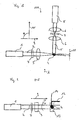
- the Fig. 1 shows an embodiment of a microscope 100 according to the invention.
- the structure comprises a light source 1, the collimated light beam 2 of which is focused into the sample 4 by a cylindrical lens 3. This creates a thin vertical light strip 11 through which fluorescence emission can be induced in the sample 4.
- the emitted light 5 is imaged by detection optics 6 on the flat detector 8, for example a CCD camera.
- the structure is particularly simple.
- the use of dichroic mirrors for separating illumination and fluorescent light in the detection beam path 5 can be dispensed with.
- the filters 7 in the illumination beam 2 and in the detection beam path 5 are glass filters or acousto / electro / magneto-optical filters and allow the selective selection of wavelengths for the illumination and the detection.
- the sample 4 is held in a sample chamber 13 by a holder 12 and is moved in the detection direction 10 through the spatially fixed light plane 11 for the image recording.
- the holder 12 also allows the sample 4 to be rotated about its vertical axis 14, so that the sample 4 can be illuminated and observed from several sides.
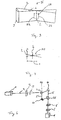
- the Figures 3 and 4 show in principle the above-mentioned illumination beam path 2 generated using the cylindrical lens 3.
- the light emitted by the light source 1 is below a through the cylindrical lens 3, the focal length of which can preferably be in the range between 10 mm and 100 mm relatively small angle ⁇ focused.
- an in the Fig. 3 Object illumination area 20 drawn in dashed lines, which approximately has a flat or plane-like structure or extent and is formed by cylinder sections on both sides of the focus line.
- a thickness dimension c results at the end areas 22, 24 of the object illumination area 20 located in the illumination direction of approximately 60 ⁇ m, which of course depends on the numerical aperture specified for the cylindrical lens 3.
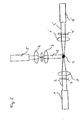
- a modified embodiment of the microscope 100 is shown in which two illumination beam paths 2, 2 'are present.
- each of these two illumination beam paths 2, 2 ' which have oppositely directed illumination directions but corresponding illumination axes, each have a cylinder lens 3, 3' with an optionally assigned filter 7, 7 'and a light source 1, 1'.
- a thin vertical streak of light which, compared to the streak of light in FIG Fig. 1 illustrated embodiment is more homogeneous.
- the emitted light 5 is imaged onto the flat detector 8 by detection optics 6.
- This embodiment of the invention The microscope is particularly suitable for absorbing samples where one-sided illumination cannot illuminate the entire sample.
- a further modification of the microscope 100 according to the invention is indicated.
- the arrow P indicates that the cylinder lens 3 shown there can be rotated about the illumination axis of the illumination beam path 2, for example by 90 °.
- the object illumination region 20 of this illumination beam path 2 thus also rotates, so that, starting from the in FIG Fig. 2 Orientation shown, in which it lies essentially in the plane of the drawing, rotated by 90 ° and then stands perpendicular to the plane of the drawing.
- a further detection beam path 5 'can therefore be provided, in which, with respect to the in FIG Fig. 1 recognizable detection beam path 5, the object 4 to be examined can be viewed at an angle of 90 ° without this object 4 itself having been rotated.
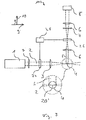
- FIG Fig. 7 An alternatively configured microscope 100 according to the invention is shown in FIG Fig. 7 shown.
- the basic structure and the approach are as in Fig. 1 so that general reference can be made to the preceding statements.
- the lens 3 used here is no longer a cylindrical lens, but a lens that is rotationally symmetrical with respect to the illumination axis 9 of the illumination beam path.
- an object illumination area 20 ' is generated, which is also essentially rotationally symmetrical and can therefore be interpreted as a linear object illumination area or line-like object illumination area, in particular in the area in which the object 4 to be examined or the sample is also positioned .
- this essentially rotationally symmetrical, line-like object illumination area can, of course, depending on the focal length of the lens 3 or the optical system used in the center, be in the range of 10-20 ⁇ m, while the edge areas have dimensions in the range of 40-60 ⁇ m .
- a sample 4 when a sample 4 is positioned in the object illumination area 20 ', no disk-like or area-like area of the sample 4 is illuminated, but a correspondingly line-like area.
- the image of this line-like illuminated area generated in the detection beam path 5 is imaged onto the detector 8 via the optical system of the same, so that an optionally enlarged line image is generated there.
- the detector 8 is constructed as a pixel detector and has a more "one-dimensional" pixel arrangement in adaptation to the line-like image now generated. In this arrangement, the positioning of the pixels is such that a significantly larger number of pixels follow one another in the longitudinal direction of the line-like image generated than transversely thereto.
- the number of pixels in the longitudinal direction or the transverse direction is preferably selected such that the line-like image generated in the detection beam path 5 can be completely recorded by the detector 8 without having to move it. In extreme cases, however, it is also possible to provide a single row of pixels. It must be taken into account here that with decreasing width of such a pixel field and more and more occurring transition to a single pixel line, the number of pixels present in such a line-like arrangement can be increased and in this respect the resolution of the detector 8 can be increased accordingly in this direction.
- a relative movement of this sample 4 with respect to the line-like object illumination area 20 ' is generated.
- the sample 4 can be shifted orthogonally to the line-like object illumination area and also orthogonally to the detection beam path 5, that is to say in the representation of FIG Fig. 7 perpendicular to the plane of the drawing.
- areas of the sample 4 are illuminated in a grid-like manner and gradually line-like, so that an overall image of the sample 4 can be generated in one plane by combining the correspondingly recorded images.
- the sample can also be shifted in the direction of the detection beam path 5 or the detection direction 10, so that different planes of the sample 4 are moved through the focal plane of the illumination beam path 5.
- the sample 4 can be held stationary, while devices 24 and 26 are provided both in the illumination beam path 2 and in the detection beam path 5, which shift these two beam paths 2, 5 in their area close to the sample.
- These devices 24, 26 can be, for example, beam deflection units that each include, for example, a tiltable mirror.
- the two beam deflection units 24, 26 are controlled by a control device 28 in order to coordinate their movement with one another, so that it is ensured that that area of the sample 4 that is currently illuminated by the object illumination area 20 'always passes through the detection beam path 5 to the detector 8 is shown. In this way, scanning of the is otherwise not perpendicular to the plane of the drawing Fig. 7 sample to be moved in one plane is possible.
- the sample 4 can then be shifted again in the detection direction 10 in order to scan several planes one after the other.
- this raster movement of the line-like object illumination area with respect to the sample to be examined generates an illumination plane or a flat object illumination area over time, which has a more homogeneous intensity in the direction of the relative movement than is the case with a corresponding beam expansion in the systems described above, since the intensity profile in the object illumination area is also dependent there on the intensity profile of the focused light beam.
- higher intensities can be achieved through the stronger focusing of the light.
- the laser power is used more efficiently, which is particularly advantageous in the case of weak fluorescence or multiphoton excitation.
- the invention relates to a microscope and a method for the light microscopic examination in which a layer of the sample is illuminated by a thin light strip 11 and the observation is perpendicular to the plane of the light strip he follows.
- the thickness of the light strip 11 thus essentially determines the depth of field of the system.
- the object 4 is moved through the light strip 11, which is stationary with respect to the detector, and fluorescence and / or scattered light is recorded with a flat detector. Highly absorbing or strongly scattering objects 4 are observed from several spatial directions.
- the three-dimensional recordings, which are made from every direction, can subsequently be combined into one recording in which the data are weighted according to their resolution. The resolution of the combined image is then dominated by the lateral resolution of the individual images.
Landscapes
- Physics & Mathematics (AREA)
- General Physics & Mathematics (AREA)
- Chemical & Material Sciences (AREA)
- Analytical Chemistry (AREA)
- Optics & Photonics (AREA)
- Health & Medical Sciences (AREA)
- Biochemistry (AREA)
- General Health & Medical Sciences (AREA)
- Immunology (AREA)
- Life Sciences & Earth Sciences (AREA)
- Pathology (AREA)
- Engineering & Computer Science (AREA)
- Multimedia (AREA)
- Nuclear Medicine, Radiotherapy & Molecular Imaging (AREA)
- Computer Vision & Pattern Recognition (AREA)
- Microscoopes, Condenser (AREA)
- Investigating, Analyzing Materials By Fluorescence Or Luminescence (AREA)
- Investigating Or Analysing Materials By Optical Means (AREA)
- Investigating Materials By The Use Of Optical Means Adapted For Particular Applications (AREA)
Claims (12)
- Microscope avec au moins un trajet de faisceau d'éclairage (2) et au moins un trajet de faisceau de détection (5), comprenant- un dispositif de détection (10) d'au moins un trajet de faisceau de détection (5),- dans lequel le trajet de faisceau d'éclairage (2) et le trajet de faisceau de détection (5) sont approximativement orthogonaux l'un par rapport à l'autre dans une zone d'éclairage d'objet,
caractérisé en ce que
un dispositif de focalisation (3) est prévu pour le au moins un trajet de faisceau d'éclairage (2) pour générer la zone d'éclairage d'objet (20') linéaire s'étendant dans une direction d'un axe d'éclairage du trajet de faisceau d'éclairage (2), configuré pour éclairer des portions linéaires d'un échantillon à étudier ;- un dispositif pour le balayage entre un objet à étudier et le trajet de faisceau d'éclairage (2), le dispositif étant configuré pour échantillonner linéairement l'objet à étudier (4), de sorte qu'au fil du temps une zone d'éclairage d'objet (20) semblable à une surface est générée. - Microscope selon la revendication 1, dans lequel un dispositif de déplacement avec un support (12) est prévu pour générer un mouvement relatif entre la zone d'éclairage d'objet (20) et l'objet à étudier (4) sur le support (12).
- Microscope selon la revendication 2, dans lequel le dispositif de déplacement (12) comprend au moins un axe de rotation (14) disposé dans la direction de la gravité, l'axe de rotation (14) étant disposé sensiblement orthogonalement à l'axe d'éclairage et sensiblement orthogonalement à la direction de détection (10).
- Microscope selon l'une des revendications précédentes,
dans lequel le microscope comporte en outre une chambre à échantillon (13) et l'objet à étudier (4) est disposé sur le support (12) à l'intérieur de la chambre à échantillon (13),
dans lequel le support (12) comprend l'axe de rotation (14) disposé dans la direction de la gravité, de sorte que l'objet à étudier (4) peut tourner dans la chambre à échantillon autour de l'axe de rotation (14) disposé dans la direction de la gravité. - Microscope selon l'une des revendications précédentes, dans lequel un mouvement de rotation de l'objet (4) ou/et un mouvement de translation de l'objet (4) peut être produit par le dispositif de déplacement (12).
- Microscope selon l'une des revendications précédentes, dans lequel le dispositif de focalisation (3 ; 3, 3') comprend au moins une lentille conique, un élément holographique, une plaque de phase, un autre élément optique pour générer un faisceau de Bessel et/ou une lentille à symétrie de révolution pour focaliser la lumière d'éclairage.
- Microscope selon l'une des revendications précédentes, caractérisé en ce que la lumière diffusée ou la lumière fluorescente d'une ou plusieurs longueurs d'onde est utilisée.
- Microscope selon la revendication 7, caractérisé en ce que le microscope comprend deux trajets de faisceau d'éclairage (2,2') et la lumière d'éclairage des deux trajets de faisceau d'éclairage (2,2') interfère dans une direction de l'axe d'éclairage au moins par zones dans la région de la zone d'éclairage d'objet (20).
- Microscope selon l'une des revendications précédentes, comprenant en outre un détecteur de type surface dans la trajectoire du faisceau de détection (5).
- Microscope selon la revendication 9, dans lequel le détecteur de type surface est un détecteur de pixels.
- Procédé pour étudier un objet à étudier avec un microscope optique, caractérisé en ce que le procédé comprend
générer une zone d'éclairage d'objet linéaire et l'éclairage de portions linéaires de l'objet à étudier ;
représenter la zone d'éclairage d'objet linéaire dans un trajet de faisceau de détection, dans lequel le trajet de faisceau d'éclairage (2) et le trajet de faisceau de détection (5) sont disposés dans la zone d'éclairage d'objet de manière approximativement orthogonale l'un par rapport à l'autre, et
échantillonner de manière linéaire l'objet à étudier au moyen d'un balayage entre l'objet à étudier (4) et le trajet de faisceau d'éclairage (2), de sorte qu'au fil du temps, une zone d'éclairage d'objet semblable à une surface (20) est générée. - Procédé selon la revendication 11, comprenant en outre l'assemblage des images linéaires générées par l'échantillonnage linéaire en une image totale.
Applications Claiming Priority (3)
| Application Number | Priority Date | Filing Date | Title |
|---|---|---|---|
| DE10257423A DE10257423A1 (de) | 2002-12-09 | 2002-12-09 | Mikroskop |
| EP03732549A EP1576404B1 (fr) | 2002-12-09 | 2003-06-06 | Microscope ou le sens de l'observation est perpendiculaire au sens de l'eclairage |
| PCT/EP2003/005991 WO2004053558A1 (fr) | 2002-12-09 | 2003-06-06 | Microscope ou le sens de l'observation est perpendiculaire au sens de l'eclairage |
Related Parent Applications (2)
| Application Number | Title | Priority Date | Filing Date |
|---|---|---|---|
| EP03732549A Division EP1576404B1 (fr) | 2002-12-09 | 2003-06-06 | Microscope ou le sens de l'observation est perpendiculaire au sens de l'eclairage |
| EP03732549.5 Division | 2003-06-06 |
Publications (4)
| Publication Number | Publication Date |
|---|---|
| EP2273300A2 EP2273300A2 (fr) | 2011-01-12 |
| EP2273300A3 EP2273300A3 (fr) | 2011-06-08 |
| EP2273300B1 true EP2273300B1 (fr) | 2020-10-28 |
| EP2273300B8 EP2273300B8 (fr) | 2021-03-31 |
Family
ID=32336147
Family Applications (4)
| Application Number | Title | Priority Date | Filing Date |
|---|---|---|---|
| EP03732549A Expired - Lifetime EP1576404B1 (fr) | 2002-12-09 | 2003-06-06 | Microscope ou le sens de l'observation est perpendiculaire au sens de l'eclairage |
| EP09163734.8A Expired - Lifetime EP2107408B1 (fr) | 2002-12-09 | 2003-06-06 | Microscope avec la direction de vue perpendiculaire par rapport à la direction d'eclairage |
| EP10183679.9A Expired - Lifetime EP2273300B8 (fr) | 2002-12-09 | 2003-06-06 | Microscope avec un sens de l'observation pèrpendiculaire au sens de l'éclairage et une méthode d'inspection microscopique |
| EP08000060.7A Expired - Lifetime EP1912089B1 (fr) | 2002-12-09 | 2003-06-06 | Microscope avec la direction de vue perpendiculaire par rapport à la direction d'eclairage |
Family Applications Before (2)
| Application Number | Title | Priority Date | Filing Date |
|---|---|---|---|
| EP03732549A Expired - Lifetime EP1576404B1 (fr) | 2002-12-09 | 2003-06-06 | Microscope ou le sens de l'observation est perpendiculaire au sens de l'eclairage |
| EP09163734.8A Expired - Lifetime EP2107408B1 (fr) | 2002-12-09 | 2003-06-06 | Microscope avec la direction de vue perpendiculaire par rapport à la direction d'eclairage |
Family Applications After (1)
| Application Number | Title | Priority Date | Filing Date |
|---|---|---|---|
| EP08000060.7A Expired - Lifetime EP1912089B1 (fr) | 2002-12-09 | 2003-06-06 | Microscope avec la direction de vue perpendiculaire par rapport à la direction d'eclairage |
Country Status (8)
| Country | Link |
|---|---|
| US (7) | US7554725B2 (fr) |
| EP (4) | EP1576404B1 (fr) |
| JP (2) | JP5259916B2 (fr) |
| AT (1) | ATE520049T1 (fr) |
| AU (2) | AU2003238484B2 (fr) |
| CA (1) | CA2509330C (fr) |
| DE (1) | DE10257423A1 (fr) |
| WO (1) | WO2004053558A1 (fr) |
Families Citing this family (180)
| Publication number | Priority date | Publication date | Assignee | Title |
|---|---|---|---|---|
| AU2003268487A1 (en) * | 2002-09-05 | 2004-03-29 | Nanosys, Inc. | Nanocomposites |
| DE10257423A1 (de) * | 2002-12-09 | 2004-06-24 | Europäisches Laboratorium für Molekularbiologie (EMBL) | Mikroskop |
| US7532749B2 (en) * | 2003-11-18 | 2009-05-12 | Panasonic Corporation | Light processing apparatus |
| JP2005259221A (ja) * | 2004-03-10 | 2005-09-22 | Pioneer Electronic Corp | ホログラム再生装置、及び再生方法 |
| JP4315256B2 (ja) * | 2004-07-08 | 2009-08-19 | パイオニア株式会社 | ホログラム記録再生装置及び、ホログラム再生装置及び方法、並びにコンピュータプログラム |
| DE102005027077C5 (de) * | 2004-11-04 | 2021-01-28 | Leica Microsystems Cms Gmbh | Lichtscheibenmikroskop |
| US8072866B2 (en) * | 2005-03-03 | 2011-12-06 | Pioneer Corporation | Marker selection method for hologram recording device |
| US7485875B2 (en) * | 2005-07-22 | 2009-02-03 | Carl Zeiss Microimaging Gmbh | Resolution-enhanced luminescence microscopy |
| ATE441103T1 (de) | 2005-07-22 | 2009-09-15 | Zeiss Carl Microimaging Gmbh | Auflísungsgesteigerte lumineszenz-mikroskopie |
| JP2007114542A (ja) * | 2005-10-21 | 2007-05-10 | Olympus Corp | 顕微鏡観察装置および顕微鏡観察方法 |
| WO2007065711A1 (fr) * | 2005-12-09 | 2007-06-14 | Europäisches Laboratorium für Molekularbiologie (EMBL) | Support de spécimen de microscope |
| US8421035B2 (en) * | 2006-08-11 | 2013-04-16 | The Regents Of The University Of California | High-resolution microscope using optical amplification |
| DE102007015061A1 (de) * | 2007-03-29 | 2008-10-02 | Carl Zeiss Microimaging Gmbh | Probenhalterung für ein Mikroskop |
| DE102007015063B4 (de) | 2007-03-29 | 2019-10-17 | Carl Zeiss Microscopy Gmbh | Optische Anordnung zum Erzeugen eines Lichtblattes |
| USRE45575E1 (en) | 2007-03-29 | 2015-06-23 | Carl Zeiss Microscopy Gmbh | Optical arrangement for the production of a light-sheet |
| DE102007017598A1 (de) | 2007-04-13 | 2008-10-16 | Carl Zeiss Microimaging Gmbh | Verfahren und Anordnung zum Positionieren eines Lichtblattes in der Fokusebene einer Detektionsoptik |
| DE102007018862A1 (de) | 2007-04-18 | 2008-10-23 | Carl Zeiss Microimaging Gmbh | Objektivwechseleinrichtung für Mikroskope |
| DE102007020577B4 (de) | 2007-04-26 | 2021-09-09 | Carl Zeiss Microscopy Gmbh | Probenhalterung für ein Mikroskop und Verwendung eines Mikroskops mit einer solchen Probenhalterung |
| US7729049B2 (en) | 2007-05-26 | 2010-06-01 | Zeta Instruments, Inc. | 3-d optical microscope |
| US8184364B2 (en) * | 2007-05-26 | 2012-05-22 | Zeta Instruments, Inc. | Illuminator for a 3-D optical microscope |
| DE102007045897A1 (de) * | 2007-09-26 | 2009-04-09 | Carl Zeiss Microimaging Gmbh | Verfahren zur mikroskopischen dreidimensionalen Abbildung einer Probe |
| DE102007047461A1 (de) * | 2007-09-28 | 2009-04-02 | Carl Zeiss Microimaging Gmbh | Verfahren und optische Anordnung zur Untersuchung einer Probe |
| DE102007047464B4 (de) | 2007-09-28 | 2023-03-02 | Carl Zeiss Microscopy Gmbh | Optische Anordnung zur Photomanipulation |
| DE102007048409A1 (de) | 2007-10-09 | 2009-04-16 | Carl Zeiss Microimaging Gmbh | Verfahren zum Positionieren von biologischen Proben in einer mikroskopischen Anordnung |
| DE102007063274B8 (de) * | 2007-12-20 | 2022-12-15 | Albert-Ludwigs-Universität Freiburg | Mikroskop |
| DE102008009216A1 (de) * | 2008-02-13 | 2009-08-20 | Carl Zeiss Microimaging Gmbh | Vorrichtung und Verfahren zum räumlich hochauflösenden Abbilden einer Struktur einer Probe |
| DE102008018476B4 (de) | 2008-04-11 | 2022-12-15 | Carl Zeiss Microscopy Gmbh | Mikroskopievorrichtung |
| DE102008027784B4 (de) | 2008-06-11 | 2021-05-20 | Carl Zeiss Microscopy Gmbh | Verfahren zum Positionieren einer Probe im Detektionsbereich eines Objektivs |
| DE102008028707A1 (de) | 2008-06-17 | 2009-12-24 | Carl Zeiss Microimaging Gmbh | Laser-Scanning-Mikroskop mit einer Laserdiode |
| WO2010014244A2 (fr) * | 2008-07-30 | 2010-02-04 | The Regents Of The University Of California, San Francisco | Microscopie par éclairage de plan sélectif multi-directionnel |
| GB0814039D0 (en) | 2008-07-31 | 2008-09-10 | Imp Innovations Ltd | Optical arrangement for oblique plane microscopy |
| DE102008035933A1 (de) | 2008-07-31 | 2010-02-04 | Carl Zeiss Microlmaging Gmbh | Vorrichtung zum Halten und Positionieren einer Probe relativ zu einem Mikroskopobjektiv |
| US9116353B2 (en) | 2008-09-16 | 2015-08-25 | Yokogawa Electric Corporation | Microscope device |
| JP5311195B2 (ja) * | 2008-09-16 | 2013-10-09 | 横河電機株式会社 | 顕微鏡装置 |
| JP5190886B2 (ja) * | 2008-12-11 | 2013-04-24 | 株式会社ブイ・テクノロジー | 蛍光顕微鏡 |
| SG164292A1 (en) * | 2009-01-13 | 2010-09-29 | Semiconductor Technologies & Instruments Pte | System and method for inspecting a wafer |
| DE102009022912B4 (de) * | 2009-05-27 | 2016-11-17 | Carl Zeiss Ag | Korrelative optische und Teilchenstrahl-Mikroskopie |
| DE102009044984A1 (de) | 2009-09-24 | 2011-03-31 | Carl Zeiss Microimaging Gmbh | Mikroskop |
| DE102009044983A1 (de) | 2009-09-24 | 2011-03-31 | Carl Zeiss Microimaging Gmbh | Mikroskop |
| DE102009044986A1 (de) | 2009-09-24 | 2011-03-31 | Carl Zeiss Microimaging Gmbh | Mikroskop |
| DE102009044987A1 (de) | 2009-09-24 | 2011-03-31 | Carl Zeiss Microimaging Gmbh | Mikroskop |
| WO2011046896A1 (fr) * | 2009-10-13 | 2011-04-21 | Intelligent Imaging Innovations, Inc. | Source laser supercontinuum pour microscopie confocale plein champ, spim et tirf |
| US8767216B2 (en) * | 2009-10-13 | 2014-07-01 | California Institute Of Technology | Holographically illuminated imaging devices |
| JP5852305B2 (ja) | 2009-10-28 | 2016-02-03 | カール ツァイス マイクロスコピー ゲーエムベーハーCarl Zeiss Microscopy Gmbh | 分解能の向上した顕微鏡法および顕微鏡 |
| US8570649B2 (en) * | 2009-10-29 | 2013-10-29 | California Institute Of Technology | Dual-mode raster point scanning/light sheet illumination microscope |
| US8970671B2 (en) * | 2010-02-23 | 2015-03-03 | California Institute Of Technology | Nondiffracting beam detection devices for three-dimensional imaging |
| KR20130004326A (ko) * | 2010-03-05 | 2013-01-09 | 더 제너럴 하스피탈 코포레이션 | 특정 해상도에서 적어도 하나의 해부학적 구조의 미세 영상을 제공하는 시스템, 방법 및 컴퓨터 접근 가능 매체 |
| DE102010013223B4 (de) * | 2010-03-29 | 2016-05-12 | Lavision Biotec Gmbh | Verfahren und Anordnung zur Mikroskopie |
| US9389408B2 (en) | 2010-07-23 | 2016-07-12 | Zeta Instruments, Inc. | 3D microscope and methods of measuring patterned substrates |
| WO2012027542A2 (fr) * | 2010-08-25 | 2012-03-01 | California Institute Of Technology | Microscopie à feuille de lumière orthogonale et tomographie optique informatisée réalisées simultanément |
| DE102010060121C5 (de) * | 2010-10-22 | 2023-09-28 | Leica Microsystems Cms Gmbh | SPIM-Mikroskop mit sequenziellem Lightsheet |
| DE102010044013A1 (de) * | 2010-11-16 | 2012-05-16 | Carl Zeiss Microimaging Gmbh | Tiefenauflösungsgesteigerte Mikroskopie |
| DE102010063412B4 (de) | 2010-12-17 | 2013-06-06 | Laser Zentrum Hannover E.V. | Technik zur tomographischen Bilderfassung |
| US10908403B2 (en) * | 2011-02-14 | 2021-02-02 | European Molecular Biology Laboratory (Embl) | Light-pad microscope for high-resolution 3D fluorescence imaging and 2D fluctuation spectroscopy |
| DE102011000835C5 (de) * | 2011-02-21 | 2019-08-22 | Leica Microsystems Cms Gmbh | Abtastmikroskop und Verfahren zur lichtmikroskopischen Abbildung eines Objektes |
| US9086536B2 (en) | 2011-03-09 | 2015-07-21 | California Institute Of Technology | Talbot imaging devices and systems |
| US8946619B2 (en) | 2011-04-20 | 2015-02-03 | California Institute Of Technology | Talbot-illuminated imaging devices, systems, and methods for focal plane tuning |
| EP2766765B1 (fr) | 2011-10-11 | 2018-08-15 | Carl Zeiss Microscopy GmbH | Microscope et procédé de microscopie spim |
| DE102012015861A1 (de) | 2011-10-11 | 2013-04-11 | Carl Zeiss Microscopy Gmbh | Mikroskop und Verfahren zur SPIM-Mikroskopie |
| DE102012019466A1 (de) | 2012-09-28 | 2014-04-03 | Carl Zeiss Microscopy Gmbh | Mikroskop und Verfahren zur SPIM Mikroskopie |
| DE102011054914A1 (de) | 2011-10-28 | 2013-05-02 | Leica Microsystems Cms Gmbh | Verfahren und Anordnung zur Beleuchtung einer Probe |
| DE202011110077U1 (de) | 2011-10-28 | 2012-11-29 | Leica Microsystems Cms Gmbh | Anordnung zur Beleuchtung einer Probe |
| EP2859326B1 (fr) | 2012-06-11 | 2020-04-29 | Helmholtz Zentrum München Deutsches Forschungszentrum für Gesundheit und Umwelt GmbH | Système d'imagerie et procédé d'imagerie d'objet |
| DE102012013163B4 (de) * | 2012-07-02 | 2022-08-25 | Carl Zeiss Microscopy Gmbh | Mikroskop und Verfahren zur Lichtscheibenmikroskopie |
| DE102012211462A1 (de) | 2012-07-03 | 2014-01-23 | Carl Zeiss Microscopy Gmbh | Verfahren zur Vorbereitung und Durchführung der Aufnahme von Bildstapeln einer Probe aus verschiedenen Orientierungswinkeln |
| DE102012016347B4 (de) | 2012-08-16 | 2022-09-08 | Carl Zeiss Microscopy Gmbh | Mikroskop zur SPIM Mikroskopie |
| DE102012214568A1 (de) | 2012-08-16 | 2014-02-20 | Leica Microsystems Cms Gmbh | Optische Anordnung und ein Mikroskop |
| DE202012007891U1 (de) | 2012-08-16 | 2012-11-23 | Carl Zeiss Microscopy Gmbh | Mikroskop und Probenkammer für die SPIM Mikroskopie |
| US9404869B2 (en) | 2012-10-09 | 2016-08-02 | Howard Hughes Medical Institute | Multiview light-sheet microscopy |
| DE102012020241A1 (de) | 2012-10-12 | 2014-04-17 | Carl Zeiss Microscopy Gmbh | Bildaufnahmevorrichtung und Verfahren zur Aufnahme einer Bildersequenz |
| DE102012020240A1 (de) | 2012-10-12 | 2014-04-17 | Carl Zeiss Microscopy Gmbh | Mikroskop und Verfahren zur SPIM Mikroskopie |
| DE102012020242A1 (de) | 2012-10-12 | 2014-04-17 | Carl Zeiss Microscopy Gmbh | Bildaufnahmevorrichtung und Verfahren zur Aufnahme einer Bildersequenz |
| DE102012218920A1 (de) | 2012-10-17 | 2014-04-17 | Carl Zeiss Microscopy Gmbh | Vorrichtung zur Beleuchtung einer Probe |
| DE102012110077A1 (de) | 2012-10-23 | 2014-06-26 | Karlsruher Institut für Technologie | Mikroskop mit mindestens einem Beleuchtungsstrahl in Form einer Lichtscheibe |
| DE102012024995A1 (de) | 2012-12-20 | 2014-06-26 | Carl Zeiss Microscopy Gmbh | Mikroskop und Verfahren zur SPIM Mikroskopie |
| DE102013002981B4 (de) | 2013-02-20 | 2022-04-28 | Hans-Ulrich Dodt | 3D-Mikroskop |
| DE102013213781A1 (de) | 2013-03-20 | 2014-09-25 | Leica Microsystems Cms Gmbh | Verfahren und optische Anordnung zum Manipulieren und Abbilden einer mikroskopischen Probe |
| JP6086366B2 (ja) | 2013-04-05 | 2017-03-01 | 国立研究開発法人理化学研究所 | 顕微鏡、焦準器具、流体保持器具、及び光学ユニット |
| US9257260B2 (en) | 2013-04-27 | 2016-02-09 | Kla-Tencor Corporation | Method and system for adaptively scanning a sample during electron beam inspection |
| WO2014178514A1 (fr) * | 2013-04-29 | 2014-11-06 | 한국식품연구원 | Module de balayage, dispositif de détection mettant en œuvre un faisceau de bessel, sonde de détection, et dispositif de détection de type de sonde |
| DE202013012727U1 (de) | 2013-05-10 | 2018-11-28 | European Molecular Biology Laboratory | Mikroskopmodul zum Abbilden einer Probe |
| EP2801855B1 (fr) | 2013-05-10 | 2019-07-17 | European Molecular Biology Laboratory | Module de microscope pour l'imagerie d'un échantillon |
| DE102013208872B4 (de) | 2013-05-14 | 2023-08-17 | Carl Zeiss Microscopy Gmbh | Verfahren zur Erzeugung eines Bildes einer Probe |
| DE102013105586B4 (de) | 2013-05-30 | 2023-10-12 | Carl Zeiss Ag | Vorrichtung zur Abbildung einer Probe |
| DE102013211426A1 (de) | 2013-06-18 | 2014-12-18 | Leica Microsystems Cms Gmbh | Verfahren und optische Vorrichtung zum mikroskopischen Untersuchen einer Vielzahl von Proben |
| DE102013106895B4 (de) | 2013-07-01 | 2015-09-17 | Leica Microsystems Cms Gmbh | Lichtmikroskopisches Verfahren zur Lokalisierung von Punktobjekten |
| DE102013107297B4 (de) | 2013-07-10 | 2025-04-24 | Carl Zeiss Microscopy Gmbh | Anordnung zur Lichtblattmikroskopie |
| DE102013107298B4 (de) | 2013-07-10 | 2025-07-17 | Carl Zeiss Microscopy Gmbh | Anordnung zur Lichtblattmikroskopie |
| US9581798B2 (en) | 2013-07-22 | 2017-02-28 | Fundacio Institut De Ciencies Fotoniques | Light sheet-based imaging device with extended depth of field |
| DE102013110093B3 (de) * | 2013-09-13 | 2015-01-22 | Johann Wolfgang Goethe-Universität | Küvette für eine inverse Fluoreszenz-Untersuchung |
| US10539772B2 (en) * | 2013-10-09 | 2020-01-21 | Howard Hughes Medical Institute | Multiview light-sheet microscopy |
| DE102013112600A1 (de) | 2013-11-15 | 2015-05-21 | Carl Zeiss Microscopy Gmbh | Optisches Übertragungssystem und Mikroskop mit einem solchen Übertragungssystem |
| DE102013112595B4 (de) | 2013-11-15 | 2024-08-01 | Carl Zeiss Microscopy Gmbh | Anordnung zur Lichtblattmikroskopie |
| DE102013112596B4 (de) | 2013-11-15 | 2023-12-28 | Carl Zeiss Microscopy Gmbh | Anordnung zur Lichtblattmikroskopie |
| DE102013021222B4 (de) * | 2013-12-17 | 2023-05-04 | Carl Zeiss Microscopy Gmbh | Mikroskop und Mikroskopieverfahren |
| DE102013226277A1 (de) * | 2013-12-17 | 2015-06-18 | Leica Microsystems Cms Gmbh | Verfahren und Vorrichtung zum Untersuchen einer Probe mittels optischer Projektionstomografie |
| DE102013021542A1 (de) | 2013-12-18 | 2015-06-18 | Carl Zeiss Microscopy Gmbh | Mikroskop und Verfahren zur SPIM Mikroskopie |
| JP2015135463A (ja) | 2013-12-19 | 2015-07-27 | オリンパス株式会社 | 顕微鏡装置、及び、顕微鏡システム |
| WO2015108846A1 (fr) | 2014-01-14 | 2015-07-23 | Applied Scientific Instrumentation, Inc. | Générateur de feuilles de lumière |
| DE102014104977B4 (de) | 2014-04-08 | 2023-11-30 | Carl Zeiss Microscopy Gmbh | Anordnung zur Lichtblattmikroskopie sowie Mikroskopobjektiv für die Lichtblattmikroskopie |
| CN107003505B (zh) * | 2014-08-13 | 2021-03-05 | 丹尼尔·萨默·加鲁 | 线扫描、样品扫描、多模式共聚焦显微镜 |
| DE102014113827A1 (de) | 2014-09-24 | 2016-03-24 | Carl Zeiss Microscopy Gmbh | Vorrichtung zur Abbildung einer Probe |
| DE102015114756B4 (de) | 2014-09-25 | 2021-07-22 | Leica Microsystems Cms Gmbh | Spiegelvorrichtung |
| ES2567379B1 (es) | 2014-10-21 | 2017-02-03 | Universidad Carlos Iii De Madrid | Microscopio y procedimiento para la generación de imágenes 3D de una colección demuestras |
| US10181190B2 (en) | 2014-11-04 | 2019-01-15 | Olympus Corporation | Microscope and microscope image acquisition method |
| JP2016090766A (ja) * | 2014-11-04 | 2016-05-23 | オリンパス株式会社 | 顕微鏡 |
| US10007100B2 (en) | 2014-11-04 | 2018-06-26 | Olympus Corporation | Light sheet illumination microscope and light sheet illumination method |
| DE102014116174A1 (de) | 2014-11-06 | 2016-05-12 | Carl Zeiss Microscopy Gmbh | Verfahren zur Erzeugung eines Bildes einer Probe |
| DE102014119255A1 (de) | 2014-12-19 | 2016-06-23 | Carl Zeiss Microscopy Gmbh | Verfahren zur lichtblattmikroskopischen Untersuchung einer Probe |
| FR3031196B1 (fr) | 2014-12-29 | 2017-01-13 | Karla Balaa | Dispositif pour realiser de la microscopie a feuille de lumiere |
| JP6635052B2 (ja) * | 2015-02-05 | 2020-01-22 | 株式会社ニコン | 構造化照明顕微鏡、及び観察方法 |
| US10222600B2 (en) | 2015-02-23 | 2019-03-05 | The Research Foundation For The State University Of New York | Method and apparatus for tiling light sheet selective plane illumination microscopy with real-time optimized light sheet |
| CN104677871A (zh) * | 2015-02-27 | 2015-06-03 | 中国科学院自动化研究所 | 多光子激发光片照明显微成像系统 |
| DE102015103802A1 (de) | 2015-03-16 | 2016-09-22 | Carl Zeiss Microscopy Gmbh | Verfahren und Anordnung zur lichtblattmikroskopischen Untersuchung einer Probe |
| EP4220270A1 (fr) | 2015-04-13 | 2023-08-02 | Leica Microsystems CMS GmbH | Procédé et dispositif d'analyse d'un échantillon |
| JP6417262B2 (ja) | 2015-04-15 | 2018-11-07 | オリンパス株式会社 | シート照明顕微鏡 |
| LU92695B1 (de) | 2015-04-17 | 2016-10-18 | Leica Microsystems | Verfahren und vorrichtung zur spim-untersuchung einer probe |
| WO2016178856A1 (fr) * | 2015-05-01 | 2016-11-10 | The Board Of Regents Of The University Of Texas System | Feuilles de lumière uniformes et évolutives générées par focalisation étendue |
| JP6503221B2 (ja) * | 2015-05-13 | 2019-04-17 | オリンパス株式会社 | 3次元情報取得装置、及び、3次元情報取得方法 |
| DE102015209756A1 (de) | 2015-05-28 | 2016-12-01 | Carl Zeiss Microscopy Gmbh | Anordnung und Verfahren zur Lichtblattmikroskopie |
| DE102015209758A1 (de) | 2015-05-28 | 2016-12-01 | Carl Zeiss Microscopy Gmbh | Anordnung und Verfahren zur Strahlformung und zur Lichtblattmikroskopie |
| JP6552881B2 (ja) * | 2015-06-12 | 2019-07-31 | オリンパス株式会社 | 顕微鏡および顕微鏡画像取得方法 |
| EP3341781B1 (fr) | 2015-08-24 | 2020-04-22 | Leica Microsystems CMS GmbH | Ensemble d'éclairage pour un microscope à feuille de lumière |
| JP6491578B2 (ja) * | 2015-09-07 | 2019-03-27 | オリンパス株式会社 | シート照明顕微鏡システム、画像処理装置、シート照明顕微鏡法、及び、プログラム |
| JP6796917B2 (ja) | 2015-09-18 | 2020-12-09 | シスメックス株式会社 | 粒子撮像装置および粒子撮像方法 |
| ITUB20153920A1 (it) | 2015-09-28 | 2017-03-28 | Milano Politecnico | Dispositivo optofluidico. |
| US11092792B2 (en) | 2015-10-09 | 2021-08-17 | Leica Microsystems Cms Gmbh | Method and apparatus for examining a sample using structured light-sheet illumination |
| LU92846B1 (de) | 2015-10-09 | 2017-05-02 | Leica Microsystems | Verfahren und Beleuchtungsanordnung zum Beleuchten einer Probenschicht mit einem Lichtblatt |
| WO2017075275A1 (fr) | 2015-10-29 | 2017-05-04 | The Board Of Trustees Of The Leland Stanford Junior University | Procédés et systèmes d'imagerie d'un échantillon biologique |
| JP6570427B2 (ja) * | 2015-11-06 | 2019-09-04 | 浜松ホトニクス株式会社 | 画像取得装置、画像取得方法、及び空間光変調ユニット |
| LU92925B1 (de) | 2015-12-23 | 2017-09-25 | Leica Microsystems | Verfahren zum Untersuchen einer Probe mittels Lichtblatt-Mikroskopie und Lichtblatt-Mikroskop |
| US10509215B2 (en) * | 2016-03-14 | 2019-12-17 | Olympus Corporation | Light-field microscope |
| LU93022B1 (de) | 2016-04-08 | 2017-11-08 | Leica Microsystems | Verfahren und Mikroskop zum Untersuchen einer Probe |
| US10876970B2 (en) | 2016-04-12 | 2020-12-29 | The Board Of Regents Of The University Of Texas System | Light-sheet microscope with parallelized 3D image acquisition |
| DE102016108384B3 (de) | 2016-05-04 | 2017-11-09 | Leica Microsystems Cms Gmbh | Vorrichtung und Verfahren zur lichtblattartigen Beleuchtung einer Probe |
| JP2017203822A (ja) * | 2016-05-09 | 2017-11-16 | オリンパス株式会社 | 照明設定方法、シート照明顕微鏡装置、及びプログラム |
| LU93117B1 (de) | 2016-06-23 | 2018-01-24 | Leica Microsystems | Beleuchtungsvorrichtung für ein Mikroskop |
| JP2017227788A (ja) * | 2016-06-23 | 2017-12-28 | オリンパス株式会社 | 顕微鏡および顕微鏡画像取得方法 |
| EP3475753B1 (fr) | 2016-06-24 | 2025-04-09 | Howard Hughes Medical Institute | Réglage automatique de géométrie de nappe de lumière dans un microscope |
| LU93143B1 (de) | 2016-07-06 | 2018-03-05 | Leica Microsystems | Verfahren zum Untersuchen einer Probe sowie Vorrichtung zum Ausführen eines solchen Verfahrens |
| DE102017119169B4 (de) | 2016-08-22 | 2023-07-27 | Leica Microsystems Cms Gmbh | Verfahren und Vorrichtung zur SPIM-Untersuchung einer Probe |
| EP4273594A3 (fr) * | 2016-09-09 | 2024-01-10 | The University of North Carolina at Chapel Hill | Systèmes d'éclairage incliné destinés à des microscopes à fluorescence |
| DE102016117675B4 (de) * | 2016-09-20 | 2018-07-05 | Leica Microsystems Cms Gmbh | Mikroskop mit einem Beleuchtungsmodul |
| US10310246B2 (en) * | 2016-09-28 | 2019-06-04 | SCREEN Holdings Co., Ltd. | Converter, illuminator, and light sheet fluorescence microscope |
| JP6423841B2 (ja) | 2016-10-11 | 2018-11-14 | 浜松ホトニクス株式会社 | 試料観察装置及び試料観察方法 |
| DE102016120683A1 (de) | 2016-10-28 | 2018-05-03 | Carl Zeiss Microscopy Gmbh | Lichtblattmikroskop |
| EP3538941B1 (fr) * | 2016-11-10 | 2025-04-23 | The Trustees of Columbia University in the City of New York | Procédés d'imagerie rapide de grands échantillons à haute résolution |
| JP2018128604A (ja) | 2017-02-09 | 2018-08-16 | オリンパス株式会社 | 顕微鏡装置 |
| JP2018169502A (ja) | 2017-03-30 | 2018-11-01 | オリンパス株式会社 | 顕微鏡装置 |
| US12474561B2 (en) | 2017-04-24 | 2025-11-18 | Igor Lyuboshenko | Automatic correction of spherical aberration in selective plane illumination microscopy |
| US10768400B2 (en) | 2017-04-24 | 2020-09-08 | Igor Lyuboshenko | Varying an illumination path of a selective plane illumination microscopy |
| US10261302B1 (en) | 2017-04-24 | 2019-04-16 | Igor Lyuboshenko | Sample holder for microscopy |
| US11156822B2 (en) | 2017-04-24 | 2021-10-26 | Igor Lyuboshenko | Selective plane illumination microscopy with multiple illumination units scanning an object in sync with a digital camera rolling shutter |
| DE102017108874A1 (de) * | 2017-04-26 | 2018-10-31 | Carl Zeiss Ag | Materialprüfung mit strukturierter Beleuchtung |
| US11287627B2 (en) | 2017-06-30 | 2022-03-29 | Chrysanthe Preza | Multi-focal light-sheet structured illumination fluorescence microscopy system |
| ES2695798B2 (es) | 2017-07-04 | 2019-12-04 | Univ Madrid Carlos Iii | Dispositivo rotativo de cambio de objetivo para microscopio de haz láser plano |
| US11169092B2 (en) | 2017-07-11 | 2021-11-09 | Hamamatsu Photonics K.K. | Sample observation device and sample observation method |
| CN111051954A (zh) * | 2017-07-20 | 2020-04-21 | 维微恩提斯显微镜有限责任公司 | 显微镜、操作显微镜的方法和对样本进行成像的方法 |
| DE102017118691A1 (de) * | 2017-08-16 | 2019-02-21 | Georg-August-Universität Göttingen Stiftung Öffentlichen Rechts, Universitätsmedizin | Verfahren zur Lichtblatt-mikroskopischen Untersuchung von insbesondere biologischen Proben und Lichtblatt-Mikroskop |
| DE102017122718A1 (de) | 2017-09-29 | 2019-04-04 | Carl Zeiss Microscopy Gmbh | Verfahren und Vorrichtung zur optischen Untersuchung einer Vielzahl mikroskopischer Proben |
| PL233602B1 (pl) * | 2017-10-16 | 2019-11-29 | Inst Biologii Doswiadczalnej Im M Nenckiego Polskiej Akademii Nauk | Urzadzenie do obrazowania przezroczystych obiektow |
| EP3495865A1 (fr) | 2017-12-07 | 2019-06-12 | European Molecular Biology Laboratory | Porte-échantillon pour l'imagerie d'une pluralité d'échantillons |
| WO2019148008A1 (fr) | 2018-01-26 | 2019-08-01 | University Of Washington | Appareils et procédés de microscopie à feuille de lumière à balayage numérique à directions multiples |
| DE102018102241B4 (de) * | 2018-02-01 | 2022-02-24 | Leica Microsystems Cms Gmbh | Verfahren zum Abbilden einer Probe mittels eines Lichtblattmikroskops sowie ein Lichtblattmikroskop |
| JP7114272B2 (ja) | 2018-02-28 | 2022-08-08 | 浜松ホトニクス株式会社 | ライトシート顕微鏡及び試料観察方法 |
| US12153227B2 (en) | 2018-03-12 | 2024-11-26 | The University Of North Carolina At Chapel Hill | Light disc microscopy for fluorescence microscopes |
| WO2019178093A1 (fr) | 2018-03-12 | 2019-09-19 | The University Of North Carolina At Chapel Hill | Microscopie à image miroir pour collecte accrue |
| WO2019178090A1 (fr) | 2018-03-12 | 2019-09-19 | The University Of North Carolina At Chapel Hill | Microscopie à disque optique pour microscopes à fluorescence |
| US11209367B2 (en) * | 2018-08-27 | 2021-12-28 | Yale University | Multi-color imaging using salvaged fluorescence |
| ES2749742B2 (es) | 2018-09-21 | 2021-04-06 | Univ Madrid Carlos Iii | Microscopio y procedimiento de haz láser plano para muestras extensas |
| JP7076586B2 (ja) * | 2019-02-06 | 2022-05-27 | オリンパス株式会社 | 撮像装置 |
| DE102020128524A1 (de) | 2020-10-29 | 2022-05-05 | Carl Zeiss Microscopy Gmbh | Lichtblattmikroskop und Verfahren der Lichtblattmikroskopie |
| CN117043655A (zh) | 2021-01-22 | 2023-11-10 | 维微恩提斯显微镜有限责任公司 | 用于对样品进行成像的显微镜 |
| DE102021104871A1 (de) | 2021-03-01 | 2022-09-01 | Carl Zeiss Microscopy Gmbh | Verfahren und Vorrichtung zur lichtblattmikroskopischen Untersuchung einer Probe |
| US12443023B2 (en) | 2021-05-14 | 2025-10-14 | Igor Lyuboshenko | Light sheet microscope having streamlined field of view changes |
| WO2022268325A1 (fr) | 2021-06-24 | 2022-12-29 | Leica Microsystems Cms Gmbh | Objet d'étalonnage pour l'étalonnage d'un système d'imagerie |
| EP4413349A1 (fr) | 2021-10-05 | 2024-08-14 | Leica Microsystems CMS GmbH | Porte-échantillon et procédé d'imagerie d'un échantillon |
| WO2023057349A1 (fr) | 2021-10-05 | 2023-04-13 | Leica Microsystems Cms Gmbh | Système et procédé d'imagerie |
| DE102022125117A1 (de) | 2022-09-29 | 2024-04-04 | Carl Zeiss Microscopy Gmbh | Lichtblattmikroskop |
| CN118311030A (zh) * | 2024-04-11 | 2024-07-09 | 东海实验室 | 一种基于数字全息的海洋浮游生物成像仪及数据处理方法 |
Citations (2)
| Publication number | Priority date | Publication date | Assignee | Title |
|---|---|---|---|---|
| US5570228A (en) * | 1991-04-19 | 1996-10-29 | Edge Scientific Instrument Company Llc | Fiber optic illumination system and method for a high definition light microscope |
| DE4326473C2 (de) * | 1993-08-06 | 1997-05-15 | European Molecular Biology Lab Embl | Konfokales Mikroskop |
Family Cites Families (39)
| Publication number | Priority date | Publication date | Assignee | Title |
|---|---|---|---|---|
| GB1499882A (en) * | 1975-02-14 | 1978-02-01 | Rolls Royce | Sound attenuating structure |
| JPS5324637U (fr) * | 1976-08-09 | 1978-03-02 | ||
| DE3424108A1 (de) * | 1984-06-29 | 1986-01-09 | Bernhard Prof. Dr.-Ing. 4300 Essen Schrader | Probenanordnung zur spektrometrie, verfahren zur messung von lumineszenz und streuung und verwendung der probenanordnung |
| US4700298A (en) * | 1984-09-14 | 1987-10-13 | Branko Palcic | Dynamic microscope image processing scanner |
| IE56166B1 (en) * | 1985-02-15 | 1991-05-08 | Tekscan Ltd | Manipulator means |
| US4621911A (en) * | 1985-03-12 | 1986-11-11 | Carnegie-Mellon University | Standing wave luminescence microscopy |
| NL8600785A (nl) * | 1986-03-27 | 1987-10-16 | Asm Lithography Bv | Positioneerinrichting met een z-manipulator en een o-manipulator. |
| JPH07122694B2 (ja) | 1986-10-16 | 1995-12-25 | オリンパス光学工業株式会社 | 顕微鏡用照明装置 |
| JPS63306413A (ja) * | 1987-06-09 | 1988-12-14 | Olympus Optical Co Ltd | 走査型光学顕微鏡 |
| JPH0210230A (ja) | 1988-06-29 | 1990-01-16 | Fujitsu Ltd | 光強度測定装置 |
| JPH0732184B2 (ja) | 1989-03-13 | 1995-04-10 | 株式会社東芝 | 化合物半導体エピタキシャル膜の評価方法 |
| US5104218A (en) * | 1989-11-09 | 1992-04-14 | General Atomics | Micropipette adaptor for spectrofluorimeters |
| JP3102493B2 (ja) | 1990-09-19 | 2000-10-23 | 株式会社日立製作所 | 異物検査方法及びその装置 |
| JPH05324637A (ja) | 1992-05-15 | 1993-12-07 | Hitachi Ltd | 文書作成装置 |
| JPH07174687A (ja) | 1993-12-20 | 1995-07-14 | Zexel Corp | レーザドップラー法を利用した粒子分析方法 |
| JPH07253309A (ja) | 1994-03-14 | 1995-10-03 | Hitachi Electron Eng Co Ltd | ラインセンサの合焦方法 |
| JP3412322B2 (ja) | 1995-03-30 | 2003-06-03 | 横河電機株式会社 | 共焦点顕微鏡 |
| JPH08327947A (ja) | 1995-06-02 | 1996-12-13 | Imeeji Joho Kagaku Kenkyusho | 回折格子を用いる立体表示装置 |
| US5710625A (en) * | 1996-04-30 | 1998-01-20 | Hughes Electronics | Spectral oil immersion cell |
| DE19720513A1 (de) | 1997-05-16 | 1998-11-19 | Daniel Huber | Anordnung zur Erzeugung von dünnen Lichtebenen für die photographische Erfassung von Objekten |
| US6294327B1 (en) * | 1997-09-08 | 2001-09-25 | Affymetrix, Inc. | Apparatus and method for detecting samples labeled with material having strong light scattering properties, using reflection mode light and diffuse scattering |
| US6249341B1 (en) * | 1999-01-25 | 2001-06-19 | Amnis Corporation | Imaging and analyzing parameters of small moving objects such as cells |
| JP3734010B2 (ja) * | 1999-06-28 | 2006-01-11 | 横河電機株式会社 | 共焦点光スキャナ |
| DE10026830A1 (de) * | 2000-05-30 | 2001-12-06 | Zeiss Carl Jena Gmbh | Optischer Sensor zur Messung des Abstands und/oder der Neigung einer Fläche |
| JP3929717B2 (ja) * | 2001-03-30 | 2007-06-13 | 株式会社ニデック | 角膜顕微鏡装置 |
| KR20020084786A (ko) * | 2001-05-04 | 2002-11-11 | 이재웅 | 선형 선 스캐닝을 이용하는 공초점 영상 형성 장치 및 방법 |
| GB0112392D0 (en) | 2001-05-22 | 2001-07-11 | Medical Res Council | Optical imaging appartus and associated specimen support means |
| JP3938343B2 (ja) | 2002-08-09 | 2007-06-27 | インターナショナル・ビジネス・マシーンズ・コーポレーション | タスク管理システム、プログラム、及び制御方法 |
| DE10257423A1 (de) * | 2002-12-09 | 2004-06-24 | Europäisches Laboratorium für Molekularbiologie (EMBL) | Mikroskop |
| JP4127152B2 (ja) | 2003-08-05 | 2008-07-30 | ソニー株式会社 | データ記録再生装置及び方法 |
| WO2005096061A1 (fr) * | 2004-03-30 | 2005-10-13 | Univ Mcgill | Microscope a profil de lumiere et procede associe |
| DE102004034962A1 (de) * | 2004-07-16 | 2006-02-16 | Carl Zeiss Jena Gmbh | Mikroskop mit erhöhter Auflösung |
| DE102007063274B8 (de) | 2007-12-20 | 2022-12-15 | Albert-Ludwigs-Universität Freiburg | Mikroskop |
| WO2010014244A2 (fr) * | 2008-07-30 | 2010-02-04 | The Regents Of The University Of California, San Francisco | Microscopie par éclairage de plan sélectif multi-directionnel |
| US8711211B2 (en) | 2010-06-14 | 2014-04-29 | Howard Hughes Medical Institute | Bessel beam plane illumination microscope |
| US10051240B2 (en) | 2010-06-14 | 2018-08-14 | Howard Hughes Medical Institute | Structured plane illumination microscopy |
| WO2012027542A2 (fr) * | 2010-08-25 | 2012-03-01 | California Institute Of Technology | Microscopie à feuille de lumière orthogonale et tomographie optique informatisée réalisées simultanément |
| US9404869B2 (en) * | 2012-10-09 | 2016-08-02 | Howard Hughes Medical Institute | Multiview light-sheet microscopy |
| DE102012020240A1 (de) * | 2012-10-12 | 2014-04-17 | Carl Zeiss Microscopy Gmbh | Mikroskop und Verfahren zur SPIM Mikroskopie |
-
2002
- 2002-12-09 DE DE10257423A patent/DE10257423A1/de not_active Ceased
-
2003
- 2003-06-06 EP EP03732549A patent/EP1576404B1/fr not_active Expired - Lifetime
- 2003-06-06 EP EP09163734.8A patent/EP2107408B1/fr not_active Expired - Lifetime
- 2003-06-06 US US10/538,081 patent/US7554725B2/en not_active Expired - Lifetime
- 2003-06-06 JP JP2004557847A patent/JP5259916B2/ja not_active Expired - Lifetime
- 2003-06-06 EP EP10183679.9A patent/EP2273300B8/fr not_active Expired - Lifetime
- 2003-06-06 EP EP08000060.7A patent/EP1912089B1/fr not_active Expired - Lifetime
- 2003-06-06 AT AT03732549T patent/ATE520049T1/de active
- 2003-06-06 AU AU2003238484A patent/AU2003238484B2/en not_active Expired
- 2003-06-06 CA CA2509330A patent/CA2509330C/fr not_active Expired - Lifetime
- 2003-06-06 WO PCT/EP2003/005991 patent/WO2004053558A1/fr not_active Ceased
-
2006
- 2006-11-03 US US11/592,331 patent/US8970950B2/en active Active
-
2009
- 2009-05-19 US US12/468,517 patent/US20090225413A1/en not_active Abandoned
-
2010
- 2010-02-15 AU AU2010200554A patent/AU2010200554B2/en not_active Expired
-
2011
- 2011-07-19 JP JP2011158280A patent/JP5738108B2/ja not_active Expired - Lifetime
-
2013
- 2013-01-22 US US13/746,597 patent/US9857577B2/en not_active Expired - Fee Related
-
2015
- 2015-02-03 US US14/612,541 patent/US9823455B2/en not_active Expired - Fee Related
-
2017
- 2017-11-20 US US15/818,045 patent/US11042015B2/en not_active Expired - Lifetime
-
2021
- 2021-05-21 US US17/327,134 patent/US20210278649A1/en not_active Abandoned
Patent Citations (2)
| Publication number | Priority date | Publication date | Assignee | Title |
|---|---|---|---|---|
| US5570228A (en) * | 1991-04-19 | 1996-10-29 | Edge Scientific Instrument Company Llc | Fiber optic illumination system and method for a high definition light microscope |
| DE4326473C2 (de) * | 1993-08-06 | 1997-05-15 | European Molecular Biology Lab Embl | Konfokales Mikroskop |
Also Published As
Similar Documents
| Publication | Publication Date | Title |
|---|---|---|
| EP2107408B1 (fr) | Microscope avec la direction de vue perpendiculaire par rapport à la direction d'eclairage | |
| DE102010060121B4 (de) | SPIM-Mikroskop mit sequenziellem Lightsheet | |
| EP1186930B1 (fr) | Appareil pour investigation et manipulation d'objects microscopiques | |
| DE60206388T2 (de) | Drehbarer probenhalter zur abbildung einer probe | |
| DE102011051042B4 (de) | Abtastmikroskop und Verfahren zur lichtmikroskopischen Abbildung eines Objektes | |
| DE102007047464B4 (de) | Optische Anordnung zur Photomanipulation | |
| DE19801139A1 (de) | Punktabtastendes Luminiszenz-Mikroskop | |
| EP3283917B1 (fr) | Procédé et dispositif d'analyse d'un échantillon | |
| WO2004051341A1 (fr) | Microscope a balayage ayant un scanner a fente a foyer commun destine a representer un objet | |
| DE102013017468B4 (de) | Verfahren zum Erstellen eines Mikroskopbildes und Mikroskopievorrichtung | |
| DE102012110077A1 (de) | Mikroskop mit mindestens einem Beleuchtungsstrahl in Form einer Lichtscheibe | |
| DE102007017598A1 (de) | Verfahren und Anordnung zum Positionieren eines Lichtblattes in der Fokusebene einer Detektionsoptik | |
| DE102015209756A1 (de) | Anordnung und Verfahren zur Lichtblattmikroskopie | |
| DE102010013223A1 (de) | Verfahren und Anordnung zur Mikroskopie | |
| EP4453627A1 (fr) | Microscope et procédé pour microscopie | |
| WO2020126419A1 (fr) | Procédé permettant de faire fonctionner une chambre à échantillon pour une formation d'images microscopiques, dispositif et chambre à échantillon | |
| WO2014191383A1 (fr) | Procédé de microdissection au laser et système de microdissection au laser | |
| DE102022203632A1 (de) | Bilderfassungsverfahren in der Lichtfeldmikroskopie und Lichtfeldmikroskop | |
| WO2016166374A1 (fr) | Procédé et dispositif d'analyse spim d'un échantillon | |
| EP2784564A1 (fr) | Microscope lumineux et procédé d'analyse d'un échantillon microscopique | |
| DE19950225A1 (de) | Anordnung zur optischen Abtastung eines Objekts | |
| EP1049952B1 (fr) | Systeme de balayage optique d'un objet | |
| WO2008049697A1 (fr) | Microscope, en particulier microscope à polarisation et/ou microscope à fluorescence | |
| DE102008038467A1 (de) | Verfahren zur Bildauswertung und/oder Manipulation einer Probe |
Legal Events
| Date | Code | Title | Description |
|---|---|---|---|
| PUAI | Public reference made under article 153(3) epc to a published international application that has entered the european phase |
Free format text: ORIGINAL CODE: 0009012 |
|
| AC | Divisional application: reference to earlier application |
Ref document number: 1576404 Country of ref document: EP Kind code of ref document: P |
|
| AK | Designated contracting states |
Kind code of ref document: A2 Designated state(s): AT BE BG CH CY CZ DE DK EE ES FI FR GB GR HU IE IT LI LU MC NL PT RO SE SI SK TR |
|
| RIN1 | Information on inventor provided before grant (corrected) |
Inventor name: ENDERS, SEBASTIAN Inventor name: LINDEK, STEFFEN Inventor name: HUISKEN, JAN Inventor name: SWOGER, JAMES Inventor name: STELZER, ERNST |
|
| PUAL | Search report despatched |
Free format text: ORIGINAL CODE: 0009013 |
|
| RIN1 | Information on inventor provided before grant (corrected) |
Inventor name: SWOGER, JAMES Inventor name: ENDERS, SEBASTIAN Inventor name: HUISKEN, JAN Inventor name: LINDEK, STEFFEN Inventor name: STELZER, ERNST |
|
| AK | Designated contracting states |
Kind code of ref document: A3 Designated state(s): AT BE BG CH CY CZ DE DK EE ES FI FR GB GR HU IE IT LI LU MC NL PT RO SE SI SK TR |
|
| 17P | Request for examination filed |
Effective date: 20111208 |
|
| 17Q | First examination report despatched |
Effective date: 20120308 |
|
| RIC1 | Information provided on ipc code assigned before grant |
Ipc: G01N 21/64 20060101ALI20140113BHEP Ipc: G02B 21/36 20060101ALI20140113BHEP Ipc: G02B 21/16 20060101AFI20140113BHEP Ipc: G02B 21/06 20060101ALI20140113BHEP Ipc: G02B 21/00 20060101ALI20140113BHEP Ipc: G01N 21/47 20060101ALI20140113BHEP |
|
| GRAP | Despatch of communication of intention to grant a patent |
Free format text: ORIGINAL CODE: EPIDOSNIGR1 |
|
| INTG | Intention to grant announced |
Effective date: 20140328 |
|
| TPAC | Observations filed by third parties |
Free format text: ORIGINAL CODE: EPIDOSNTIPA |
|
| INTC | Intention to grant announced (deleted) | ||
| STAA | Information on the status of an ep patent application or granted ep patent |
Free format text: STATUS: GRANT OF PATENT IS INTENDED |
|
| REG | Reference to a national code |
Ref country code: DE Ref legal event code: R079 Ref document number: 50315899 Country of ref document: DE Free format text: PREVIOUS MAIN CLASS: G02B0021000000 Ipc: G02B0021260000 |
|
| RIC1 | Information provided on ipc code assigned before grant |
Ipc: G02B 21/36 20060101ALI20190704BHEP Ipc: G01N 21/47 20060101ALI20190704BHEP Ipc: G02B 21/00 20060101ALI20190704BHEP Ipc: G02B 21/16 20060101ALI20190704BHEP Ipc: G02B 21/06 20060101ALI20190704BHEP Ipc: G02B 21/26 20060101AFI20190704BHEP Ipc: G01N 21/64 20060101ALI20190704BHEP |
|
| GRAP | Despatch of communication of intention to grant a patent |
Free format text: ORIGINAL CODE: EPIDOSNIGR1 |
|
| INTG | Intention to grant announced |
Effective date: 20191107 |
|
| RIN1 | Information on inventor provided before grant (corrected) |
Inventor name: ENDERS, SEBASTIAN Inventor name: STELZER, ERNST Inventor name: HUISKEN, JAN Inventor name: SWOGER, JAMES Inventor name: LINDEK, STEFFEN |
|
| GRAJ | Information related to disapproval of communication of intention to grant by the applicant or resumption of examination proceedings by the epo deleted |
Free format text: ORIGINAL CODE: EPIDOSDIGR1 |
|
| STAA | Information on the status of an ep patent application or granted ep patent |
Free format text: STATUS: EXAMINATION IS IN PROGRESS |
|
| INTC | Intention to grant announced (deleted) | ||
| GRAP | Despatch of communication of intention to grant a patent |
Free format text: ORIGINAL CODE: EPIDOSNIGR1 |
|
| STAA | Information on the status of an ep patent application or granted ep patent |
Free format text: STATUS: GRANT OF PATENT IS INTENDED |
|
| INTG | Intention to grant announced |
Effective date: 20200515 |
|
| GRAS | Grant fee paid |
Free format text: ORIGINAL CODE: EPIDOSNIGR3 |
|
| GRAA | (expected) grant |
Free format text: ORIGINAL CODE: 0009210 |
|
| STAA | Information on the status of an ep patent application or granted ep patent |
Free format text: STATUS: THE PATENT HAS BEEN GRANTED |
|
| AC | Divisional application: reference to earlier application |
Ref document number: 1576404 Country of ref document: EP Kind code of ref document: P |
|
| AK | Designated contracting states |
Kind code of ref document: B1 Designated state(s): AT BE BG CH CY CZ DE DK EE ES FI FR GB GR HU IE IT LI LU MC NL PT RO SE SI SK TR |
|
| REG | Reference to a national code |
Ref country code: GB Ref legal event code: FG4D Free format text: NOT ENGLISH |
|
| REG | Reference to a national code |
Ref country code: CH Ref legal event code: EP |
|
| REG | Reference to a national code |
Ref country code: AT Ref legal event code: REF Ref document number: 1328792 Country of ref document: AT Kind code of ref document: T Effective date: 20201115 |
|
| REG | Reference to a national code |
Ref country code: DE Ref legal event code: R096 Ref document number: 50315899 Country of ref document: DE |
|
| REG | Reference to a national code |
Ref country code: IE Ref legal event code: FG4D Free format text: LANGUAGE OF EP DOCUMENT: GERMAN |
|
| GRAT | Correction requested after decision to grant or after decision to maintain patent in amended form |
Free format text: ORIGINAL CODE: EPIDOSNCDEC |
|
| RAP2 | Party data changed (patent owner data changed or rights of a patent transferred) |
Owner name: EUROPEAN MOLECULAR BIOLOGY LABORATORY |
|
| REG | Reference to a national code |
Ref country code: CH Ref legal event code: PK Free format text: BERICHTIGUNG B8 |
|
| REG | Reference to a national code |
Ref country code: DE Ref legal event code: R082 Ref document number: 50315899 Country of ref document: DE Representative=s name: SONNENBERG HARRISON PARTNERSCHAFT MBB, DE Ref country code: DE Ref legal event code: R081 Ref document number: 50315899 Country of ref document: DE Owner name: EUROPEAN MOLECULAR BIOLOGY LABORATORY, DE Free format text: FORMER OWNER: EUROPAEISCHES LABORATORIUM FUER MOLEKULARBIOLOGIE (EMBL), 69117 HEIDELBERG, DE |
|
| REG | Reference to a national code |
Ref country code: NL Ref legal event code: MP Effective date: 20201028 |
|
| PG25 | Lapsed in a contracting state [announced via postgrant information from national office to epo] |
Ref country code: GR Free format text: LAPSE BECAUSE OF FAILURE TO SUBMIT A TRANSLATION OF THE DESCRIPTION OR TO PAY THE FEE WITHIN THE PRESCRIBED TIME-LIMIT Effective date: 20210129 Ref country code: FI Free format text: LAPSE BECAUSE OF FAILURE TO SUBMIT A TRANSLATION OF THE DESCRIPTION OR TO PAY THE FEE WITHIN THE PRESCRIBED TIME-LIMIT Effective date: 20201028 Ref country code: PT Free format text: LAPSE BECAUSE OF FAILURE TO SUBMIT A TRANSLATION OF THE DESCRIPTION OR TO PAY THE FEE WITHIN THE PRESCRIBED TIME-LIMIT Effective date: 20210301 Ref country code: NL Free format text: LAPSE BECAUSE OF FAILURE TO SUBMIT A TRANSLATION OF THE DESCRIPTION OR TO PAY THE FEE WITHIN THE PRESCRIBED TIME-LIMIT Effective date: 20201028 |
|
| PG25 | Lapsed in a contracting state [announced via postgrant information from national office to epo] |
Ref country code: BG Free format text: LAPSE BECAUSE OF FAILURE TO SUBMIT A TRANSLATION OF THE DESCRIPTION OR TO PAY THE FEE WITHIN THE PRESCRIBED TIME-LIMIT Effective date: 20210128 Ref country code: ES Free format text: LAPSE BECAUSE OF FAILURE TO SUBMIT A TRANSLATION OF THE DESCRIPTION OR TO PAY THE FEE WITHIN THE PRESCRIBED TIME-LIMIT Effective date: 20201028 Ref country code: SE Free format text: LAPSE BECAUSE OF FAILURE TO SUBMIT A TRANSLATION OF THE DESCRIPTION OR TO PAY THE FEE WITHIN THE PRESCRIBED TIME-LIMIT Effective date: 20201028 |
|
| REG | Reference to a national code |
Ref country code: DE Ref legal event code: R097 Ref document number: 50315899 Country of ref document: DE |
|
| PG25 | Lapsed in a contracting state [announced via postgrant information from national office to epo] |
Ref country code: SK Free format text: LAPSE BECAUSE OF FAILURE TO SUBMIT A TRANSLATION OF THE DESCRIPTION OR TO PAY THE FEE WITHIN THE PRESCRIBED TIME-LIMIT Effective date: 20201028 Ref country code: RO Free format text: LAPSE BECAUSE OF FAILURE TO SUBMIT A TRANSLATION OF THE DESCRIPTION OR TO PAY THE FEE WITHIN THE PRESCRIBED TIME-LIMIT Effective date: 20201028 Ref country code: EE Free format text: LAPSE BECAUSE OF FAILURE TO SUBMIT A TRANSLATION OF THE DESCRIPTION OR TO PAY THE FEE WITHIN THE PRESCRIBED TIME-LIMIT Effective date: 20201028 Ref country code: CZ Free format text: LAPSE BECAUSE OF FAILURE TO SUBMIT A TRANSLATION OF THE DESCRIPTION OR TO PAY THE FEE WITHIN THE PRESCRIBED TIME-LIMIT Effective date: 20201028 |
|
| PG25 | Lapsed in a contracting state [announced via postgrant information from national office to epo] |
Ref country code: DK Free format text: LAPSE BECAUSE OF FAILURE TO SUBMIT A TRANSLATION OF THE DESCRIPTION OR TO PAY THE FEE WITHIN THE PRESCRIBED TIME-LIMIT Effective date: 20201028 |
|
| PLBE | No opposition filed within time limit |
Free format text: ORIGINAL CODE: 0009261 |
|
| STAA | Information on the status of an ep patent application or granted ep patent |
Free format text: STATUS: NO OPPOSITION FILED WITHIN TIME LIMIT |
|
| 26N | No opposition filed |
Effective date: 20210729 |
|
| PG25 | Lapsed in a contracting state [announced via postgrant information from national office to epo] |
Ref country code: IT Free format text: LAPSE BECAUSE OF FAILURE TO SUBMIT A TRANSLATION OF THE DESCRIPTION OR TO PAY THE FEE WITHIN THE PRESCRIBED TIME-LIMIT Effective date: 20201028 |
|
| PG25 | Lapsed in a contracting state [announced via postgrant information from national office to epo] |
Ref country code: SI Free format text: LAPSE BECAUSE OF FAILURE TO SUBMIT A TRANSLATION OF THE DESCRIPTION OR TO PAY THE FEE WITHIN THE PRESCRIBED TIME-LIMIT Effective date: 20201028 |
|
| PG25 | Lapsed in a contracting state [announced via postgrant information from national office to epo] |
Ref country code: MC Free format text: LAPSE BECAUSE OF FAILURE TO SUBMIT A TRANSLATION OF THE DESCRIPTION OR TO PAY THE FEE WITHIN THE PRESCRIBED TIME-LIMIT Effective date: 20201028 |
|
| REG | Reference to a national code |
Ref country code: CH Ref legal event code: PL |
|
| REG | Reference to a national code |
Ref country code: BE Ref legal event code: MM Effective date: 20210630 |
|
| PG25 | Lapsed in a contracting state [announced via postgrant information from national office to epo] |
Ref country code: LU Free format text: LAPSE BECAUSE OF NON-PAYMENT OF DUE FEES Effective date: 20210606 |
|
| PG25 | Lapsed in a contracting state [announced via postgrant information from national office to epo] |
Ref country code: LI Free format text: LAPSE BECAUSE OF NON-PAYMENT OF DUE FEES Effective date: 20210630 Ref country code: IE Free format text: LAPSE BECAUSE OF NON-PAYMENT OF DUE FEES Effective date: 20210606 Ref country code: CH Free format text: LAPSE BECAUSE OF NON-PAYMENT OF DUE FEES Effective date: 20210630 |
|
| PG25 | Lapsed in a contracting state [announced via postgrant information from national office to epo] |
Ref country code: BE Free format text: LAPSE BECAUSE OF NON-PAYMENT OF DUE FEES Effective date: 20210630 |
|
| PGFP | Annual fee paid to national office [announced via postgrant information from national office to epo] |
Ref country code: GB Payment date: 20220623 Year of fee payment: 20 |
|
| REG | Reference to a national code |
Ref country code: AT Ref legal event code: MM01 Ref document number: 1328792 Country of ref document: AT Kind code of ref document: T Effective date: 20210606 |
|
| PGFP | Annual fee paid to national office [announced via postgrant information from national office to epo] |
Ref country code: FR Payment date: 20220622 Year of fee payment: 20 |
|
| PG25 | Lapsed in a contracting state [announced via postgrant information from national office to epo] |
Ref country code: AT Free format text: LAPSE BECAUSE OF NON-PAYMENT OF DUE FEES Effective date: 20210606 |
|
| PGFP | Annual fee paid to national office [announced via postgrant information from national office to epo] |
Ref country code: DE Payment date: 20220630 Year of fee payment: 20 |
|
| PG25 | Lapsed in a contracting state [announced via postgrant information from national office to epo] |
Ref country code: HU Free format text: LAPSE BECAUSE OF FAILURE TO SUBMIT A TRANSLATION OF THE DESCRIPTION OR TO PAY THE FEE WITHIN THE PRESCRIBED TIME-LIMIT; INVALID AB INITIO Effective date: 20030606 |
|
| REG | Reference to a national code |
Ref country code: DE Ref legal event code: R071 Ref document number: 50315899 Country of ref document: DE |
|
| REG | Reference to a national code |
Ref country code: GB Ref legal event code: PE20 Expiry date: 20230605 |
|
| PG25 | Lapsed in a contracting state [announced via postgrant information from national office to epo] |
Ref country code: CY Free format text: LAPSE BECAUSE OF FAILURE TO SUBMIT A TRANSLATION OF THE DESCRIPTION OR TO PAY THE FEE WITHIN THE PRESCRIBED TIME-LIMIT Effective date: 20201028 |
|
| P01 | Opt-out of the competence of the unified patent court (upc) registered |
Effective date: 20230525 |
|
| PG25 | Lapsed in a contracting state [announced via postgrant information from national office to epo] |
Ref country code: GB Free format text: LAPSE BECAUSE OF EXPIRATION OF PROTECTION Effective date: 20230605 |
|
| PG25 | Lapsed in a contracting state [announced via postgrant information from national office to epo] |
Ref country code: TR Free format text: LAPSE BECAUSE OF FAILURE TO SUBMIT A TRANSLATION OF THE DESCRIPTION OR TO PAY THE FEE WITHIN THE PRESCRIBED TIME-LIMIT Effective date: 20201028 |