EP2275700A2 - Embrayage à friction électromagnétique - Google Patents
Embrayage à friction électromagnétique Download PDFInfo
- Publication number
- EP2275700A2 EP2275700A2 EP10005230A EP10005230A EP2275700A2 EP 2275700 A2 EP2275700 A2 EP 2275700A2 EP 10005230 A EP10005230 A EP 10005230A EP 10005230 A EP10005230 A EP 10005230A EP 2275700 A2 EP2275700 A2 EP 2275700A2
- Authority
- EP
- European Patent Office
- Prior art keywords
- eddy current
- friction clutch
- housing
- rotor
- coupling
- Prior art date
- Legal status (The legal status is an assumption and is not a legal conclusion. Google has not performed a legal analysis and makes no representation as to the accuracy of the status listed.)
- Granted
Links
- 230000008878 coupling Effects 0.000 title claims description 43
- 238000010168 coupling process Methods 0.000 title claims description 43
- 238000005859 coupling reaction Methods 0.000 title claims description 43
- 230000004907 flux Effects 0.000 claims description 10
- 239000004020 conductor Substances 0.000 claims description 8
- 238000010276 construction Methods 0.000 description 6
- 230000008901 benefit Effects 0.000 description 5
- 125000006850 spacer group Chemical group 0.000 description 3
- 229910000831 Steel Inorganic materials 0.000 description 2
- 239000010959 steel Substances 0.000 description 2
- 230000009471 action Effects 0.000 description 1
- 238000004026 adhesive bonding Methods 0.000 description 1
- 230000005540 biological transmission Effects 0.000 description 1
- 238000005266 casting Methods 0.000 description 1
- 230000001419 dependent effect Effects 0.000 description 1
- 230000009977 dual effect Effects 0.000 description 1
- 230000005284 excitation Effects 0.000 description 1
- 238000001125 extrusion Methods 0.000 description 1
- 210000003746 feather Anatomy 0.000 description 1
- 230000017525 heat dissipation Effects 0.000 description 1
- 238000003698 laser cutting Methods 0.000 description 1
- 239000000696 magnetic material Substances 0.000 description 1
- 238000004519 manufacturing process Methods 0.000 description 1
- 239000000463 material Substances 0.000 description 1
- 239000002184 metal Substances 0.000 description 1
- 238000000034 method Methods 0.000 description 1
- 230000008569 process Effects 0.000 description 1
- 230000009467 reduction Effects 0.000 description 1
- 230000007704 transition Effects 0.000 description 1
Images
Classifications
-
- F—MECHANICAL ENGINEERING; LIGHTING; HEATING; WEAPONS; BLASTING
- F16—ENGINEERING ELEMENTS AND UNITS; GENERAL MEASURES FOR PRODUCING AND MAINTAINING EFFECTIVE FUNCTIONING OF MACHINES OR INSTALLATIONS; THERMAL INSULATION IN GENERAL
- F16D—COUPLINGS FOR TRANSMITTING ROTATION; CLUTCHES; BRAKES
- F16D27/00—Magnetically- or electrically- actuated clutches; Control or electric circuits therefor
- F16D27/10—Magnetically- or electrically- actuated clutches; Control or electric circuits therefor with an electromagnet not rotating with a clutching member, i.e. without collecting rings
- F16D27/108—Magnetically- or electrically- actuated clutches; Control or electric circuits therefor with an electromagnet not rotating with a clutching member, i.e. without collecting rings with axially movable clutching members
- F16D27/112—Magnetically- or electrically- actuated clutches; Control or electric circuits therefor with an electromagnet not rotating with a clutching member, i.e. without collecting rings with axially movable clutching members with flat friction surfaces, e.g. discs
-
- F—MECHANICAL ENGINEERING; LIGHTING; HEATING; WEAPONS; BLASTING
- F16—ENGINEERING ELEMENTS AND UNITS; GENERAL MEASURES FOR PRODUCING AND MAINTAINING EFFECTIVE FUNCTIONING OF MACHINES OR INSTALLATIONS; THERMAL INSULATION IN GENERAL
- F16D—COUPLINGS FOR TRANSMITTING ROTATION; CLUTCHES; BRAKES
- F16D27/00—Magnetically- or electrically- actuated clutches; Control or electric circuits therefor
- F16D2027/008—Details relating to the magnetic circuit, or to the shape of the clutch parts to achieve a certain magnetic path
Definitions
- the invention relates to an electromagnetic friction clutch according to the preamble of claim 1.
- Electromagnetic friction clutches are known in particular from the field of vehicle construction in many different constructions. Often they are used to distribute a portion of the mechanical power of a main propulsion unit switchable to one or more auxiliary units. There are also known some constructions which combine an electromagnetic friction clutch with an eddy current drive. As a result, the standstill of an auxiliary unit can be avoided or for energy-saving operation, a reduced speed compared to the drive can be transmitted. In order to support the transmission of rotational movements according to an additional mode of action, other components must be included and taken into account in the construction of an electromagnetic friction clutch. It stands in known constructions of a further simplification and reduction the problem that the heat generated by eddy currents in the coupling must be dissipated to the environment.
- the object of the invention is to provide a comparatively simple and space-saving design coupling.
- the friction clutch according to the invention for applications in vehicle construction, z.
- As a fan clutch, even in small quantities can be produced inexpensively.
- the invention is based on an electromagnetic friction clutch, which consists of a flat flat disc rotor with two extensively extending main sides, another freely rotatably mounted coupling element which can be taken by switchable friction contact from the rotor, and elements for transmitting a rotational movement according to the principle an eddy current drive.
- an eddy current element is attached to an outer edge region of the disc rotor.
- the coupling according to the invention can be carried out in such a way that the armature disc is non-rotatably connected with, for example, the freely rotatable coupling element and can be mechanically coupled by electric current flow in the electromagnetic coil.
- the armature disk rotatably z. B. is attached to the disc rotor, wherein a current supply of the solenoid generates the disengaged state.
- the disk rotor can be punched out of a steel sheet, for example, as a circular disk, or produced, for example, in a flat disk shape by a laser cutting process. Apart from the eddy current element attached thereto, the disk rotor consists exclusively of the disk-shaped, flat flat part.
- the disk rotor is made of soft magnetic material.
- the tightening force on an armature disk can be delimited magnetically from each other on the disk rotor a plurality of annular segments concentric to the rotor axis of rotation.
- a region is provided on the outer edge of the disc rotor, on which an eddy current element, in particular consisting of a metal with high electrical conductivity, is attached to the disc rotor.
- an eddy current element in particular consisting of a metal with high electrical conductivity
- the two components for example, frictionally z. B. by screwing, riveting or gluing or, for example, form-fitting z. B. be joined together by pouring or extrusion.
- the eddy current element can be dimensioned arbitrarily starting from the edge region of the disk rotor. In this way, the eddy current element can be advantageously adapted to a speed to be transmitted. In order to dissipate the heat generated by eddy currents to the environment, the eddy current element can protrude beyond the annular zone in which eddy currents are generated. In the axial direction, the eddy current element can extend into the region of a housing of an electromagnet. The eddy current element may substantially overlap the housing.
- the eddy current element is attached to an outer edge region of a flatly extending main side of the disc rotor.
- a further preferred embodiment of the invention is that magnets are mounted on the freely rotatable coupling element in such a way that the magnets induce eddy currents in a rotational movement with respect to the eddy current element in this.
- the magnets must either be mounted on a separate component or increase the inertial forces during axial movement when mounted on the armature disk.
- the eddy-current element preferably has heat sinks for dissipating heat.
- heat sinks are formed integrally on the eddy current element, for example.
- the heat sink advantageously increase the area for the removal of heat, the z. B. is generated in particular by the eddy currents.
- a further preferred embodiment of the invention is that an electromagnetic coil is at least partially surrounded by a housing of magnetically conductive material in such a way that a surface of the housing at least partially surrounds an outer surface of the disc rotor without contact.
- a transition for the magnetic field lines can be created so that a not inconsiderable part of the magnetic flux penetrates the lateral surface. This offers the advantage that the magnetic flux is guided predominantly radially and thus axial forces and stresses caused thereby can be avoided.
- an electromagnetic coil is at least partially surrounded by magnetically conductive material, wherein the housing with respect to the disc rotor and an element between the housing and coupling rotational axis, which rests flat against the disc rotor, are coordinated, that the magnetic flux in the majority of the element between the housing and Coupling axis is guided.
- the element may, for example, be a soft-magnetic annular disc which abuts the disc rotor near the coupling rotational axis, so that the magnetic flux from the disc rotor enter directly into the annular disc and, for example via an outer circumferential surface of the annular disc and the smallest possible clearance radially to the magnetically conductive housing of the clutch can be continued. This further reduces axial forces on the disk rotor.
- the eddy current element comprises regions of magnetically conductive material.
- the magnetically conductive material is preferably attached to the eddy current element such that portions of the eddy current element of electrically highly conductive material are in the axial direction between the magnetically conductive regions and the magnets that can excite eddy currents.
- the eddy current element provides a magnetic inference for the magnetic flux that cause the eddy currents generating magnets.
- the further coupling element to a device, so that a cylindrical or frusto-conical bore or recess of a driven machine part on the coupling element to the coupling axis of rotation centered with a bore diameter can be mounted, which is smaller than a diameter on which the Magnets of the eddy current drive are located.
- the centering device can, for example, as an annular axial increase or extension z. B. be formed on the freely rotatable coupling element.
- the centering device is made to fit the recess of the machine part, for example a fan hub.
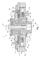
- the single FIGURE shows a schematically illustrated section along the axis of rotation through a friction clutch according to the invention.
- an electromagnetic friction clutch 1 is shown, which is designed for the drive of a fan, not shown.
- the coupling 1 has an annular housing 2. Walls 2a, 2b, 2c enclose an annular chamber in the housing 2, in which an electromagnetic coil 3 is housed. About a passage 15, the solenoid coil is connected to an electrical power supply.
- the annular chamber 2d is covered by a disk rotor 4 on a fourth side whose surface is perpendicular to a coupling rotational axis 17.
- the disk rotor 4 is mounted on a rotary shaft 10.
- the rotary shaft 10 is freely rotatably mounted by means of the ball bearing 13 a, which sits at the inner diameter of the annular housing 2.
- the rotary shaft 10 in turn carries a coupling element 6, which is mounted concentrically and freely rotatably by means of a ball bearing 13b in the bearing sleeve 6d both to the housing 2 and to the disc rotor 4.
- the coupling element 6 is provided as an output flange for attaching a fan.
- the rotary shaft 10 is formed as a hollow shaft and has a thread 10b, in which a clamping screw 11 is screwed.
- a Clamping ring 12a and the spacer rings 12b and 12c With help of a Clamping ring 12a and the spacer rings 12b and 12c, the disc rotor 4 and the ball bearings 13b and 13a arranged in the axial direction to each other so that the clutch housing 2, the disc rotor 4 and the coupling element 6 are freely rotatably mounted to each other freely.
- an armature disk 8 is mounted on the coupling element 6 on the disk rotor 4 side facing axially movable. Therefore, when current-carrying coil 3, the armature disc 8 is tightened axially against the force of the springs 9 to the disc rotor 4.
- Both the rotor 4 and the armature disk 8 have a plurality of annular concentric with the coupling axis of rotation 17 arranged segments 4, 4a, 4b, 8, 8a, which are radially offset from each other so that the magnetic flux generated by the electromagnet 3 alternately the armature disk 8 and the Disk rotor 4 flows through.
- the outer annular wall 2 b of the coupling housing 2 is pulled higher in the axial direction relative to the inner annular wall 2 a, so that the annular wall 2 b surrounds the lateral surface of the rotor 4 without contact.
- the clutch is actuated, therefore, the outermost edge of the rotor 4 is hardly moved in the axial direction, and mechanical stresses in the disk rotor 4 are largely avoided in the engaged state.
- annular eddy current element 5 On the armature disk 8 facing side of the rotor 4, an annular eddy current element 5 is mounted concentrically to the coupling axis of rotation at the outermost segment 4a.
- the eddy current ring 5 may be glued or screwed to the rotor segment 4a, for example.
- heat sinks 5a are formed on the eddy current ring 5 in such a way that they start from the eddy current ring 5 in the axial direction Direction along the clutch housing 2 on the outside contactlessly extend. Due to the comparatively simple geometry of the eddy current ring 5 and the heat sink 5 a, these can advantageously be produced in one piece together, for example, with inexpensive casting molds.
- the mentioned example of a manufacturing method also offers the possibility of additionally inserting into the eddy current ring 5 a flat steel ring (not shown) in the eddy current ring 5 in order to amplify the excitation of eddy currents by an improved magnetic inference.
- magnets 7 are attached to the coupling element 6 on an outer ring area 6a, which is located within a radial area to the coupling axis of rotation 17 defined by the eddy current ring 5.
- the magnets 7 induce eddy currents through the magnetic retroactivity of which a torque is transmitted, for example, from the eddy current ring 5 to the output element 6.
- the coupling element 6 is designed on its axially outwardly directed from the coupling side as output flange.
- a fan wheel can be fastened to the coupling element 6 with the aid of the screw bolts 16 at an annular region 6b.
- a centering 6c supports the attachment of the hub of a fan coaxial with the coupling axis of rotation to avoid imbalance and related vibrations. Since there are no or only low requirements for heat dissipation for the coupling element 6, the centering ring 6c can run comparatively close to the bearing sleeve 6d, so that fan wheels with a correspondingly small centering diameter can be attached.
Landscapes
- Engineering & Computer Science (AREA)
- General Engineering & Computer Science (AREA)
- Physics & Mathematics (AREA)
- Electromagnetism (AREA)
- Mechanical Engineering (AREA)
- Dynamo-Electric Clutches, Dynamo-Electric Brakes (AREA)
Applications Claiming Priority (1)
| Application Number | Priority Date | Filing Date | Title |
|---|---|---|---|
| DE102009033179A DE102009033179A1 (de) | 2009-07-13 | 2009-07-13 | Elektromagnetische Reibschaltkupplung |
Publications (3)
| Publication Number | Publication Date |
|---|---|
| EP2275700A2 true EP2275700A2 (fr) | 2011-01-19 |
| EP2275700A3 EP2275700A3 (fr) | 2011-10-26 |
| EP2275700B1 EP2275700B1 (fr) | 2014-11-12 |
Family
ID=43003483
Family Applications (1)
| Application Number | Title | Priority Date | Filing Date |
|---|---|---|---|
| EP10005230.7A Not-in-force EP2275700B1 (fr) | 2009-07-13 | 2010-05-19 | Embrayage à friction électromagnétique |
Country Status (3)
| Country | Link |
|---|---|
| US (1) | US8573375B2 (fr) |
| EP (1) | EP2275700B1 (fr) |
| DE (1) | DE102009033179A1 (fr) |
Cited By (1)
| Publication number | Priority date | Publication date | Assignee | Title |
|---|---|---|---|---|
| CN103437878A (zh) * | 2013-09-05 | 2013-12-11 | 浙江耐士伦机械有限公司 | 重卡扭转减震电磁离合器总成 |
Families Citing this family (2)
| Publication number | Priority date | Publication date | Assignee | Title |
|---|---|---|---|---|
| FR2978319B1 (fr) * | 2011-07-20 | 2013-07-05 | Enensys Technologies | Systeme de diffusion de programmes videos |
| DE112015002180A5 (de) * | 2014-05-09 | 2017-01-26 | Schaeffler Technologies AG & Co. KG | Kupplungseinrichtung mit Wirbelstrombremse mit reduziertem Luftspalt |
Family Cites Families (7)
| Publication number | Priority date | Publication date | Assignee | Title |
|---|---|---|---|---|
| US6634476B2 (en) * | 2000-10-20 | 2003-10-21 | Usui Kokusai Sangyo Kaisha, Limited | Magnet type fan clutch apparatus |
| EP1353051B1 (fr) * | 2002-04-08 | 2007-07-18 | Baruffaldi S.p.A. | Dispositif pour commander l'arbre d'actionnement d'une pompe de fluide de refroidissement pour des moteurs à combustion interne de véhicule |
| JP2004308903A (ja) * | 2003-04-07 | 2004-11-04 | Luk Lamellen & Kupplungsbau Beteiligungs Kg | 電磁式の摩擦クラッチ |
| ITMI20040487A1 (it) * | 2004-03-16 | 2004-06-16 | Baruffaldi Spa | Dispositvo di trasmissione del moto a ventole di raffreddamento di motori dotato di mezzi di arresto della ventola corrispondente ad una condizione di folle della stessa |
| JP2006162047A (ja) * | 2004-12-10 | 2006-06-22 | Usui Kokusai Sangyo Kaisha Ltd | マグネット式ファンクラッチの制御方法 |
| DE102005036418A1 (de) * | 2005-07-29 | 2007-02-08 | Linnig Trucktec Gmbh | Elektromagnetisch betätigbare Reibscheibenkupplung und Rotor für eine solche Kupplung |
| DE102008016277A1 (de) * | 2008-03-28 | 2009-10-01 | Linnig Trucktec Gmbh | Elektromagnetisch betätigbare Kupplung sowie Wasserpumpe mit einer elektromagnetisch betätigbaren Kupplung |
-
2009
- 2009-07-13 DE DE102009033179A patent/DE102009033179A1/de not_active Withdrawn
-
2010
- 2010-05-19 EP EP10005230.7A patent/EP2275700B1/fr not_active Not-in-force
- 2010-07-13 US US12/835,120 patent/US8573375B2/en not_active Expired - Fee Related
Non-Patent Citations (1)
| Title |
|---|
| None |
Cited By (2)
| Publication number | Priority date | Publication date | Assignee | Title |
|---|---|---|---|---|
| CN103437878A (zh) * | 2013-09-05 | 2013-12-11 | 浙江耐士伦机械有限公司 | 重卡扭转减震电磁离合器总成 |
| CN103437878B (zh) * | 2013-09-05 | 2016-01-20 | 浙江耐士伦机械有限公司 | 重卡扭转减震电磁离合器总成 |
Also Published As
| Publication number | Publication date |
|---|---|
| US20110005887A1 (en) | 2011-01-13 |
| DE102009033179A1 (de) | 2011-01-27 |
| US8573375B2 (en) | 2013-11-05 |
| EP2275700A3 (fr) | 2011-10-26 |
| EP2275700B1 (fr) | 2014-11-12 |
Similar Documents
| Publication | Publication Date | Title |
|---|---|---|
| EP2633603B1 (fr) | Moteur électrique | |
| EP2275701B1 (fr) | Embrayage à friction électromagnétique | |
| EP2633604B1 (fr) | Ensemble pour la fabrication de moteurs électriques différents d'une série de moteurs électriques et procédé de fabrication | |
| DE102010047945A1 (de) | Kupplungsmechanismus und Kupplungssystem mit diesem | |
| DE3327123A1 (de) | Antriebsanordnung fuer signalverarbeitende geraete | |
| DE102010049744A1 (de) | Bremse | |
| EP2061141B1 (fr) | Machine électrique dotée de freins magnétiques directement sur le rotor | |
| DE10150175A1 (de) | Magnetische Lüfterkupplung | |
| EP1922799B1 (fr) | Entrainement electrique a induit en pot et elements magnetiques permanents exterieurs | |
| EP2275700B1 (fr) | Embrayage à friction électromagnétique | |
| EP2262989B1 (fr) | Embrayage à friction et système d entraînement pour le refroidissement d un moteur à combustion d un véhicule équipé d un embrayage à friction | |
| DE102014203944A1 (de) | Läufereinheit für eine elektrische Maschine sowie elektrische Maschine | |
| EP2138735A2 (fr) | Embrayage à friction destiné à la transmission de couple | |
| EP0111350B1 (fr) | Moteur électrique équipé d'un frein d'arrêt | |
| EP2822150B1 (fr) | Machine électrique dotée d'un couplage intégré | |
| DE3508227C1 (de) | Elektromagnetisch betaetigbare Reibungsbrems- und Kupplungsvorrichtung fuer einen elektromotorischen Antrieb,insbesondere fuer Industrie-Naehmaschinen | |
| EP4256199B1 (fr) | Agencement d'engrenage et de générateur comprenant un frein pour éolienne | |
| DE102014012348B4 (de) | Elektromotor, aufweisend einen Stator und einen Rotor, und Verfahren zum Herstellen einer elektromotorisch angetriebenen Maschine | |
| DE10103736C2 (de) | Elektromagnetisch lüftbare Federkraftbremse mit einem gegen einen Widerlagerflansch pressbaren Bremsrotor | |
| DE102014001023B4 (de) | Elektrische Maschine | |
| EP4684465A1 (fr) | Frein à actionnement électromagnétique et moteur électrique équipé d'un frein à actionnement électromagnétique | |
| DE102024110431A1 (de) | Elektromotor mit elektromagnetisch betätigbarer Bremse | |
| WO2025256945A1 (fr) | Dispositif de freinage, utilisation d'un dispositif de freinage, véhicule équipé d'un dispositif de freinage et banc d'essai de véhicule | |
| WO2026057322A1 (fr) | Ensemble frein à actionnement électromagnétique pourvu d'un arbre à freiner | |
| EP4666374A1 (fr) | Frein à actionnement électromagnétique et moteur électrique équipé d'un frein à actionnement électromagnétique |
Legal Events
| Date | Code | Title | Description |
|---|---|---|---|
| PUAI | Public reference made under article 153(3) epc to a published international application that has entered the european phase |
Free format text: ORIGINAL CODE: 0009012 |
|
| AK | Designated contracting states |
Kind code of ref document: A2 Designated state(s): AL AT BE BG CH CY CZ DE DK EE ES FI FR GB GR HR HU IE IS IT LI LT LU LV MC MK MT NL NO PL PT RO SE SI SK SM TR |
|
| AX | Request for extension of the european patent |
Extension state: BA ME RS |
|
| PUAL | Search report despatched |
Free format text: ORIGINAL CODE: 0009013 |
|
| AK | Designated contracting states |
Kind code of ref document: A3 Designated state(s): AL AT BE BG CH CY CZ DE DK EE ES FI FR GB GR HR HU IE IS IT LI LT LU LV MC MK MT NL NO PL PT RO SE SI SK SM TR |
|
| AX | Request for extension of the european patent |
Extension state: BA ME RS |
|
| RIC1 | Information provided on ipc code assigned before grant |
Ipc: F16D 27/112 20060101AFI20110921BHEP |
|
| 17P | Request for examination filed |
Effective date: 20120416 |
|
| 17Q | First examination report despatched |
Effective date: 20120705 |
|
| GRAP | Despatch of communication of intention to grant a patent |
Free format text: ORIGINAL CODE: EPIDOSNIGR1 |
|
| INTG | Intention to grant announced |
Effective date: 20140630 |
|
| RIN1 | Information on inventor provided before grant (corrected) |
Inventor name: DANGEL, JUERGEN Inventor name: KRAFFT, RAINER |
|
| GRAS | Grant fee paid |
Free format text: ORIGINAL CODE: EPIDOSNIGR3 |
|
| GRAA | (expected) grant |
Free format text: ORIGINAL CODE: 0009210 |
|
| AK | Designated contracting states |
Kind code of ref document: B1 Designated state(s): AL AT BE BG CH CY CZ DE DK EE ES FI FR GB GR HR HU IE IS IT LI LT LU LV MC MK MT NL NO PL PT RO SE SI SK SM TR |
|
| REG | Reference to a national code |
Ref country code: GB Ref legal event code: FG4D Free format text: NOT ENGLISH |
|
| REG | Reference to a national code |
Ref country code: CH Ref legal event code: EP |
|
| REG | Reference to a national code |
Ref country code: AT Ref legal event code: REF Ref document number: 695964 Country of ref document: AT Kind code of ref document: T Effective date: 20141115 |
|
| REG | Reference to a national code |
Ref country code: IE Ref legal event code: FG4D Free format text: LANGUAGE OF EP DOCUMENT: GERMAN |
|
| REG | Reference to a national code |
Ref country code: DE Ref legal event code: R096 Ref document number: 502010008219 Country of ref document: DE Effective date: 20141224 |
|
| REG | Reference to a national code |
Ref country code: NL Ref legal event code: VDEP Effective date: 20141112 |
|
| PG25 | Lapsed in a contracting state [announced via postgrant information from national office to epo] |
Ref country code: PT Free format text: LAPSE BECAUSE OF FAILURE TO SUBMIT A TRANSLATION OF THE DESCRIPTION OR TO PAY THE FEE WITHIN THE PRESCRIBED TIME-LIMIT Effective date: 20150312 Ref country code: NL Free format text: LAPSE BECAUSE OF FAILURE TO SUBMIT A TRANSLATION OF THE DESCRIPTION OR TO PAY THE FEE WITHIN THE PRESCRIBED TIME-LIMIT Effective date: 20141112 Ref country code: ES Free format text: LAPSE BECAUSE OF FAILURE TO SUBMIT A TRANSLATION OF THE DESCRIPTION OR TO PAY THE FEE WITHIN THE PRESCRIBED TIME-LIMIT Effective date: 20141112 Ref country code: IS Free format text: LAPSE BECAUSE OF FAILURE TO SUBMIT A TRANSLATION OF THE DESCRIPTION OR TO PAY THE FEE WITHIN THE PRESCRIBED TIME-LIMIT Effective date: 20150312 Ref country code: NO Free format text: LAPSE BECAUSE OF FAILURE TO SUBMIT A TRANSLATION OF THE DESCRIPTION OR TO PAY THE FEE WITHIN THE PRESCRIBED TIME-LIMIT Effective date: 20150212 Ref country code: FI Free format text: LAPSE BECAUSE OF FAILURE TO SUBMIT A TRANSLATION OF THE DESCRIPTION OR TO PAY THE FEE WITHIN THE PRESCRIBED TIME-LIMIT Effective date: 20141112 Ref country code: LT Free format text: LAPSE BECAUSE OF FAILURE TO SUBMIT A TRANSLATION OF THE DESCRIPTION OR TO PAY THE FEE WITHIN THE PRESCRIBED TIME-LIMIT Effective date: 20141112 |
|
| PG25 | Lapsed in a contracting state [announced via postgrant information from national office to epo] |
Ref country code: LV Free format text: LAPSE BECAUSE OF FAILURE TO SUBMIT A TRANSLATION OF THE DESCRIPTION OR TO PAY THE FEE WITHIN THE PRESCRIBED TIME-LIMIT Effective date: 20141112 Ref country code: GR Free format text: LAPSE BECAUSE OF FAILURE TO SUBMIT A TRANSLATION OF THE DESCRIPTION OR TO PAY THE FEE WITHIN THE PRESCRIBED TIME-LIMIT Effective date: 20150213 Ref country code: PL Free format text: LAPSE BECAUSE OF FAILURE TO SUBMIT A TRANSLATION OF THE DESCRIPTION OR TO PAY THE FEE WITHIN THE PRESCRIBED TIME-LIMIT Effective date: 20141112 Ref country code: CY Free format text: LAPSE BECAUSE OF FAILURE TO SUBMIT A TRANSLATION OF THE DESCRIPTION OR TO PAY THE FEE WITHIN THE PRESCRIBED TIME-LIMIT Effective date: 20141112 Ref country code: SE Free format text: LAPSE BECAUSE OF FAILURE TO SUBMIT A TRANSLATION OF THE DESCRIPTION OR TO PAY THE FEE WITHIN THE PRESCRIBED TIME-LIMIT Effective date: 20141112 Ref country code: HR Free format text: LAPSE BECAUSE OF FAILURE TO SUBMIT A TRANSLATION OF THE DESCRIPTION OR TO PAY THE FEE WITHIN THE PRESCRIBED TIME-LIMIT Effective date: 20141112 |
|
| PG25 | Lapsed in a contracting state [announced via postgrant information from national office to epo] |
Ref country code: RO Free format text: LAPSE BECAUSE OF FAILURE TO SUBMIT A TRANSLATION OF THE DESCRIPTION OR TO PAY THE FEE WITHIN THE PRESCRIBED TIME-LIMIT Effective date: 20141112 Ref country code: SK Free format text: LAPSE BECAUSE OF FAILURE TO SUBMIT A TRANSLATION OF THE DESCRIPTION OR TO PAY THE FEE WITHIN THE PRESCRIBED TIME-LIMIT Effective date: 20141112 Ref country code: DK Free format text: LAPSE BECAUSE OF FAILURE TO SUBMIT A TRANSLATION OF THE DESCRIPTION OR TO PAY THE FEE WITHIN THE PRESCRIBED TIME-LIMIT Effective date: 20141112 Ref country code: CZ Free format text: LAPSE BECAUSE OF FAILURE TO SUBMIT A TRANSLATION OF THE DESCRIPTION OR TO PAY THE FEE WITHIN THE PRESCRIBED TIME-LIMIT Effective date: 20141112 Ref country code: EE Free format text: LAPSE BECAUSE OF FAILURE TO SUBMIT A TRANSLATION OF THE DESCRIPTION OR TO PAY THE FEE WITHIN THE PRESCRIBED TIME-LIMIT Effective date: 20141112 |
|
| REG | Reference to a national code |
Ref country code: DE Ref legal event code: R097 Ref document number: 502010008219 Country of ref document: DE |
|
| PLBE | No opposition filed within time limit |
Free format text: ORIGINAL CODE: 0009261 |
|
| STAA | Information on the status of an ep patent application or granted ep patent |
Free format text: STATUS: NO OPPOSITION FILED WITHIN TIME LIMIT |
|
| 26N | No opposition filed |
Effective date: 20150813 |
|
| PG25 | Lapsed in a contracting state [announced via postgrant information from national office to epo] |
Ref country code: IT Free format text: LAPSE BECAUSE OF FAILURE TO SUBMIT A TRANSLATION OF THE DESCRIPTION OR TO PAY THE FEE WITHIN THE PRESCRIBED TIME-LIMIT Effective date: 20141112 |
|
| REG | Reference to a national code |
Ref country code: CH Ref legal event code: PL |
|
| GBPC | Gb: european patent ceased through non-payment of renewal fee |
Effective date: 20150519 |
|
| PG25 | Lapsed in a contracting state [announced via postgrant information from national office to epo] |
Ref country code: LI Free format text: LAPSE BECAUSE OF NON-PAYMENT OF DUE FEES Effective date: 20150531 Ref country code: MC Free format text: LAPSE BECAUSE OF FAILURE TO SUBMIT A TRANSLATION OF THE DESCRIPTION OR TO PAY THE FEE WITHIN THE PRESCRIBED TIME-LIMIT Effective date: 20141112 Ref country code: LU Free format text: LAPSE BECAUSE OF FAILURE TO SUBMIT A TRANSLATION OF THE DESCRIPTION OR TO PAY THE FEE WITHIN THE PRESCRIBED TIME-LIMIT Effective date: 20150519 Ref country code: CH Free format text: LAPSE BECAUSE OF NON-PAYMENT OF DUE FEES Effective date: 20150531 |
|
| REG | Reference to a national code |
Ref country code: IE Ref legal event code: MM4A |
|
| REG | Reference to a national code |
Ref country code: FR Ref legal event code: ST Effective date: 20160129 |
|
| PG25 | Lapsed in a contracting state [announced via postgrant information from national office to epo] |
Ref country code: SI Free format text: LAPSE BECAUSE OF FAILURE TO SUBMIT A TRANSLATION OF THE DESCRIPTION OR TO PAY THE FEE WITHIN THE PRESCRIBED TIME-LIMIT Effective date: 20141112 |
|
| PG25 | Lapsed in a contracting state [announced via postgrant information from national office to epo] |
Ref country code: IE Free format text: LAPSE BECAUSE OF NON-PAYMENT OF DUE FEES Effective date: 20150519 Ref country code: GB Free format text: LAPSE BECAUSE OF NON-PAYMENT OF DUE FEES Effective date: 20150519 |
|
| PG25 | Lapsed in a contracting state [announced via postgrant information from national office to epo] |
Ref country code: FR Free format text: LAPSE BECAUSE OF NON-PAYMENT OF DUE FEES Effective date: 20150601 |
|
| REG | Reference to a national code |
Ref country code: AT Ref legal event code: MM01 Ref document number: 695964 Country of ref document: AT Kind code of ref document: T Effective date: 20150519 |
|
| PG25 | Lapsed in a contracting state [announced via postgrant information from national office to epo] |
Ref country code: AT Free format text: LAPSE BECAUSE OF NON-PAYMENT OF DUE FEES Effective date: 20150519 |
|
| PG25 | Lapsed in a contracting state [announced via postgrant information from national office to epo] |
Ref country code: MT Free format text: LAPSE BECAUSE OF FAILURE TO SUBMIT A TRANSLATION OF THE DESCRIPTION OR TO PAY THE FEE WITHIN THE PRESCRIBED TIME-LIMIT Effective date: 20141112 |
|
| PG25 | Lapsed in a contracting state [announced via postgrant information from national office to epo] |
Ref country code: BG Free format text: LAPSE BECAUSE OF FAILURE TO SUBMIT A TRANSLATION OF THE DESCRIPTION OR TO PAY THE FEE WITHIN THE PRESCRIBED TIME-LIMIT Effective date: 20141112 Ref country code: HU Free format text: LAPSE BECAUSE OF FAILURE TO SUBMIT A TRANSLATION OF THE DESCRIPTION OR TO PAY THE FEE WITHIN THE PRESCRIBED TIME-LIMIT; INVALID AB INITIO Effective date: 20100519 Ref country code: SM Free format text: LAPSE BECAUSE OF FAILURE TO SUBMIT A TRANSLATION OF THE DESCRIPTION OR TO PAY THE FEE WITHIN THE PRESCRIBED TIME-LIMIT Effective date: 20141112 |
|
| PG25 | Lapsed in a contracting state [announced via postgrant information from national office to epo] |
Ref country code: BE Free format text: LAPSE BECAUSE OF NON-PAYMENT OF DUE FEES Effective date: 20150531 |
|
| PG25 | Lapsed in a contracting state [announced via postgrant information from national office to epo] |
Ref country code: TR Free format text: LAPSE BECAUSE OF FAILURE TO SUBMIT A TRANSLATION OF THE DESCRIPTION OR TO PAY THE FEE WITHIN THE PRESCRIBED TIME-LIMIT Effective date: 20141112 |
|
| PG25 | Lapsed in a contracting state [announced via postgrant information from national office to epo] |
Ref country code: MK Free format text: LAPSE BECAUSE OF FAILURE TO SUBMIT A TRANSLATION OF THE DESCRIPTION OR TO PAY THE FEE WITHIN THE PRESCRIBED TIME-LIMIT Effective date: 20141112 |
|
| PG25 | Lapsed in a contracting state [announced via postgrant information from national office to epo] |
Ref country code: AL Free format text: LAPSE BECAUSE OF FAILURE TO SUBMIT A TRANSLATION OF THE DESCRIPTION OR TO PAY THE FEE WITHIN THE PRESCRIBED TIME-LIMIT Effective date: 20141112 |
|
| PGFP | Annual fee paid to national office [announced via postgrant information from national office to epo] |
Ref country code: DE Payment date: 20190606 Year of fee payment: 10 |
|
| REG | Reference to a national code |
Ref country code: DE Ref legal event code: R119 Ref document number: 502010008219 Country of ref document: DE |
|
| PG25 | Lapsed in a contracting state [announced via postgrant information from national office to epo] |
Ref country code: DE Free format text: LAPSE BECAUSE OF NON-PAYMENT OF DUE FEES Effective date: 20201201 |