EP2276149B1 - Wicklungsschema für einen segmentierten Ständer einer dynamoelektrischen Maschine - Google Patents
Wicklungsschema für einen segmentierten Ständer einer dynamoelektrischen Maschine Download PDFInfo
- Publication number
- EP2276149B1 EP2276149B1 EP10164078.7A EP10164078A EP2276149B1 EP 2276149 B1 EP2276149 B1 EP 2276149B1 EP 10164078 A EP10164078 A EP 10164078A EP 2276149 B1 EP2276149 B1 EP 2276149B1
- Authority
- EP
- European Patent Office
- Prior art keywords
- segment
- coils
- segments
- stator
- coil
- Prior art date
- Legal status (The legal status is an assumption and is not a legal conclusion. Google has not performed a legal analysis and makes no representation as to the accuracy of the status listed.)
- Active
Links
Images


Classifications
-
- H—ELECTRICITY
- H02—GENERATION; CONVERSION OR DISTRIBUTION OF ELECTRIC POWER
- H02K—DYNAMO-ELECTRIC MACHINES
- H02K3/00—Details of windings
- H02K3/04—Windings characterised by the conductor shape, form or construction, e.g. with bar conductors
- H02K3/28—Layout of windings or of connections between windings
-
- H—ELECTRICITY
- H02—GENERATION; CONVERSION OR DISTRIBUTION OF ELECTRIC POWER
- H02K—DYNAMO-ELECTRIC MACHINES
- H02K1/00—Details of the magnetic circuit
- H02K1/06—Details of the magnetic circuit characterised by the shape, form or construction
- H02K1/12—Stationary parts of the magnetic circuit
- H02K1/14—Stator cores with salient poles
- H02K1/146—Stator cores with salient poles consisting of a generally annular yoke with salient poles
- H02K1/148—Sectional cores
-
- H—ELECTRICITY
- H02—GENERATION; CONVERSION OR DISTRIBUTION OF ELECTRIC POWER
- H02K—DYNAMO-ELECTRIC MACHINES
- H02K2213/00—Specific aspects, not otherwise provided for and not covered by codes H02K2201/00 - H02K2211/00
- H02K2213/12—Machines characterised by the modularity of some components
-
- H—ELECTRICITY
- H02—GENERATION; CONVERSION OR DISTRIBUTION OF ELECTRIC POWER
- H02K—DYNAMO-ELECTRIC MACHINES
- H02K7/00—Arrangements for handling mechanical energy structurally associated with dynamo-electric machines, e.g. structural association with mechanical driving motors or auxiliary dynamo-electric machines
- H02K7/18—Structural association of electric generators with mechanical driving motors, e.g. with turbines
- H02K7/1807—Rotary generators
- H02K7/1823—Rotary generators structurally associated with turbines or similar engines
- H02K7/183—Rotary generators structurally associated with turbines or similar engines wherein the turbine is a wind turbine
- H02K7/1838—Generators mounted in a nacelle or similar structure of a horizontal axis wind turbine
-
- Y—GENERAL TAGGING OF NEW TECHNOLOGICAL DEVELOPMENTS; GENERAL TAGGING OF CROSS-SECTIONAL TECHNOLOGIES SPANNING OVER SEVERAL SECTIONS OF THE IPC; TECHNICAL SUBJECTS COVERED BY FORMER USPC CROSS-REFERENCE ART COLLECTIONS [XRACs] AND DIGESTS
- Y02—TECHNOLOGIES OR APPLICATIONS FOR MITIGATION OR ADAPTATION AGAINST CLIMATE CHANGE
- Y02E—REDUCTION OF GREENHOUSE GAS [GHG] EMISSIONS, RELATED TO ENERGY GENERATION, TRANSMISSION OR DISTRIBUTION
- Y02E10/00—Energy generation through renewable energy sources
- Y02E10/70—Wind energy
- Y02E10/72—Wind turbines with rotation axis in wind direction
Definitions
- the invention relates to a segment for an annular stator of a dynamo-electric machine.
- the invention is used in particular in very large electrical machines.
- Generators for wind turbines, tidal power plants, ring motors or drives for construction machinery such as excavators are examples of such machines.
- gearless wind turbines become competitive compared to systems in which a mechanical gear is connected between the rotor blades driven by the wind and a synchronous generator.
- the main advantage of such a gearless design is the significantly simpler structure compared to wind turbines with gearboxes. By saving the gear, fewer rotating machine components are required. This results in a reduced maintenance effort and an increased availability of the system.
- Generators for gearless wind turbines are often designed with an annular rotor with a hollow shaft.
- Such an electrical machine is, for example, from WO 2006/032969 A2 known.
- This document discloses a stator which is divided into several segments in the circumferential device. Each stator segment comprises a dovetail-shaped profile which engages in a window of a stator ring. In this way, each of these sectors can be pulled out in the axial direction without the entire stator having to be removed.
- EP 1 093 207 A2 , DE 10 2005 029895 A1 and EP 1 780 869 A2 disclose segments for an annular stator of a dynamo-electric machine.
- EP 2 166 645 A1 discloses an elongated end joint.
- the invention is based on the knowledge that the problematic electrical connections described above between the individual segments of the stator can be eliminated if all coils of a segment are closed within the segment. This means that the coils arranged at the segment boundaries are also closed within the segment. This is made possible in that the first conductor arranged at the first segment boundary is connected to the second conductor arranged at the second segment boundary via an extended end connection on the end winding. This means that the first conductor does not have to be connected to a further conductor of an adjacent further segment across the left segment boundary. Rather, the back ladder for the first ladder is the second ladder, which is located on the right segment boundary.
- the segment according to the invention therefore comprises at least three coils.
- the segment can be impregnated as a complete, self-contained unit. Subsequent coil connections across the segment boundaries are not required.
- the resulting segments according to the invention can be mounted as closed functional elements and, for example, for Dismantled for maintenance or repair purposes. Instead of a complete stand, a single segment can be kept as a spare part.
- the electrical machine according to the invention can be both a generator and a motor.
- the segmentation of the stator according to the invention is particularly advantageous in the case of very large bore diameters, regardless of whether the machine is primarily intended for motor or generator use.
- the coils can be supplied with a three-phase current independently of further coils of the further segments in order to generate a first pole pair of a rotating field.
- the segment can also have more coils, so that with their help a higher number of pole pairs than one can be generated.
- An embodiment of the invention is advantageous in which the segment for each phase of the three-phase system has at least one second coil closed within the segment for generating a second pole pair, which is independent of further coils of the further segments for generating a second pole pair of the rotary field with the three-phase current can be energized.
- windings expediently designed as circumferential windings, are designed in an advantageous embodiment of the invention in such a way that the coils are arranged as tier windings so that the conductors of the three coils of a pole pair are superimposed in the area of the winding heads.
- a simple production of such a segment is given in a further advantageous embodiment of the invention in that the coils are designed as single-layer windings.
- An embodiment of the invention is also advantageous in which a dynamoelectric machine with at least two segments of one of the embodiments described above is designed as a directly driven generator for a wind power plant or a tidal power plant. Generators of this type require a large structural volume in order to deliver high electrical power due to the low speeds that can be generated with the drive forces used here. It is also advantageous to use an electrodynamic machine with a segmented stator according to an embodiment of the invention in numerous other areas of application that require a large torque and thus a large machine diameter.
- a wind power plant with a dynamo-electric machine the stator of which is made from individual, partially annular segments of one of the embodiments described above, can be installed very easily at its later place of use. Compared to a complete dynamo-electric machine, the individual segments of the stator can be transported much better to the installation site, for example by road.
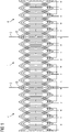
- FIG 1 shows a winding scheme for a segment 1 of a stator of conventional design, which is not part of the claimed invention.
- the winding scheme shown is implemented in a very large dynamoelectric machine, the stator of which is segmented in order to reduce its transport volume to such an extent that the stator can be transported over the road to a later place of use and installed there.
- a typical example of such a dynamo-electric machine is a wind power generator which is designed as a hollow shaft generator.
- An Indian FIG 1 Segment 1 shown in the center is connected to two further segments 4 during the assembly of the wind power generator.
- the further segments 4 adjoin segment 1 at a first and second segment boundary 2, 3.
- the segment 1 and the other segments 4 are largely identical in construction.
- Each of the segments is designed with coils that enable the generation of a rotating field. However, not all coils within segment 1 are closed.
- At the first segment boundary 2 and at the second segment boundary 3 there is a half-coil in each case, which must be electrically connected to a half-coil of one of the further segments 4.
- special connecting coils 15 are used, which over the said half-coils electrically connect the segment boundaries 2, 3. These must still have a certain flexibility in the spool nose.
- the connection coils 15 cannot be insulated as part of the impregnation process of the winding, but must be insulated by hand afterwards.
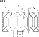
- FIG 2 shows a winding scheme for a segment 1 according to a first embodiment of the invention.
- the winding diagram or segment 1 is intended for a hollow shaft generator of a wind power plant.
- the segment 1 shown in the center is mechanically connected to further segments 4 at a first segment boundary 2 and a second segment boundary 3 during the construction of the wind power generator.
- N segments are provided for the hollow shaft generator, each of the segments 1 spans an arc of a circle with an angle of 360 ° / N with respect to its cross-sectional area.
- Each of the segments 1 comprises three coils 5,6,7 - one coil 5,6,7 for each phase of a three-phase system.
- a pole pair can thus be implemented with each segment 1 for the dynamo-electric machine.
- Two of these coils 5, 6, 7 are closed within segment 1 in a conventional manner.
- a third coil 5 is formed in that a first conductor 8, which is arranged in the vicinity of the first segment boundary 2, is connected via an end connection 10 to a second conductor 9, which is arranged in the vicinity of the second segment boundary 3.
- the coil 5 thus formed encloses the two conventionally closed coils 6, 7.
- the magnetic behavior of such a segment 1 essentially corresponds to a magnetic behavior as it is in a conventional winding according to FIG FIG 1 is achieved.
- FIG 3 shows a winding scheme for a segment 1 according to a second embodiment of the invention.
- three slots per pole and strand are provided here.
- the winding of these coils is analogous to that in FIG 2 shown winding executed. That is, here too, conductors 8, 9 arranged at segment boundaries 2, 3 are connected to one another via end connections 10.
- FIG 2 called.
- FIG 4 shows a wind turbine with a dynamo-electric machine which has a segmented stator.
- the electrical machine 14 is designed as a hollow shaft generator. A gear was dispensed with here, so that the stator of the dynamo-electric machine 14 has a very large diameter.
- the stator has a segmented structure so that it can be assembled at the later place of use by joining the individual segments together. Due to the advantageous configuration of these segments, which are an embodiment according to the present invention, the assembly of the hollow shaft generator is comparatively simple. An electrical connection between the individual segments is not necessary to energize the coils of the segments. This considerably simplifies assembly, since electrical segment connections are made afterwards be pulled between the coils of the segments on the construction site, would still have to be isolated in a complex manner. In contrast, the generator shown here consists of individual, fully electrically functional segments in which this connection is not required.
Landscapes
- Engineering & Computer Science (AREA)
- Power Engineering (AREA)
- Windings For Motors And Generators (AREA)
Applications Claiming Priority (1)
| Application Number | Priority Date | Filing Date | Title |
|---|---|---|---|
| DE102009032880A DE102009032880A1 (de) | 2009-07-13 | 2009-07-13 | Wicklungsschema für einen segmentierten Ständer einer dynamoelektrischen Maschine |
Publications (3)
| Publication Number | Publication Date |
|---|---|
| EP2276149A2 EP2276149A2 (de) | 2011-01-19 |
| EP2276149A3 EP2276149A3 (de) | 2016-11-09 |
| EP2276149B1 true EP2276149B1 (de) | 2021-04-21 |
Family
ID=42983613
Family Applications (1)
| Application Number | Title | Priority Date | Filing Date |
|---|---|---|---|
| EP10164078.7A Active EP2276149B1 (de) | 2009-07-13 | 2010-05-27 | Wicklungsschema für einen segmentierten Ständer einer dynamoelektrischen Maschine |
Country Status (5)
| Country | Link |
|---|---|
| US (1) | US8497614B2 (da) |
| EP (1) | EP2276149B1 (da) |
| DE (1) | DE102009032880A1 (da) |
| DK (1) | DK2276149T3 (da) |
| ES (1) | ES2875419T3 (da) |
Families Citing this family (6)
| Publication number | Priority date | Publication date | Assignee | Title |
|---|---|---|---|---|
| DE102009031371B4 (de) | 2009-07-01 | 2011-05-26 | Siemens Aktiengesellschaft | Läufer und Verfahren zur Herstellung eines Läufers einer elektrischen Maschine |
| ES2696544T3 (es) * | 2010-11-05 | 2019-01-16 | Vestas Wind Sys As | Generador segmentado de accionamiento directo |
| ES2428017T3 (es) | 2011-04-04 | 2013-11-05 | Siemens Aktiengesellschaft | Procedimiento para montar una máquina eléctrica |
| DE102012210614A1 (de) | 2012-06-22 | 2013-12-24 | Siemens Aktiengesellschaft | Verringerung des elektrischen Widerstandes bei einer elektrischen Maschine mit in Nuten angeordneten Wicklungen |
| US20170033631A1 (en) * | 2015-07-29 | 2017-02-02 | Siemens Energy, Inc. | Method for roebel transposition of form wound conductors of electrical machines such as generators and motors |
| EP4478587A1 (en) * | 2023-06-16 | 2024-12-18 | Siemens Gamesa Renewable Energy A/S | Stator of an electrical machine |
Family Cites Families (15)
| Publication number | Priority date | Publication date | Assignee | Title |
|---|---|---|---|---|
| US1799021A (en) * | 1926-04-16 | 1931-03-31 | Parsons | Electrical conductor |
| FR2208234B1 (da) * | 1972-11-27 | 1975-03-28 | Merlin Gerin | |
| US4103213A (en) * | 1976-09-16 | 1978-07-25 | Emerson Electric Co. | Two speed single phase induction motor |
| JP3484006B2 (ja) * | 1996-01-30 | 2004-01-06 | 株式会社日立製作所 | 回転機および成形方法 |
| US5811905A (en) * | 1997-01-07 | 1998-09-22 | Emerson Electric Co. | Doubly-fed switched reluctance machine |
| AT6706U1 (de) * | 1999-10-11 | 2004-02-25 | Innova Patent Gmbh | Elektromotor |
| JP2004282858A (ja) * | 2003-03-14 | 2004-10-07 | Hitachi Ltd | 固定子及びそれを用いた回転機 |
| ITBZ20040047A1 (it) | 2004-09-20 | 2004-12-20 | High Technology Invest Bv | Generatore/motore elettrico, in particolare per l'impiego in impianti eolici, impianti a fune o idraulici. |
| DE102005029895A1 (de) * | 2005-06-27 | 2007-01-04 | Siemens Ag | Direktantrieb für Großantriebe |
| US7348706B2 (en) * | 2005-10-31 | 2008-03-25 | A. O. Smith Corporation | Stator assembly for an electric machine and method of manufacturing the same |
| DE102006021354A1 (de) | 2006-05-08 | 2007-11-15 | Siemens Ag | Elektrische Maschine, insbesondere Synchronmotor, mit redundanten Statorwicklungen |
| US8222792B2 (en) * | 2006-08-04 | 2012-07-17 | Clean Current Limited Partnership | Axial air gap machine having stator and rotor discs formed of multiple detachable segments |
| US20090021093A1 (en) * | 2007-07-17 | 2009-01-22 | Taco, Inc. | Electric Motors |
| DE102007042338A1 (de) * | 2007-09-06 | 2009-03-12 | Siemens Ag | Windkraftanlage mit Wärmetauschersystem |
| ES2399454T3 (es) * | 2008-09-18 | 2013-04-01 | Siemens Aktiengesellschaft | Grupo de tres devanados de estator para un estator de una máquina eléctrica, disposición de estator, generador y turbina eólica |
-
2009
- 2009-07-13 DE DE102009032880A patent/DE102009032880A1/de not_active Withdrawn
-
2010
- 2010-05-27 ES ES10164078T patent/ES2875419T3/es active Active
- 2010-05-27 EP EP10164078.7A patent/EP2276149B1/de active Active
- 2010-05-27 DK DK10164078.7T patent/DK2276149T3/da active
- 2010-07-12 US US12/834,421 patent/US8497614B2/en active Active
Non-Patent Citations (1)
| Title |
|---|
| None * |
Also Published As
| Publication number | Publication date |
|---|---|
| EP2276149A3 (de) | 2016-11-09 |
| DE102009032880A1 (de) | 2011-01-20 |
| EP2276149A2 (de) | 2011-01-19 |
| ES2875419T3 (es) | 2021-11-10 |
| US20110163550A1 (en) | 2011-07-07 |
| DK2276149T3 (da) | 2021-06-28 |
| US8497614B2 (en) | 2013-07-30 |
Similar Documents
| Publication | Publication Date | Title |
|---|---|---|
| EP2508749B1 (de) | Verfahren zum Montieren einer elektrischen Maschine | |
| EP1574708B1 (de) | Windenergieanlage mit Ringgenerator | |
| EP3038233B1 (de) | Permanentmagnet-synchronmotor und elektrische servolenkung | |
| WO2011006810A2 (de) | Ringförmiger rotor für eine elektrische maschine | |
| EP3180838A1 (de) | Verfahren zum herstellen einer formspule für ein statorblechpaket | |
| DE102019103191A1 (de) | Stator für eine elektrische Maschine | |
| DE102007054719A1 (de) | Elektrische Drehfeldmaschine | |
| EP3455921B1 (de) | Synchrongenerator einer getriebelosen windenergieanlage sowie verfahren zum herstellen eines synchrongenerators | |
| EP2276149A2 (de) | Wicklungsschema für einen segmentierten Ständer einer dynamoelektrischen Maschine | |
| WO2019215097A1 (de) | Verfahren zum herstellen einer wicklung für einen ständer einer elektrischen machine und elektrische maschine | |
| WO2011006809A2 (de) | Segmentierter ständer für eine dynamoelektrische maschine | |
| DE102012214523B4 (de) | Ständer oder Ständersegment einer dynamoelektrischen Maschine mit optimiertem Wickelkopf, dynamoelektrische Maschine und Rohrmühle oder Windkraftgenerator | |
| WO2016023934A1 (de) | Verfahren zum herstellen eines bürstenkommutierten gleichstrommotors | |
| EP3100338B1 (de) | Zusammengesetzte elektrische maschine | |
| EP3048702A1 (de) | Rotor einer Reluktanzmaschine | |
| EP2436106B1 (de) | Verfahren zur herstellung einer ständerwicklung einer elektrischen maschine, insbesondere eines wechselstromgenerators | |
| WO2019149508A1 (de) | Rotor mit kühlkanälen | |
| DE102020203945A1 (de) | Statorwicklungssystem mit serieller Spulenwicklung | |
| EP4133573B1 (de) | Haltesystem für stromschienen an statoren bzw. statorsegmenten dynamoelektrischer maschinen | |
| WO2014184180A2 (de) | Bürstenkommutierter gleichstrommotor | |
| EP3007328A1 (de) | Aktivteil einer elektrischen Maschine | |
| DE102009001543A1 (de) | Elektrische Maschine und Verfahren zur Herstellung einer elektrischen Maschine | |
| DE102010028869A1 (de) | Dynamoelektrische Maschine mit einer Einschichtwicklung für Großantriebe | |
| DE102011084714A1 (de) | Elektrische Maschine | |
| EP3180841A1 (de) | Bürstenkommutierter gleichstrommotor |
Legal Events
| Date | Code | Title | Description |
|---|---|---|---|
| PUAI | Public reference made under article 153(3) epc to a published international application that has entered the european phase |
Free format text: ORIGINAL CODE: 0009012 |
|
| AK | Designated contracting states |
Kind code of ref document: A2 Designated state(s): AL AT BE BG CH CY CZ DE DK EE ES FI FR GB GR HR HU IE IS IT LI LT LU LV MC MK MT NL NO PL PT RO SE SI SK SM TR |
|
| AX | Request for extension of the european patent |
Extension state: BA ME RS |
|
| RAP1 | Party data changed (applicant data changed or rights of an application transferred) |
Owner name: SIEMENS AKTIENGESELLSCHAFT |
|
| PUAL | Search report despatched |
Free format text: ORIGINAL CODE: 0009013 |
|
| AK | Designated contracting states |
Kind code of ref document: A3 Designated state(s): AL AT BE BG CH CY CZ DE DK EE ES FI FR GB GR HR HU IE IS IT LI LT LU LV MC MK MT NL NO PL PT RO SE SI SK SM TR |
|
| AX | Request for extension of the european patent |
Extension state: BA ME RS |
|
| RIC1 | Information provided on ipc code assigned before grant |
Ipc: H02K 3/12 20060101AFI20160930BHEP |
|
| STAA | Information on the status of an ep patent application or granted ep patent |
Free format text: STATUS: REQUEST FOR EXAMINATION WAS MADE |
|
| 17P | Request for examination filed |
Effective date: 20170505 |
|
| RBV | Designated contracting states (corrected) |
Designated state(s): AL AT BE BG CH CY CZ DE DK EE ES FI FR GB GR HR HU IE IS IT LI LT LU LV MC MK MT NL NO PL PT RO SE SI SK SM TR |
|
| RAP1 | Party data changed (applicant data changed or rights of an application transferred) |
Owner name: SIEMENS AKTIENGESELLSCHAFT |
|
| STAA | Information on the status of an ep patent application or granted ep patent |
Free format text: STATUS: EXAMINATION IS IN PROGRESS |
|
| 17Q | First examination report despatched |
Effective date: 20200225 |
|
| REG | Reference to a national code |
Ref country code: DE Ref legal event code: R079 Ref document number: 502010016896 Country of ref document: DE Free format text: PREVIOUS MAIN CLASS: H02K0003120000 Ipc: H02K0003280000 |
|
| GRAP | Despatch of communication of intention to grant a patent |
Free format text: ORIGINAL CODE: EPIDOSNIGR1 |
|
| STAA | Information on the status of an ep patent application or granted ep patent |
Free format text: STATUS: GRANT OF PATENT IS INTENDED |
|
| RAP1 | Party data changed (applicant data changed or rights of an application transferred) |
Owner name: FLENDER GMBH |
|
| INTG | Intention to grant announced |
Effective date: 20201211 |
|
| RIC1 | Information provided on ipc code assigned before grant |
Ipc: H02K 7/18 20060101ALI20201130BHEP Ipc: H02K 3/28 20060101AFI20201130BHEP Ipc: H02K 1/14 20060101ALI20201130BHEP |
|
| GRAS | Grant fee paid |
Free format text: ORIGINAL CODE: EPIDOSNIGR3 |
|
| GRAA | (expected) grant |
Free format text: ORIGINAL CODE: 0009210 |
|
| STAA | Information on the status of an ep patent application or granted ep patent |
Free format text: STATUS: THE PATENT HAS BEEN GRANTED |
|
| AK | Designated contracting states |
Kind code of ref document: B1 Designated state(s): AL AT BE BG CH CY CZ DE DK EE ES FI FR GB GR HR HU IE IS IT LI LT LU LV MC MK MT NL NO PL PT RO SE SI SK SM TR |
|
| REG | Reference to a national code |
Ref country code: GB Ref legal event code: FG4D Free format text: NOT ENGLISH |
|
| REG | Reference to a national code |
Ref country code: CH Ref legal event code: EP |
|
| REG | Reference to a national code |
Ref country code: DE Ref legal event code: R096 Ref document number: 502010016896 Country of ref document: DE |
|
| REG | Reference to a national code |
Ref country code: IE Ref legal event code: FG4D Free format text: LANGUAGE OF EP DOCUMENT: GERMAN |
|
| REG | Reference to a national code |
Ref country code: AT Ref legal event code: REF Ref document number: 1385676 Country of ref document: AT Kind code of ref document: T Effective date: 20210515 |
|
| REG | Reference to a national code |
Ref country code: DK Ref legal event code: T3 Effective date: 20210621 |
|
| REG | Reference to a national code |
Ref country code: NL Ref legal event code: FP |
|
| REG | Reference to a national code |
Ref country code: FI Ref legal event code: FGE |
|
| REG | Reference to a national code |
Ref country code: SE Ref legal event code: TRGR |
|
| PGFP | Annual fee paid to national office [announced via postgrant information from national office to epo] |
Ref country code: NL Payment date: 20210617 Year of fee payment: 12 Ref country code: DE Payment date: 20210527 Year of fee payment: 12 Ref country code: FR Payment date: 20210617 Year of fee payment: 12 Ref country code: FI Payment date: 20210616 Year of fee payment: 12 |
|
| REG | Reference to a national code |
Ref country code: LT Ref legal event code: MG9D |
|
| PGFP | Annual fee paid to national office [announced via postgrant information from national office to epo] |
Ref country code: GB Payment date: 20210525 Year of fee payment: 12 Ref country code: DK Payment date: 20210623 Year of fee payment: 12 Ref country code: AT Payment date: 20210621 Year of fee payment: 12 Ref country code: SE Payment date: 20210618 Year of fee payment: 12 |
|
| REG | Reference to a national code |
Ref country code: EE Ref legal event code: FG4A Ref document number: E021178 Country of ref document: EE Effective date: 20210721 |
|
| PG25 | Lapsed in a contracting state [announced via postgrant information from national office to epo] |
Ref country code: LT Free format text: LAPSE BECAUSE OF FAILURE TO SUBMIT A TRANSLATION OF THE DESCRIPTION OR TO PAY THE FEE WITHIN THE PRESCRIBED TIME-LIMIT Effective date: 20210421 Ref country code: BG Free format text: LAPSE BECAUSE OF FAILURE TO SUBMIT A TRANSLATION OF THE DESCRIPTION OR TO PAY THE FEE WITHIN THE PRESCRIBED TIME-LIMIT Effective date: 20210721 Ref country code: HR Free format text: LAPSE BECAUSE OF FAILURE TO SUBMIT A TRANSLATION OF THE DESCRIPTION OR TO PAY THE FEE WITHIN THE PRESCRIBED TIME-LIMIT Effective date: 20210421 |
|
| PGFP | Annual fee paid to national office [announced via postgrant information from national office to epo] |
Ref country code: EE Payment date: 20210617 Year of fee payment: 12 |
|
| REG | Reference to a national code |
Ref country code: ES Ref legal event code: FG2A Ref document number: 2875419 Country of ref document: ES Kind code of ref document: T3 Effective date: 20211110 |
|
| PG25 | Lapsed in a contracting state [announced via postgrant information from national office to epo] |
Ref country code: IS Free format text: LAPSE BECAUSE OF FAILURE TO SUBMIT A TRANSLATION OF THE DESCRIPTION OR TO PAY THE FEE WITHIN THE PRESCRIBED TIME-LIMIT Effective date: 20210821 Ref country code: LV Free format text: LAPSE BECAUSE OF FAILURE TO SUBMIT A TRANSLATION OF THE DESCRIPTION OR TO PAY THE FEE WITHIN THE PRESCRIBED TIME-LIMIT Effective date: 20210421 Ref country code: GR Free format text: LAPSE BECAUSE OF FAILURE TO SUBMIT A TRANSLATION OF THE DESCRIPTION OR TO PAY THE FEE WITHIN THE PRESCRIBED TIME-LIMIT Effective date: 20210722 Ref country code: NO Free format text: LAPSE BECAUSE OF FAILURE TO SUBMIT A TRANSLATION OF THE DESCRIPTION OR TO PAY THE FEE WITHIN THE PRESCRIBED TIME-LIMIT Effective date: 20210721 Ref country code: PT Free format text: LAPSE BECAUSE OF FAILURE TO SUBMIT A TRANSLATION OF THE DESCRIPTION OR TO PAY THE FEE WITHIN THE PRESCRIBED TIME-LIMIT Effective date: 20210823 Ref country code: PL Free format text: LAPSE BECAUSE OF FAILURE TO SUBMIT A TRANSLATION OF THE DESCRIPTION OR TO PAY THE FEE WITHIN THE PRESCRIBED TIME-LIMIT Effective date: 20210421 |
|
| PGFP | Annual fee paid to national office [announced via postgrant information from national office to epo] |
Ref country code: ES Payment date: 20210721 Year of fee payment: 12 |
|
| REG | Reference to a national code |
Ref country code: CH Ref legal event code: PL |
|
| REG | Reference to a national code |
Ref country code: DE Ref legal event code: R097 Ref document number: 502010016896 Country of ref document: DE |
|
| PG25 | Lapsed in a contracting state [announced via postgrant information from national office to epo] |
Ref country code: CZ Free format text: LAPSE BECAUSE OF FAILURE TO SUBMIT A TRANSLATION OF THE DESCRIPTION OR TO PAY THE FEE WITHIN THE PRESCRIBED TIME-LIMIT Effective date: 20210421 Ref country code: SK Free format text: LAPSE BECAUSE OF FAILURE TO SUBMIT A TRANSLATION OF THE DESCRIPTION OR TO PAY THE FEE WITHIN THE PRESCRIBED TIME-LIMIT Effective date: 20210421 Ref country code: SM Free format text: LAPSE BECAUSE OF FAILURE TO SUBMIT A TRANSLATION OF THE DESCRIPTION OR TO PAY THE FEE WITHIN THE PRESCRIBED TIME-LIMIT Effective date: 20210421 Ref country code: MC Free format text: LAPSE BECAUSE OF FAILURE TO SUBMIT A TRANSLATION OF THE DESCRIPTION OR TO PAY THE FEE WITHIN THE PRESCRIBED TIME-LIMIT Effective date: 20210421 Ref country code: LU Free format text: LAPSE BECAUSE OF NON-PAYMENT OF DUE FEES Effective date: 20210527 Ref country code: LI Free format text: LAPSE BECAUSE OF NON-PAYMENT OF DUE FEES Effective date: 20210531 Ref country code: CH Free format text: LAPSE BECAUSE OF NON-PAYMENT OF DUE FEES Effective date: 20210531 Ref country code: RO Free format text: LAPSE BECAUSE OF FAILURE TO SUBMIT A TRANSLATION OF THE DESCRIPTION OR TO PAY THE FEE WITHIN THE PRESCRIBED TIME-LIMIT Effective date: 20210421 |
|
| REG | Reference to a national code |
Ref country code: BE Ref legal event code: MM Effective date: 20210531 |
|
| PLBE | No opposition filed within time limit |
Free format text: ORIGINAL CODE: 0009261 |
|
| STAA | Information on the status of an ep patent application or granted ep patent |
Free format text: STATUS: NO OPPOSITION FILED WITHIN TIME LIMIT |
|
| 26N | No opposition filed |
Effective date: 20220124 |
|
| PG25 | Lapsed in a contracting state [announced via postgrant information from national office to epo] |
Ref country code: IE Free format text: LAPSE BECAUSE OF NON-PAYMENT OF DUE FEES Effective date: 20210527 |
|
| PG25 | Lapsed in a contracting state [announced via postgrant information from national office to epo] |
Ref country code: IS Free format text: LAPSE BECAUSE OF FAILURE TO SUBMIT A TRANSLATION OF THE DESCRIPTION OR TO PAY THE FEE WITHIN THE PRESCRIBED TIME-LIMIT Effective date: 20210821 Ref country code: AL Free format text: LAPSE BECAUSE OF FAILURE TO SUBMIT A TRANSLATION OF THE DESCRIPTION OR TO PAY THE FEE WITHIN THE PRESCRIBED TIME-LIMIT Effective date: 20210421 |
|
| PG25 | Lapsed in a contracting state [announced via postgrant information from national office to epo] |
Ref country code: IT Free format text: LAPSE BECAUSE OF FAILURE TO SUBMIT A TRANSLATION OF THE DESCRIPTION OR TO PAY THE FEE WITHIN THE PRESCRIBED TIME-LIMIT Effective date: 20210421 Ref country code: BE Free format text: LAPSE BECAUSE OF NON-PAYMENT OF DUE FEES Effective date: 20210531 |
|
| REG | Reference to a national code |
Ref country code: DE Ref legal event code: R119 Ref document number: 502010016896 Country of ref document: DE |
|
| REG | Reference to a national code |
Ref country code: EE Ref legal event code: MM4A Ref document number: E021178 Country of ref document: EE Effective date: 20220531 |
|
| REG | Reference to a national code |
Ref country code: DK Ref legal event code: EBP Effective date: 20220531 |
|
| REG | Reference to a national code |
Ref country code: SE Ref legal event code: EUG |
|
| REG | Reference to a national code |
Ref country code: NL Ref legal event code: MM Effective date: 20220601 |
|
| REG | Reference to a national code |
Ref country code: AT Ref legal event code: MM01 Ref document number: 1385676 Country of ref document: AT Kind code of ref document: T Effective date: 20220527 |
|
| GBPC | Gb: european patent ceased through non-payment of renewal fee |
Effective date: 20220527 |
|
| PG25 | Lapsed in a contracting state [announced via postgrant information from national office to epo] |
Ref country code: SE Free format text: LAPSE BECAUSE OF NON-PAYMENT OF DUE FEES Effective date: 20220528 Ref country code: FI Free format text: LAPSE BECAUSE OF NON-PAYMENT OF DUE FEES Effective date: 20220527 Ref country code: EE Free format text: LAPSE BECAUSE OF NON-PAYMENT OF DUE FEES Effective date: 20220531 Ref country code: AT Free format text: LAPSE BECAUSE OF NON-PAYMENT OF DUE FEES Effective date: 20220527 |
|
| PG25 | Lapsed in a contracting state [announced via postgrant information from national office to epo] |
Ref country code: FR Free format text: LAPSE BECAUSE OF NON-PAYMENT OF DUE FEES Effective date: 20220531 Ref country code: DK Free format text: LAPSE BECAUSE OF NON-PAYMENT OF DUE FEES Effective date: 20220531 |
|
| PG25 | Lapsed in a contracting state [announced via postgrant information from national office to epo] |
Ref country code: HU Free format text: LAPSE BECAUSE OF FAILURE TO SUBMIT A TRANSLATION OF THE DESCRIPTION OR TO PAY THE FEE WITHIN THE PRESCRIBED TIME-LIMIT; INVALID AB INITIO Effective date: 20100527 Ref country code: GB Free format text: LAPSE BECAUSE OF NON-PAYMENT OF DUE FEES Effective date: 20220527 Ref country code: DE Free format text: LAPSE BECAUSE OF NON-PAYMENT OF DUE FEES Effective date: 20221201 Ref country code: CY Free format text: LAPSE BECAUSE OF FAILURE TO SUBMIT A TRANSLATION OF THE DESCRIPTION OR TO PAY THE FEE WITHIN THE PRESCRIBED TIME-LIMIT Effective date: 20210421 |
|
| PG25 | Lapsed in a contracting state [announced via postgrant information from national office to epo] |
Ref country code: NL Free format text: LAPSE BECAUSE OF NON-PAYMENT OF DUE FEES Effective date: 20220601 |
|
| REG | Reference to a national code |
Ref country code: ES Ref legal event code: FD2A Effective date: 20230728 |
|
| PG25 | Lapsed in a contracting state [announced via postgrant information from national office to epo] |
Ref country code: ES Free format text: LAPSE BECAUSE OF NON-PAYMENT OF DUE FEES Effective date: 20220528 |
|
| PG25 | Lapsed in a contracting state [announced via postgrant information from national office to epo] |
Ref country code: MK Free format text: LAPSE BECAUSE OF FAILURE TO SUBMIT A TRANSLATION OF THE DESCRIPTION OR TO PAY THE FEE WITHIN THE PRESCRIBED TIME-LIMIT Effective date: 20210421 |
|
| PG25 | Lapsed in a contracting state [announced via postgrant information from national office to epo] |
Ref country code: TR Free format text: LAPSE BECAUSE OF FAILURE TO SUBMIT A TRANSLATION OF THE DESCRIPTION OR TO PAY THE FEE WITHIN THE PRESCRIBED TIME-LIMIT Effective date: 20210421 |
|
| PG25 | Lapsed in a contracting state [announced via postgrant information from national office to epo] |
Ref country code: MT Free format text: LAPSE BECAUSE OF FAILURE TO SUBMIT A TRANSLATION OF THE DESCRIPTION OR TO PAY THE FEE WITHIN THE PRESCRIBED TIME-LIMIT Effective date: 20210421 |