EP2280171A1 - Hubkolbenverdichter - Google Patents
Hubkolbenverdichter Download PDFInfo
- Publication number
- EP2280171A1 EP2280171A1 EP09724940A EP09724940A EP2280171A1 EP 2280171 A1 EP2280171 A1 EP 2280171A1 EP 09724940 A EP09724940 A EP 09724940A EP 09724940 A EP09724940 A EP 09724940A EP 2280171 A1 EP2280171 A1 EP 2280171A1
- Authority
- EP
- European Patent Office
- Prior art keywords
- valve plate
- cylinder block
- opposing
- suction
- holes
- Prior art date
- Legal status (The legal status is an assumption and is not a legal conclusion. Google has not performed a legal analysis and makes no representation as to the accuracy of the status listed.)
- Withdrawn
Links
Images


Classifications
-
- F—MECHANICAL ENGINEERING; LIGHTING; HEATING; WEAPONS; BLASTING
- F04—POSITIVE - DISPLACEMENT MACHINES FOR LIQUIDS; PUMPS FOR LIQUIDS OR ELASTIC FLUIDS
- F04B—POSITIVE-DISPLACEMENT MACHINES FOR LIQUIDS; PUMPS
- F04B27/00—Multi-cylinder pumps specially adapted for elastic fluids and characterised by number or arrangement of cylinders
- F04B27/08—Multi-cylinder pumps specially adapted for elastic fluids and characterised by number or arrangement of cylinders having cylinders coaxial with, or parallel or inclined to, main shaft axis
- F04B27/10—Multi-cylinder pumps specially adapted for elastic fluids and characterised by number or arrangement of cylinders having cylinders coaxial with, or parallel or inclined to, main shaft axis having stationary cylinders
- F04B27/1009—Distribution members
-
- F—MECHANICAL ENGINEERING; LIGHTING; HEATING; WEAPONS; BLASTING
- F04—POSITIVE - DISPLACEMENT MACHINES FOR LIQUIDS; PUMPS FOR LIQUIDS OR ELASTIC FLUIDS
- F04B—POSITIVE-DISPLACEMENT MACHINES FOR LIQUIDS; PUMPS
- F04B39/00—Component parts, details, or accessories, of pumps or pumping systems specially adapted for elastic fluids, not otherwise provided for in, or of interest apart from, groups F04B25/00 - F04B37/00
- F04B39/10—Adaptations or arrangements of distribution members
- F04B39/1066—Valve plates
-
- F—MECHANICAL ENGINEERING; LIGHTING; HEATING; WEAPONS; BLASTING
- F04—POSITIVE - DISPLACEMENT MACHINES FOR LIQUIDS; PUMPS FOR LIQUIDS OR ELASTIC FLUIDS
- F04B—POSITIVE-DISPLACEMENT MACHINES FOR LIQUIDS; PUMPS
- F04B39/00—Component parts, details, or accessories, of pumps or pumping systems specially adapted for elastic fluids, not otherwise provided for in, or of interest apart from, groups F04B25/00 - F04B37/00
- F04B39/10—Adaptations or arrangements of distribution members
- F04B39/1073—Adaptations or arrangements of distribution members the members being reed valves
-
- Y—GENERAL TAGGING OF NEW TECHNOLOGICAL DEVELOPMENTS; GENERAL TAGGING OF CROSS-SECTIONAL TECHNOLOGIES SPANNING OVER SEVERAL SECTIONS OF THE IPC; TECHNICAL SUBJECTS COVERED BY FORMER USPC CROSS-REFERENCE ART COLLECTIONS [XRACs] AND DIGESTS
- Y10—TECHNICAL SUBJECTS COVERED BY FORMER USPC
- Y10T—TECHNICAL SUBJECTS COVERED BY FORMER US CLASSIFICATION
- Y10T137/00—Fluid handling
- Y10T137/7722—Line condition change responsive valves
- Y10T137/7837—Direct response valves [i.e., check valve type]
- Y10T137/7838—Plural
- Y10T137/7843—Integral resilient member forms plural valves
Definitions
- the present invention relates to a reciprocating compressor.
- Patent Document No.1 teaches a reciprocating compressor comprising a cylinder block provided with cylinder bores, pistons fitted in the cylinder bores, a front housing opposing one of the end faces of the cylinder block to cooperate with the cylinder block and thereby form a crank chamber accommodating a piston driving mechanism, a valve plate opposing the other one of the end faces of the cylinder block and provided with suction holes and discharge holes communicating with the cylinder bores, a rear housing provided with a suction chamber and a discharge chamber and opposing the other one of the end faces of the cylinder block with the valve plate inserted between them, strap-shaped suction valves fitted on the end face of the valve plate opposing the cylinder block to abut the valve plate, thereby opening and closing the suction holes at tip portions, discharge valves fitted on the end face of the valve plate opposing the rear housing to open and close the discharge holes, and through-bolts passed through the front housing, the crank chamber, the cylinder block, the valve plate and the rear housing to assemble them as a unitary
- the technology of the Patent Document No.1 is aimed at decreasing adhesion of lubrication oil existing between the suction valves and the valve plate, thereby decreasing the resistance force against the opening of the suction valves.
- the present invention takes a different viewpoint from that of the conventional technology in that delayed opening of the suction valves is prevented by decreasing the resistance force against the opening of the suction valves.
- An object of the present invention is to provide a technology for increasing force for promoting the opening of the suction valves to prevent delayed opening of suction valves.
- a reciprocating compressor comprising a cylinder block provided with cylinder bores, pistons fitted in the cylinder bores, a front housing opposing one of the end faces of the cylinder block to cooperate with the cylinder block and thereby form a crank chamber accommodating a piston driving mechanism, a valve plate opposing the other one of the end faces of the cylinder block and provided with suction holes and discharge holes communicating with the cylinder bores, a rear housing provided with a suction chamber and a discharge chamber and opposing the other one of the end faces of the cylinder block with the valve plate inserted between them, strap-shaped suction valves fitted on the end face of the valve plate opposing the cylinder block to abut the valve plate, thereby opening and closing the suction holes at tip portions, discharge valves fitted on the end face of the valve plate opposing the rear housing to open and close the discharge holes, and through-bolts passed through the front housing, the crank chamber, the cylinder block, the valve plate and the rear housing to assemble them as
- crank chamber pressure is applied to the surfaces of the suction valves abutting the valve plate through holes for accommodating the through-bolts and the grooves formed in the valve plate to force the suction valves in the direction of opening.
- the grooves extend beyond the portions opposing the roots of the suction valves to the portions near the suction holes.
- the area of the suction valves receiving the crank chamber pressure increases to increase the force for promoting the opening of the suction valves.
- a reciprocating compressor wherein force for promoting the opening of the suction valves is increased to prevent delayed opening of suction valves.
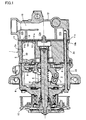
- a variable displacement swash plate compressor 1 comprises a circular-column-shaped cylinder block 2 provided with a plurality of cylinder bores 2a, a front housing 4 given a cylindrical shape closed at one end and opposing one of the end faces of the cylinder block 2 to cooperate with the cylinder block 2 and thereby form a crank chamber 3, a rotation shaft 5 disposed in the crank chamber 3, rotatably supported by the cylinder block 2 and the front housing 4, and extending out of the crank chamber 3 through the front housing 4 at one end, a rotor 6 disposed in the crank chamber 3 and fixed to the rotation shaft 5, a swash plate 8 disposed in the crank chamber 3, connected to the rotor 6 through a link member 7, engaging the rotation shaft 5 at a variable inclination, and rotated by the rotation shaft 5, pairs of shoes 9 disposed in the crank chamber 3 and slidably engaging the outer peripheral portion of the swash plate 8, pistons 10 fitted in the cylinder bores 2a and slidably engaging the outer peripheral portion of
- the rotation shaft 5, the rotor 6, the link member 7, the swash plate 8 and the shoes 9 constitute a piston driving mechanism.
- the cylinder bores 2a, the pistons 10, the suction holes 11a, the discharge holes 11b, the suction valves 13, the discharge valves 14 and pairs of shoes 9 are distanced from each other in the circumferential direction.
- the suction chamber 12a communicates with the evaporator of a car air conditioner through a suction port 16.
- the discharge chamber 12b communicates with the condenser of the car air conditioner through a discharge port.
- the evaporator, the condenser, the car air conditioner and the discharge port are not shown in Figure 1 .
- the rotation shaft 5 is directly connected to a car engine through a power transmission device 17 at one end protruding out of the crank chamber 3.
- the car engine is not shown in Figure 1 .
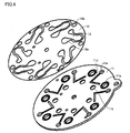
- the suction valves 13 are made by punching U-shaped holes 18a through a circular thin plate 18.
- the circular thin plate 18 is provided with holes 18b for accommodating the through-bolts 15, in addition to the U-shaped holes 18a.
- the valve plate 11 cooperates with the cylinder block 2 to clamp the circular thin plate 18, thereby making the circular thin plate 18 abut on the valve plate 11.
- the suction valves 13 are fitted on the valve plate 11.
- the U-shaped holes 18a oppose the discharge holes 11b formed in the valve plate 11 when the circular thin plate 18 is clamped by the valve plate 11 and the cylinder block 2 to abut on the valve plate 11.
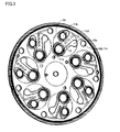
- the valve plate 11 is provided with holes 11c for accommodating the through-bolts 15, in addition to the suction holes 11a and the discharge holes 11b.
- the valve plate 11 is provided with grooves 11d in the end face opposing the cylinder block 2 through the circular thin plate 18.
- the grooves 11d extend from the holes 11c to the portions abutting the suction valves 13 without interfering with the adjacent discharge holes 11b or opposing the U-shaped holes 18a of the circular thin plate 18 abutting the valve plate 11.
- the grooves 11d extend beyond the portions opposing the roots of the suction valves 13 to the portions near the suction holes 11a.
- the grooves 11d communicate with the crank chamber 3 through the holes 11c formed in the valve plate 11 and accommodating the-through bolts, the holes 18b formed in the circular thin plate 18 and accommodating the through-bolts, and holes 2b formed in the cylinder block 2 and accommodating the through-bolts.
- variable displacement swash plate compressor 1 the rotation shaft 5 is rotated by the car engine, the swash plate 8 rotates synchronously with the rotation of the rotation shaft 5, and the pistons 10 reciprocally move. Synchronously with the reciprocal movement of the pistons 10, coolant gas returns to the compressor from the evaporator of the car air conditioner, flows into the cylinder bores 2a through the suction port 16, the suction chamber 12a, the suction holes 11a and the suction valves 13, becomes compressed in the cylinder bores 2a, and flows out of the compressor 1 to the condenser of the car air conditioner through the discharge holes 11b, the discharge valves 14, the discharge chamber 12b and the discharge port.
- crank chamber pressure is applied on the surfaces of the suction valves 13 abutting the valve plate 11 through the holes 2b formed in the cylinder block 2 and accommodating the through-bolts, holes 18b formed in the circular thin plate 18 and accommodating the through-bolts, holes 11c formed in the valve plate 11 and accommodating the through-bolts, and pressure induction passages formed by the grooves 11d formed in the end face of the valve plate 11 opposing the cylinder block 2 and the circular thin plate 18 abutting the valve plate 11.
- the crank chamber pressure applied on the suction valves 13 forces the suction valves 13 in the opening direction.
- the present invention can be widely used in various kinds of reciprocating compressors including swash plate compressors, wobble plate compressors, etc.
Landscapes
- Engineering & Computer Science (AREA)
- Mechanical Engineering (AREA)
- General Engineering & Computer Science (AREA)
- Compressors, Vaccum Pumps And Other Relevant Systems (AREA)
- Compressor (AREA)
Applications Claiming Priority (2)
| Application Number | Priority Date | Filing Date | Title |
|---|---|---|---|
| JP2008087337A JP5065120B2 (ja) | 2008-03-28 | 2008-03-28 | 往復動圧縮機 |
| PCT/JP2009/054650 WO2009119316A1 (ja) | 2008-03-28 | 2009-03-11 | 往復動圧縮機 |
Publications (2)
| Publication Number | Publication Date |
|---|---|
| EP2280171A1 true EP2280171A1 (de) | 2011-02-02 |
| EP2280171A4 EP2280171A4 (de) | 2011-05-25 |
Family
ID=41113514
Family Applications (1)
| Application Number | Title | Priority Date | Filing Date |
|---|---|---|---|
| EP09724940A Withdrawn EP2280171A4 (de) | 2008-03-28 | 2009-03-11 | Hubkolbenverdichter |
Country Status (5)
| Country | Link |
|---|---|
| US (1) | US8684703B2 (de) |
| EP (1) | EP2280171A4 (de) |
| JP (1) | JP5065120B2 (de) |
| CN (1) | CN101970878B (de) |
| WO (1) | WO2009119316A1 (de) |
Cited By (1)
| Publication number | Priority date | Publication date | Assignee | Title |
|---|---|---|---|---|
| EP3023640A1 (de) * | 2014-11-10 | 2016-05-25 | LG Electronics Inc. | Hubkolbenverdichter |
Families Citing this family (7)
| Publication number | Priority date | Publication date | Assignee | Title |
|---|---|---|---|---|
| JP5324893B2 (ja) * | 2008-11-18 | 2013-10-23 | サンデン株式会社 | 圧縮機の弁板装置 |
| JP5559720B2 (ja) * | 2010-03-31 | 2014-07-23 | 株式会社豊田自動織機 | 圧縮機 |
| AT509081B1 (de) * | 2010-04-08 | 2011-06-15 | Hoerbiger Kompressortech Hold | Hohle ventilplatte |
| BRPI1105143B1 (pt) * | 2011-12-15 | 2021-07-27 | Embraco Indústria De Compressores E Soluções Em Refrigeração Ltda | Conjunto de válvulas de sucção para compressor alternativo |
| CN104179656B (zh) * | 2014-08-18 | 2016-09-21 | 合肥达因汽车空调有限公司 | 一种变排量旋转斜盘式压缩机 |
| JP2016070167A (ja) * | 2014-09-30 | 2016-05-09 | 株式会社ヴァレオジャパン | 往復動式圧縮機 |
| CN104533596B (zh) * | 2014-11-15 | 2017-01-18 | 汪培杰 | 流体转移装置用的触发轮的设计方法 |
Family Cites Families (24)
| Publication number | Priority date | Publication date | Assignee | Title |
|---|---|---|---|---|
| US5044892A (en) * | 1990-03-05 | 1991-09-03 | General Motors Corporation | Swash plate compressor lubrication system |
| JP2587085Y2 (ja) | 1992-05-06 | 1998-12-14 | 株式会社豊田自動織機製作所 | ピストン式圧縮機の吸入リード弁機構 |
| JPH0886279A (ja) | 1994-09-16 | 1996-04-02 | Toyota Autom Loom Works Ltd | 往復動型圧縮機 |
| US5795139A (en) | 1995-03-17 | 1998-08-18 | Kabushiki Kaisha Toyoda Jidoshokki Seisakusho | Swash plate type refrigerant compressor with improved internal lubricating system |
| JPH08254183A (ja) * | 1995-03-17 | 1996-10-01 | Toyota Autom Loom Works Ltd | 斜板式圧縮機 |
| US5672053A (en) | 1995-04-03 | 1997-09-30 | General Motors Corporation | Compressor reed valve with valve plate channel |
| JPH10196536A (ja) | 1997-01-13 | 1998-07-31 | Toyota Autom Loom Works Ltd | 往復動型圧縮機におけるシール部材の劣化防止構造 |
| JPH10299656A (ja) * | 1997-04-22 | 1998-11-10 | Zexel Corp | 往復式圧縮機 |
| JPH1162823A (ja) * | 1997-08-08 | 1999-03-05 | Sanden Corp | 可変容量圧縮機 |
| JP2000329066A (ja) * | 1999-05-19 | 2000-11-28 | Toyota Autom Loom Works Ltd | ピストン式圧縮機における吸入弁構造 |
| JP4242990B2 (ja) * | 1999-11-25 | 2009-03-25 | サンデン株式会社 | 斜板式圧縮機 |
| US7004734B2 (en) | 1999-12-28 | 2006-02-28 | Zexel Valco Climate Control Corporation | Reciprocating refrigerant compressor |
| JP2001193649A (ja) * | 1999-12-28 | 2001-07-17 | Zexel Valeo Climate Control Corp | 往復式冷媒圧縮機 |
| FR2809459A1 (fr) * | 2000-05-24 | 2001-11-30 | Sanden Corp | Compresseur a cylindree variable du type a came inclinee avec un mecanisme de commande de capacite |
| JP2003028057A (ja) * | 2001-07-13 | 2003-01-29 | Toyota Industries Corp | 可変容量型圧縮機における絞り構造 |
| US7390176B2 (en) * | 2001-10-05 | 2008-06-24 | Carrier Corporation | Multi-port suction reed valve with optimized tips |
| WO2005033510A1 (en) * | 2003-09-30 | 2005-04-14 | Calsonic Kansei Corporation | Compressor and suction valve structure |
| JP2005105975A (ja) * | 2003-09-30 | 2005-04-21 | Calsonic Kansei Corp | 圧縮機の弁構造 |
| JP2007064196A (ja) | 2005-08-05 | 2007-03-15 | Valeo Thermal Systems Japan Corp | 弁機構構成部材の加工方法 |
| JP4794274B2 (ja) * | 2005-10-27 | 2011-10-19 | カルソニックカンセイ株式会社 | 可変容量圧縮機 |
| JP4737076B2 (ja) * | 2006-05-19 | 2011-07-27 | 株式会社豊田自動織機 | 圧縮機 |
| JP4706617B2 (ja) * | 2006-11-03 | 2011-06-22 | 株式会社豊田自動織機 | 圧縮機の吸入絞り弁 |
| JP4730317B2 (ja) * | 2007-02-02 | 2011-07-20 | 株式会社豊田自動織機 | 両頭ピストン式圧縮機 |
| EP2088318A1 (de) * | 2008-02-05 | 2009-08-12 | Kabushiki Kaisha Toyota Jidoshokki | Taumelscheibenverdichter |
-
2008
- 2008-03-28 JP JP2008087337A patent/JP5065120B2/ja not_active Expired - Fee Related
-
2009
- 2009-03-11 CN CN2009801098502A patent/CN101970878B/zh not_active Expired - Fee Related
- 2009-03-11 US US12/935,245 patent/US8684703B2/en not_active Expired - Fee Related
- 2009-03-11 EP EP09724940A patent/EP2280171A4/de not_active Withdrawn
- 2009-03-11 WO PCT/JP2009/054650 patent/WO2009119316A1/ja not_active Ceased
Cited By (2)
| Publication number | Priority date | Publication date | Assignee | Title |
|---|---|---|---|---|
| EP3023640A1 (de) * | 2014-11-10 | 2016-05-25 | LG Electronics Inc. | Hubkolbenverdichter |
| US10180131B2 (en) | 2014-11-10 | 2019-01-15 | Lg Electronics Inc. | Reciprocating compressor |
Also Published As
| Publication number | Publication date |
|---|---|
| WO2009119316A1 (ja) | 2009-10-01 |
| CN101970878B (zh) | 2013-08-07 |
| CN101970878A (zh) | 2011-02-09 |
| JP2009243276A (ja) | 2009-10-22 |
| EP2280171A4 (de) | 2011-05-25 |
| JP5065120B2 (ja) | 2012-10-31 |
| US20110020158A1 (en) | 2011-01-27 |
| US8684703B2 (en) | 2014-04-01 |
Similar Documents
| Publication | Publication Date | Title |
|---|---|---|
| EP2280171A1 (de) | Hubkolbenverdichter | |
| JP4514232B2 (ja) | 圧縮機 | |
| EP2865893B1 (de) | Ventilanordnung für Taumelscheibenkompressor mit variabler Verdrängung | |
| KR20140104300A (ko) | 흡입체크밸브 | |
| EP1174619A3 (de) | Gehäuse eines Taumelscheibenkompressors | |
| EP2045465A1 (de) | Verdichter | |
| US9157427B2 (en) | Compressor | |
| US6632074B2 (en) | Pressure setting means for a multistage type piston compressor | |
| JP3858814B2 (ja) | 回転機械の調整方法 | |
| KR20150060199A (ko) | 왕복식 압축기 | |
| US8215924B2 (en) | Oil separating structure of variable displacement compressor | |
| EP1947336A1 (de) | Hubkolbenverdichter | |
| US6912948B2 (en) | Swash plate compressor | |
| KR101515643B1 (ko) | 압축기 | |
| KR20080055117A (ko) | 가변용량형 사판식 압축기 | |
| EP3896284A1 (de) | Taumelscheibenverdichter | |
| EP2489877A1 (de) | Verdichter | |
| KR101085723B1 (ko) | 압축기 | |
| KR100532133B1 (ko) | 가변형 사판식 압축기 | |
| JP2002021717A (ja) | 片頭ピストン型圧縮機 | |
| KR20040094155A (ko) | 차량 공조용 사판식 압축기 | |
| KR20110072317A (ko) | 가변용량형 사판식 압축기 | |
| KR20090011465A (ko) | 사판식 압축기용 피스톤 | |
| JP2007278180A (ja) | 往復動圧縮機 | |
| KR20130057726A (ko) | 압축기 |
Legal Events
| Date | Code | Title | Description |
|---|---|---|---|
| PUAI | Public reference made under article 153(3) epc to a published international application that has entered the european phase |
Free format text: ORIGINAL CODE: 0009012 |
|
| 17P | Request for examination filed |
Effective date: 20101020 |
|
| AK | Designated contracting states |
Kind code of ref document: A1 Designated state(s): AT BE BG CH CY CZ DE DK EE ES FI FR GB GR HR HU IE IS IT LI LT LU LV MC MK MT NL NO PL PT RO SE SI SK TR |
|
| AX | Request for extension of the european patent |
Extension state: AL BA RS |
|
| A4 | Supplementary search report drawn up and despatched |
Effective date: 20110427 |
|
| STAA | Information on the status of an ep patent application or granted ep patent |
Free format text: STATUS: THE APPLICATION HAS BEEN WITHDRAWN |
|
| 18W | Application withdrawn |
Effective date: 20110526 |
|
| DAX | Request for extension of the european patent (deleted) |