EP2281159B1 - Porte pour appareil ménager - Google Patents
Porte pour appareil ménager Download PDFInfo
- Publication number
- EP2281159B1 EP2281159B1 EP09738017.4A EP09738017A EP2281159B1 EP 2281159 B1 EP2281159 B1 EP 2281159B1 EP 09738017 A EP09738017 A EP 09738017A EP 2281159 B1 EP2281159 B1 EP 2281159B1
- Authority
- EP
- European Patent Office
- Prior art keywords
- door
- wall
- connection piece
- latching
- section
- Prior art date
- Legal status (The legal status is an assumption and is not a legal conclusion. Google has not performed a legal analysis and makes no representation as to the accuracy of the status listed.)
- Not-in-force
Links
Images



Classifications
-
- F—MECHANICAL ENGINEERING; LIGHTING; HEATING; WEAPONS; BLASTING
- F25—REFRIGERATION OR COOLING; COMBINED HEATING AND REFRIGERATION SYSTEMS; HEAT PUMP SYSTEMS; MANUFACTURE OR STORAGE OF ICE; LIQUEFACTION SOLIDIFICATION OF GASES
- F25D—REFRIGERATORS; COLD ROOMS; ICE-BOXES; COOLING OR FREEZING APPARATUS NOT OTHERWISE PROVIDED FOR
- F25D23/00—General constructional features
- F25D23/02—Doors; Covers
- F25D23/028—Details
-
- E—FIXED CONSTRUCTIONS
- E05—LOCKS; KEYS; WINDOW OR DOOR FITTINGS; SAFES
- E05D—HINGES OR SUSPENSION DEVICES FOR DOORS, WINDOWS OR WINGS
- E05D11/00—Additional features or accessories of hinges
- E05D11/0081—Additional features or accessories of hinges for transmitting energy, e.g. electrical cable routing
-
- E—FIXED CONSTRUCTIONS
- E05—LOCKS; KEYS; WINDOW OR DOOR FITTINGS; SAFES
- E05D—HINGES OR SUSPENSION DEVICES FOR DOORS, WINDOWS OR WINGS
- E05D7/00—Hinges or pivots of special construction
- E05D7/08—Hinges or pivots of special construction for use in suspensions comprising two spigots placed at opposite edges of the wing, especially at the top and the bottom, e.g. trunnions
- E05D7/081—Hinges or pivots of special construction for use in suspensions comprising two spigots placed at opposite edges of the wing, especially at the top and the bottom, e.g. trunnions the pivot axis of the wing being situated near one edge of the wing, especially at the top and bottom, e.g. trunnions
-
- E—FIXED CONSTRUCTIONS
- E05—LOCKS; KEYS; WINDOW OR DOOR FITTINGS; SAFES
- E05Y—INDEXING SCHEME ASSOCIATED WITH SUBCLASSES E05D AND E05F, RELATING TO CONSTRUCTION ELEMENTS, ELECTRIC CONTROL, POWER SUPPLY, POWER SIGNAL OR TRANSMISSION, USER INTERFACES, MOUNTING OR COUPLING, DETAILS, ACCESSORIES, AUXILIARY OPERATIONS NOT OTHERWISE PROVIDED FOR, APPLICATION THEREOF
- E05Y2900/00—Application of doors, windows, wings or fittings thereof
- E05Y2900/30—Application of doors, windows, wings or fittings thereof for domestic appliances
- E05Y2900/31—Application of doors, windows, wings or fittings thereof for domestic appliances for refrigerators
-
- F—MECHANICAL ENGINEERING; LIGHTING; HEATING; WEAPONS; BLASTING
- F25—REFRIGERATION OR COOLING; COMBINED HEATING AND REFRIGERATION SYSTEMS; HEAT PUMP SYSTEMS; MANUFACTURE OR STORAGE OF ICE; LIQUEFACTION SOLIDIFICATION OF GASES
- F25D—REFRIGERATORS; COLD ROOMS; ICE-BOXES; COOLING OR FREEZING APPARATUS NOT OTHERWISE PROVIDED FOR
- F25D2400/00—General features of, or devices for refrigerators, cold rooms, ice-boxes, or for cooling or freezing apparatus not covered by any other subclass
- F25D2400/18—Aesthetic features
Definitions
- the invention relates to a door for a household appliance with an outer wall, an inner wall, between which a cavity is arranged, and with a connecting piece arranged between the outer and inner wall.
- the invention is also directed to a household appliance which is equipped with a corresponding door, in particular a refrigerator or freezer.
- refrigeration appliances such as refrigerators or freezers
- a double-walled door with an outer and inner wall, between which a cavity filled with insulating foam material is formed.
- the outer wall is often formed by a door panel, which is bent on the sides towards the inner wall.
- the cavity and / or the cavity is often closed by a connecting piece or a door end strip, which e.g. is designed as a plastic injection molded part.
- the DE 20 2005 014 382 U1 discloses a generic door for a refrigerator with an outer wall and an inner wall which laterally surround a cavity, and at least one so-called closing part which closes an upper and lower opening of the cavity delimited by the outer wall and inner wall.
- the end part has a base plate and a web extending along an edge of the base plate.
- the outer wall has a cranked edge region, which bears against an inner side of the web, so that the web is flush with the outer wall.
- JP 04 000176 A discloses a refrigerator door in which a cover element is fastened to a door end strip by means of latching hooks, the door end strip being screwed to the refrigerator door.
- a door for a household appliance which has an outer wall and an inner wall, the walls being connected to a connecting piece.
- the connecting piece can have at least one mechanical coupling element, which can couple to a coupling edge by means of teeth formed in a coupling element.
- a connecting piece can also have an area in which a pivoting element of a pivoting device of the household appliance can engage in order to enable a pivotable mounting of the door on the housing of the household appliance.
- Household appliances are also known in which the outer wall is higher than the inner wall, so that the end part is at least partially covered by the outer wall on the visible side of the door.
- the object of the invention is therefore to provide a door for a household appliance in which a connecting piece, which is arranged between the outside and inside, can be attached to the door in a particularly simple manner.
- a door according to claim 1 in which the connecting piece is fastened to the outer wall by a positive connection.
- This positive connection is preferably distinguished by the fact that it is not visible from the outside, neither from the visible side of the door nor from the inside of the door.
- the positive connection is e.g. formed on a side of the connecting piece facing the cavity.
- the connecting piece connects the outer and inner wall to one another. It particularly preferably closes off the cavity between the outer and inner walls of the door on one side.
- the connector can also be referred to as a door trim strip.
- the connecting piece is preferably at least partially covered by the outer wall towards a visible side of the door.
- the invention is thus used particularly advantageously in doors in which the outer wall is somewhat longer, in particular higher, than the inner wall.
- the connecting piece then closes the cavity between the outer and inner walls and, when viewed from the visible side, lies behind the outer wall. This leads to a uniform outside of the door.
- the outer wall is preferably formed by a door panel, which e.g. is made of a sheet metal.
- the inner wall is preferably made of plastic, as is the connecting piece.
- the connecting piece is particularly preferably designed as a plastic injection molded part.
- the positive connection is a snap-in connection.
- one of the connecting piece and the outer wall has at least one latching hook and the other has at least one latching surface or Locking edge.
- the latching hook engages behind the latching surface or latching edge and thereby establishes a latching connection.
- the connector can also be a combination of a positive locking connection and a non-positive, e.g. frictional, connection, or by combinations of a positive locking connection and a material connection to the outer wall.
- the latching hook or the latching surface or latching edge are preferably formed in one piece with the connecting piece. This eliminates the use of additional parts to attach the connector to the outer wall.
- the latching hook is preferably arranged elastically resiliently on the connecting piece or on the outer wall.
- the resilient movement preferably runs at least partially parallel to the locking surface or locking edge on the other part, so that the locking hook can slide resiliently behind it when the connecting piece is being fitted.
- the latching surface or latching edge is elastically resilient, preferably again in one direction at least partially parallel to the latching surface. In particular in connection with a resilient locking hook, this allows the connector to be easily installed.
- the outer wall is bent at least on one side to form an outer wall side section toward the inner wall, the connecting piece being fastened in a form-fitting manner to the at least one outer wall side section.
- the outer wall side section then preferably at least partially covers the short sides of the connecting piece.
- the outer wall is particularly preferably bent symmetrically inwards on both sides in order to create a symmetrical door which can be hinged to the left and right of a body of the household appliance.
- the outer wall is preferably bent toward the inner wall with a relatively large radius of curvature.
- a latching hook formed on the connecting piece particularly preferably engages behind a latching edge formed on the outer wall side section.
- This locking edge preferably extends over a substantial part of the length of the outer wall and is preferably formed by a first bent section which is bent inwards from the outer wall side section.
- the first bent section is preferably approximately parallel to the outer wall side section and approximately transverse to the visible side the door.
- the latching edge is preferably formed by an edge of the bent section which faces the visible side of the door.
- the latching hook is preferably arranged on a rib of the connecting piece.
- the rib is preferably sufficiently thin to ensure a resilient suspension of the locking hook. In particular, it is arranged transversely to the latching edge or latching surface on the outer door.
- the rib advantageously projects downward from a base plate of the connecting piece and is arranged approximately parallel to the outer wall side section, but transversely to the visible side.
- the rib is preferably attached to the connecting piece only on one side in order to be pivotable in a resilient manner.
- the locking lug can also be arranged on the outer wall, and can engage behind a locking edge on the connecting piece.
- the latch on the outer wall can e.g. be formed by an angled portion of the outer wall. For this, e.g. a section punched out of the outer wall side section and bent out of the surface of the side section.
- the locking surface or locking surface on the connector can then e.g. be formed by a recess in the connector or in a wall of the connector.
- the outer wall on an end face of the door is preferably folded inwards towards a second bent section, the second bent section being received in a groove formed on the connecting piece.
- a tongue and groove connection is created, which fixes the connection piece in one direction on the outer wall, e.g. in such a way that it cannot slip up and down.
- the second chamfer section is preferably chamfered from the upper end face of the outer wall.
- the groove is particularly preferably located below an upper side of the connecting piece, so that this forms the upper end of the door.
- the connecting piece is particularly preferably fastened to the outer wall with two of the snap-in connections described above. These are preferably located near the two short sides of the connector.
- the connecting piece has a receiving space which is designed to receive a hinge element.
- a locking hook of the connecting piece is arranged below the receiving space.
- the latching hook can be arranged on a rib which projects downwards from the bottom wall of the receiving space.
- the invention is also directed to a household appliance which is equipped with a door according to the invention.
- the household appliance is preferably a refrigerator or freezer.
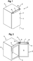
- Fig. 1 shows as an embodiment of a household appliance, in which the invention is implemented, a refrigerator 1 in a stand-alone construction with a body 4 and a door 2 which is pivoted on the body 4 about an axis 3.
- the axis 3 runs through the door 2 parallel to one in Fig. 1 Side surface of the body 4 facing away from the viewer.
- the door 2 comprises an outer wall 5 which is bent inwards on the sides and is advantageously formed from sheet metal, in particular sheet metal.
- the resulting cavity in the door is limited to the inside of the refrigerator by the inner wall 6, see Fig. 2 , which is advantageously molded from plastic.
- the cavity formed between the outer wall 5 and the inner wall 6 is filled with insulating foam material.
- the outer and inner walls are connected to one another at the upper end of the door by a connecting piece 7, which at the same time closes off the cavity in the door.
- the connecting piece 7 essentially has an elongated cuboid shape, the length of which corresponds approximately to the width of the door.
- the height and depth of the connector 7 correspond approximately to the thickness of the door and are each a few cm.
- the cavity is also delimited at the bottom by a lower connecting piece (not shown). This can be of the same or different design as the upper connecting piece 7.
- receiving spaces 8 are provided on both sides. In order to cover the receiving spaces 8 upwards, one is on the connector 7 in the 1 and 2 Cover strip, not shown, placed.
- the door is preferably mirror-symmetrical about a longitudinal axis, so that it can be articulated on both sides of the body.
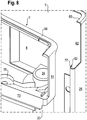
- Fig. 2 shows the refrigerator of the Fig. 1 with the door open.
- both receiving spaces 8 can be clearly recognized.
- the support arm of a hinge element 10 which is fastened to the upper section 9 of the front frame of the body 4 facing the door 2, projects into the receiving space 8 arranged there.
- display and / or control elements for the refrigerator are also arranged on the upper section 9.
- the outer wall 5 is longer in the direction of the pivot axis 3 than the inner wall 6, so that the connecting piece 7 is completely or partially covered by the outer wall 5 on the visible side.
- the door 2 has a uniform outer surface formed by the outer wall 5, which creates an attractive aesthetic impression.
- Fig. 3 shows a perspective view of a top right corner of the body 2, on which the in Fig. 2 recognizable hinge element 10 is attached.
- the hinge element 10 is formed from an upright oriented strip of heavy plate and has a mounting section 11 for attachment to the body 4 of the household appliance 1 and a support arm 12 projecting from the mounting section 11, at the end of which two identical bearing pins 16a and 16b projecting upwards and downwards. covered) are arranged.
- two bores 17 can be seen, which are provided to receive screws (not shown) with which the hinge element 10 is fastened to the body 4 of the household appliance 1.
- a bearing pin 20 can also be seen, which is placed on the lower bearing pin 16b.
- a cross section of the bearing pin 20 along the line VII is in Fig. 4 shown.
- the bearing pin 20 has a lower section with a circular cylindrical outer surface, which is provided for storage in a bearing eye fixed to the door.
- a shell-like section 19 protrudes upward on one side and serves as a cable duct and as a cladding for the end section of the hinge element 10.
- a hole 22 with a square cross section is provided in the bearing pin 20, which receives the bearing journal 16b without play.
- Adjacent to the hole 22 is a cable duct 21 running parallel to the pivot axis with an oval or any Arranged cross section, which is provided for guiding cables from the body 4 into the door 2.
- the cable duct 21 and the hole 22 are preferably continuous.
- Fig. 5 shows a perspective view into the receiving space 8 in the upper right corner of the door 2, seen from the body 4.
- the upper section including the cover strip of door 2, has been cut off for better visibility.
- the inner wall 6 can be seen, on the outer edges of which a magnetic seal 29 is arranged.
- the connector 7 connects above the inner wall 6.
- the outer wall 5 Arranged behind this is the outer wall 5, which is bent to the side toward an outer wall side section 25. Together with a side wall section 51 of the connecting piece 7, the outer wall side section 25 thus forms the side wall 28 of the receiving space 8 in the door 2.
- the receiving space 8 also has a bottom wall 37 and a wall 38 to the visible side of the door, in which a pocket 39 is inserted.
- the wall 39 runs parallel to and very close to or adjoining the outer wall 5.
- the bearing eye 24 is further formed by forming a bearing sleeve 23 in which the bearing pin 20 (in Fig. 5 not shown) is included.
- an opening limiting body 30 which is formed by a wire element which has a first end section 32 running approximately parallel to the pivot axis. This end section 32 engages behind the support arm 12 and thereby defines an opening-limited position of the door.
- the second end section 34 of the opening limiting body 30 is curved into an eyelet and received in a depression 35 in the bottom 37 of the connecting piece 7. As a result, it is positively attached to the door.
- the second end section 34 is additionally fastened in the middle of the eyelet by a screw 31.
- the middle section 33 of the opening-limiting body 30 runs along a bearing surface 36 which is oriented obliquely with respect to the pivot axis 3 and which is also formed in the bottom 37 of the connecting piece 7.
- Fig. 6 shows how Fig. 3 a perspective view of the upper right corner of the refrigerator 1, with the door hinged.
- the lower portion of the bearing pin 20 is pivotally received in the bearing sleeve 23 of the bearing eye 24.
- the first end portion 32 of the opening limiting body 30 engages behind the support arm 12 and is therefore in FIG Fig. 6 covered.
- the receiving space 8 is covered at the top by a cover strip 43.
- a cable bundle 45 which is guided through the cable channel 21 in the bearing pin 20 into the cavity of the door 2.
- Fig. 7 the underside of the connecting piece 7 can now also be seen.
- This has a wall section 73 facing the body and two walls 74, 75 serving for stability.
- the bottom wall 37 of the receiving space 8 is covered by these walls 74, 75.
- the bearing sleeve 23 extends from the bearing eye 24 down into the cavity so that cables can be guided from the body into the door.
- a rib 71 projects downward, on which a locking lug 70 is formed.
- the latching nose with its latching surface 80 engages behind an edge of the first bent section 77 of the outer wall 5, which in FIG Fig. 7 covered, however in Fig. 8 is recognizable.
- the outer wall 5 on the left side of the door is bent over to an outer wall side section 25 which is approximately perpendicular to the visible surface or front side of the door which is formed by the outer wall 5.
- the outer wall side section 25 is in turn angled to a first bent section 77. At its edge, this runs approximately parallel to the outer wall side section 25, so that its edge 82 faces the visible surface of the door.
- the latching hook 70 engages with its latching surface 80 behind the latching edge 82 of the first bent section 77 and thus creates a positive connection.
- the side wall section 51 of the receiving space 8 slides into the area 62 in which a recess is formed in the outer wall 5.
- the side wall section 51 slightly overlaps the outer wall side section 25 to create a continuous outer surface.
- the inner wall 6 (not shown) adjoins the door.
- the latching lug 70 can also be moved up and down after it has snapped into place. So that the connecting piece is also fixed in this direction on the outer door in this direction after the locking edge 82, a groove 76 is formed on an upper end flange 59, the so-called dome, of the connecting piece 7, which is shown in the longitudinal sectional drawing in FIG Fig. 9 is recognizable. A second bevel section 63 is inserted into the groove 76 on the upper end face of the outer wall 5, so that a tongue and groove connection is created. From the visible side of the door, in the Fig. 9 seen from the right, the connector 7 is thus practically completely covered by the outer wall 5.
- Fig. 10 shows the locking connection between the connector 7 and the outer wall 5 again in cross section at a height below the locking hook 70, seen from below.
- the bearing sleeve 23, through which the end flange 59 is visible, is first clearly visible. To the outside, the visible side of the door is delimited by the outer wall 5, which practically completely covers the connecting piece 7 to the outside.
- the walls 74, 75 are in the Fig. 8 cut while the bottom wall 37 as well as the wall 73 is seen from below.
- An outer wall side section 25 is angled from the outer wall 5, which runs approximately parallel and flush to a side wall of the body 4 and is bent at its end facing the body 4 to form the first bent section 7.
- the radius of curvature of this bend is approx. 0.5 - 4 mm.
- the first bent section 77 is approximately parallel to the outer wall side section 25, but it could also be arranged at an angle to this.
- the latching hook 70 is latched behind the first bent section 77, the latching surface 80 of which engages behind the latching edge 82 of the bent section 77.
- the latching hook is arranged on a resilient rib 71.
- the connector 7 When the connector 7 is assembled, it is pressed against the outer wall 5 along the arrow P.
- the assembly is simplified in that both the outer wall 5 and the outer wall side section 25 spring slightly outwards, and in addition the rib 71 springs slightly inwards. This allows the latch 70, if that Connector 7 is moved in the direction of arrow P, slide slightly behind the bent portion 77.
Landscapes
- Engineering & Computer Science (AREA)
- Chemical & Material Sciences (AREA)
- Combustion & Propulsion (AREA)
- Physics & Mathematics (AREA)
- Mechanical Engineering (AREA)
- Thermal Sciences (AREA)
- General Engineering & Computer Science (AREA)
- Refrigerator Housings (AREA)
Claims (16)
- Porte (2) pour un appareil ménager (1) comprenant une paroi extérieure (5), une paroi intérieure (6), entre lesquelles un espace creux est ménagé, et comprenant une pièce de jonction (7) disposée entre la paroi extérieure et la paroi intérieure (6), qui relie la paroi extérieure (5) et la paroi intérieure (6) et qui est fixée par un assemblage par ajustement de forme à la paroi extérieure (5), dans laquelle, parmi la pièce de jonction (7) et la paroi extérieure (5), l'une des deux comprend au moins un crochet d'encliquetage (70) et l'autre comprend une surface d'encliquetage ou un bord d'arrêt (82), et la pièce de jonction (7) comprend un espace de réception (8) configuré pour recevoir un élément de charnière (10),
caractérisée en ce que le crochet d'encliquetage (70) de la pièce de jonction (7) est disposé en dessous de l'espace de réception (8). - Porte (2) selon la revendication 1, caractérisée en ce que le crochet d'encliquetage (70) resp. la surface d'encliquetage ou le bord d'arrêt sont formés d'une seule pièce avec la pièce de jonction (7).
- Porte (2) selon la revendication 1 ou 2, caractérisée en ce que le crochet d'encliquetage (70) fait ressort de façon élastique.
- Porte (2) selon la revendication 1, 2 ou 3, caractérisée en ce que la surface d'encliquetage ou le bord d'arrêt (82) fait ressort de façon élastique.
- Porte (2) selon l'une des revendications précédentes, caractérisée en ce que la paroi extérieure (5) est recourbée au moins sur un côté jusqu'à la paroi intérieure (6) pour former une partie latérale de paroi extérieure (25), dans laquelle la pièce de jonction (7) est fixée par ajustement de forme à la au moins une partie latérale de paroi extérieure (25).
- Porte (2) selon l'une des revendications précédentes, caractérisée en ce qu'un crochet d'encliquetage (70) formé sur la pièce de jonction (7) vient en prise par l'arrière avec le bord d'arrêt (82) formé sur la partie latérale de la paroi extérieure (25).
- Porte (2) selon l'une des revendications précédentes, caractérisée en ce qu'une partie d'extrémité de la partie latérale de paroi extérieure (25) est repliée vers l'intérieur pour former une première partie de pliure (77), dans laquelle le bord d'arrêt (82) de la paroi extérieure (5) est formé par un bord de la partie de pliure (77).
- Porte (2) selon l'une des revendications précédentes, caractérisée en ce que le crochet d'encliquetage (70) est disposé sur une nervure (71) de la pièce de jonction (7).
- Porte (2) selon la revendication 8, caractérisée en ce que la nervure (71) est parallèle à une face frontale de la porte (2).
- Porte (2) selon l'une des revendications 1 à 7, caractérisée en ce que la paroi extérieure (5) comprend un ergot d'encliquetage qui vient en prise par derrière avec un bord d'arrêt sur la pièce de jonction (7).
- Porte (2) selon la revendication 10, caractérisée en ce que l'ergot d'encliquetage est formé par une partie coudée de la paroi extérieure (5) et le bord d'arrêt est formé par un évidement dans la pièce de jonction (7).
- Porte (2) selon l'une des revendications précédentes, caractérisée en ce que la pièce de jonction (7) ferme l'espace creux entre la paroi extérieure et la paroi intérieure jusqu'à un côté avant.
- Porte (2) selon l'une des revendications précédentes, caractérisée en ce que la pièce de jonction (7) est fixée à la paroi extérieure (5) par deux liaisons à encliquetage.
- Porte (2) selon l'une des revendications précédentes, caractérisée en ce que la paroi extérieure (5) est fabriquée en une tôle métallique.
- Porte (2) selon l'une des revendications précédentes, caractérisée en ce que la pièce de jonction (7) est fabriquée en matière plastique.
- Appareil ménager (1), en particulier appareil frigorifique, équipé d'une porte (2) selon l'une des revendications précédentes.
Applications Claiming Priority (2)
| Application Number | Priority Date | Filing Date | Title |
|---|---|---|---|
| DE102008021345A DE102008021345A1 (de) | 2008-04-29 | 2008-04-29 | Tür für ein Haushaltsgerät |
| PCT/EP2009/054617 WO2009132973A1 (fr) | 2008-04-29 | 2009-04-17 | Porte pour appareil ménager |
Publications (2)
| Publication Number | Publication Date |
|---|---|
| EP2281159A1 EP2281159A1 (fr) | 2011-02-09 |
| EP2281159B1 true EP2281159B1 (fr) | 2020-07-29 |
Family
ID=40791079
Family Applications (1)
| Application Number | Title | Priority Date | Filing Date |
|---|---|---|---|
| EP09738017.4A Not-in-force EP2281159B1 (fr) | 2008-04-29 | 2009-04-17 | Porte pour appareil ménager |
Country Status (5)
| Country | Link |
|---|---|
| EP (1) | EP2281159B1 (fr) |
| CN (1) | CN102016465A (fr) |
| DE (1) | DE102008021345A1 (fr) |
| RU (1) | RU2010147317A (fr) |
| WO (1) | WO2009132973A1 (fr) |
Families Citing this family (3)
| Publication number | Priority date | Publication date | Assignee | Title |
|---|---|---|---|---|
| JP7033284B2 (ja) | 2018-09-07 | 2022-03-10 | Smc株式会社 | ワイヤレスバルブマニホールド |
| US11162285B2 (en) | 2019-04-30 | 2021-11-02 | Lovevery, Inc. | Door hinge |
| DE102020212291A1 (de) | 2020-09-29 | 2022-03-31 | BSH Hausgeräte GmbH | Tür für ein Haushaltskältegerät mit spezifischer Kopplung zwischen einer Außenwand und einer Endleiste, sowie Haushaltskältegerät |
Citations (1)
| Publication number | Priority date | Publication date | Assignee | Title |
|---|---|---|---|---|
| US20060265960A1 (en) * | 2005-05-27 | 2006-11-30 | Maytag Corporation | Refrigerator door with end cap |
Family Cites Families (7)
| Publication number | Priority date | Publication date | Assignee | Title |
|---|---|---|---|---|
| JPH0730993B2 (ja) * | 1989-09-28 | 1995-04-10 | 三菱電機株式会社 | 冷蔵庫の扉 |
| JP2731290B2 (ja) * | 1990-11-26 | 1998-03-25 | 株式会社東芝 | 飾り部材付き冷蔵庫扉 |
| JPH07218106A (ja) * | 1994-02-01 | 1995-08-18 | Hitachi Ltd | 冷蔵庫の扉 |
| JP2003166779A (ja) * | 2001-11-29 | 2003-06-13 | Mitsubishi Electric Corp | 冷蔵庫のドア構造 |
| FI6003U1 (fi) * | 2003-05-28 | 2003-11-18 | Helkama Forste Oy | Pintarakenne kodinkoneita ja kylmäkalusteita varten |
| DE202005014382U1 (de) | 2005-09-12 | 2005-11-10 | BSH Bosch und Siemens Hausgeräte GmbH | Tür für ein Kältegerät |
| DE202007007321U1 (de) * | 2007-05-23 | 2007-07-26 | BSH Bosch und Siemens Hausgeräte GmbH | Haushaltsgerät |
-
2008
- 2008-04-29 DE DE102008021345A patent/DE102008021345A1/de not_active Withdrawn
-
2009
- 2009-04-17 RU RU2010147317/13A patent/RU2010147317A/ru not_active Application Discontinuation
- 2009-04-17 EP EP09738017.4A patent/EP2281159B1/fr not_active Not-in-force
- 2009-04-17 WO PCT/EP2009/054617 patent/WO2009132973A1/fr not_active Ceased
- 2009-04-17 CN CN2009801153938A patent/CN102016465A/zh active Pending
Patent Citations (1)
| Publication number | Priority date | Publication date | Assignee | Title |
|---|---|---|---|---|
| US20060265960A1 (en) * | 2005-05-27 | 2006-11-30 | Maytag Corporation | Refrigerator door with end cap |
Also Published As
| Publication number | Publication date |
|---|---|
| DE102008021345A1 (de) | 2009-11-05 |
| RU2010147317A (ru) | 2012-06-10 |
| CN102016465A (zh) | 2011-04-13 |
| EP2281159A1 (fr) | 2011-02-09 |
| WO2009132973A1 (fr) | 2009-11-05 |
Similar Documents
| Publication | Publication Date | Title |
|---|---|---|
| EP2153147B1 (fr) | Appareil ménager | |
| EP2153148B1 (fr) | Appareil ménager | |
| EP2059748B1 (fr) | Appareil frigorifique intégré comportant un dispositif de distribution | |
| EP2274561B1 (fr) | Appareil ménager | |
| EP3467414B1 (fr) | Porte pour un appareil électroménager frigorifique pourvue d'un même dispositif permettant le montage dans les rainures latérales des côtés longitudinaux opposés ainsi que dispositif électroménager frigorifique et procédé de fabrication d'une porte | |
| DE69923885T2 (de) | Schnellkupplung enthaltende Schubladenführung und Schublade | |
| EP3441704A1 (fr) | Porte d'un appareil frigorifique ménager dotée d'une plaque de recouvrement spécifiquement fixée et appareil frigorifique ménager | |
| EP3096098A1 (fr) | Appareil menager frigorifique comprenant une partie de stockage cote porte presentant un axe de pivotement et un axe de pivotement dispose a l'exterieur de la poignee laterale encastree | |
| EP2010031B1 (fr) | Porte pour un appareil frigorifique | |
| DE4418238A1 (de) | Mehrgelenkiges Scharnier | |
| WO2009132946A1 (fr) | Élément de charnière et habillage d'appareil électroménager | |
| CH712724A2 (de) | Kühlerjalousie. | |
| EP1926953B1 (fr) | Porte pour un appareil électroménager | |
| EP2281159A1 (fr) | Porte pour appareil ménager | |
| EP3379180B1 (fr) | Appareil électroménager pourvu d'un corps, d'un élément de fermeture ainsi que d'un conduit fixée sur le corps et sur l'élément de fermeture | |
| DE102011007410A1 (de) | Einbau-Kältegrät mit einem Beschlagsbauteil | |
| EP2107325A1 (fr) | Châssis pour un appareil ménager | |
| DE102017204821A1 (de) | Haushaltsgerätevorrichtung mit einem Korpus, einem Verschlusselement sowie einer an dem Korpus und an dem Verschlusselement befestigten Leitung | |
| DE3804176A1 (de) | Tuerverschluss fuer hausgeraete o. dgl. | |
| EP2283195A1 (fr) | Élément charnière et habillage d'appareil électroménager | |
| EP3537077B1 (fr) | Compartiment de stockage pour produits à réfrigérer pourvu d'un cadre en l, porte ainsi qu'appareil de refroidissement électroménager | |
| EP2023063A2 (fr) | Elément de fermeture de bord de porte d'une porte d'appareil ménager | |
| DE102019216193A1 (de) | Haushaltsgerät mit einem Scharnier und Scharnier für ein Haushaltsgerät | |
| DE4304483A1 (de) | Scharnierverbindung zum beweglichen Verbinden von Bauteilen | |
| DE102022213173A1 (de) | Haushaltskältegerät mit einer Sicherung für einen Griff einer Klappe, sowie Verfahren zum Betätigen einer Klappe |
Legal Events
| Date | Code | Title | Description |
|---|---|---|---|
| PUAI | Public reference made under article 153(3) epc to a published international application that has entered the european phase |
Free format text: ORIGINAL CODE: 0009012 |
|
| 17P | Request for examination filed |
Effective date: 20101129 |
|
| AK | Designated contracting states |
Kind code of ref document: A1 Designated state(s): AT BE BG CH CY CZ DE DK EE ES FI FR GB GR HR HU IE IS IT LI LT LU LV MC MK MT NL NO PL PT RO SE SI SK TR |
|
| AX | Request for extension of the european patent |
Extension state: AL BA RS |
|
| DAX | Request for extension of the european patent (deleted) | ||
| RAP1 | Party data changed (applicant data changed or rights of an application transferred) |
Owner name: BSH HAUSGERAETE GMBH |
|
| STAA | Information on the status of an ep patent application or granted ep patent |
Free format text: STATUS: EXAMINATION IS IN PROGRESS |
|
| 17Q | First examination report despatched |
Effective date: 20170403 |
|
| GRAP | Despatch of communication of intention to grant a patent |
Free format text: ORIGINAL CODE: EPIDOSNIGR1 |
|
| STAA | Information on the status of an ep patent application or granted ep patent |
Free format text: STATUS: GRANT OF PATENT IS INTENDED |
|
| RIC1 | Information provided on ipc code assigned before grant |
Ipc: E05D 7/081 20060101ALN20200210BHEP Ipc: F25D 23/02 20060101AFI20200210BHEP Ipc: E05D 11/00 20060101ALN20200210BHEP |
|
| RIC1 | Information provided on ipc code assigned before grant |
Ipc: E05D 11/00 20060101ALN20200220BHEP Ipc: F25D 23/02 20060101AFI20200220BHEP Ipc: E05D 7/081 20060101ALN20200220BHEP |
|
| INTG | Intention to grant announced |
Effective date: 20200303 |
|
| GRAS | Grant fee paid |
Free format text: ORIGINAL CODE: EPIDOSNIGR3 |
|
| GRAA | (expected) grant |
Free format text: ORIGINAL CODE: 0009210 |
|
| STAA | Information on the status of an ep patent application or granted ep patent |
Free format text: STATUS: THE PATENT HAS BEEN GRANTED |
|
| AK | Designated contracting states |
Kind code of ref document: B1 Designated state(s): AT BE BG CH CY CZ DE DK EE ES FI FR GB GR HR HU IE IS IT LI LT LU LV MC MK MT NL NO PL PT RO SE SI SK TR |
|
| REG | Reference to a national code |
Ref country code: GB Ref legal event code: FG4D Free format text: NOT ENGLISH |
|
| REG | Reference to a national code |
Ref country code: CH Ref legal event code: EP |
|
| REG | Reference to a national code |
Ref country code: DE Ref legal event code: R096 Ref document number: 502009016248 Country of ref document: DE |
|
| REG | Reference to a national code |
Ref country code: AT Ref legal event code: REF Ref document number: 1296279 Country of ref document: AT Kind code of ref document: T Effective date: 20200815 |
|
| REG | Reference to a national code |
Ref country code: IE Ref legal event code: FG4D Free format text: LANGUAGE OF EP DOCUMENT: GERMAN |
|
| REG | Reference to a national code |
Ref country code: LT Ref legal event code: MG4D |
|
| REG | Reference to a national code |
Ref country code: NL Ref legal event code: MP Effective date: 20200729 |
|
| PG25 | Lapsed in a contracting state [announced via postgrant information from national office to epo] |
Ref country code: PT Free format text: LAPSE BECAUSE OF FAILURE TO SUBMIT A TRANSLATION OF THE DESCRIPTION OR TO PAY THE FEE WITHIN THE PRESCRIBED TIME-LIMIT Effective date: 20201130 Ref country code: FI Free format text: LAPSE BECAUSE OF FAILURE TO SUBMIT A TRANSLATION OF THE DESCRIPTION OR TO PAY THE FEE WITHIN THE PRESCRIBED TIME-LIMIT Effective date: 20200729 Ref country code: NO Free format text: LAPSE BECAUSE OF FAILURE TO SUBMIT A TRANSLATION OF THE DESCRIPTION OR TO PAY THE FEE WITHIN THE PRESCRIBED TIME-LIMIT Effective date: 20201029 Ref country code: LT Free format text: LAPSE BECAUSE OF FAILURE TO SUBMIT A TRANSLATION OF THE DESCRIPTION OR TO PAY THE FEE WITHIN THE PRESCRIBED TIME-LIMIT Effective date: 20200729 Ref country code: BG Free format text: LAPSE BECAUSE OF FAILURE TO SUBMIT A TRANSLATION OF THE DESCRIPTION OR TO PAY THE FEE WITHIN THE PRESCRIBED TIME-LIMIT Effective date: 20201029 Ref country code: SE Free format text: LAPSE BECAUSE OF FAILURE TO SUBMIT A TRANSLATION OF THE DESCRIPTION OR TO PAY THE FEE WITHIN THE PRESCRIBED TIME-LIMIT Effective date: 20200729 Ref country code: GR Free format text: LAPSE BECAUSE OF FAILURE TO SUBMIT A TRANSLATION OF THE DESCRIPTION OR TO PAY THE FEE WITHIN THE PRESCRIBED TIME-LIMIT Effective date: 20201030 Ref country code: ES Free format text: LAPSE BECAUSE OF FAILURE TO SUBMIT A TRANSLATION OF THE DESCRIPTION OR TO PAY THE FEE WITHIN THE PRESCRIBED TIME-LIMIT Effective date: 20200729 Ref country code: HR Free format text: LAPSE BECAUSE OF FAILURE TO SUBMIT A TRANSLATION OF THE DESCRIPTION OR TO PAY THE FEE WITHIN THE PRESCRIBED TIME-LIMIT Effective date: 20200729 |
|
| PG25 | Lapsed in a contracting state [announced via postgrant information from national office to epo] |
Ref country code: LV Free format text: LAPSE BECAUSE OF FAILURE TO SUBMIT A TRANSLATION OF THE DESCRIPTION OR TO PAY THE FEE WITHIN THE PRESCRIBED TIME-LIMIT Effective date: 20200729 Ref country code: PL Free format text: LAPSE BECAUSE OF FAILURE TO SUBMIT A TRANSLATION OF THE DESCRIPTION OR TO PAY THE FEE WITHIN THE PRESCRIBED TIME-LIMIT Effective date: 20200729 Ref country code: IS Free format text: LAPSE BECAUSE OF FAILURE TO SUBMIT A TRANSLATION OF THE DESCRIPTION OR TO PAY THE FEE WITHIN THE PRESCRIBED TIME-LIMIT Effective date: 20201129 |
|
| PG25 | Lapsed in a contracting state [announced via postgrant information from national office to epo] |
Ref country code: NL Free format text: LAPSE BECAUSE OF FAILURE TO SUBMIT A TRANSLATION OF THE DESCRIPTION OR TO PAY THE FEE WITHIN THE PRESCRIBED TIME-LIMIT Effective date: 20200729 |
|
| PG25 | Lapsed in a contracting state [announced via postgrant information from national office to epo] |
Ref country code: RO Free format text: LAPSE BECAUSE OF FAILURE TO SUBMIT A TRANSLATION OF THE DESCRIPTION OR TO PAY THE FEE WITHIN THE PRESCRIBED TIME-LIMIT Effective date: 20200729 Ref country code: IT Free format text: LAPSE BECAUSE OF FAILURE TO SUBMIT A TRANSLATION OF THE DESCRIPTION OR TO PAY THE FEE WITHIN THE PRESCRIBED TIME-LIMIT Effective date: 20200729 Ref country code: DK Free format text: LAPSE BECAUSE OF FAILURE TO SUBMIT A TRANSLATION OF THE DESCRIPTION OR TO PAY THE FEE WITHIN THE PRESCRIBED TIME-LIMIT Effective date: 20200729 Ref country code: CZ Free format text: LAPSE BECAUSE OF FAILURE TO SUBMIT A TRANSLATION OF THE DESCRIPTION OR TO PAY THE FEE WITHIN THE PRESCRIBED TIME-LIMIT Effective date: 20200729 Ref country code: EE Free format text: LAPSE BECAUSE OF FAILURE TO SUBMIT A TRANSLATION OF THE DESCRIPTION OR TO PAY THE FEE WITHIN THE PRESCRIBED TIME-LIMIT Effective date: 20200729 |
|
| REG | Reference to a national code |
Ref country code: DE Ref legal event code: R097 Ref document number: 502009016248 Country of ref document: DE |
|
| PLBE | No opposition filed within time limit |
Free format text: ORIGINAL CODE: 0009261 |
|
| STAA | Information on the status of an ep patent application or granted ep patent |
Free format text: STATUS: NO OPPOSITION FILED WITHIN TIME LIMIT |
|
| PG25 | Lapsed in a contracting state [announced via postgrant information from national office to epo] |
Ref country code: SK Free format text: LAPSE BECAUSE OF FAILURE TO SUBMIT A TRANSLATION OF THE DESCRIPTION OR TO PAY THE FEE WITHIN THE PRESCRIBED TIME-LIMIT Effective date: 20200729 |
|
| 26N | No opposition filed |
Effective date: 20210430 |
|
| PG25 | Lapsed in a contracting state [announced via postgrant information from national office to epo] |
Ref country code: SI Free format text: LAPSE BECAUSE OF FAILURE TO SUBMIT A TRANSLATION OF THE DESCRIPTION OR TO PAY THE FEE WITHIN THE PRESCRIBED TIME-LIMIT Effective date: 20200729 |
|
| PG25 | Lapsed in a contracting state [announced via postgrant information from national office to epo] |
Ref country code: MC Free format text: LAPSE BECAUSE OF FAILURE TO SUBMIT A TRANSLATION OF THE DESCRIPTION OR TO PAY THE FEE WITHIN THE PRESCRIBED TIME-LIMIT Effective date: 20200729 |
|
| GBPC | Gb: european patent ceased through non-payment of renewal fee |
Effective date: 20210417 |
|
| PG25 | Lapsed in a contracting state [announced via postgrant information from national office to epo] |
Ref country code: LU Free format text: LAPSE BECAUSE OF NON-PAYMENT OF DUE FEES Effective date: 20210417 |
|
| REG | Reference to a national code |
Ref country code: BE Ref legal event code: MM Effective date: 20210430 |
|
| PG25 | Lapsed in a contracting state [announced via postgrant information from national office to epo] |
Ref country code: CH Free format text: LAPSE BECAUSE OF NON-PAYMENT OF DUE FEES Effective date: 20210430 Ref country code: LI Free format text: LAPSE BECAUSE OF NON-PAYMENT OF DUE FEES Effective date: 20210430 Ref country code: GB Free format text: LAPSE BECAUSE OF NON-PAYMENT OF DUE FEES Effective date: 20210417 Ref country code: FR Free format text: LAPSE BECAUSE OF NON-PAYMENT OF DUE FEES Effective date: 20210430 |
|
| PG25 | Lapsed in a contracting state [announced via postgrant information from national office to epo] |
Ref country code: IE Free format text: LAPSE BECAUSE OF NON-PAYMENT OF DUE FEES Effective date: 20210417 |
|
| PG25 | Lapsed in a contracting state [announced via postgrant information from national office to epo] |
Ref country code: IS Free format text: LAPSE BECAUSE OF FAILURE TO SUBMIT A TRANSLATION OF THE DESCRIPTION OR TO PAY THE FEE WITHIN THE PRESCRIBED TIME-LIMIT Effective date: 20201129 |
|
| REG | Reference to a national code |
Ref country code: AT Ref legal event code: MM01 Ref document number: 1296279 Country of ref document: AT Kind code of ref document: T Effective date: 20210417 |
|
| PG25 | Lapsed in a contracting state [announced via postgrant information from national office to epo] |
Ref country code: BE Free format text: LAPSE BECAUSE OF NON-PAYMENT OF DUE FEES Effective date: 20210430 |
|
| PG25 | Lapsed in a contracting state [announced via postgrant information from national office to epo] |
Ref country code: AT Free format text: LAPSE BECAUSE OF NON-PAYMENT OF DUE FEES Effective date: 20210417 |
|
| REG | Reference to a national code |
Ref country code: DE Ref legal event code: R084 Ref document number: 502009016248 Country of ref document: DE |
|
| PG25 | Lapsed in a contracting state [announced via postgrant information from national office to epo] |
Ref country code: HU Free format text: LAPSE BECAUSE OF FAILURE TO SUBMIT A TRANSLATION OF THE DESCRIPTION OR TO PAY THE FEE WITHIN THE PRESCRIBED TIME-LIMIT; INVALID AB INITIO Effective date: 20090417 Ref country code: CY Free format text: LAPSE BECAUSE OF FAILURE TO SUBMIT A TRANSLATION OF THE DESCRIPTION OR TO PAY THE FEE WITHIN THE PRESCRIBED TIME-LIMIT Effective date: 20200729 |
|
| PG25 | Lapsed in a contracting state [announced via postgrant information from national office to epo] |
Ref country code: MK Free format text: LAPSE BECAUSE OF FAILURE TO SUBMIT A TRANSLATION OF THE DESCRIPTION OR TO PAY THE FEE WITHIN THE PRESCRIBED TIME-LIMIT Effective date: 20200729 |
|
| PG25 | Lapsed in a contracting state [announced via postgrant information from national office to epo] |
Ref country code: TR Free format text: LAPSE BECAUSE OF FAILURE TO SUBMIT A TRANSLATION OF THE DESCRIPTION OR TO PAY THE FEE WITHIN THE PRESCRIBED TIME-LIMIT Effective date: 20200729 |
|
| PGFP | Annual fee paid to national office [announced via postgrant information from national office to epo] |
Ref country code: DE Payment date: 20240430 Year of fee payment: 16 |
|
| PG25 | Lapsed in a contracting state [announced via postgrant information from national office to epo] |
Ref country code: MT Free format text: LAPSE BECAUSE OF FAILURE TO SUBMIT A TRANSLATION OF THE DESCRIPTION OR TO PAY THE FEE WITHIN THE PRESCRIBED TIME-LIMIT Effective date: 20200729 |
|
| REG | Reference to a national code |
Ref country code: DE Ref legal event code: R119 Ref document number: 502009016248 Country of ref document: DE |
|
| PG25 | Lapsed in a contracting state [announced via postgrant information from national office to epo] |
Ref country code: DE Free format text: LAPSE BECAUSE OF NON-PAYMENT OF DUE FEES Effective date: 20251104 |