EP2284012B1 - Imprimante recto-verso - Google Patents
Imprimante recto-verso Download PDFInfo
- Publication number
- EP2284012B1 EP2284012B1 EP10175190.7A EP10175190A EP2284012B1 EP 2284012 B1 EP2284012 B1 EP 2284012B1 EP 10175190 A EP10175190 A EP 10175190A EP 2284012 B1 EP2284012 B1 EP 2284012B1
- Authority
- EP
- European Patent Office
- Prior art keywords
- platen roller
- frame
- thermal head
- main body
- cover body
- Prior art date
- Legal status (The legal status is an assumption and is not a legal conclusion. Google has not performed a legal analysis and makes no representation as to the accuracy of the status listed.)
- Active
Links
Images


Classifications
-
- B—PERFORMING OPERATIONS; TRANSPORTING
- B41—PRINTING; LINING MACHINES; TYPEWRITERS; STAMPS
- B41J—TYPEWRITERS; SELECTIVE PRINTING MECHANISMS, i.e. MECHANISMS PRINTING OTHERWISE THAN FROM A FORME; CORRECTION OF TYPOGRAPHICAL ERRORS
- B41J3/00—Typewriters or selective printing or marking mechanisms characterised by the purpose for which they are constructed
- B41J3/60—Typewriters or selective printing or marking mechanisms characterised by the purpose for which they are constructed for printing on both faces of the printing material
-
- B—PERFORMING OPERATIONS; TRANSPORTING
- B41—PRINTING; LINING MACHINES; TYPEWRITERS; STAMPS
- B41J—TYPEWRITERS; SELECTIVE PRINTING MECHANISMS, i.e. MECHANISMS PRINTING OTHERWISE THAN FROM A FORME; CORRECTION OF TYPOGRAPHICAL ERRORS
- B41J15/00—Devices or arrangements of selective printing mechanisms, e.g. ink-jet printers or thermal printers, specially adapted for supporting or handling copy material in continuous form, e.g. webs
- B41J15/04—Supporting, feeding, or guiding devices; Mountings for web rolls or spindles
- B41J15/042—Supporting, feeding, or guiding devices; Mountings for web rolls or spindles for loading rolled-up continuous copy material into printers, e.g. for replacing a used-up paper roll; Point-of-sale printers with openable casings allowing access to the rolled-up continuous copy material
-
- B—PERFORMING OPERATIONS; TRANSPORTING
- B41—PRINTING; LINING MACHINES; TYPEWRITERS; STAMPS
- B41J—TYPEWRITERS; SELECTIVE PRINTING MECHANISMS, i.e. MECHANISMS PRINTING OTHERWISE THAN FROM A FORME; CORRECTION OF TYPOGRAPHICAL ERRORS
- B41J2/00—Typewriters or selective printing mechanisms characterised by the printing or marking process for which they are designed
- B41J2/315—Typewriters or selective printing mechanisms characterised by the printing or marking process for which they are designed characterised by selective application of heat to a heat sensitive printing or impression-transfer material
- B41J2/32—Typewriters or selective printing mechanisms characterised by the printing or marking process for which they are designed characterised by selective application of heat to a heat sensitive printing or impression-transfer material using thermal heads
Definitions
- the present invention relates to a printing apparatus capable of printing on both faces of roll paper.
- both side printing mechanisms capable of printing simultaneously on both faces of thermal recording paper are known.
- a first printing section having a first thermal head and a first platen roller across a paper feed path, and a second printing section having a second thermal head and a second platen roller across the paper feed path are arranged symmetrically.
- the first thermal head executes printing on a front face of thermal recording paper passing through the paper feed path
- the second thermal head executes printing on a rear face of the thermal recording paper, so that a printing process can be executed on both faces of the thermal recording paper (for example, see Jpn. Pat. Appln. KOKAI Publication No. 11-286147 ).
- a first printing section is arranged on a downstream side of a paper feed direction, and a second printing section is arranged on an upstream side of the paper feed direction in a paper feed path.
- the first and second printing sections execute printing simultaneously on both faces of paper.
- the first printing section has a first thermal head as a printing head, and a first platen roller which is arranged to be opposed to the first thermal head via the paper feed path and feeds paper.
- the second printing head has a second thermal head as a printing head, and a second platen roller which is arranged to be opposed to the second thermal head via the paper feed path and transports the paper.
- the first and second thermal heads, and the first and second platen rollers are positioned on opposite sides of the paper feed path, respectively, so that the printing can be executed simultaneously on both faces of paper (for example, see USP No. 6,784,906 ).
- the main body includes only a first platen roller and a second thermal head.
- the upper frame is disposed with a first thermal head and a second platen roller, for example.
- the thermal heads and the platen rollers are arranged in separated members, it is necessary to locate the thermal heads and the platen rollers.
- the second thermal head of the cover body is located on the second platen roller of the main body, and the first platen roller of the cover body is located on the first thermal head of the main body by using an operation for bringing an opened state of the cover body into a closed state.
- the thermal heads and the corresponding platen rollers are separately arranged in the upper frame and the main body, respectively.
- they should be located with high accuracy. For this reason, the management of the position accuracy takes efforts and is expensive, and the entire thermal printer needs high production cost.
- Paper is of a roll type, and is mounted into the apparatus main body and is pulled out to be set across the first and second printing sections for use. When the paper is used up, the paper should be replaced with new one, in which case an open/close member on the upper face side of the apparatus main body is opened so that the paper is replaced with new one.
- the printing is not always executed on both faces of thermal recording paper, and occasionally the printing is executed on only one face.
- the thermal heads since the thermal heads always touch thermal recording paper, the thermal heads abrade away due to friction with thermal recording paper, and thus thermal recording paper should be frequently replaced. Since useless load is applied to the mechanism of a driving system, malfunction easily occurs.
- both side printing thermal printers become more expensive than one side printing thermal printers. For this reason, when users, who need only the one side printing at the present moment but possibly needs the both side printing later, purchase the both side printing thermal printers at first, the initial introduction cost becomes high. On the other hand, when the one side printing thermal printer is purchased at first and the both side printing thermal printer is purchased at the time of the both side printing, it is uneconomical because the transport mechanism and the like can be shared.
- A. printing apparatus of the present invention is defined in claim 1.
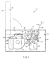
- a thermal printer 111 has a main body 113 having a first thermal head 112, a cover body 115 having a second thermal head 114, and a hinge mechanism 116 provided between the main body 113 and the cover body 115.
- the hinge mechanism 116 supports the cover body 115 so that the cover body 115 rotationally moves between a first state P1 where the cover body 115 covers the main body 113 and a second state P2 where the cover body 115 is opened with respect to the main body 113.
- the main body 113 has an enclosure 121 which can enclose roll paper 117 therein, the first thermal head 112 which can execute printing on a first face 117A of the roll paper 117, a second platen roller 122 which is supported rotatably to the enclosure 121 so as to correspond to the second thermal head 114 of the cover body 115, a driving section 123 which drives feeding of the roll paper 117, a reduction gear 125 which transmits a driving force of the driving section 123 to a first platen roller 124 and the second platen roller 122, a main body frame 126 which supports the hinge mechanism 116, a concave section 127 into which the first platen roller 124 is fitted when the cover body 115 is in the first state P1, a hook member 128 which is hooked with the cover body 115, and a part of a cutter mechanism 129.
- the roll paper 117 is made of, for example, both side thermal recording paper.
- the roll paper 117 is fitted into a recessed portion, not shown, in the enclosure 121 so as to be rotatably supported.
- the second platen roller 122 is supported rotatably to the enclosure 121 by a center impeller, for example.
- the driving section 123 is composed of a stepping motor, for example.
- the concave section 127 has a semicircle shape where its upper portion is opened. That is to say, the concave section 127 has a shape which is complementary with respect to the first platen roller 124 having a pillar shape.
- the hook member 128 can move rotationally about a shaft, not shown, provided to a lower end, for example.
- the hook member 128 has, for example, a torsion coil spring which is set between the hook member 128 and the enclosure 121. When a force is applied to the hook member 128 to a direction of separating from the second platen roller 122, a force is applied to the hook member 128 to a direction approaching the second platen roller 122 by counteraction of the torsion coil spring.
- the first thermal head 112 is arranged on a downstream side in a feeding direction of the roll paper 117 from the second platen roller 122.
- the first thermal head 112 is pushed towards the first platen roller 124 by a compression spring, not shown.
- the main body frame 126 has a long hole 126A along which the hinge mechanism 116 can slide in a horizontal direction.
- the cover body 115 has an upper frame 133, the second thermal head 114 for printing on a second face 117B opposite to the first face 117A of the roll paper 117, the first platen roller 124 which is rotatably supported to the upper frame 133 so as to correspond to the first thermal head 112, an outlet, not shown, for discharging the roll paper 117 to the outside, and a part of the cutter mechanism 129 which is arranged so as to be adjacent to the lower stream of the first platen roller 124.
- the first thermal head 112 is attached to the upper frame 133.
- the second platen roller 122 is rotatably supported to the upper frame 133 by a center impeller.
- the first thermal head 112 is arranged on the lower stream side in the feeding direction of the roll paper 117 with respect to the second platen roller 122.
- the upper frame 133 has a first frame 134 fixed to the hinge mechanism 116, a second frame 135 separated from the first frame 134, a connector 136 which connects the first frame 134 and the second frame 135 so that the second frame 135 can move rotationally with respect to the first frame 134, and a torsion coil spring 137 which is set between the first frame 134 and the second frame 135.
- a shaft section 138 around which the torsion coil spring 137 is wound is provided to the connector 136.
- the shaft section 138 functions as the center of the rotational movement of the second frame 135.
- the first frame 134 has a first pin 139 around which one end of the torsion coil spring 137 is wound, and an arm member 140 including an engagement pin 140A engaged with the hook member 128.
- the engagement pin 140A of the arm member 140 is arranged in the vicinity of the connector 136.
- the second thermal head 114 is rotatably retained in the first frame 134.
- the first platen roller 124 is rotatably retained in the second frame 135, and the second frame 135 is provided with a part of the cutter mechanism 129.
- the second frame 135 has a second pin 144 around which the other end of the torsion coil spring 137 is wound, and a regulating pin 145 which regulates the rotational moving range of the second frame 135.
- the second frame 135 can rotationally move about the shaft section 138 of the connector 136 with respect to the first frame 134.
- the second frame 135 is pushed to the direction of the main body 113 by the force of the torsion coil spring 137. In this state, the connector 136 butts against the regulating pin 145 so that the second frame 135 does not rotationally move toward the main body 113 any more.
- the second thermal head 114 has a head main body 148, a head frame 147 which supports the head main body 148 and can rotationally move about a pivot 146, and a compression spring 149 which pushes the head main body 148 against the second platen roller 122 of the main body 113.
- the driving section 123 drives so as to rotate the reduction gear 125 and to rotate the first platen roller 124 and the second platen roller 122.
- the roll paper 117 is sent toward the outlet by a frictional force generated between the first platen roller 124, the second platen roller 122 and the roll paper 117 due to the rotations of the first platen roller 124 and the second platen roller 122.
- the second thermal head 114 executes the printing process on the second face 117B of the roll paper 117.
- the first thermal head 112 then, executes the printing process on the first face 117A of the roll paper 117.
- the cutter mechanism 129 finally cuts the roll paper 117 into strip-shaped sheets, and the printing process of the thermal printer 111 is ended.
- the thermal printer 111 has a first locating mechanism 151 and a second locating mechanism 152 which locate the first platen roller 124 of the cover body 115 with respect to the first thermal head 112 of the main body 113, and locate the second thermal head 114 of the cover body 115 with respect to the second platen roller 122 of the main body 113.
- the first locating mechanism 151 includes the concave section 127 and the like of the main body 113.
- the second locating mechanism 152 includes the first platen roller 124 which is fitted into the concave section 127, the first frame 134, the second frame 135, the hook member 128 and the like.
- first locating mechanism 151 and the second locating mechanism 152 are explained below with reference to FIGS. 2 to 5 .
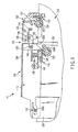
- FIG. 2 illustrates the second state P2 where the cover body 115 is opened with respect to the main body 113.
- the upper frame 133 is in a state that it is separated from the main body 113.
- the first frame 134 is pushed downward by the torsion coil spring 137.
- the connector 136 of the first frame 134 butts against the regulating pin 145 of the second frame 135, so that the rotational moving range of the second frame 135 is regulated.
- the first platen roller 124 is fitted into the concave section 127 as the first locating mechanism 151.
- the first locating mechanism 151 can locate the first platen roller 124 on the first thermal head 112.
- the second thermal head 114 is arranged in the vicinity of the second platen roller 122, so that the second thermal head 114 is roughly located.
- the engagement pin 140A of the second frame 135 butts against a clasp section 128A of the hook member 128 so as to push the hook member 128 to a direction where it is separated from the second platen roller 122.
- the first frame 134 and the second frame 135 of the upper frame 133 are brought into a so-called reverse bent state.
- the first platen roller 124 which is fitted into the concave section 127 included in the second locating mechanism 152 functions as a supporting point. That is to say, since the second frame 135 can rotationally move with respect to the first platen roller 124, the connector 136 can be rotationally moved about the first platen roller 124 so as to approach the main body 113. Simultaneously with the rotational movement of the second frame 135, the first frame 134 also rotationally moves.
- the connector 136 is made to close to the main body 113 by the rotational movement of the first frame 134 and the second frame 135.
- the engagement pin 140A of the arm member 140 passes the clasp section 128A of the hook member 128, and the hook member 128 moves to approach the second platen roller 122.
- an overlap L having a predetermined length is generated between the engagement pin 140A of the arm member 140 and the lower end of the clasp section 128A of the hook member 128.
- the second thermal head 114 is pushed against the second platen roller 122.
- the head frame 147 rotationally moves about the pivot 146.
- the compression spring 149 is compressed by the rotational movement of the head frame 147, and the head main body 148 is pushed against the second platen roller 122 by counteraction of the compression spring 149.
- the upper frame 133 recovers from the reversely bent state, and the first frame 134 and the second frame 135 are brought into a horizontal state.
- the hook member 128 as the second locating mechanism 152 is hooked on the engagement pin 140A of the arm member 140.
- a vertical position of the second thermal head 114 is determined.
- the upper frame 133 is in the horizontal state, the state that the first platen roller 124 is fitted into the concave section 127 of the first locating mechanism 151 is maintained.
- the concave section 127 of the first locating mechanism 151 determines a horizontal position of the second thermal head 114.
- the cover body 115 is brought into the first state P1 where it covers the main body 113 through such a process.
- the first locating mechanism 151 and the second locating mechanism 152 can locate the first platen roller 124 and the second thermal head 114.
- the thermal printer 111 since the second locating mechanism 152 as well as the first locating mechanism 151 is provided, the first thermal head 112 and the second thermal head 114 can be located accurately. Particularly, the second thermal head 114 is arranged in the vicinity of the second platen roller 122 by the first locating mechanism 151 in advance and then is located on the second platen roller 122 by the second locating mechanism 152. For this reason, the second thermal head 114 and the second platen roller 122 which are far from each other can be located more accurately than the case where they are located by a single locating mechanism at one time.
- the cover body 115 has the first frame 134 which supports the second thermal head 114, the second frame 135 which supports the first platen roller 124, and the connector 136 which connects the first frame 134 and the second frame 135 so that the second frame 135 can rotationally move with respect to the first frame 134.
- the divided type upper frame 133 in which the second frame 135 can be rotationally moved with respect to the first frame 134 can be constituted.
- the first locating mechanism 151 includes the concave section 127, and the concave section 127 locates the first platen roller 124 which is fitted thereinto with respect to the first thermal head 112, and determines the horizontal position of the second thermal head 114 with respect to the first platen roller 124 via the locating of the first platen roller 124. As a result, the position of the first platen roller 124 and the horizontal position of the second thermal head 114 can be determined collectively.
- the second locating mechanism 152 includes the first platen roller 124 which is fitted into the concave section 127, the first frame 134 and the second frame 135.
- the second locating mechanism 152 rotationally moves the first frame 134 and the second frame 135 about the first platen roller 124 fitted into the concave section 127 so that the connector 136 is made to be close to the main body 113, so as to locate the second thermal head 114 of the cover body 115 with respect to the second platen roller 122 of the main body 113.
- the second thermal head 114 can be located with the first platen roller 124 fitted into the concave section 127 of the main body 113 being used as the supporting point, the second thermal head 114 can be located more accurately.
- the second thermal head 114 Since the second thermal head 114 is located by using the rotational movements of the first frame 134 and the second frame 135 in the state that the first platen roller 124 is fixed, the second thermal head 114 can be made to be closer gradually to the second platen roller 122 of the main body 113. As a result, when the second thermal head 114 is located, the second thermal head 114 is prevented from swiftly butting against the second platen roller 122, thereby preventing a situation such that the second thermal head 114 is displaced due to an impact at the time of butting against the second platen roller 122.
- the second locating mechanism 152 includes the hook member 128 which is provided to the main body 113 so as to be hooked on the cover body 115 in the first state P1.
- the hook member 128 determines the vertical position of the second thermal head 114 with respect to the second platen roller 122. For this reason, the second locating mechanism 152 can determine the horizontal position and the vertical position of the second thermal head 114 in cooperation with the first locating mechanism 151.
- the hook member 128 is engaged with the arm member 140 positioned in the vicinity of the connector 136 between the first frame 134 and the second frame 135. For this reason, the hook member 128 can be engaged with the connector 136 whose moving distance is the longest, and the overlap L between the hook member 128 and the arm member 140 can be sufficiently provided.
- the engagement pin 140A does not disengage from the hook member 128, and the cover body 115 can be fixed to the main body 113 securely.
- the hook member 128 engages with the arm member 140 of the first frame 134 in the upper frame 133.
- the first platen roller 124 of the first frame 134 is fixed by the concave section 127 of the main body 113
- the second frame 135 is fixed by the hook member 128.
- fixing means for the main body 113 can be arranged on both the first frame 134 and the second frame 135, respectively, thereby holding the upper frame 133 to the main body 113 stably.
- the concave section 127 has a semicircular shape whose upper portion is opened. For this reason, the first locating mechanism 151 can be constituted by the simple structure.
- the semicircular concave section 127 determines the horizontal position and the vertical position of the first platen roller 124 simply and accurately.
- the semicircular concave section 127 can determine also the horizontal position of the second thermal head 114 accurately.
Landscapes
- Electronic Switches (AREA)
- Handling Of Sheets (AREA)
- Accessory Devices And Overall Control Thereof (AREA)
- Printers Characterized By Their Purpose (AREA)
Claims (8)
- Appareil d'impression (111), comprenant:un corps principal (113) ayant une première tête thermique (112) pouvant imprimer sur une première face de papier en rouleau (117A);un corps de couvercle (115) ayant une seconde tête thermique (114) pouvant imprimer sur une seconde face opposée à la première face du papier en rouleau (117A);un mécanisme de charnière (116) qui retient le corps de couvercle (115) de sorte que le corps de couvercle (115) peut se déplacer en rotation entre un premier état dans lequel il recouvre le corps principal (113) et un second état dans lequel il est ouvert par rapport au corps principal (113);un premier rouleau presseur (124) prévu sur le corps de couvercle (115) afin de correspondre à la première tête thermique (112) du corps principal (113);un second rouleau presseur (122) prévu sur le corps principal (113) afin de correspondre à la seconde tête thermique (114) du corps de couvercle (115);caractérisé en ce que:un premier mécanisme de positionnement (151) qui positionne le premier rouleau presseur (124) du corps de couvercle (115) par rapport à la première tête thermique (112) du corps principal (113) lorsque le corps de couvercle (115) passe du second état au premier état, et agence la seconde tête thermique (114) du corps de couvercle (115) à proximité du second rouleau presseur (122) du corps principal (113); etun second mécanisme de positionnement (152) qui positionne la seconde tête thermique (114) agencée à proximité du second rouleau presseur (122) par le premier mécanisme de positionnement (151) par rapport au second rouleau presseur (122) du corps principal (113), eten ce que le corps de couvercle (115) comprend:un premier bâti (134) qui est fixé sur le mécanisme de charnière (116) et supporte la seconde tête thermique (114);un second bâti (135) qui supporte le premier rouleau presseur (124); etun connecteur (136) qui raccorde le premier bâti (134) et le second bâti (135) de sorte que le second bâti (135) peut se déplacer en rotation par rapport au premier bâti (134).
- Appareil d'impression (111) selon la revendication 1, caractérisé en ce que:le premier mécanisme de positionnement (151) comprend une section concave (127) qui est prévue sur le corps principal (113) de sorte que le premier rouleau presseur (124) du corps de couvercle (115) est monté dans la section concave (127) dans le premier état,la section concave (127) positionne le premier rouleau presseur (124) monté, par rapport à la première tête thermique (112), et détermine une position horizontale de la seconde tête thermique (114) par rapport au second rouleau presseur (122) via le positionnement du premier rouleau presseur (124).
- Appareil d'impression (111) selon la revendication 2, caractérisé en ce que:le second mécanisme de positionnement (152) comprend un premier rouleau presseur (124) qui est monté dans la section concave (127), le premier bâti (134), le second bâti (135) et le connecteur (136), et déplace en rotation le premier bâti (134) et le second bâti (135) autour du premier rouleau presseur (124) monté dans la section concave (127) de sorte que le connecteur (136) se rapproche du corps principal (113), afin de positionner la seconde tête thermique (114) du corps de couvercle (115) par rapport au second rouleau presseur (122) du corps principal (113).
- Appareil d'impression (111) selon la revendication 3, caractérisé en ce que:le second mécanisme de positionnement (152) comprend un élément de crochet (128) qui est prévu sur le corps principal (113) et est accroché sur le corps de couvercle (115) dans le premier état, etl'élément de crochet (128) détermine une position verticale de la seconde tête thermique (114) par rapport au second rouleau presseur (122).
- Appareil d'impression (111) selon la revendication 4, caractérisé en ce que l'élément de crochet (128) est accroché à proximité du connecteur (136) du corps de couvercle (115).
- Appareil d'impression (111) selon la revendication 5, caractérisé en ce que l'élément de crochet (128) est accroché sur le premier bâti (134) du corps de couvercle (115).
- Appareil d'impression (111) selon la revendication 2, caractérisé en ce que la section concave (127) a une forme semi-circulaire dont la partie supérieure est ouverte.
- Appareil d'impression (111) selon la revendication 1, caractérisé en ce que la seconde tête thermique (114) est détachable du corps de couvercle (115).
Applications Claiming Priority (5)
| Application Number | Priority Date | Filing Date | Title |
|---|---|---|---|
| JP2006151693A JP2007320121A (ja) | 2006-05-31 | 2006-05-31 | 両面印刷サーマルプリンタ及びサーマルヘッド保持方法 |
| JP2006178947A JP4247251B2 (ja) | 2006-06-29 | 2006-06-29 | サーマルプリンタ |
| JP2006178958A JP4616216B2 (ja) | 2006-06-29 | 2006-06-29 | 印刷装置 |
| JP2006178953A JP2008006680A (ja) | 2006-06-29 | 2006-06-29 | サーマルプリンタ |
| EP07109273A EP1862322B1 (fr) | 2006-05-31 | 2007-05-31 | Imprimante recto-verso |
Related Parent Applications (2)
| Application Number | Title | Priority Date | Filing Date |
|---|---|---|---|
| EP07109273 Previously-Filed-Application | 2007-05-31 | ||
| EP07109273.8 Division | 2007-05-31 |
Publications (2)
| Publication Number | Publication Date |
|---|---|
| EP2284012A1 EP2284012A1 (fr) | 2011-02-16 |
| EP2284012B1 true EP2284012B1 (fr) | 2013-10-23 |
Family
ID=38436773
Family Applications (2)
| Application Number | Title | Priority Date | Filing Date |
|---|---|---|---|
| EP07109273A Active EP1862322B1 (fr) | 2006-05-31 | 2007-05-31 | Imprimante recto-verso |
| EP10175190.7A Active EP2284012B1 (fr) | 2006-05-31 | 2007-05-31 | Imprimante recto-verso |
Family Applications Before (1)
| Application Number | Title | Priority Date | Filing Date |
|---|---|---|---|
| EP07109273A Active EP1862322B1 (fr) | 2006-05-31 | 2007-05-31 | Imprimante recto-verso |
Country Status (3)
| Country | Link |
|---|---|
| US (1) | US7828490B2 (fr) |
| EP (2) | EP1862322B1 (fr) |
| CN (1) | CN101722741B (fr) |
Families Citing this family (23)
| Publication number | Priority date | Publication date | Assignee | Title |
|---|---|---|---|---|
| US7914218B2 (en) * | 2006-06-29 | 2011-03-29 | Toshiba Tec Kabushiki Kaisha | Thermal printer and printing device |
| DE602007014250D1 (de) * | 2006-06-29 | 2011-06-09 | Ncr Corp | Drucker |
| JP5001057B2 (ja) * | 2007-04-23 | 2012-08-15 | 富士通コンポーネント株式会社 | プリンタ装置 |
| JP4910965B2 (ja) * | 2007-09-28 | 2012-04-04 | セイコーエプソン株式会社 | サーマルプリンタ |
| JP5082749B2 (ja) * | 2007-10-15 | 2012-11-28 | セイコーエプソン株式会社 | プリンタ |
| EP2050902A1 (fr) * | 2007-10-18 | 2009-04-22 | USM Holding AG | Fermeture de meuble mécatronique |
| US8721208B2 (en) * | 2008-02-25 | 2014-05-13 | Avery Dennison Corporation | Portable printer and methods |
| JP5107322B2 (ja) * | 2009-09-10 | 2012-12-26 | 東芝テック株式会社 | 印刷装置 |
| JP5240243B2 (ja) * | 2010-06-17 | 2013-07-17 | ブラザー工業株式会社 | 画像記録装置 |
| GB201017594D0 (en) * | 2010-10-19 | 2010-12-01 | Domino Printing Sciences Plc | Printing apparatus |
| CN102463746B (zh) * | 2010-11-19 | 2014-04-02 | 山东新北洋信息技术股份有限公司 | 打印头组件及使用该组件的打印机 |
| JP5438706B2 (ja) | 2011-02-28 | 2014-03-12 | 東芝テック株式会社 | 画像形成装置及びヘッド離間制御方法 |
| JP5757768B2 (ja) * | 2011-04-04 | 2015-07-29 | 富士通コンポーネント株式会社 | プリンタ |
| EP2511100B1 (fr) * | 2011-04-11 | 2014-11-05 | Wincor Nixdorf International GmbH | Imprimante à double face pour imprimer les reçus sur un papier thermique |
| GB2493357B (en) * | 2011-08-01 | 2018-05-09 | Able Systems Ltd | A printer |
| CN103917375B (zh) * | 2011-08-15 | 2016-07-27 | 录象射流技术公司 | 热转印打印机 |
| US9604474B2 (en) * | 2014-09-02 | 2017-03-28 | Seiko Instruments Inc. | Printing unit and printer |
| JP6422333B2 (ja) * | 2014-09-02 | 2018-11-14 | セイコーインスツル株式会社 | 印字ユニット及びプリンタ |
| CN104442015B (zh) * | 2014-11-14 | 2016-04-27 | 南京奥拓电子科技有限公司 | 一种热敏打印机及其放纸装置 |
| US9908351B1 (en) * | 2017-02-27 | 2018-03-06 | Datamax-O'neil Corporation | Segmented enclosure |
| JP6908396B2 (ja) * | 2017-03-01 | 2021-07-28 | 東芝テック株式会社 | プリンタ |
| JP7294946B2 (ja) * | 2019-08-20 | 2023-06-20 | 東芝テック株式会社 | プリンタ |
| CN113334939A (zh) * | 2021-04-22 | 2021-09-03 | 厦门汉印电子技术有限公司 | 一种打印机结构 |
Family Cites Families (40)
| Publication number | Priority date | Publication date | Assignee | Title |
|---|---|---|---|---|
| JPS588668A (ja) | 1981-07-08 | 1983-01-18 | Shinko Electric Co Ltd | 感熱式印刷装置による両面印刷方法 |
| JPS613765A (ja) | 1984-06-18 | 1986-01-09 | Konishiroku Photo Ind Co Ltd | 熱転写プリンタ |
| JPS62286767A (ja) | 1986-06-05 | 1987-12-12 | Canon Inc | 熱転写プリンタ |
| US5044801A (en) * | 1988-12-15 | 1991-09-03 | Tokyo Electric Co., Ltd. | Printing apparatus |
| JPH082494B2 (ja) | 1989-06-06 | 1996-01-17 | 東レ株式会社 | 繊維強化金属複合材料の製造方法 |
| JPH0351149A (ja) | 1989-07-20 | 1991-03-05 | Fujitsu General Ltd | 熱転写式プリンタ |
| JPH0483675A (ja) | 1990-07-26 | 1992-03-17 | Toshiba Corp | 紙葉類印刷装置 |
| JP2770917B2 (ja) | 1991-07-17 | 1998-07-02 | キヤノン株式会社 | 情報記録再生装置 |
| JPH0624082A (ja) | 1991-10-03 | 1994-02-01 | Ricoh Co Ltd | 両面印字装置 |
| JPH06155856A (ja) | 1992-11-16 | 1994-06-03 | Asahi Optical Co Ltd | 画像形成装置 |
| US5284816A (en) * | 1992-11-19 | 1994-02-08 | Eastman Kodak Company | Two-sided thermal printing system |
| JPH0789140A (ja) | 1993-09-21 | 1995-04-04 | Hitachi Ltd | プリンタ装置 |
| JP3545830B2 (ja) * | 1995-04-27 | 2004-07-21 | 東芝テック株式会社 | ラベルプリンタ |
| US6118469A (en) * | 1995-11-21 | 2000-09-12 | Seiko Epson Corporation | Thermal printer |
| JPH09174912A (ja) | 1995-12-26 | 1997-07-08 | Toshiba Corp | 感熱印刷装置 |
| JPH09233256A (ja) | 1996-02-23 | 1997-09-05 | Ricoh Co Ltd | ファクシミリ装置 |
| JPH1076713A (ja) | 1996-09-03 | 1998-03-24 | Sony Corp | 両面同時印画プリンタ装置 |
| JPH10109456A (ja) | 1996-10-04 | 1998-04-28 | Matsushita Electric Ind Co Ltd | 印字装置 |
| JP3623084B2 (ja) * | 1996-10-18 | 2005-02-23 | 株式会社リコー | 感熱性粘着ラベルの熱活性化方法及び感熱性粘着ラベルの貼り付け方法 |
| JP3507644B2 (ja) | 1997-02-24 | 2004-03-15 | 東芝テック株式会社 | ライン型サーマルヘッドの支持構造 |
| JPH115320A (ja) | 1997-06-17 | 1999-01-12 | Tec Corp | ラインサーマルプリンタ |
| US5961228A (en) * | 1997-08-22 | 1999-10-05 | Paxar Corporation | Modular printer |
| JP3936782B2 (ja) | 1997-09-08 | 2007-06-27 | 富士インパルス株式会社 | 印刷装置 |
| JPH11286147A (ja) * | 1998-04-02 | 1999-10-19 | Nec Yonezawa Ltd | 両面印刷機構 |
| JP2000118060A (ja) | 1998-10-14 | 2000-04-25 | Star Micronics Co Ltd | サーマルプリンタ |
| JP2000203122A (ja) | 1999-01-12 | 2000-07-25 | Toshiba Tec Corp | プリンタ |
| JP3614314B2 (ja) * | 1999-03-25 | 2005-01-26 | セイコーエプソン株式会社 | プリンタ |
| US6406200B2 (en) * | 1999-07-30 | 2002-06-18 | Inovise Medical, Inc. | Printer assembly with lateral and longitudinal self-alignment |
| JP2001071569A (ja) | 1999-09-02 | 2001-03-21 | Alps Electric Co Ltd | サーマルプリンタ |
| JP2001199095A (ja) | 2000-01-18 | 2001-07-24 | Alps Electric Co Ltd | 両面印刷プリンタ |
| US6565273B2 (en) * | 2000-04-19 | 2003-05-20 | Seiko Epson Corporation | Printer that accomodates rolled paper having various widths |
| JP2001341371A (ja) | 2000-06-05 | 2001-12-11 | Seiko Epson Corp | プリンタ |
| JP4580088B2 (ja) | 2000-11-10 | 2010-11-10 | シチズンホールディングス株式会社 | ラインサーマルプリンタ |
| JP3840396B2 (ja) | 2001-10-18 | 2006-11-01 | アルプス電気株式会社 | サーマルプリンタ |
| JP3885564B2 (ja) | 2001-11-16 | 2007-02-21 | セイコーエプソン株式会社 | プリンタ及びプリンタユニット |
| US6759366B2 (en) * | 2001-12-18 | 2004-07-06 | Ncr Corporation | Dual-sided imaging element |
| US6784906B2 (en) * | 2001-12-18 | 2004-08-31 | Ncr Corporation | Direct thermal printer |
| US7125182B2 (en) | 2004-02-17 | 2006-10-24 | Paxar Americas, Inc. | Printer |
| JP2006051734A (ja) | 2004-08-13 | 2006-02-23 | Nidec Copal Corp | サーマルプリンタ |
| US9024986B2 (en) | 2006-03-07 | 2015-05-05 | Ncr Corporation | Dual-sided thermal pharmacy script printing |
-
2007
- 2007-03-05 US US11/681,907 patent/US7828490B2/en active Active
- 2007-05-31 CN CN2009102119777A patent/CN101722741B/zh active Active
- 2007-05-31 EP EP07109273A patent/EP1862322B1/fr active Active
- 2007-05-31 EP EP10175190.7A patent/EP2284012B1/fr active Active
Also Published As
| Publication number | Publication date |
|---|---|
| US20080003038A1 (en) | 2008-01-03 |
| CN101722741B (zh) | 2012-11-28 |
| EP1862322A1 (fr) | 2007-12-05 |
| CN101722741A (zh) | 2010-06-09 |
| EP1862322B1 (fr) | 2011-07-27 |
| EP2284012A1 (fr) | 2011-02-16 |
| US7828490B2 (en) | 2010-11-09 |
Similar Documents
| Publication | Publication Date | Title |
|---|---|---|
| EP2284012B1 (fr) | Imprimante recto-verso | |
| KR101505205B1 (ko) | 커터가 달린 프린터 | |
| US8506190B2 (en) | Cutter mechanism and printer with a cutter | |
| CN101574864B (zh) | 打印装置 | |
| EP1095782A2 (fr) | Imprimante | |
| EP1950049B1 (fr) | Appareil de traitement de feuilles en continu et procédé pour l'installation d'un corps de rouleau dans un appareil de traitement de feuilles en continu | |
| TWI680888B (zh) | 列印單元及熱列印機 | |
| JP5469469B2 (ja) | プリンタ | |
| US20080199239A1 (en) | Sheet cutting device and printer | |
| CN204506144U (zh) | 带切割器的打印机 | |
| JP2007038313A (ja) | 紙切断装置およびプリンタ | |
| JP6703763B2 (ja) | シート搬送装置及び画像形成装置 | |
| KR102871699B1 (ko) | 인자 유닛 및 서멀 프린터 | |
| US7410315B2 (en) | Paper discharge mechanism for a printer, and a printer | |
| EP2821234A1 (fr) | Dispositif d'imprimante | |
| EP2927006B1 (fr) | Imprimante | |
| US8550734B2 (en) | Transportation guide mechanism and recording device having the same | |
| JP5517545B2 (ja) | プリンタ装置 | |
| JP4247251B2 (ja) | サーマルプリンタ | |
| JP2000108439A (ja) | ロール紙用プリンタ | |
| JP5382068B2 (ja) | プリンタ | |
| JP2013233778A (ja) | 印刷装置 | |
| JP5850707B2 (ja) | プリンタ | |
| JP6044250B2 (ja) | 記録媒体カセット、記録装置 | |
| JP2000103549A (ja) | プリンタのロール紙装填機構 |
Legal Events
| Date | Code | Title | Description |
|---|---|---|---|
| PUAI | Public reference made under article 153(3) epc to a published international application that has entered the european phase |
Free format text: ORIGINAL CODE: 0009012 |
|
| 17P | Request for examination filed |
Effective date: 20100903 |
|
| AC | Divisional application: reference to earlier application |
Ref document number: 1862322 Country of ref document: EP Kind code of ref document: P |
|
| AK | Designated contracting states |
Kind code of ref document: A1 Designated state(s): DE FR GB |
|
| GRAP | Despatch of communication of intention to grant a patent |
Free format text: ORIGINAL CODE: EPIDOSNIGR1 |
|
| INTG | Intention to grant announced |
Effective date: 20130503 |
|
| GRAS | Grant fee paid |
Free format text: ORIGINAL CODE: EPIDOSNIGR3 |
|
| GRAA | (expected) grant |
Free format text: ORIGINAL CODE: 0009210 |
|
| RIN1 | Information on inventor provided before grant (corrected) |
Inventor name: EOKA, KENJI Inventor name: TAKAHASHI, KOUSUKE Inventor name: SANADA, TSUYOSHI Inventor name: NIHASHI, KIYOTAKA Inventor name: HIYOSHI, TAKESHI Inventor name: SUZUKI, AKIRA |
|
| AC | Divisional application: reference to earlier application |
Ref document number: 1862322 Country of ref document: EP Kind code of ref document: P |
|
| AK | Designated contracting states |
Kind code of ref document: B1 Designated state(s): DE FR GB |
|
| REG | Reference to a national code |
Ref country code: GB Ref legal event code: FG4D |
|
| REG | Reference to a national code |
Ref country code: DE Ref legal event code: R096 Ref document number: 602007033525 Country of ref document: DE Effective date: 20131219 |
|
| REG | Reference to a national code |
Ref country code: DE Ref legal event code: R097 Ref document number: 602007033525 Country of ref document: DE |
|
| PLBE | No opposition filed within time limit |
Free format text: ORIGINAL CODE: 0009261 |
|
| STAA | Information on the status of an ep patent application or granted ep patent |
Free format text: STATUS: NO OPPOSITION FILED WITHIN TIME LIMIT |
|
| 26N | No opposition filed |
Effective date: 20140724 |
|
| REG | Reference to a national code |
Ref country code: DE Ref legal event code: R097 Ref document number: 602007033525 Country of ref document: DE Effective date: 20140724 |
|
| REG | Reference to a national code |
Ref country code: FR Ref legal event code: PLFP Year of fee payment: 10 |
|
| REG | Reference to a national code |
Ref country code: FR Ref legal event code: PLFP Year of fee payment: 11 |
|
| REG | Reference to a national code |
Ref country code: FR Ref legal event code: PLFP Year of fee payment: 12 |
|
| REG | Reference to a national code |
Ref country code: FR Ref legal event code: PLFP Year of fee payment: 17 |
|
| PGFP | Annual fee paid to national office [announced via postgrant information from national office to epo] |
Ref country code: DE Payment date: 20250402 Year of fee payment: 19 |
|
| PGFP | Annual fee paid to national office [announced via postgrant information from national office to epo] |
Ref country code: GB Payment date: 20250401 Year of fee payment: 19 |
|
| PGFP | Annual fee paid to national office [announced via postgrant information from national office to epo] |
Ref country code: FR Payment date: 20250401 Year of fee payment: 19 |