EP2284485B1 - Appareil de mesure de coordonnées et procédé de mesure à l'aide d'un appareil de mesure de coordonnées - Google Patents
Appareil de mesure de coordonnées et procédé de mesure à l'aide d'un appareil de mesure de coordonnées Download PDFInfo
- Publication number
- EP2284485B1 EP2284485B1 EP10185234.1A EP10185234A EP2284485B1 EP 2284485 B1 EP2284485 B1 EP 2284485B1 EP 10185234 A EP10185234 A EP 10185234A EP 2284485 B1 EP2284485 B1 EP 2284485B1
- Authority
- EP
- European Patent Office
- Prior art keywords
- sensors
- temperature
- coordinate measuring
- measuring
- several
- Prior art date
- Legal status (The legal status is an assumption and is not a legal conclusion. Google has not performed a legal analysis and makes no representation as to the accuracy of the status listed.)
- Expired - Lifetime
Links
Images


Classifications
-
- G—PHYSICS
- G01—MEASURING; TESTING
- G01B—MEASURING LENGTH, THICKNESS OR SIMILAR LINEAR DIMENSIONS; MEASURING ANGLES; MEASURING AREAS; MEASURING IRREGULARITIES OF SURFACES OR CONTOURS
- G01B11/00—Measuring arrangements characterised by the use of optical techniques
- G01B11/02—Measuring arrangements characterised by the use of optical techniques for measuring length, width or thickness
- G01B11/03—Measuring arrangements characterised by the use of optical techniques for measuring length, width or thickness by measuring coordinates of points
-
- G—PHYSICS
- G01—MEASURING; TESTING
- G01B—MEASURING LENGTH, THICKNESS OR SIMILAR LINEAR DIMENSIONS; MEASURING ANGLES; MEASURING AREAS; MEASURING IRREGULARITIES OF SURFACES OR CONTOURS
- G01B11/00—Measuring arrangements characterised by the use of optical techniques
- G01B11/24—Measuring arrangements characterised by the use of optical techniques for measuring contours or curvatures
- G01B11/245—Measuring arrangements characterised by the use of optical techniques for measuring contours or curvatures using a plurality of fixed, simultaneously operating transducers
-
- G—PHYSICS
- G01—MEASURING; TESTING
- G01B—MEASURING LENGTH, THICKNESS OR SIMILAR LINEAR DIMENSIONS; MEASURING ANGLES; MEASURING AREAS; MEASURING IRREGULARITIES OF SURFACES OR CONTOURS
- G01B21/00—Measuring arrangements or details thereof, where the measuring technique is not covered by the other groups of this subclass, unspecified or not relevant
- G01B21/02—Measuring arrangements or details thereof, where the measuring technique is not covered by the other groups of this subclass, unspecified or not relevant for measuring length, width, or thickness
- G01B21/04—Measuring arrangements or details thereof, where the measuring technique is not covered by the other groups of this subclass, unspecified or not relevant for measuring length, width, or thickness by measuring coordinates of points
- G01B21/045—Correction of measurements
-
- G—PHYSICS
- G01—MEASURING; TESTING
- G01B—MEASURING LENGTH, THICKNESS OR SIMILAR LINEAR DIMENSIONS; MEASURING ANGLES; MEASURING AREAS; MEASURING IRREGULARITIES OF SURFACES OR CONTOURS
- G01B5/00—Measuring arrangements characterised by the use of mechanical techniques
- G01B5/0011—Arrangements for eliminating or compensation of measuring errors due to temperature or weight
- G01B5/0014—Arrangements for eliminating or compensation of measuring errors due to temperature or weight due to temperature
Definitions
- the invention relates to a method for measuring workpiece geometries with a coordinate measuring machine with movable track axes and one or more sensors for detecting measuring points on the workpiece surfaces.
- the invention relates to a coordinate measuring machine for measuring workpiece geometries, comprising a plurality of movable track axes and a plurality of sensors for detecting measuring points on at least one surface of the workpiece.
- Coordinate measuring machines are understood to mean measuring devices with one or more mechanically moved axes for measuring geometric properties of workpieces or measuring objects. These coordinate measuring machines are equipped with sensors for recording the geometrical measuring points on the workpiece surfaces. Prior art are predominantly coordinate measuring machines with purely tactile sensors, d. H. the measuring point is generated by touching the workpiece surface with a tactile probe. Also known are coordinate measuring machines with optical sensors, in which the measuring points are determined by an optoelectronic image processing or a laser distance sensor. Coordinate measuring machines are also known in which individual ones of these sensors are combined with one another and thus extended possibilities for the user are given.
- the coordinate measuring machine used for the respective measuring task is not optimally configured, so that consequently several devices of different types are necessary.
- Coordinate measuring devices for measuring workpiece geometries are to be taken with a plurality of movable track axes, wherein each coordinate measuring machine has a sensor for detecting measuring points on a workpiece surface.
- temperature sensors are arranged on the elements connecting the respective sensor to a base frame of the coordinate measuring machine or on the sensor itself.
- a multisensor coordinate measuring machine which comprises a tactile button, a video button and a laser probe.
- a multisensor coordinate measuring machine is out of the DE 197 47 027 A1 known.
- the present invention is i.a. the task is to allow precise measurements of the workpiece geometries, in particular to ensure that temperature-induced measurement errors are omitted.
- Components are taken into account in the calculation of the measurement points, which is detected by the various sensors.
- a coordinate measuring machine for measuring workpiece geometries comprising a plurality of movable track axes and a plurality of sensors for detecting measuring points on at least one surface of the workpiece is characterized in that the sensors are connected in the coordinate measuring machine via connecting elements, the one or more temperature measuring points for determining temperature-induced changes in position between have the sensors, wherein the connecting elements are equipped with one or more temperature sensors, which are connected to an evaluation of the coordinate measuring machine.
- a coordinate measuring machine 10 which is equipped with the sensor or sensors required for the respective solution of a measuring task.
- the sensors can either be mounted or disassembled or can be automatically switched on and off during operation by means of corresponding sensor change systems.
- a flexible measurement of complex workpiece geometries is possible.
- the invention will not be abandoned if a corresponding number of selected sensors are permanently mounted on the device to measure objects in this configuration.
- the well-known and again in the Fig. 1 reproduced principle of a coordinate measuring machine 10 includes a z. B. granite base frame 12 with measuring table 14, on which an object to be measured 16 is positioned to measure its surface properties.
- a portal 18 is adjustable in the Y direction.
- columns or uprights 20, 22 are slidably supported on the base frame 12.
- a traverse 24 goes out, along which a carriage is movable, which in turn receives a quill or column 26 which is adjustable in the Z direction.
- a sensor 30 is formed in the embodiment as a tactile sensor, which then when the sleeve 26 includes an image processing sensor, tactile-optically measures.
- the coordinate measuring machine 10 can have a sensor changer, as is the case in principle Fig. 2 can be seen.
- a plurality of sensors can each optionally be provided with the coordinate measuring machine via an exchange interface and exchanged by hand or by automatic retrieval of the coordinate measuring machine at a parking station.
- Fig. 2 is a section of a coordinate measuring machine with a sleeve 32 reproduced in plan view.
- the sensors connectable to the quill are identified by the reference numerals 34, 36, 38.
- the sensors 34, 36, 38 may be designed optically or tactile, to name only sensor types.
- the coordinate measuring machine, ie the quill 32 is adjustable in the YXZ direction in order to carry out an exchange of the sensors 34, 36, 38.
- the parking station 42 or the Tasterwechslersystem can be adjusted by an adjustment axis 44 so that the probe changer 42 is arranged in non-operation outside the measuring volume of the coordinate measuring machine.
- the camera of the image processing sensor is selected with a larger resolution (number of pixels) than the resolution of the monitor used or the monitor section used for the image display. Furthermore, the camera can be equipped with random access to certain sections of the overall picture. It is then possible that in the live image or observation image of the coordinate measuring machine only a section of the overall image is displayed, which is enlarged to the format of the respective display window or monitor. As a result, the user has the option to select zoomed sections of the image according to his ideas.
- the enlargement The measurement object and the monitor image can be controlled by changing the selected section of the camera image by the software, or the live image can also be displayed in the same way.
- the magnification between the measurement object and the monitor image can be changed by changing the selected section of the camera image.
- This can optionally be operated by a rotary knob, which is integrated in the control system of the coordinate measuring machine, or via a software controller. It is also possible that when using a high-resolution camera, the image or the image is displayed only in the lower resolution of the monitor, in the background, however, the full resolution of the camera for digital image processing is used to increase the accuracy.
- optical magnification of the imaging optics of the image processing here is relatively low (typically 1-fold, but at most 5-fold) and the representation of only a section of the high-resolution camera image on the lower-resolution monitor, the optical effect of higher magnification is achieved.
- Fig. 3 is a section of a coordinate measuring machine arranged.
- the object to be measured 16 is shown on the measuring table 12.
- an imaging lens 46 and a camera such as CCD camera 48 are arranged, which is connected via a computer 50 to a monitor 52. Due to the hardware of the computer 50, it is possible to computationally adjust the resolution between the camera 48 and the monitor 52 to z. B. to use a larger camera resolution than can be reproduced by the monitor 52.
- the camera 58 is equipped with additional post-magnification optics 62 to define the magnification.
- the optical splitters or mirrors used in the beam path, which are used in the Fig. 3 are denoted by the reference numerals 56 and 64 are designed so that after the division all affected cameras 48, 58 and 60 sensors are equipped with the same light intensity. Via an additional optical divider 66 and a lighting device 68, an integrated bright field incident light is realized.
- an even higher-resolution camera image can be displayed by re-sampling from the respectively acquired camera image with the purpose of displaying an even higher magnification.
- additional pixels are determined by interpolation between real measured pixels.
- Coordinate measuring machines are generally exposed to different operating temperatures at the place of use. If several sensors are attached to the coordinate measuring machine, this will cause the positions between the different sensors to change thermally. This leads to measurement errors. According to the invention, to compensate for this, the temperature of the mechanical assemblies required for mounting the various sensors is measured at one or more locations, and the expansion of the corresponding mechanical components is taken into account in the calculation of the measuring points detected by the various sensors.
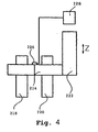
- Fig. 4 an example of an arrangement with two sensors 218, 220 on a Z-axis 222 of a coordinate measuring machine.
- the sensors 218, 220 are one or more-28. October 2013-50576 new description pages 1 to 8 re connecting elements 224 connected to each other and the Z-axis 222.
- a temperature sensor 226 the temperature of the connecting element or elements 224 is measured continuously during the measurement, and the corresponding change in length is corrected by an evaluation computer 228 and taken into account for the measurement results.
Landscapes
- Physics & Mathematics (AREA)
- General Physics & Mathematics (AREA)
- Length Measuring Devices By Optical Means (AREA)
- Length Measuring Devices With Unspecified Measuring Means (AREA)
- A Measuring Device Byusing Mechanical Method (AREA)
- Analysing Materials By The Use Of Radiation (AREA)
Claims (4)
- Procédé pour mesurer des géométries de pièces d'oeuvre avec un appareil de mesure de coordonnées (10) doté d'axes de translation (222) mobiles et de plusieurs capteurs (34, 36, 38, 118, 120) pour saisir des points de mesure sur les surfaces de la pièce d'oeuvre,
caractérisé en ce
que la température des éléments de liaison (224) mécaniques, au moyen desquels sont reliés des capteurs (34, 36, 38, 118, 120), est mesurée à un ou plusieurs point(s) et prise en compte afin de compenser des facteurs d'erreur. - Procédé selon la revendication 1,
caractérisé en ce
que pour compenser des facteurs d'erreur dus à des variations de température au lieu d'implantation de l'appareil de mesure de coordonnées (10), la température des éléments de liaison (224) mécaniques qui servent à relier les différents capteurs (34, 36, 38, 118, 120), est mesurée à un ou plusieurs point(s), et que la dilatation des composants mécaniques correspondants est prise en compte dans le calcul des points de mesure saisis par les différents capteurs. - Procédé selon la revendication 1 ou 2,
caractérisé en ce
que la compensation de température a lieu sous forme linéaire multiplicative. - Appareil de mesure de coordonnées pour mesurer des géométries de pièces d'oeuvre, comprenant plusieurs axes de translation (222) mobiles ainsi que des capteurs (218, 220) pour saisir des points de mesure sur au moins une surface de la pièce d'oeuvre,
caractérisé en ce
que les capteurs (218, 220) dans l'appareil de mesure de coordonnées sont reliés par des éléments de liaison (224) qui présentent un point de mesure de température ou plusieurs points de mesure de température pour déterminer des modifications de position entre les capteurs dues à la température, sachant que les éléments de liaison (224) sont équipés d'un ou de plusieurs capteurs(s) de température (226), destiné(s) à mesurer la température des éléments de liaison (224) au point de mesure de température ou aux points de mesure de température, et qui est/sont relié(s) à un ordinateur d'analyse (228) de l'appareil de mesure de coordonnées.
Applications Claiming Priority (3)
| Application Number | Priority Date | Filing Date | Title |
|---|---|---|---|
| DE102004061151 | 2004-12-16 | ||
| EP10165895.3A EP2224204B1 (fr) | 2004-12-16 | 2005-12-16 | Procédé de mesure de la géometrie d'un objet à l'aide d'un appareil de mesure de coordonnées |
| EP05819689A EP1846729A1 (fr) | 2004-12-16 | 2005-12-16 | Appareil de mesure de coordonnees et procede de mesure au moyen d'un appareil de mesure de coordonnees |
Related Parent Applications (5)
| Application Number | Title | Priority Date | Filing Date |
|---|---|---|---|
| EP10165895.3A Division EP2224204B1 (fr) | 2004-12-16 | 2005-12-16 | Procédé de mesure de la géometrie d'un objet à l'aide d'un appareil de mesure de coordonnées |
| EP10165895.3A Division-Into EP2224204B1 (fr) | 2004-12-16 | 2005-12-16 | Procédé de mesure de la géometrie d'un objet à l'aide d'un appareil de mesure de coordonnées |
| EP05819689A Division EP1846729A1 (fr) | 2004-12-16 | 2005-12-16 | Appareil de mesure de coordonnees et procede de mesure au moyen d'un appareil de mesure de coordonnees |
| EP05819689.0 Division | 2005-12-16 | ||
| EP10165895.3 Division | 2010-06-14 |
Publications (3)
| Publication Number | Publication Date |
|---|---|
| EP2284485A2 EP2284485A2 (fr) | 2011-02-16 |
| EP2284485A3 EP2284485A3 (fr) | 2013-05-15 |
| EP2284485B1 true EP2284485B1 (fr) | 2015-09-16 |
Family
ID=35985193
Family Applications (5)
| Application Number | Title | Priority Date | Filing Date |
|---|---|---|---|
| EP10185239.0A Expired - Lifetime EP2284486B1 (fr) | 2004-12-16 | 2005-12-16 | Appareil de mesure de coordonnées et procédé de mesure à l'aide d'un appareil de mesure de coordonnées |
| EP10185234.1A Expired - Lifetime EP2284485B1 (fr) | 2004-12-16 | 2005-12-16 | Appareil de mesure de coordonnées et procédé de mesure à l'aide d'un appareil de mesure de coordonnées |
| EP10185231.7A Expired - Lifetime EP2284480B1 (fr) | 2004-12-16 | 2005-12-16 | Appareil de mesure de coordonnées et procédé de mesure à l'aide d'un appareil de mesure de coordonnées |
| EP10165895.3A Expired - Lifetime EP2224204B1 (fr) | 2004-12-16 | 2005-12-16 | Procédé de mesure de la géometrie d'un objet à l'aide d'un appareil de mesure de coordonnées |
| EP05819689A Ceased EP1846729A1 (fr) | 2004-12-16 | 2005-12-16 | Appareil de mesure de coordonnees et procede de mesure au moyen d'un appareil de mesure de coordonnees |
Family Applications Before (1)
| Application Number | Title | Priority Date | Filing Date |
|---|---|---|---|
| EP10185239.0A Expired - Lifetime EP2284486B1 (fr) | 2004-12-16 | 2005-12-16 | Appareil de mesure de coordonnées et procédé de mesure à l'aide d'un appareil de mesure de coordonnées |
Family Applications After (3)
| Application Number | Title | Priority Date | Filing Date |
|---|---|---|---|
| EP10185231.7A Expired - Lifetime EP2284480B1 (fr) | 2004-12-16 | 2005-12-16 | Appareil de mesure de coordonnées et procédé de mesure à l'aide d'un appareil de mesure de coordonnées |
| EP10165895.3A Expired - Lifetime EP2224204B1 (fr) | 2004-12-16 | 2005-12-16 | Procédé de mesure de la géometrie d'un objet à l'aide d'un appareil de mesure de coordonnées |
| EP05819689A Ceased EP1846729A1 (fr) | 2004-12-16 | 2005-12-16 | Appareil de mesure de coordonnees et procede de mesure au moyen d'un appareil de mesure de coordonnees |
Country Status (4)
| Country | Link |
|---|---|
| US (1) | US20100014099A1 (fr) |
| EP (5) | EP2284486B1 (fr) |
| JP (2) | JP2008524565A (fr) |
| WO (1) | WO2006063838A1 (fr) |
Cited By (1)
| Publication number | Priority date | Publication date | Assignee | Title |
|---|---|---|---|---|
| DE102022118320A1 (de) | 2021-07-23 | 2023-01-26 | Werth Messtechnik Gmbh | Vorrichtung umfassend ein Koordinatenmessgerät und Verfahren zum Betreiben |
Families Citing this family (51)
| Publication number | Priority date | Publication date | Assignee | Title |
|---|---|---|---|---|
| EP2284486B1 (fr) * | 2004-12-16 | 2018-04-11 | Werth Messtechnik GmbH | Appareil de mesure de coordonnées et procédé de mesure à l'aide d'un appareil de mesure de coordonnées |
| DE102007024197B4 (de) | 2007-05-24 | 2017-01-05 | Robert Bosch Gmbh | Vorrichtung und Verfahren zur Formmessung von Freiform-Flächen |
| DE102007036795A1 (de) | 2007-08-03 | 2009-02-05 | Werth Messtechnik Gmbh | Verfahren zum Messen eines Objektes sowie Koordinatenmessgerät |
| DE102007043741A1 (de) * | 2007-09-10 | 2009-03-12 | Eppendorf Ag | Optisches Sensorsystem an einer Vorrichtung zur Behandlung von Flüssigkeiten |
| DE102007051054A1 (de) * | 2007-10-19 | 2009-04-30 | Carl Zeiss Industrielle Messtechnik Gmbh | Verfahren zum Korrigieren der Messwerte eines Koordinatenmessgeräts und Koordinatenmessgerät |
| KR101078651B1 (ko) * | 2008-09-04 | 2011-11-01 | 삼성중공업 주식회사 | 곡면 부재 계측 시스템 및 방법 |
| DE102008037599A1 (de) | 2008-11-27 | 2010-06-02 | Werth Messtechnik Gmbh | Verfahren zum Messen eines Objektes sowie Koordinatenmessgerät |
| EP2194357A1 (fr) * | 2008-12-03 | 2010-06-09 | Leica Geosystems AG | Elément de capteur optique pour une machine de mesure et élément de couplage du côté de la machine de mesure correspondant |
| US8378252B2 (en) * | 2009-05-29 | 2013-02-19 | Electro Scientific Industries, Inc. | Method and apparatus for hybrid resolution feedback of a motion stage |
| DE102010017604B4 (de) * | 2009-09-01 | 2016-03-10 | Werth Messtechnik Gmbh | Verfahren zum optischen Messen von Strukturen eines Objekts |
| JP5350169B2 (ja) | 2009-10-13 | 2013-11-27 | 株式会社ミツトヨ | オフセット量校正方法および表面性状測定機 |
| US8650939B2 (en) | 2009-10-13 | 2014-02-18 | Mitutoyo Corporation | Surface texture measuring machine and a surface texture measuring method |
| JP5350171B2 (ja) | 2009-10-13 | 2013-11-27 | 株式会社ミツトヨ | オフセット量校正方法および表面性状測定機 |
| WO2011064339A2 (fr) * | 2009-11-26 | 2011-06-03 | Werth Messtechnik Gmbh | Procédé et système de détermination tactile-optique de la géométrie d'un objet à mesurer |
| US8805035B2 (en) | 2010-05-03 | 2014-08-12 | Mim Software, Inc. | Systems and methods for contouring a set of medical images |
| EP2634530B1 (fr) * | 2010-10-27 | 2022-05-04 | Nikon Corporation | DISPOSITIF DE MESURE DE FORME, PROCÉDÉ DE MESURE DE FORME, et PROCÉDÉ DE FABRICATION DE STRUCTURE |
| JP5197712B2 (ja) * | 2010-10-27 | 2013-05-15 | キヤノン株式会社 | 撮像装置 |
| DE102010054742A1 (de) | 2010-12-16 | 2012-06-21 | E. Zoller GmbH & Co. KG Einstell- und Messgeräte | Einstell- und/oder Messgerätevorrichtung |
| JP5753409B2 (ja) * | 2011-03-07 | 2015-07-22 | 株式会社トプコン | パノラマ画像作成方法及び3次元レーザスキャナ |
| DE102011050493A1 (de) * | 2011-05-19 | 2012-11-22 | Ludwig-Maximilians-Universität München | Vorrichtung und Verfahren zur Detektion der Auslenkung elastischer Elemente |
| CN103376058A (zh) * | 2012-04-28 | 2013-10-30 | 鸿富锦精密工业(深圳)有限公司 | 温度补偿系统及方法 |
| JP2014006121A (ja) * | 2012-06-22 | 2014-01-16 | Nagase Integrex Co Ltd | 距離センサ |
| EP2847541B1 (fr) * | 2012-08-07 | 2016-05-18 | Carl Zeiss Industrielle Messtechnik GmbH | Appareil de mesure de coordonnées équipé d'un capteur de lumière blanche |
| US9188428B2 (en) | 2012-08-07 | 2015-11-17 | Carl Zeiss Industrielle Messtechnik Gmbh | Coordinate measuring machine with selectively active white light sensor |
| CN103673962B (zh) * | 2012-09-12 | 2016-12-21 | 长江大学 | 轮廓线自动量测系统及方法 |
| US9392158B2 (en) | 2012-10-04 | 2016-07-12 | Nvidia Corporation | Method and system for intelligent dynamic autofocus search |
| US9621780B2 (en) * | 2012-10-04 | 2017-04-11 | Nvidia Corporation | Method and system of curve fitting for common focus measures |
| DE102013105623A1 (de) | 2013-05-31 | 2014-12-04 | Werth Messtechnik Gmbh | Verfahren zur Bestimmung von Geometriemerkmalen |
| DE102014108353A1 (de) | 2013-06-13 | 2014-12-18 | Werth Messtechnik Gmbh | Verfahren und Vorrichtung zur Bestimmung von Geometrien an Messobjekten mittels eines kombinierten Sensorsystems |
| EP2878920A1 (fr) | 2013-11-28 | 2015-06-03 | Hexagon Technology Center GmbH | Étalonnage d'une machine de mesure de coordonnées à l'aide d'une tête laser d'étalonnage au niveau du point d'outil |
| CN104089655B (zh) * | 2014-07-16 | 2016-05-25 | 宁波横河模具股份有限公司 | 一种料理机综合测试装置 |
| DE202015103994U1 (de) | 2015-07-30 | 2015-10-06 | Werth Messtechnik Gmbh | Anordnung mit zumindest einer verschiebbaren Wechselstation |
| DE202015104971U1 (de) | 2015-09-18 | 2016-12-20 | Werth Messtechnik Gmbh | Vorrichtung, insbesondere Koordinatenmessgerät mit zumindest einer verschiebbaren Wechselstation oder Rückzugsachse |
| JP6719815B2 (ja) * | 2016-03-16 | 2020-07-08 | 株式会社ミツトヨ | 表面性状測定機の制御方法 |
| DE102017107343A1 (de) | 2016-06-21 | 2017-12-21 | Werth Messtechnik Gmbh | Verfahren und Vorrichtung zum Betreiben eines optischen Abstandssensors |
| CN106403845B (zh) * | 2016-09-14 | 2017-10-03 | 杭州思看科技有限公司 | 三维传感器系统及三维数据获取方法 |
| CN106767615B (zh) * | 2016-12-15 | 2019-05-21 | 北京泰诚信测控技术股份有限公司 | 一种变速器轴承垫片检测装置 |
| DE102017203084B4 (de) | 2017-02-24 | 2020-10-29 | Carl Zeiss Industrielle Messtechnik Gmbh | Verfahren zur Ermittlung von Korrekturdaten zur Korrektur von temperaturabhängigen Messdaten eines optischen Sensors |
| EP3450909A1 (fr) | 2017-09-05 | 2019-03-06 | Renishaw PLC | Appareil et procédé optiques de réglage d'outil sans contact |
| TWI645157B (zh) * | 2017-11-24 | 2018-12-21 | 國立高雄應用科技大學 | 工件輪廓的光學量測系統及量測方法 |
| DE102018111473B4 (de) * | 2018-05-14 | 2022-01-13 | Trumpf Laser- Und Systemtechnik Gmbh | Verfahren und Erfassungseinrichtung zur Ermittlung der Konturtreue einer kinematischen Baugruppe |
| CN109556519A (zh) * | 2018-11-07 | 2019-04-02 | 西北工业大学 | 一种延展变形高精度测量装置及方法 |
| JP7219056B2 (ja) * | 2018-11-09 | 2023-02-07 | 株式会社キーエンス | 変位測定装置 |
| CN109648400B (zh) * | 2019-01-25 | 2020-07-10 | 上海交通大学 | 基于白光共焦在位测量的阀芯工作边毛刺形态重构方法 |
| DE102019206797B4 (de) * | 2019-05-10 | 2022-03-10 | Carl Zeiss Industrielle Messtechnik Gmbh | Verfahren und Vorrichtung zur Bestimmung einer Faseneigenschaft einer Werkstückfase sowie Programm |
| DE102022109267B4 (de) | 2022-04-14 | 2025-04-10 | Carl Mahr Holding Gmbh | Tasteinheit und Halterung für eine Tasteinheit sowie Anordnung |
| DE102023117023A1 (de) | 2022-06-30 | 2024-01-04 | Werth Messtechnik Gmbh | Verfahren zum Betreiben eines Koordinatenmessgeräts und Vorrichtung zur Ausführung |
| CN116839499B (zh) * | 2022-11-03 | 2024-04-30 | 上海点莘技术有限公司 | 一种大视野微尺寸2d及3d测量标定方法 |
| DE102023100791A1 (de) * | 2023-01-13 | 2024-07-18 | MTU Aero Engines AG | Verfahren zum Klassifizieren eines Bauteilmerkmals eines Bauteils, Verfahren zum Klassifizieren eines Bauteils, sowie Verwendung eines Bauteils |
| US20240346694A1 (en) * | 2023-04-14 | 2024-10-17 | Mitutoyo Corporation | Automatic measuring systems and control method for automatic measuring systems |
| DE102023123698A1 (de) | 2023-09-04 | 2024-10-24 | Schaeffler Technologies AG & Co. KG | Verfahren zum Bestimmen einer Oberflächentemperatur eines Bauteils und Messvorrichtung zum Ausführen des Verfahrens |
Family Cites Families (43)
| Publication number | Priority date | Publication date | Assignee | Title |
|---|---|---|---|---|
| JPS58122414A (ja) * | 1982-01-18 | 1983-07-21 | Toshiba Corp | 微小寸法測定方法 |
| IT1198660B (it) * | 1983-08-02 | 1988-12-21 | Ottica Ist Naz | Profilometro ottico multifocale per dispersione |
| JPS6117011A (ja) * | 1984-07-03 | 1986-01-25 | Komatsu Ltd | 門型工作機械における寸法測定方法 |
| DE3634689A1 (de) * | 1986-10-11 | 1988-04-14 | Zeiss Carl Fa | Anordnung fuer den gleichzeitigen anschluss mehrerer tastkoepfe vom schaltenden typ an den messarm eines koordinatenmessgeraetes |
| DE3635840A1 (de) * | 1986-10-22 | 1988-05-05 | Thomson Brandt Gmbh | Mit strahlen abtastendes abtastsystem |
| JP2791020B2 (ja) * | 1987-09-21 | 1998-08-27 | 株式会社日立製作所 | 信号対雑音比改善方法および走査電子顕微鏡 |
| DE3806686A1 (de) * | 1988-03-02 | 1989-09-14 | Wegu Messtechnik | Mehrkoordinatenmess- und -pruefeinrichtung |
| DE8813875U1 (de) * | 1988-11-05 | 1988-12-22 | Fa. Carl Zeiss, 7920 Heidenheim | Taster für Koordinatenmeßgeräte |
| DE3841488A1 (de) * | 1988-12-09 | 1990-06-13 | Zeiss Carl Fa | Koordinatenmessgeraet mit einem oder mehreren fuehrungselementen aus aluminium |
| GB2227563B (en) * | 1989-01-28 | 1992-07-01 | Ferranti Int Signal | Error determination for multi-axis apparatus due to thermal distortion |
| DE4026942A1 (de) * | 1990-08-25 | 1992-02-27 | Zeiss Carl Fa | Verfahren zur beruehrungslosen vermessung von objektoberflaechen |
| DE4134481C2 (de) * | 1991-10-18 | 1998-04-09 | Zeiss Carl Fa | Operationsmikroskop zur rechnergestützten, stereotaktischen Mikrochirurgie |
| GB9126269D0 (en) * | 1991-12-11 | 1992-02-12 | Renishaw Metrology Ltd | Temperature sensor for coordinate positioning apparatus |
| JPH05223526A (ja) * | 1992-02-10 | 1993-08-31 | Hitachi Ltd | 板厚測定装置 |
| DE4327250C5 (de) * | 1992-09-25 | 2008-11-20 | Carl Zeiss Industrielle Messtechnik Gmbh | Verfahren zur Koordinatenmessung an Werkstücken |
| JPH0727572A (ja) * | 1993-07-08 | 1995-01-27 | Mitsutoyo Corp | 測長装置 |
| JPH07229733A (ja) * | 1994-02-15 | 1995-08-29 | Mitsubishi Heavy Ind Ltd | ロールプロフィール測定装置 |
| JP3544589B2 (ja) * | 1995-09-05 | 2004-07-21 | 株式会社ミツトヨ | 測長装置 |
| JP3335857B2 (ja) * | 1996-12-12 | 2002-10-21 | 株式会社東芝 | 耐熱型計測器 |
| GB9705105D0 (en) * | 1997-03-12 | 1997-04-30 | Brown & Sharpe Limited | Optical surface measurement apparatus and methods |
| DE19747027A1 (de) * | 1997-04-21 | 1998-10-22 | Wegu Messtechnik | Multisensor-Tasteinrichtung |
| WO1998057121A1 (fr) | 1997-06-12 | 1998-12-17 | Werth Messtechnik Gmbh | Appareil de mesure de coordonnees comportant un palpeur et detecteur optique mesurant la position de ce dernier |
| DE19811202C2 (de) * | 1998-03-09 | 2002-01-17 | Gf Mestechnik Gmbh | Konfokales Scanmikroskop |
| JP2000329531A (ja) * | 1999-03-17 | 2000-11-30 | Minolta Co Ltd | 三次元形状計測装置および同方法 |
| JP2001082950A (ja) * | 1999-09-13 | 2001-03-30 | Toshiba Corp | 厚み計 |
| JP2001169155A (ja) * | 1999-12-14 | 2001-06-22 | Minolta Co Ltd | デジタルカメラおよび記録媒体 |
| EP1128156A1 (fr) * | 2000-02-10 | 2001-08-29 | General Electric Company | Procédé et dispositif de compensation automatique d'erreurs de mesure |
| AU2001285839A1 (en) * | 2000-07-13 | 2002-01-30 | Werth Messtechnik Gmbh | Method for carrying out the non-contact measurement of geometries of objects |
| WO2002025206A1 (fr) * | 2000-09-20 | 2002-03-28 | Werth Messtechnik Gmbh | Dispositif et procede de mesure opto-tactile de structures |
| JP2002207163A (ja) * | 2001-01-05 | 2002-07-26 | Fuji Photo Optical Co Ltd | テレビレンズの測距装置 |
| DE10215135A1 (de) * | 2001-04-18 | 2002-10-24 | Zeiss Carl | Verfahren zur automatischen Regelung von Fokus und Beleuchtung, sowie zur objektivierten Antastung des Kantenortes in der optischen Präzisionsmesstechnik |
| JP3726699B2 (ja) * | 2001-04-20 | 2005-12-14 | 日本ビクター株式会社 | 光学撮像装置、光学測距装置 |
| DE10211760A1 (de) * | 2002-03-14 | 2003-10-02 | Werth Messtechnik Gmbh | Anordnung und Verfahren zum Messen von Geometrien bzw. Strukturen von im Wesentlichen zweidimensionalen Objekten mittels Bildverarbeitungssenorik |
| JP4030002B2 (ja) * | 2002-03-18 | 2008-01-09 | フジノン株式会社 | 可視赤外撮像カメラ |
| DE10212004A1 (de) * | 2002-03-18 | 2003-10-02 | Zoller Gmbh & Co Kg | Verfahren und Vorrichtung zur Erfassung zumindest eines Abschnitts eines Werkstücks oder eines Werkzeugs |
| JP2004023632A (ja) * | 2002-06-19 | 2004-01-22 | Fuji Photo Film Co Ltd | デジタルカメラ |
| EP1380263B1 (fr) * | 2002-07-12 | 2007-08-29 | MYCRONA Gesellschaft für innovative Messtechnik mbH | Procédé et dispositif pour la mesure de la position instantanée d'une structure d'un objet à examiner |
| DE10251412B4 (de) * | 2002-11-01 | 2016-10-06 | Werth Messtechnik Gmbh | Anordnung zur Messung der Geometrie und/oder Struktur eines Objektes |
| WO2004055475A2 (fr) * | 2002-12-13 | 2004-07-01 | Werth Messtechnik Gmbh | Procede pour mesurer un contour d'une piece par balayage |
| DE10260256B9 (de) * | 2002-12-20 | 2007-03-01 | Carl Zeiss | Interferometersystem und Meß-/Bearbeitungswerkzeug |
| DE10313038B4 (de) * | 2003-03-24 | 2005-02-17 | Klingelnberg Gmbh | Vorrichtung zur Erfassung der Lage eines Tastelements in einem Mehrkoordinatenmessgerät |
| DE10356412A1 (de) * | 2003-11-24 | 2005-06-23 | Universität Stuttgart | Multifokales konfokales Verfahren und konfokale Anordnung für wenig kooperative Objekte |
| EP2284486B1 (fr) * | 2004-12-16 | 2018-04-11 | Werth Messtechnik GmbH | Appareil de mesure de coordonnées et procédé de mesure à l'aide d'un appareil de mesure de coordonnées |
-
2005
- 2005-12-16 EP EP10185239.0A patent/EP2284486B1/fr not_active Expired - Lifetime
- 2005-12-16 EP EP10185234.1A patent/EP2284485B1/fr not_active Expired - Lifetime
- 2005-12-16 EP EP10185231.7A patent/EP2284480B1/fr not_active Expired - Lifetime
- 2005-12-16 EP EP10165895.3A patent/EP2224204B1/fr not_active Expired - Lifetime
- 2005-12-16 JP JP2007545955A patent/JP2008524565A/ja active Pending
- 2005-12-16 WO PCT/EP2005/013526 patent/WO2006063838A1/fr not_active Ceased
- 2005-12-16 EP EP05819689A patent/EP1846729A1/fr not_active Ceased
- 2005-12-16 US US11/721,854 patent/US20100014099A1/en not_active Abandoned
-
2012
- 2012-03-13 JP JP2012055740A patent/JP2012137498A/ja active Pending
Cited By (1)
| Publication number | Priority date | Publication date | Assignee | Title |
|---|---|---|---|---|
| DE102022118320A1 (de) | 2021-07-23 | 2023-01-26 | Werth Messtechnik Gmbh | Vorrichtung umfassend ein Koordinatenmessgerät und Verfahren zum Betreiben |
Also Published As
| Publication number | Publication date |
|---|---|
| EP2284485A2 (fr) | 2011-02-16 |
| EP2284486A3 (fr) | 2013-10-02 |
| EP2224204A2 (fr) | 2010-09-01 |
| EP2224204B1 (fr) | 2021-05-26 |
| EP2284486A2 (fr) | 2011-02-16 |
| EP1846729A1 (fr) | 2007-10-24 |
| EP2224204A3 (fr) | 2013-05-15 |
| WO2006063838A1 (fr) | 2006-06-22 |
| EP2284486B1 (fr) | 2018-04-11 |
| EP2284480A2 (fr) | 2011-02-16 |
| JP2008524565A (ja) | 2008-07-10 |
| JP2012137498A (ja) | 2012-07-19 |
| US20100014099A1 (en) | 2010-01-21 |
| EP2284480B1 (fr) | 2014-08-27 |
| EP2284485A3 (fr) | 2013-05-15 |
| EP2284480A3 (fr) | 2013-05-15 |
Similar Documents
| Publication | Publication Date | Title |
|---|---|---|
| EP2284485B1 (fr) | Appareil de mesure de coordonnées et procédé de mesure à l'aide d'un appareil de mesure de coordonnées | |
| EP1407224B1 (fr) | Procede pour mesurer des proprietes superficielles et dispositif de mesure de coordonnees | |
| DE19721903C1 (de) | Verfahren und Anlage zur meßtechnischen räumlichen 3D-Lageerfassung von Oberflächenpunkten | |
| DE102016124549B4 (de) | Messsystem | |
| EP2504658B1 (fr) | Procédé et système de détermination tactile-optique de la géométrie d'un objet à mesurer | |
| EP0372302B1 (fr) | Appareil de mesure de coordonnées avec un ou plusieurs éléments d'aluminium | |
| DE102015217637B4 (de) | Betreiben eines konfokalen Weißlichtsensors an einem Koordinatenmessgerät und Anordnung | |
| DE10313036B3 (de) | Vorrichtung zum Erfassen der räumlichen Lage eines in einer Koordinatenachse verfahrbaren Schlittens | |
| DE112006001423B4 (de) | Koordinatenmessgerät sowie Verfahren zum Messen eines Objektes mit einem Koordinatenmessgerät | |
| DE102014107044B4 (de) | Verbesserte Autofokusverfahren für ein Koordinatenmessgerät sowie Koordinatenmessgerät | |
| EP1570234A2 (fr) | Procede pour mesurer un contour d'une piece par balayage | |
| DE102004058655A1 (de) | Verfahren und Anordnung zum Messen von Geometrien eines Objektes mittels eines Koordinatenmessgerätes | |
| DE102009043823A1 (de) | Verfahren und Anordnung zum Bestimmen von Strukturen oder Geometrien eines Messobjektes | |
| DE10225243A1 (de) | Positionsmessgerät und Verfahren zur Korrektur von Wärmeausdehnungen, insbesondere für eine Bearbeitungsmaschine | |
| DE102018213142A1 (de) | Anordnung und Verfahren zum Erfassen einer an einem Objekt angeordneten Markeranordnung | |
| DE102004022314A1 (de) | Koordinatenmessgerät sowie Verfahren zum Messen von Strukturen mittels eines Koordinatenmessgerätes | |
| DE19733709B4 (de) | Optischer Tastkopf für 3D-Koordinatenmeßgeräte | |
| DE102015117276B4 (de) | Verfahren und Vorrichtung zum Vermessen eines Messobjekts mit verbesserter Messgenauigkeit | |
| DE10337911A1 (de) | Multisensormesskopf für Mehrkoordinatenmess- und -prüfeinrichtungen | |
| WO2014094828A1 (fr) | Objectif zoom présentant une correction des erreurs de réglage | |
| JPH05172524A (ja) | 光学式計測装置 | |
| DE19980859B4 (de) | Mehrkoordinatenmess- und -prüfeinrichtung | |
| DE102024132188A1 (de) | Werkzeugmaschine, insbesondere Schleifmaschine, und Verfahren zu deren Steuerung | |
| WO1988006271A1 (fr) | Procede pour determiner la precision geometrique d'une glissiere rectiligne | |
| DE8909925U1 (de) | Infrarot-Abtastvorrichtung zur Erfassung, Aufzeichnung und Wiedergabe von Wärmebildern und/oder Wärmeprofilen |
Legal Events
| Date | Code | Title | Description |
|---|---|---|---|
| PUAI | Public reference made under article 153(3) epc to a published international application that has entered the european phase |
Free format text: ORIGINAL CODE: 0009012 |
|
| AC | Divisional application: reference to earlier application |
Ref document number: 1846729 Country of ref document: EP Kind code of ref document: P Ref document number: 2224204 Country of ref document: EP Kind code of ref document: P |
|
| AK | Designated contracting states |
Kind code of ref document: A2 Designated state(s): AT BE BG CH CY CZ DE DK EE ES FI FR GB GR HU IE IS IT LI LT LU LV MC NL PL PT RO SE SI SK TR |
|
| PUAL | Search report despatched |
Free format text: ORIGINAL CODE: 0009013 |
|
| AK | Designated contracting states |
Kind code of ref document: A3 Designated state(s): AT BE BG CH CY CZ DE DK EE ES FI FR GB GR HU IE IS IT LI LT LU LV MC NL PL PT RO SE SI SK TR |
|
| RIC1 | Information provided on ipc code assigned before grant |
Ipc: G01B 11/245 20060101ALI20130410BHEP Ipc: G01B 5/00 20060101ALI20130410BHEP Ipc: G01B 21/04 20060101AFI20130410BHEP |
|
| 17P | Request for examination filed |
Effective date: 20131031 |
|
| RBV | Designated contracting states (corrected) |
Designated state(s): AT BE BG CH CY CZ DE DK EE ES FI FR GB GR HU IE IS IT LI LT LU LV MC NL PL PT RO SE SI SK TR |
|
| 17Q | First examination report despatched |
Effective date: 20140122 |
|
| GRAP | Despatch of communication of intention to grant a patent |
Free format text: ORIGINAL CODE: EPIDOSNIGR1 |
|
| INTG | Intention to grant announced |
Effective date: 20150327 |
|
| GRAS | Grant fee paid |
Free format text: ORIGINAL CODE: EPIDOSNIGR3 |
|
| GRAA | (expected) grant |
Free format text: ORIGINAL CODE: 0009210 |
|
| AC | Divisional application: reference to earlier application |
Ref document number: 1846729 Country of ref document: EP Kind code of ref document: P Ref document number: 2224204 Country of ref document: EP Kind code of ref document: P |
|
| AK | Designated contracting states |
Kind code of ref document: B1 Designated state(s): AT BE BG CH CY CZ DE DK EE ES FI FR GB GR HU IE IS IT LI LT LU LV MC NL PL PT RO SE SI SK TR |
|
| REG | Reference to a national code |
Ref country code: GB Ref legal event code: FG4D Free format text: NOT ENGLISH |
|
| REG | Reference to a national code |
Ref country code: CH Ref legal event code: EP |
|
| REG | Reference to a national code |
Ref country code: IE Ref legal event code: FG4D Free format text: LANGUAGE OF EP DOCUMENT: GERMAN |
|
| REG | Reference to a national code |
Ref country code: AT Ref legal event code: REF Ref document number: 750142 Country of ref document: AT Kind code of ref document: T Effective date: 20151015 |
|
| REG | Reference to a national code |
Ref country code: DE Ref legal event code: R096 Ref document number: 502005014937 Country of ref document: DE |
|
| REG | Reference to a national code |
Ref country code: CH Ref legal event code: NV Representative=s name: LUCHS AND PARTNER AG PATENTANWAELTE, CH |
|
| REG | Reference to a national code |
Ref country code: FR Ref legal event code: PLFP Year of fee payment: 11 |
|
| REG | Reference to a national code |
Ref country code: NL Ref legal event code: MP Effective date: 20150916 |
|
| PG25 | Lapsed in a contracting state [announced via postgrant information from national office to epo] |
Ref country code: GR Free format text: LAPSE BECAUSE OF FAILURE TO SUBMIT A TRANSLATION OF THE DESCRIPTION OR TO PAY THE FEE WITHIN THE PRESCRIBED TIME-LIMIT Effective date: 20151217 Ref country code: LT Free format text: LAPSE BECAUSE OF FAILURE TO SUBMIT A TRANSLATION OF THE DESCRIPTION OR TO PAY THE FEE WITHIN THE PRESCRIBED TIME-LIMIT Effective date: 20150916 Ref country code: LV Free format text: LAPSE BECAUSE OF FAILURE TO SUBMIT A TRANSLATION OF THE DESCRIPTION OR TO PAY THE FEE WITHIN THE PRESCRIBED TIME-LIMIT Effective date: 20150916 Ref country code: FI Free format text: LAPSE BECAUSE OF FAILURE TO SUBMIT A TRANSLATION OF THE DESCRIPTION OR TO PAY THE FEE WITHIN THE PRESCRIBED TIME-LIMIT Effective date: 20150916 |
|
| REG | Reference to a national code |
Ref country code: LT Ref legal event code: MG4D |
|
| PG25 | Lapsed in a contracting state [announced via postgrant information from national office to epo] |
Ref country code: SE Free format text: LAPSE BECAUSE OF FAILURE TO SUBMIT A TRANSLATION OF THE DESCRIPTION OR TO PAY THE FEE WITHIN THE PRESCRIBED TIME-LIMIT Effective date: 20150916 |
|
| PG25 | Lapsed in a contracting state [announced via postgrant information from national office to epo] |
Ref country code: NL Free format text: LAPSE BECAUSE OF FAILURE TO SUBMIT A TRANSLATION OF THE DESCRIPTION OR TO PAY THE FEE WITHIN THE PRESCRIBED TIME-LIMIT Effective date: 20150916 |
|
| PG25 | Lapsed in a contracting state [announced via postgrant information from national office to epo] |
Ref country code: CZ Free format text: LAPSE BECAUSE OF FAILURE TO SUBMIT A TRANSLATION OF THE DESCRIPTION OR TO PAY THE FEE WITHIN THE PRESCRIBED TIME-LIMIT Effective date: 20150916 Ref country code: ES Free format text: LAPSE BECAUSE OF FAILURE TO SUBMIT A TRANSLATION OF THE DESCRIPTION OR TO PAY THE FEE WITHIN THE PRESCRIBED TIME-LIMIT Effective date: 20150916 Ref country code: IS Free format text: LAPSE BECAUSE OF FAILURE TO SUBMIT A TRANSLATION OF THE DESCRIPTION OR TO PAY THE FEE WITHIN THE PRESCRIBED TIME-LIMIT Effective date: 20160116 Ref country code: EE Free format text: LAPSE BECAUSE OF FAILURE TO SUBMIT A TRANSLATION OF THE DESCRIPTION OR TO PAY THE FEE WITHIN THE PRESCRIBED TIME-LIMIT Effective date: 20150916 Ref country code: SK Free format text: LAPSE BECAUSE OF FAILURE TO SUBMIT A TRANSLATION OF THE DESCRIPTION OR TO PAY THE FEE WITHIN THE PRESCRIBED TIME-LIMIT Effective date: 20150916 |
|
| PG25 | Lapsed in a contracting state [announced via postgrant information from national office to epo] |
Ref country code: PL Free format text: LAPSE BECAUSE OF FAILURE TO SUBMIT A TRANSLATION OF THE DESCRIPTION OR TO PAY THE FEE WITHIN THE PRESCRIBED TIME-LIMIT Effective date: 20150916 Ref country code: BE Free format text: LAPSE BECAUSE OF NON-PAYMENT OF DUE FEES Effective date: 20151231 Ref country code: RO Free format text: LAPSE BECAUSE OF FAILURE TO SUBMIT A TRANSLATION OF THE DESCRIPTION OR TO PAY THE FEE WITHIN THE PRESCRIBED TIME-LIMIT Effective date: 20150916 Ref country code: PT Free format text: LAPSE BECAUSE OF FAILURE TO SUBMIT A TRANSLATION OF THE DESCRIPTION OR TO PAY THE FEE WITHIN THE PRESCRIBED TIME-LIMIT Effective date: 20160118 |
|
| REG | Reference to a national code |
Ref country code: DE Ref legal event code: R097 Ref document number: 502005014937 Country of ref document: DE |
|
| PLBE | No opposition filed within time limit |
Free format text: ORIGINAL CODE: 0009261 |
|
| STAA | Information on the status of an ep patent application or granted ep patent |
Free format text: STATUS: NO OPPOSITION FILED WITHIN TIME LIMIT |
|
| PG25 | Lapsed in a contracting state [announced via postgrant information from national office to epo] |
Ref country code: LU Free format text: LAPSE BECAUSE OF FAILURE TO SUBMIT A TRANSLATION OF THE DESCRIPTION OR TO PAY THE FEE WITHIN THE PRESCRIBED TIME-LIMIT Effective date: 20151216 Ref country code: MC Free format text: LAPSE BECAUSE OF FAILURE TO SUBMIT A TRANSLATION OF THE DESCRIPTION OR TO PAY THE FEE WITHIN THE PRESCRIBED TIME-LIMIT Effective date: 20150916 |
|
| 26N | No opposition filed |
Effective date: 20160617 |
|
| PG25 | Lapsed in a contracting state [announced via postgrant information from national office to epo] |
Ref country code: DK Free format text: LAPSE BECAUSE OF FAILURE TO SUBMIT A TRANSLATION OF THE DESCRIPTION OR TO PAY THE FEE WITHIN THE PRESCRIBED TIME-LIMIT Effective date: 20150916 |
|
| REG | Reference to a national code |
Ref country code: IE Ref legal event code: MM4A |
|
| PG25 | Lapsed in a contracting state [announced via postgrant information from national office to epo] |
Ref country code: IE Free format text: LAPSE BECAUSE OF NON-PAYMENT OF DUE FEES Effective date: 20151216 |
|
| PG25 | Lapsed in a contracting state [announced via postgrant information from national office to epo] |
Ref country code: SI Free format text: LAPSE BECAUSE OF FAILURE TO SUBMIT A TRANSLATION OF THE DESCRIPTION OR TO PAY THE FEE WITHIN THE PRESCRIBED TIME-LIMIT Effective date: 20150916 |
|
| REG | Reference to a national code |
Ref country code: FR Ref legal event code: PLFP Year of fee payment: 12 |
|
| PGFP | Annual fee paid to national office [announced via postgrant information from national office to epo] |
Ref country code: CH Payment date: 20161221 Year of fee payment: 12 Ref country code: GB Payment date: 20161222 Year of fee payment: 12 |
|
| REG | Reference to a national code |
Ref country code: AT Ref legal event code: MM01 Ref document number: 750142 Country of ref document: AT Kind code of ref document: T Effective date: 20151216 |
|
| PGFP | Annual fee paid to national office [announced via postgrant information from national office to epo] |
Ref country code: FR Payment date: 20161222 Year of fee payment: 12 |
|
| PG25 | Lapsed in a contracting state [announced via postgrant information from national office to epo] |
Ref country code: AT Free format text: LAPSE BECAUSE OF NON-PAYMENT OF DUE FEES Effective date: 20151216 Ref country code: BG Free format text: LAPSE BECAUSE OF FAILURE TO SUBMIT A TRANSLATION OF THE DESCRIPTION OR TO PAY THE FEE WITHIN THE PRESCRIBED TIME-LIMIT Effective date: 20150916 Ref country code: HU Free format text: LAPSE BECAUSE OF FAILURE TO SUBMIT A TRANSLATION OF THE DESCRIPTION OR TO PAY THE FEE WITHIN THE PRESCRIBED TIME-LIMIT; INVALID AB INITIO Effective date: 20051216 |
|
| PG25 | Lapsed in a contracting state [announced via postgrant information from national office to epo] |
Ref country code: CY Free format text: LAPSE BECAUSE OF FAILURE TO SUBMIT A TRANSLATION OF THE DESCRIPTION OR TO PAY THE FEE WITHIN THE PRESCRIBED TIME-LIMIT Effective date: 20150916 |
|
| PGFP | Annual fee paid to national office [announced via postgrant information from national office to epo] |
Ref country code: IT Payment date: 20161223 Year of fee payment: 12 |
|
| PG25 | Lapsed in a contracting state [announced via postgrant information from national office to epo] |
Ref country code: TR Free format text: LAPSE BECAUSE OF FAILURE TO SUBMIT A TRANSLATION OF THE DESCRIPTION OR TO PAY THE FEE WITHIN THE PRESCRIBED TIME-LIMIT Effective date: 20150916 |
|
| REG | Reference to a national code |
Ref country code: CH Ref legal event code: PL |
|
| GBPC | Gb: european patent ceased through non-payment of renewal fee |
Effective date: 20171216 |
|
| REG | Reference to a national code |
Ref country code: FR Ref legal event code: ST Effective date: 20180831 |
|
| PG25 | Lapsed in a contracting state [announced via postgrant information from national office to epo] |
Ref country code: FR Free format text: LAPSE BECAUSE OF NON-PAYMENT OF DUE FEES Effective date: 20180102 Ref country code: IT Free format text: LAPSE BECAUSE OF NON-PAYMENT OF DUE FEES Effective date: 20171216 |
|
| PG25 | Lapsed in a contracting state [announced via postgrant information from national office to epo] |
Ref country code: CH Free format text: LAPSE BECAUSE OF NON-PAYMENT OF DUE FEES Effective date: 20171231 Ref country code: LI Free format text: LAPSE BECAUSE OF NON-PAYMENT OF DUE FEES Effective date: 20171231 Ref country code: GB Free format text: LAPSE BECAUSE OF NON-PAYMENT OF DUE FEES Effective date: 20171216 |
|
| PGFP | Annual fee paid to national office [announced via postgrant information from national office to epo] |
Ref country code: DE Payment date: 20211223 Year of fee payment: 17 |
|
| REG | Reference to a national code |
Ref country code: DE Ref legal event code: R119 Ref document number: 502005014937 Country of ref document: DE |
|
| PG25 | Lapsed in a contracting state [announced via postgrant information from national office to epo] |
Ref country code: DE Free format text: LAPSE BECAUSE OF NON-PAYMENT OF DUE FEES Effective date: 20230701 |