EP2286586B1 - Visioconférence à regard précis - Google Patents
Visioconférence à regard précis Download PDFInfo
- Publication number
- EP2286586B1 EP2286586B1 EP09747081.9A EP09747081A EP2286586B1 EP 2286586 B1 EP2286586 B1 EP 2286586B1 EP 09747081 A EP09747081 A EP 09747081A EP 2286586 B1 EP2286586 B1 EP 2286586B1
- Authority
- EP
- European Patent Office
- Prior art keywords
- screen
- camera
- state
- projector
- light
- Prior art date
- Legal status (The legal status is an assumption and is not a legal conclusion. Google has not performed a legal analysis and makes no representation as to the accuracy of the status listed.)
- Active
Links
Images


Classifications
-
- H—ELECTRICITY
- H04—ELECTRIC COMMUNICATION TECHNIQUE
- H04N—PICTORIAL COMMUNICATION, e.g. TELEVISION
- H04N7/00—Television systems
- H04N7/14—Systems for two-way working
- H04N7/141—Systems for two-way working between two video terminals, e.g. videophone
- H04N7/142—Constructional details of the terminal equipment, e.g. arrangements of the camera and the display
- H04N7/144—Constructional details of the terminal equipment, e.g. arrangements of the camera and the display camera and display on the same optical axis, e.g. optically multiplexing the camera and display for eye to eye contact
-
- G—PHYSICS
- G02—OPTICS
- G02F—OPTICAL DEVICES OR ARRANGEMENTS FOR THE CONTROL OF LIGHT BY MODIFICATION OF THE OPTICAL PROPERTIES OF THE MEDIA OF THE ELEMENTS INVOLVED THEREIN; NON-LINEAR OPTICS; FREQUENCY-CHANGING OF LIGHT; OPTICAL LOGIC ELEMENTS; OPTICAL ANALOGUE/DIGITAL CONVERTERS
- G02F1/00—Devices or arrangements for the control of the intensity, colour, phase, polarisation or direction of light arriving from an independent light source, e.g. switching, gating or modulating; Non-linear optics
- G02F1/01—Devices or arrangements for the control of the intensity, colour, phase, polarisation or direction of light arriving from an independent light source, e.g. switching, gating or modulating; Non-linear optics for the control of the intensity, phase, polarisation or colour
- G02F1/13—Devices or arrangements for the control of the intensity, colour, phase, polarisation or direction of light arriving from an independent light source, e.g. switching, gating or modulating; Non-linear optics for the control of the intensity, phase, polarisation or colour based on liquid crystals, e.g. single liquid crystal display cells
- G02F1/133—Constructional arrangements; Operation of liquid crystal cells; Circuit arrangements
- G02F1/1333—Constructional arrangements; Manufacturing methods
- G02F1/1334—Constructional arrangements; Manufacturing methods based on polymer dispersed liquid crystals, e.g. microencapsulated liquid crystals
-
- G—PHYSICS
- G02—OPTICS
- G02F—OPTICAL DEVICES OR ARRANGEMENTS FOR THE CONTROL OF LIGHT BY MODIFICATION OF THE OPTICAL PROPERTIES OF THE MEDIA OF THE ELEMENTS INVOLVED THEREIN; NON-LINEAR OPTICS; FREQUENCY-CHANGING OF LIGHT; OPTICAL LOGIC ELEMENTS; OPTICAL ANALOGUE/DIGITAL CONVERTERS
- G02F1/00—Devices or arrangements for the control of the intensity, colour, phase, polarisation or direction of light arriving from an independent light source, e.g. switching, gating or modulating; Non-linear optics
- G02F1/01—Devices or arrangements for the control of the intensity, colour, phase, polarisation or direction of light arriving from an independent light source, e.g. switching, gating or modulating; Non-linear optics for the control of the intensity, phase, polarisation or colour
- G02F1/13—Devices or arrangements for the control of the intensity, colour, phase, polarisation or direction of light arriving from an independent light source, e.g. switching, gating or modulating; Non-linear optics for the control of the intensity, phase, polarisation or colour based on liquid crystals, e.g. single liquid crystal display cells
- G02F1/137—Devices or arrangements for the control of the intensity, colour, phase, polarisation or direction of light arriving from an independent light source, e.g. switching, gating or modulating; Non-linear optics for the control of the intensity, phase, polarisation or colour based on liquid crystals, e.g. single liquid crystal display cells characterised by the electro-optical or magneto-optical effect, e.g. field-induced phase transition, orientation effect, guest-host interaction or dynamic scattering
- G02F1/13718—Devices or arrangements for the control of the intensity, colour, phase, polarisation or direction of light arriving from an independent light source, e.g. switching, gating or modulating; Non-linear optics for the control of the intensity, phase, polarisation or colour based on liquid crystals, e.g. single liquid crystal display cells characterised by the electro-optical or magneto-optical effect, e.g. field-induced phase transition, orientation effect, guest-host interaction or dynamic scattering based on a change of the texture state of a cholesteric liquid crystal
-
- G—PHYSICS
- G03—PHOTOGRAPHY; CINEMATOGRAPHY; ANALOGOUS TECHNIQUES USING WAVES OTHER THAN OPTICAL WAVES; ELECTROGRAPHY; HOLOGRAPHY
- G03B—APPARATUS OR ARRANGEMENTS FOR TAKING PHOTOGRAPHS OR FOR PROJECTING OR VIEWING THEM; APPARATUS OR ARRANGEMENTS EMPLOYING ANALOGOUS TECHNIQUES USING WAVES OTHER THAN OPTICAL WAVES; ACCESSORIES THEREFOR
- G03B21/00—Projectors or projection-type viewers; Accessories therefor
- G03B21/54—Accessories
- G03B21/56—Projection screens
- G03B21/60—Projection screens characterised by the nature of the surface
- G03B21/62—Translucent screens
Definitions
- Video conferencing provides two or more users in remote locations the opportunity to communicate in a manner that replicates a face-to-face conversation. As such, it is hoped that video conferencing can improve communication between remote users.
- a video conferencing camera is placed at the perimeter of a video conferencing monitor, so that when a local user looks at the monitor the local user is not looking into the camera. Therefore, the remote user may not feel as if there is socially acceptable eye contact with the local user. If the local user were to look directly into the camera, so as help the remote user perceive socially acceptable eye contact, the local user would not be able to directly view the monitor displaying the remote user, and thus the local user may not perceive socially acceptable eye contact.
- a gaze accurate video conferencing system includes a screen that alternates between a light-scattering state and a substantially transparent state.
- a camera is positioned behind the screen and is configured to capture images of a user positioned in front of the screen when the screen is in its substantially transparent state.
- a projector projects a display image on the screen.
- FIG. 1 shows a video conferencing system 10 that provides gaze accurate video conferencing.
- Video conferencing system 10 includes a screen 12, a camera 14, a projector 16, a face detection system 18, and a sync system 20. Other embodiments may not include each of these elements, and some embodiments may include elements not shown in FIG. 1 .
- Screen 12 is selectively switchable between a substantially transparent state and a light-scattering state.
- a camera image of a user 22 can be viewed by camera 14.
- the screen does not block the image of a video conference user positioned in front of the screen from reaching the camera.
- the phrase "camera image” is used to describe the image that the camera views. Because the screen does not block the view of the camera when in the substantially transparent state, camera 14 can be positioned behind screen 12. Therefore, the camera can be substantially aligned with the eyes of a face displayed on screen 12, thus allowing user 22 to look directly at camera 14 when making eye contact with the face displayed on the screen.
- the camera image of user 22 will be gaze accurate, and other video conferencing users that view the camera image will perceive socially acceptable eye contact from user 22.
- socially acceptable eye contact refers to one user looking less than three to five degrees away from the eyes of another user.
- screen 12 When in its light-scattering state, screen 12 may diffusely transmit and/or diffusely reflect light projected at the screen so that the light may be viewed as a display image. In the illustrated embodiment, screen 12 is diffusely transmitting light to user 22. In front projection applications, screen 12 may diffusely reflect light to a user. When in its light-scattering state, screen 12 also diffusely transmits, or substantially blocks, light forming the camera image, thus making viewing of the camera image through the screen more favorable when the screen is substantially transparent.
- Screen 12 may include a polymer stabilized cholesteric textured liquid crystal optical shutter.
- screen 12 may include polymer-dispersed liquid crystals.
- any device that can rapidly alternate between a substantially transparent state and a light-scattering state may be used.
- the frequency of alternation and the period of transition are two characteristics that can be used to determine which type of device is suitable for a particular application.
- the degree of transparency and/or light scattering are other factors that can affect device suitability and/or performance in a particular application.
- FIG. 1 shows camera 14 positioned to view the camera image traveling through screen 12.
- the optical axis 24 of camera 14 is generally perpendicular to a viewing surface 26 of screen 12.
- the optical axis of the camera may be generally parallel with the viewing surface (e.g., camera 100 of FIG. 8 ), or the camera can be positioned with another orientation. Gaze accuracy and socially acceptable eye contact can be improved by aligning a camera's position and orientation with eyes of a face displayed on the screen. In that way, the camera has substantially the same view as the eyes of the face being displayed.
- Camera 14 can include a variety of different image capturing mechanisms.
- camera 14 may include a charge-coupled device image sensor, a complementary metal-oxide-semiconductor image sensor, or another suitable image sensor.
- camera 14 may be a relatively dark (e.g., black) color, and may be placed in front of a similarly dark background. In this manner, when screen 12 is in its substantially transparent state and user 22 is able to look through the screen at camera 14, the user will only see darkness. If the screen cycles between a light-scattering state and a substantially transparent state at a high enough frequency, the user may not even be able to perceive the camera and/or the darkness behind the screen when the screen is in its substantially transparent state. Instead, the user may only perceive the display image projected onto the screen when the screen is in its light-scattering state, as described below.
- Projector 16 is positioned to project a display image at screen 12.
- Projector 16 can be virtually any type of projector, including a liquid display projector, a digital light processing projector, a liquid crystal on silicon projector, or another suitable projector.
- the optical axis 28 of projector 16 is generally perpendicular to viewing surface 26 of screen 12.
- the optical axis of the projector may be generally parallel with the viewing surface (e.g., projector 86 of FIG. 8 ), or the projector can be positioned with another orientation.
- projector 16 is shown rear projecting a display image directly onto screen 12.
- the projector is projecting onto the rear side of the screen, while user 22 views the front side of the screen.
- Projector 16 may optionally include projection optics designed for wide-angle, short-throw projection, so that the projector may be placed near screen 12.
- a projector also can be position for front projection onto the front side of the screen.
- a projection system may include one or more mirrors or other optical elements that effectively lengthen the projection path from the projector to the screen, and/or one or more lenses or other optical elements for removing distortion from a display image.
- a projection system may additionally or alternatively include one or more mirrors, lenses, or other optical elements that otherwise redirect, enlarge, shrink, focus, filter, polarize, or otherwise alter a display image between the projector and the screen.
- video conferencing system 10 includes a sync system 20.
- Sync system 20 orchestrates control of video conferencing system 10 so that the various elements of video conferencing system 10 can cooperate with one another to provide gaze accurate video conferencing.
- the sync system may include hardware, software, firmware, or any combination thereof.
- the sync system may be implemented as a discrete component, while in other embodiments the sync system may include two or more components cooperating together.
- aspects of screen 12, projector 16, camera 14, or other components of video conferencing system 10 may form part of sync system 20.
- FIG. 2 shows a timing diagram that indicates how sync system 20 controls screen 12, projector 16, and camera 14. As shown at 30, the sync system causes screen 12 to alternate between its substantially transparent state and its light-scattering state.
- the frequency and/or duty cycle at which the screen alternates between a substantially transparent state and a light-scattering state can be selected to suit a particular application.
- a frequency in the range of approximately 50 Hertz to 120 Hertz may be acceptable, with a frequency in the range of approximately 50 Hertz to 60 Hertz believed to work well with available screen, camera, and projector technology.
- the above frequencies are provided as nonlimiting examples, and it should be understood that any frequency greater than the threshold for flicker perception will allow the viewer to see a stable image.
- High frequencies may allow for higher frame rates of the projected display image or the captured camera image.
- faster frequencies place higher demands on the components of the video conferencing system.
- the camera has less time to capture the camera image.
- the camera can combine exposures from multiple capture periods into one image in order to capture a desired amount of light.
- the screen has a larger number of transitions between the substantially transparent state and the light-scattering state, and the overall percentage of time spent making the transition, as opposed to being in either the substantially transparent state or the light-scattering state, increases.
- screens that are able to transition quickly such as polymer stabilized cholesteric textured liquid crystal optical shutters, provide a greater percentage of time spent in the substantially transparent state and/or the light-scattering state.
- a duty cycle of approximately 50% substantially transparent and 50% light-scattering may be acceptable.
- a higher percentage of time devoted to the substantially transparent state may facilitate capture of the camera image, but brightness of the display image may be lessened and a user may more easily perceive the camera behind the screen.
- a higher percentage of time devoted to the light-scattering state may facilitate projecting a bright display image, but an image sensor of the camera may generate increased noise while capturing the camera image if the exposure time becomes too small.
- the sync system may dynamically adjust a ratio of time the screen is in its transparent state relative to a time the screen is in its light-scattering state responsive to an ambient brightness, represented at 32 in FIG. 2 .
- an ambient brightness represented at 32 in FIG. 2 .
- the sync system can devote a higher percentage of the duty cycle to the substantially light-scattering state and a corresponding lower percentage of time to the substantially transparent state, as shown at 36.
- the projected display image may be better viewed if the projector is given more time to form a bright display image.
- FIG. 3 somewhat schematically shows screen 12 from the perspective of user 22 in FIG. 1 , while the screen is alternating between its light-scattering state 40 and its substantially transparent state 42.
- camera 14 is not visible when screen 12 is in its light-scattering state, because it is behind the diffuse screen. While camera 14 may be visible if screen 12 were to remain in its substantially transparent state for an extended period of time, it should be understood that it is difficult to perceive the camera when the screen transition frequency is at least approximately 50 Hertz and/or the camera is sufficiently dark or otherwise camouflaged relative to its background.
- the sync system can cause the projector to project the display image while the screen is in the light-scattering state.
- the projected display image may be diffusely transmitted to the user in an easily viewable format.
- FIG. 2 also shows that the projector does not project the display image onto the screen while the screen is in the substantially transparent state. If the projector were to continue projecting a display image onto the screen, substantially undiffused light from the projector could shine directly into the eyes of user 22 while the screen was in its substantially transparent state.
- the projector may continue to project a display image, but the display image may be intercepted before being projected onto the screen.
- FIG. 1 shows a shutter 52 that selectively blocks light projected from projector 16 from reaching screen 12 when screen 12 is in its substantially transparent state.
- the sync system can activate the shutter in accordance with the timing of the screen transitions.
- Shutter 52 may be a mechanical shutter, an electro-mechanical shutter, an optical shutter, or virtually any other device which can selectively block the display image in sync with the screen transitions.
- shutter 52 may include a ferroelectric liquid crystal shutter that blocks the display image from reaching the screen when the screen is in its substantially transparent state.
- shutter 52 may include a rotating disc with opaque and clear portions or a color wheel can be modified to include an opaque portion that blocks projection light when the screen is in its substantially transparent state.
- the projector may effectively turn on and off in sync with the screen transitions between the substantially transparent state and the light-scattering state.
- a projector may include one or more projector-light sources configured for frame-time modulation between an on state and an off state, and the sync system can cause the projector-light sources to be in the on state while the screen is in the light-scattering state and in the off state while the screen is in the substantially transparent state.
- an off state of the light source may be effectively achieved by continuing to power a projector lamp or other source while blacking the image out using a projection engine of the projector (e.g., a digital light processing projection image can aim mirrors of a digital micromirror device to produce an at least substantially black image).
- a projector-light source configured for frame-time modulation between an on state and an off state includes a projector that uses a projection engine to effectively black out light from a lamp or other source.
- Light-emitting diodes and/or lasers are nonlimiting examples of projector-light sources which may alternate between an on state and an off state at frame-time frequencies high enough to sync with screen transitions that may occur at 50 Hertz or more. Further, projector-light sources such as light-emitting diodes and/or lasers may be able to change brightness responsive to different applied currents, thus allowing for control flexibility in producing a bright display image.
- the maximum average brightness of many LED or laser sources is determined by the power dissipated by the source. As such, the brightness of the source can be increased during its on state beyond what would be possible if it was in the on state continuously. Therefore, a display using these sources could be nearly as bright operating at 50% duty cycle if the brightness is proportionally increased during its on interval.
- the sync system can cause the camera to view the camera image while the screen is in the substantially transparent state.
- a digital exposure of the camera can be timed to occur each time the screen is in its substantially transparent state.
- the camera can capture images of a user on the other side of the screen, while the screen can still be used to display a projected image during the times the camera is not capturing images of the user.
- FIG. 2 shows that the camera does not view the camera image when the screen is in its light-scattering state, as the view of the user is then blocked by the screen and the camera would only be taking pictures of the back of the screen, not of the user.
- a screen 60 may include a static portion 62 that remains substantially light scattering and a window portion 64 that is selectively switchable between a substantially transparent state and a light-scattering state.
- a window can provide a camera with a view to a user while the static portion of the screen remains suitable for displaying a projected image.
- the window may be controlled by the sync system as described above.
- the projector may be configured to project a portion of the display image on the static portion without interruption, while only projecting a portion of the display image on the window when the window is in its light-scattering state.
- the size of such a window can be selected to provide a camera 66 with a clear view to a video conferencing user, and the camera can be positioned to view a camera image traveling through the window portion of the screen.
- video conferencing system 10 may include a face detection system 18.
- the face detection system can locate a face in the display image using one or more face detecting algorithms.
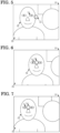
- FIG. 5 somewhat schematically shows screen 12 from the perspective of user 22 in FIG. 1 .
- screen 12 is displaying a display image 70 that includes a face 72.
- eyes 74 of face 72 are not aligned with camera 14, which is not visible behind screen 12.
- Face detection system 18 can locate face 72 and recognize that eyes 74 are not aligned with camera 14. Without eye to camera alignment, the video conferencing system may not promote socially acceptable eye contact.
- Face detection system 18 can promote socially acceptable eye contact by aligning eyes 74 with camera 14.
- FIG. 6 schematically shows the face detection system shifting display image 70 down and to the right so that eyes 74 are aligned with camera 14. In this way, a user that looks directly at eyes 74 will also look directly at camera 14.
- a display image can be shifted by panning the image, stretching one edge of the image while contracting an opposite edge of the image, or through virtually any other suitable technique.
- FIG. 7 schematically shows the face detection system shifting camera 14 up and to the left so that eyes 74 are aligned with camera 14.
- the camera may be mounted on a tracking device that allows the face detection system to reposition the camera.
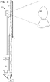
- FIG. 8 shows another embodiment of a video conferencing system 80 that provides gaze accurate video conferencing.
- Video conferencing system 80 includes a screen 82, a camera 84, a projector 86, a face detection system 88, and a sync system 90, similar to those described above with reference to FIG. 1 .
- Video conferencing system 80 also includes a waveguide 92 having an input edge 94 and a viewing surface 96. The waveguide is configured to receive a display image at the input edge and output the display image from the viewing surface.
- projector 86 is positioned to project the display image into the input edge, through the waveguide, and out of the viewing surface.
- At least a portion of a display image projected into the waveguide totally internally reflects upon reaching the interface between the waveguide and air. With each reflection, the direction of the light making up the display image changes with respect to the reflecting surface of the waveguide. Repeated reflections cause the light that makes up the display image to become less susceptible to total internal reflection until the light eventually emerges out viewing surface 96.
- the number of reflections that will occur before the light exits the viewing surface is proportional to the position on the viewing surface from which the light will exit. Therefore, the angle at which light is projected into the input edge can be modulated to control at which position it will exit the viewing surface. In this way, light entering input edge 94 can be controlled so as to exit viewing surface 96 at a desired position, and the waveguide can effectively be used to enlarge the display image in a device having a thin profile.
- Screen 82 can be sized and positioned to substantially cover the viewing surface of the waveguide.
- Sync system 90 can be used to control screen 82, camera 84, and projector 86 as described above with reference to FIG. 2 .
- camera 84 may be positioned to view a camera image that passes into viewing surface 96 and out a backside 98 of the waveguide.
- a camera 100 may be positioned to view a camera image traveling into viewing surface 96, through waveguide 92 and out through input edge 94.
- Such a camera may be offset relative to projector 86.
- a projector may be positioned to project directly into input edge 94, while in other embodiments the projector may be positioned to project into one or more mirrors that redirect projected light into the input edge.
- the waveguide itself may include one or more folds or bends that decrease its overall length.
- a clear protective screen may be added to the above described embodiments so as to help protect the screen that alternates between the light-scattering state and the substantially transparent state.
- a polarizer and/or prismatic turning film may be used to condition light for better display and/or image capture.
- the above described video conferencing systems can include a camera-based touch-detection system that images a screen during its light-scattering state to detect fingers or other objects touching the screen, so that such touches can be recognized as a form of user input.
- touch detection systems may utilize infrared light and/or infrared cameras to monitor touch inputs.
- the above described video conferencing systems are compatible with virtually any projection-based display.
- the above described video conferencing systems are compatible with the design of commercially available projection televisions, surface computers, and other devices.
- programs include routines, objects, components, data structures, and the like that perform particular tasks or implement particular abstract data types.
- program may connote a single program or multiple programs acting in concert, and may be used to denote applications, services, or any other type or class of program.
- computer and “computing device” as used herein include any device that electronically executes one or more programs, including two or more such devices acting in concert.
Landscapes
- Engineering & Computer Science (AREA)
- Multimedia (AREA)
- Signal Processing (AREA)
- Two-Way Televisions, Distribution Of Moving Picture Or The Like (AREA)
- Controls And Circuits For Display Device (AREA)
Claims (7)
- Système de vidéoconférence (80) comprenant :un guide d'onde (92) présentant un bord d'entrée (94) et une surface de visualisation (96), le guide d'onde étant configuré pour recevoir une image d'affichage au niveau du bord d'entrée et délivrer en sortie l'image d'affichage à partir de la surface de visualisation ;un projecteur (86) positionné pour projeter l'image d'affichage dans le bord d'entrée, à travers le guide d'onde, et hors de la surface de visualisation ;une caméra (84) positionnée pour visionner une image de caméra se déplaçant dans la surface de visualisation et à travers le guide d'onde ;un écran (82) couvrant sensiblement la surface de visualisation du guide d'onde et configuré pour commuter sélectivement entre un état sensiblement transparent et un état de diffusion de lumière, dans lequel l'écran inclut un obturateur optique à cristaux liquides texturés cholestériques stabilisés par polymère ; etun système de synchronisation (90) configuré pour amener l'écran à alterner entre l'état sensiblement transparent et l'état de diffusion de lumière, configuré pour amener la caméra à visionner l'image de caméra alors que l'écran est dans l'état sensiblement transparent, et configuré pour amener le projecteur à projeter l'image d'affichage dans le bord d'entrée alors que l'écran est dans l'état de diffusion de lumière,dans lequel le système de synchronisation est configuré pour ajuster dynamiquement un rapport entre un temps pendant lequel l'écran est dans l'état transparent et un temps pendant lequel l'écran est dans l'état de diffusion de lumière en réponse à des variations d'une luminosité ambiante,comprenant en outre un système de détection de visage configuré pour localiser un visage dans l'image d'affichage et aligner les yeux du visage avec la caméra, dans lequel une position et une orientation de la caméra sont alignées avec les yeux d'un visage affiché sur l'écran, de manière que la caméra ait la même vision que les yeux du visage qui est affiché, dans lequel l'axe optique de la caméra est perpendiculaire à une surface de visualisation de l'écran et dans lequel l'axe optique de la caméra coupe l'écran en un point positionné entre les yeux du visage, dans lequel la caméra est déplacée pour aligner les yeux du visage avec la caméra.
- Système de vidéoconférence selon la revendication 1, dans lequel le projecteur inclut une ou plusieurs sources de lumière de projecteur configurées pour une modulation trame-temps entre un état activé et un état désactivé, et le système de synchronisation est configuré pour amener les sources de lumière de projecteur à être dans l'état activé alors que l'écran est dans l'état de diffusion de lumière.
- Système de vidéoconférence selon la revendication 1, dans lequel un axe optique du projecteur est généralement parallèle à la surface de visualisation ; ou
généralement perpendiculaire à la surface de visualisation. - Système de vidéoconférence selon la revendication 1, dans lequel le système de synchronisation inclut un obturateur à cristaux liquides ferroélectriques qui empêche l'image d'affichage d'atteindre l'écran quand l'écran est dans l'état sensiblement transparent.
- Système de vidéoconférence (10) comprenant :un écran (12) pouvant être commuté sélectivement entre un état sensiblement transparent et un état de diffusion de lumière, dans lequel l'écran inclut un obturateur optique à cristaux liquides texturés cholestériques stabilisés par polymère ;une caméra (14) positionnée pour visionner une image de caméra se déplaçant dans l'écran ;un projecteur (16) positionné pour projeter une image d'affichage au niveau de l'écran ;un système de détection de visage (18) pour localiser un visage dans l'image d'affichage et aligner les yeux du visage avec la caméra, dans lequel une position et une orientation de la caméra sont alignées avec les yeux d'un visage affiché sur l'écran, de manière que la caméra ait la même vision que les yeux du visage qui est affiché, dans lequel l'axe optique de la caméra est perpendiculaire à une surface de visualisation de l'écran et dans lequel l'axe optique de la caméra coupe l'écran en un point positionné entre les yeux du visage, dans lequel la caméra est déplacée pour aligner les yeux du visage avec la caméra ; etun système de synchronisation (20) configuré pour amener l'écran à alterner entre l'état sensiblement transparent et l'état de diffusion de lumière, configuré pour amener la caméra à visionner l'image de caméra alors que l'écran est dans l'état sensiblement transparent, et configuré pour amener le projecteur à projeter l'image d'affichage alors que l'écran est dans l'état de diffusion de lumière,dans lequel le système de synchronisation est configuré pour ajuster dynamiquement un rapport entre un temps pendant lequel l'écran est dans l'état transparent et un temps pendant lequel l'écran est dans l'état de diffusion de lumière en réponse à une luminosité ambiante.
- Système de vidéoconférence selon la revendication 5, dans lequel le projecteur inclut une ou plusieurs sources de lumière de projecteur configurées pour une modulation trame-temps entre un état activé et un état désactivé, et le système de synchronisation est configuré pour amener les sources de lumière de projecteur à être dans l'état activé alors que l'écran est dans l'état de diffusion de lumière.
- Système de vidéoconférence (10) selon la revendication 5, dans lequel le projecteur (16) inclut une ou plusieurs sources de lumière de projecteur configurées pour une modulation trame-temps entre un état activé et un état désactivé, le projecteur étant configuré pour projeter une image d'affichage au niveau de l'écran seulement quand les sources de lumière de projecteur sont dans l'état activé.
Applications Claiming Priority (2)
| Application Number | Priority Date | Filing Date | Title |
|---|---|---|---|
| US12/118,754 US8643691B2 (en) | 2008-05-12 | 2008-05-12 | Gaze accurate video conferencing |
| PCT/US2009/040292 WO2009139995A2 (fr) | 2008-05-12 | 2009-04-12 | Visioconférence à regard précis |
Publications (3)
| Publication Number | Publication Date |
|---|---|
| EP2286586A2 EP2286586A2 (fr) | 2011-02-23 |
| EP2286586A4 EP2286586A4 (fr) | 2013-11-06 |
| EP2286586B1 true EP2286586B1 (fr) | 2023-02-22 |
Family
ID=41266523
Family Applications (1)
| Application Number | Title | Priority Date | Filing Date |
|---|---|---|---|
| EP09747081.9A Active EP2286586B1 (fr) | 2008-05-12 | 2009-04-12 | Visioconférence à regard précis |
Country Status (6)
| Country | Link |
|---|---|
| US (1) | US8643691B2 (fr) |
| EP (1) | EP2286586B1 (fr) |
| JP (1) | JP2011520400A (fr) |
| KR (1) | KR101532464B1 (fr) |
| TW (1) | TWI527461B (fr) |
| WO (1) | WO2009139995A2 (fr) |
Families Citing this family (123)
| Publication number | Priority date | Publication date | Assignee | Title |
|---|---|---|---|---|
| US11317057B2 (en) * | 2006-03-18 | 2022-04-26 | Steve H MCNELLEY | Advanced telepresence environments |
| GB0718706D0 (en) | 2007-09-25 | 2007-11-07 | Creative Physics Ltd | Method and apparatus for reducing laser speckle |
| US8593503B2 (en) * | 2008-09-25 | 2013-11-26 | Alcatel Lucent | Videoconferencing terminal and method of operation thereof to maintain eye contact |
| JP2010157854A (ja) * | 2008-12-26 | 2010-07-15 | Sony Corp | 情報処理装置、情報処理方法およびプログラム |
| US11726332B2 (en) | 2009-04-27 | 2023-08-15 | Digilens Inc. | Diffractive projection apparatus |
| US9335604B2 (en) | 2013-12-11 | 2016-05-10 | Milan Momcilo Popovich | Holographic waveguide display |
| US8203595B2 (en) * | 2009-05-21 | 2012-06-19 | Alcatel Lucent | Method and apparatus for enabling improved eye contact in video teleconferencing applications |
| US11320571B2 (en) | 2012-11-16 | 2022-05-03 | Rockwell Collins, Inc. | Transparent waveguide display providing upper and lower fields of view with uniform light extraction |
| US11300795B1 (en) | 2009-09-30 | 2022-04-12 | Digilens Inc. | Systems for and methods of using fold gratings coordinated with output couplers for dual axis expansion |
| US10795160B1 (en) | 2014-09-25 | 2020-10-06 | Rockwell Collins, Inc. | Systems for and methods of using fold gratings for dual axis expansion |
| US8233204B1 (en) | 2009-09-30 | 2012-07-31 | Rockwell Collins, Inc. | Optical displays |
| US8384760B2 (en) * | 2009-10-29 | 2013-02-26 | Hewlett-Packard Development Company, L.P. | Systems for establishing eye contact through a display |
| US9350940B1 (en) * | 2009-10-29 | 2016-05-24 | Hewlett-Packard Development Company, L.P. | Privacy control for a visual-collaborative system |
| WO2011071700A2 (fr) * | 2009-12-07 | 2011-06-16 | Alcatel-Lucent Usa Inc. | Terminal d'imagerie |
| US20110134205A1 (en) * | 2009-12-08 | 2011-06-09 | Susanne Arney | Imaging terminal |
| US8520051B2 (en) * | 2009-12-17 | 2013-08-27 | Alcatel Lucent | Videoconferencing terminal with a persistence of vision display and a method of operation thereof to maintain eye contact |
| US8659826B1 (en) | 2010-02-04 | 2014-02-25 | Rockwell Collins, Inc. | Worn display system and method without requiring real time tracking for boresight precision |
| US8908008B2 (en) * | 2010-07-16 | 2014-12-09 | Hewlett-Packard Development Company, L.P. | Methods and systems for establishing eye contact and accurate gaze in remote collaboration |
| US8988489B2 (en) | 2010-09-15 | 2015-03-24 | Hewlett-Packard Development Company, L. P. | Determining a synchronization relationship |
| US8878894B2 (en) | 2010-09-15 | 2014-11-04 | Hewlett-Packard Development Company, L.P. | Estimating video cross-talk |
| US8692865B2 (en) | 2010-09-15 | 2014-04-08 | Hewlett-Packard Development Company, L.P. | Reducing video cross-talk in a visual-collaborative system |
| US8682030B2 (en) | 2010-09-24 | 2014-03-25 | Microsoft Corporation | Interactive display |
| KR101781533B1 (ko) * | 2010-12-23 | 2017-09-27 | 삼성디스플레이 주식회사 | 영상 촬영 장치 및 이의 영상 촬영 방법 |
| EP2692133B1 (fr) * | 2011-03-31 | 2019-01-16 | SMART Technologies ULC | Dispositif d'affichage de vidéoconférence |
| US20120257004A1 (en) * | 2011-04-05 | 2012-10-11 | Polycom, Inc. | Direct Eye-Contact Enhancing Videoconferencing Unit |
| US9274349B2 (en) | 2011-04-07 | 2016-03-01 | Digilens Inc. | Laser despeckler based on angular diversity |
| US8698940B2 (en) * | 2011-05-09 | 2014-04-15 | Intellectual Ventures Fund 83 Llc | Switchable imaging apparatus for viewing and capture |
| US8446514B2 (en) * | 2011-05-09 | 2013-05-21 | Intellectual Ventures Fund 83 Llc | Capturing images using a switchable imaging apparatus |
| US20120287323A1 (en) * | 2011-05-09 | 2012-11-15 | John Norvold Border | Imaging apparatus with dual switchable beam deflectors |
| US8698941B2 (en) * | 2011-05-09 | 2014-04-15 | Intellectual Ventures Fund 83 Llc | Imaging apparatus with switchable beam deflector array |
| US8610814B2 (en) * | 2011-05-09 | 2013-12-17 | Intellectual Ventures Fund 83 Llc | Switchable imaging apparatus for display and capture |
| US9160966B2 (en) * | 2011-05-11 | 2015-10-13 | Microsoft Technology Licensing, Llc | Imaging through a display screen |
| WO2013006170A1 (fr) * | 2011-07-06 | 2013-01-10 | Hewlett-Packard Development Company, L.P. | Système de portail de téléprésence |
| EP2748670B1 (fr) | 2011-08-24 | 2015-11-18 | Rockwell Collins, Inc. | Affichage de données portable |
| WO2016020630A2 (fr) | 2014-08-08 | 2016-02-11 | Milan Momcilo Popovich | Illuminateur laser en guide d'ondes comprenant un dispositif de déchatoiement |
| US10670876B2 (en) | 2011-08-24 | 2020-06-02 | Digilens Inc. | Waveguide laser illuminator incorporating a despeckler |
| US8634139B1 (en) | 2011-09-30 | 2014-01-21 | Rockwell Collins, Inc. | System for and method of catadioptric collimation in a compact head up display (HUD) |
| US9715067B1 (en) | 2011-09-30 | 2017-07-25 | Rockwell Collins, Inc. | Ultra-compact HUD utilizing waveguide pupil expander with surface relief gratings in high refractive index materials |
| US9366864B1 (en) | 2011-09-30 | 2016-06-14 | Rockwell Collins, Inc. | System for and method of displaying information without need for a combiner alignment detector |
| US9507150B1 (en) | 2011-09-30 | 2016-11-29 | Rockwell Collins, Inc. | Head up display (HUD) using a bent waveguide assembly |
| US8970655B2 (en) * | 2011-12-16 | 2015-03-03 | Polycom, Inc. | Reflective and refractive solutions to providing direct eye contact videoconferencing |
| US20150010265A1 (en) | 2012-01-06 | 2015-01-08 | Milan, Momcilo POPOVICH | Contact image sensor using switchable bragg gratings |
| KR101864452B1 (ko) * | 2012-01-12 | 2018-06-04 | 삼성전자주식회사 | 이미지 촬영 및 화상 통화 장치와 방법 |
| US9523852B1 (en) | 2012-03-28 | 2016-12-20 | Rockwell Collins, Inc. | Micro collimator system and method for a head up display (HUD) |
| EP2842003B1 (fr) | 2012-04-25 | 2019-02-27 | Rockwell Collins, Inc. | Affichage grand angle holographique |
| US8804321B2 (en) | 2012-05-25 | 2014-08-12 | Steelcase, Inc. | Work and videoconference assembly |
| JP5781017B2 (ja) * | 2012-06-05 | 2015-09-16 | 日本電信電話株式会社 | 映像会話システム |
| US8902281B2 (en) | 2012-06-29 | 2014-12-02 | Alcatel Lucent | System and method for image stabilization in videoconferencing |
| US9933684B2 (en) | 2012-11-16 | 2018-04-03 | Rockwell Collins, Inc. | Transparent waveguide display providing upper and lower fields of view having a specific light output aperture configuration |
| US9674413B1 (en) | 2013-04-17 | 2017-06-06 | Rockwell Collins, Inc. | Vision system and method having improved performance and solar mitigation |
| JP6077391B2 (ja) * | 2013-06-06 | 2017-02-08 | パナソニック インテレクチュアル プロパティ コーポレーション オブ アメリカPanasonic Intellectual Property Corporation of America | 撮像表示装置 |
| US9113036B2 (en) * | 2013-07-17 | 2015-08-18 | Ebay Inc. | Methods, systems, and apparatus for providing video communications |
| US9727772B2 (en) | 2013-07-31 | 2017-08-08 | Digilens, Inc. | Method and apparatus for contact image sensing |
| KR101462351B1 (ko) * | 2013-08-16 | 2014-11-14 | 영남대학교 산학협력단 | 시선일치 영상통화장치 |
| US9244281B1 (en) | 2013-09-26 | 2016-01-26 | Rockwell Collins, Inc. | Display system and method using a detached combiner |
| US10732407B1 (en) | 2014-01-10 | 2020-08-04 | Rockwell Collins, Inc. | Near eye head up display system and method with fixed combiner |
| US9519089B1 (en) | 2014-01-30 | 2016-12-13 | Rockwell Collins, Inc. | High performance volume phase gratings |
| US9653044B2 (en) | 2014-02-14 | 2017-05-16 | Microsoft Technology Licensing, Llc | Interactive display system |
| US9244280B1 (en) | 2014-03-25 | 2016-01-26 | Rockwell Collins, Inc. | Near eye display system and method for display enhancement or redundancy |
| CN105306853A (zh) * | 2014-07-31 | 2016-02-03 | 联想(北京)有限公司 | 图像采集设备、投影交互系统及其控制方法 |
| WO2016020632A1 (fr) | 2014-08-08 | 2016-02-11 | Milan Momcilo Popovich | Procédé pour gravure par pressage et réplication holographique |
| US20170285874A1 (en) * | 2014-09-08 | 2017-10-05 | Hewlett-Packard Development Company, L.P. | Capture and projection of an object image |
| WO2016042283A1 (fr) | 2014-09-19 | 2016-03-24 | Milan Momcilo Popovich | Procédé et appareil de production d'images d'entrée pour affichages à guides d'ondes holographiques |
| US10088675B1 (en) | 2015-05-18 | 2018-10-02 | Rockwell Collins, Inc. | Turning light pipe for a pupil expansion system and method |
| US9715110B1 (en) | 2014-09-25 | 2017-07-25 | Rockwell Collins, Inc. | Automotive head up display (HUD) |
| US10437064B2 (en) | 2015-01-12 | 2019-10-08 | Digilens Inc. | Environmentally isolated waveguide display |
| US9632226B2 (en) | 2015-02-12 | 2017-04-25 | Digilens Inc. | Waveguide grating device |
| US11366316B2 (en) | 2015-05-18 | 2022-06-21 | Rockwell Collins, Inc. | Head up display (HUD) using a light pipe |
| US10247943B1 (en) | 2015-05-18 | 2019-04-02 | Rockwell Collins, Inc. | Head up display (HUD) using a light pipe |
| US10126552B2 (en) | 2015-05-18 | 2018-11-13 | Rockwell Collins, Inc. | Micro collimator system and method for a head up display (HUD) |
| CN104917993A (zh) * | 2015-05-29 | 2015-09-16 | 京东方科技集团股份有限公司 | 显示装置及视频通讯终端 |
| US9894259B2 (en) * | 2015-06-29 | 2018-02-13 | Lenovo Enterprise Solutions (Singapore) Pte. Ltd. | Movable image capture devices and methods for capture of images from behind a display screen |
| US10108010B2 (en) | 2015-06-29 | 2018-10-23 | Rockwell Collins, Inc. | System for and method of integrating head up displays and head down displays |
| JP6547480B2 (ja) * | 2015-07-17 | 2019-07-24 | 株式会社リコー | 画像投影装置及び画像投影方法 |
| WO2017060665A1 (fr) | 2015-10-05 | 2017-04-13 | Milan Momcilo Popovich | Afficheur à guide d'ondes |
| CN106921818A (zh) * | 2015-12-24 | 2017-07-04 | 深圳市维海德技术股份有限公司 | 一种视频通讯终端、方法及系统 |
| US10598932B1 (en) | 2016-01-06 | 2020-03-24 | Rockwell Collins, Inc. | Head up display for integrating views of conformally mapped symbols and a fixed image source |
| JP6895451B2 (ja) | 2016-03-24 | 2021-06-30 | ディジレンズ インコーポレイテッド | 偏光選択ホログラフィー導波管デバイスを提供するための方法および装置 |
| EP3433658B1 (fr) | 2016-04-11 | 2023-08-09 | DigiLens, Inc. | Dispositif guide d'onde pour la projection de lumiere structuree |
| CA2963108A1 (fr) * | 2016-06-29 | 2017-12-29 | EyesMatch Ltd. | Systeme et methode destines a un miroir de maquillage numerique |
| JP6782426B2 (ja) * | 2016-08-04 | 2020-11-11 | 株式会社Nttドコモ | 映像提示システム |
| EP3548939A4 (fr) | 2016-12-02 | 2020-11-25 | DigiLens Inc. | Dispositif de guide d'ondes à éclairage de sortie uniforme |
| US10545346B2 (en) | 2017-01-05 | 2020-01-28 | Digilens Inc. | Wearable heads up displays |
| US10295824B2 (en) | 2017-01-26 | 2019-05-21 | Rockwell Collins, Inc. | Head up display with an angled light pipe |
| CN110300950B (zh) | 2017-02-06 | 2023-06-16 | 平蛙实验室股份公司 | 触摸感测系统中的光学耦合 |
| CN111052058B (zh) | 2017-09-01 | 2023-10-20 | 平蛙实验室股份公司 | 改进的光学部件 |
| CN111386495B (zh) | 2017-10-16 | 2022-12-09 | 迪吉伦斯公司 | 用于倍增像素化显示器的图像分辨率的系统和方法 |
| JP7456929B2 (ja) | 2018-01-08 | 2024-03-27 | ディジレンズ インコーポレイテッド | 導波管セルを製造するためのシステムおよび方法 |
| CN114721242B (zh) | 2018-01-08 | 2025-08-15 | 迪吉伦斯公司 | 用于制造光学波导的方法 |
| WO2019136476A1 (fr) | 2018-01-08 | 2019-07-11 | Digilens, Inc. | Architectures de guides d'ondes et procédés de fabrication associés |
| JP7404243B2 (ja) | 2018-01-08 | 2023-12-25 | ディジレンズ インコーポレイテッド | 導波管セル内のホログラフィック格子の高スループット記録のためのシステムおよび方法 |
| US11567610B2 (en) | 2018-03-05 | 2023-01-31 | Flatfrog Laboratories Ab | Detection line broadening |
| CN110324554B (zh) | 2018-03-28 | 2021-08-13 | 北京富纳特创新科技有限公司 | 视频通信装置及方法 |
| CN110324553B (zh) * | 2018-03-28 | 2021-02-26 | 北京富纳特创新科技有限公司 | 基于视频通信的实景窗系统 |
| CN110324559B (zh) | 2018-03-28 | 2021-11-30 | 北京富纳特创新科技有限公司 | 视频通信装置及方法 |
| CN110324555B (zh) | 2018-03-28 | 2021-02-26 | 北京富纳特创新科技有限公司 | 视频通信装置及方法 |
| CN110324556B (zh) | 2018-03-28 | 2023-01-31 | 北京富纳特创新科技有限公司 | 视频通信装置及方法 |
| US10965921B2 (en) * | 2018-06-04 | 2021-03-30 | Guangdong Oppo Mobile Telecommunications Corp., Ltd. | Storage medium, electronic device and image processing method |
| US11402801B2 (en) | 2018-07-25 | 2022-08-02 | Digilens Inc. | Systems and methods for fabricating a multilayer optical structure |
| CN108965771B (zh) * | 2018-09-29 | 2021-01-26 | 京东方科技集团股份有限公司 | 一种视频通话控制装置及方法、视频通话系统 |
| CN112889016A (zh) | 2018-10-20 | 2021-06-01 | 平蛙实验室股份公司 | 用于触摸敏感装置的框架及其工具 |
| WO2020149956A1 (fr) | 2019-01-14 | 2020-07-23 | Digilens Inc. | Affichage de guide d'ondes holographique avec couche de commande de lumière |
| WO2020153890A1 (fr) | 2019-01-25 | 2020-07-30 | Flatfrog Laboratories Ab | Terminal de visioconférence son procédé de fonctionnement |
| US20200247017A1 (en) | 2019-02-05 | 2020-08-06 | Digilens Inc. | Methods for Compensating for Optical Surface Nonuniformity |
| EP3924759B1 (fr) | 2019-02-15 | 2025-07-30 | Digilens Inc. | Procédés et appareils pour fournir un affichage de guide d'ondes holographique à l'aide de réseaux intégrés |
| US20220283377A1 (en) | 2019-02-15 | 2022-09-08 | Digilens Inc. | Wide Angle Waveguide Display |
| JP2022525165A (ja) | 2019-03-12 | 2022-05-11 | ディジレンズ インコーポレイテッド | ホログラフィック導波管バックライトおよび関連する製造方法 |
| EP3980825A4 (fr) | 2019-06-07 | 2023-05-03 | Digilens Inc. | Guides d'ondes incorporant des réseaux transparents et réfléchissants et procédés de fabrication associés |
| JP2022543571A (ja) | 2019-07-29 | 2022-10-13 | ディジレンズ インコーポレイテッド | 画素化されたディスプレイの画像解像度および視野を乗算するための方法および装置 |
| JP2022546413A (ja) | 2019-08-29 | 2022-11-04 | ディジレンズ インコーポレイテッド | 真空回折格子および製造方法 |
| EP4066089B1 (fr) | 2019-11-25 | 2024-09-25 | FlatFrog Laboratories AB | Un appareil de détection tactile |
| JP7316664B2 (ja) * | 2020-02-03 | 2023-07-28 | マルコムホールディングス株式会社 | 対話ユーザの感情情報の提供装置 |
| WO2021158164A1 (fr) | 2020-02-08 | 2021-08-12 | Flatfrog Laboratories Ab | Appareil tactile à interactions à faible latence |
| CN115039063B (zh) | 2020-02-10 | 2026-02-13 | 平蛙实验室股份公司 | 改进的触摸感测设备 |
| WO2022150841A1 (fr) | 2021-01-07 | 2022-07-14 | Digilens Inc. | Structures de réseau pour guides d'ondes de couleur |
| KR20230153459A (ko) | 2021-03-05 | 2023-11-06 | 디지렌즈 인코포레이티드. | 진공 주기적 구조체 및 제조 방법 |
| KR20220128726A (ko) | 2021-03-15 | 2022-09-22 | 삼성전자주식회사 | 머리 착용형 디스플레이 장치, 그 장치에서의 동작 방법 및 저장매체 |
| JP7707104B2 (ja) * | 2022-02-28 | 2025-07-14 | 株式会社ジャパンディスプレイ | 電子機器 |
| JPWO2023170929A1 (fr) * | 2022-03-11 | 2023-09-14 | ||
| JP7505518B2 (ja) * | 2022-03-18 | 2024-06-25 | セイコーエプソン株式会社 | 表示方法、表示システムおよびプログラム |
| JP7459890B2 (ja) | 2022-03-23 | 2024-04-02 | セイコーエプソン株式会社 | 表示方法、表示システムおよびプログラム |
| JP7793485B2 (ja) * | 2022-06-21 | 2026-01-05 | 株式会社ジャパンディスプレイ | 電子機器 |
| US20250220137A1 (en) * | 2024-01-03 | 2025-07-03 | Veeo Technology Inc. | Video conferencing transparent monitor with an integrated behind-display camera |
Family Cites Families (24)
| Publication number | Priority date | Publication date | Assignee | Title |
|---|---|---|---|---|
| JPH06269002A (ja) | 1993-03-10 | 1994-09-22 | Nippon Telegr & Teleph Corp <Ntt> | 表示撮像装置 |
| US5400069A (en) * | 1993-06-16 | 1995-03-21 | Bell Communications Research, Inc. | Eye contact video-conferencing system and screen |
| US5438357A (en) * | 1993-11-23 | 1995-08-01 | Mcnelley; Steve H. | Image manipulating teleconferencing system |
| US5572248A (en) * | 1994-09-19 | 1996-11-05 | Teleport Corporation | Teleconferencing method and system for providing face-to-face, non-animated teleconference environment |
| US5801758A (en) * | 1995-06-21 | 1998-09-01 | Apple Computer, Inc. | System and method for image capture and display utilizing time sharing across a single, two-way optical path |
| US5675376A (en) * | 1995-12-21 | 1997-10-07 | Lucent Technologies Inc. | Method for achieving eye-to-eye contact in a video-conferencing system |
| JP2000298253A (ja) | 1999-04-14 | 2000-10-24 | Seiko Epson Corp | 撮像機能付き液晶表示装置、コンピュータ、テレビジョン電話およびディジタルカメラ |
| US7420585B2 (en) * | 1999-11-30 | 2008-09-02 | Eastman Kodak Company | Image capture and display device |
| GB2360603A (en) | 2000-03-20 | 2001-09-26 | Cambridge 3D Display Ltd | Planar optical waveguide and float glass process |
| GB0028800D0 (en) * | 2000-11-25 | 2001-01-10 | Cambridge 3D Display Ltd | Achromatic flat panel display |
| GB0118866D0 (en) * | 2001-08-02 | 2001-09-26 | Cambridge 3D Display Ltd | Shaped taper flat panel display |
| JP2003150942A (ja) | 2001-11-16 | 2003-05-23 | Kiyomi Nakamura | 目位置追跡方法 |
| US7119829B2 (en) * | 2003-07-31 | 2006-10-10 | Dreamworks Animation Llc | Virtual conference room |
| US20050041286A1 (en) * | 2003-08-18 | 2005-02-24 | White Peter Mcduffie | Front projection screen and systems using same |
| US7285746B2 (en) * | 2004-04-08 | 2007-10-23 | Illinois Tool Works Inc. | Welding gun inlets |
| US8208007B2 (en) * | 2004-04-21 | 2012-06-26 | Telepresence Technologies, Llc | 3-D displays and telepresence systems and methods therefore |
| KR100583516B1 (ko) * | 2004-05-28 | 2006-05-25 | 삼성에스디아이 주식회사 | 광차단막을 구비한 양면 표시 유기 전계발광 디스플레이장치 및 정보 기기 |
| WO2006057475A1 (fr) | 2004-11-23 | 2006-06-01 | Kicheon Hong | Appareil et procede de detection et d'authentification de visage |
| CN100459711C (zh) * | 2005-09-09 | 2009-02-04 | 北京中星微电子有限公司 | 一种视频压缩方法及使用该方法的视频系统 |
| US8022977B2 (en) * | 2005-10-17 | 2011-09-20 | I2Ic Corporation | Camera placed behind a display with a transparent backlight |
| US20070153091A1 (en) * | 2005-12-29 | 2007-07-05 | John Watlington | Methods and apparatus for providing privacy in a communication system |
| KR101240261B1 (ko) * | 2006-02-07 | 2013-03-07 | 엘지전자 주식회사 | 이동통신 단말기의 영상 통화 장치 및 방법 |
| JP2007251778A (ja) * | 2006-03-17 | 2007-09-27 | Saxa Inc | 映像入出力装置 |
| JP5315995B2 (ja) * | 2006-07-14 | 2013-10-16 | 旭硝子株式会社 | 液晶光学素子およびその製造方法 |
-
2008
- 2008-05-12 US US12/118,754 patent/US8643691B2/en not_active Expired - Fee Related
-
2009
- 2009-03-26 TW TW098109952A patent/TWI527461B/zh not_active IP Right Cessation
- 2009-04-12 EP EP09747081.9A patent/EP2286586B1/fr active Active
- 2009-04-12 JP JP2011509518A patent/JP2011520400A/ja not_active Withdrawn
- 2009-04-12 KR KR1020107024951A patent/KR101532464B1/ko not_active Expired - Fee Related
- 2009-04-12 WO PCT/US2009/040292 patent/WO2009139995A2/fr not_active Ceased
Non-Patent Citations (2)
| Title |
|---|
| ASAD KHAN ET AL: "27.4: Super High Brightness Reflective Cholesteric Display", 2001 SID INTERNATIONAL SYMPOSIUM - JUNE 3-8, 2001, SAN JOSE CONVENTION CENTER, CALIFORNIA, vol. XXXII, 3 June 2001 (2001-06-03), pages 460, XP007007693 * |
| SHINICHI SHIWA: "A LARGE-SCREEN VISUAL TELECOMMUNICATIONS DEVICE USING A LIQUID-CRYSTAL SCREEN TO PROVIDE EYE CONTACT", JOURNAL OF THE SOCIETY FOR INFORMATION DISPLAY - SID, SOCIETY FOR INFORMATION DISPLAY, US, vol. 1, no. 1, 1 January 1993 (1993-01-01), pages 37 - 41, XP000510926, ISSN: 1071-0922 * |
Also Published As
| Publication number | Publication date |
|---|---|
| TW200948070A (en) | 2009-11-16 |
| US20090278913A1 (en) | 2009-11-12 |
| EP2286586A2 (fr) | 2011-02-23 |
| KR20110021753A (ko) | 2011-03-04 |
| WO2009139995A3 (fr) | 2010-01-07 |
| US8643691B2 (en) | 2014-02-04 |
| JP2011520400A (ja) | 2011-07-14 |
| WO2009139995A2 (fr) | 2009-11-19 |
| TWI527461B (zh) | 2016-03-21 |
| KR101532464B1 (ko) | 2015-06-29 |
| EP2286586A4 (fr) | 2013-11-06 |
Similar Documents
| Publication | Publication Date | Title |
|---|---|---|
| EP2286586B1 (fr) | Visioconférence à regard précis | |
| US8022977B2 (en) | Camera placed behind a display with a transparent backlight | |
| US7420585B2 (en) | Image capture and display device | |
| US9052414B2 (en) | Virtual image device | |
| US20220100269A1 (en) | Sensor-Based Eye-Tracking Using a Holographic Optical Element | |
| EP3413124A1 (fr) | Détection de la polarisation des lunettes d'un spectateur | |
| WO2021171403A1 (fr) | Dispositif d'affichage vidéo aérien | |
| JP4728793B2 (ja) | ディスプレイ装置およびその制御方法 | |
| KR20190085345A (ko) | 헤드 마운트 장치 | |
| JP5327010B2 (ja) | 表示システム、および表示システムを制御する方法 | |
| JPH0411485A (ja) | 画像表示/撮像装置 | |
| JP3122531B2 (ja) | 表示・撮像装置 | |
| CN119946418A (zh) | 图像信息获取方法、装置、智能眼镜及存储介质 | |
| US20100201606A1 (en) | Frame expanding glasses and frame expanding visual system | |
| CN111399230A (zh) | 一种显示系统及头戴显示设备 | |
| JP3500083B2 (ja) | 眼鏡無し立体映像表示装置 | |
| CN102063007A (zh) | 液晶眼镜、投影显示系统及其控制方法 | |
| JP2021017064A (ja) | ヘッドアップディスプレイ装置 | |
| JP3122543B2 (ja) | 表示・撮像装置 | |
| JP2005275007A (ja) | 撮影装置 | |
| JPH04241591A (ja) | 表示撮像装置 | |
| TW200422765A (en) | Projection system with the capability of projecting two images simultaneously | |
| JP2001021982A (ja) | カメラのファインダ装置 | |
| JP2006337396A (ja) | 携帯情報端末装置 | |
| JP2011109308A (ja) | カメラシステム |
Legal Events
| Date | Code | Title | Description |
|---|---|---|---|
| PUAI | Public reference made under article 153(3) epc to a published international application that has entered the european phase |
Free format text: ORIGINAL CODE: 0009012 |
|
| 17P | Request for examination filed |
Effective date: 20101203 |
|
| AK | Designated contracting states |
Kind code of ref document: A2 Designated state(s): AT BE BG CH CY CZ DE DK EE ES FI FR GB GR HR HU IE IS IT LI LT LU LV MC MK MT NL NO PL PT RO SE SI SK TR |
|
| AX | Request for extension of the european patent |
Extension state: AL BA RS |
|
| DAX | Request for extension of the european patent (deleted) | ||
| A4 | Supplementary search report drawn up and despatched |
Effective date: 20131008 |
|
| RIC1 | Information provided on ipc code assigned before grant |
Ipc: H04N 5/74 20060101ALI20131001BHEP Ipc: H04N 7/14 20060101ALI20131001BHEP Ipc: H04N 7/15 20060101AFI20131001BHEP |
|
| 17Q | First examination report despatched |
Effective date: 20140903 |
|
| RAP1 | Party data changed (applicant data changed or rights of an application transferred) |
Owner name: MICROSOFT TECHNOLOGY LICENSING, LLC |
|
| APBK | Appeal reference recorded |
Free format text: ORIGINAL CODE: EPIDOSNREFNE |
|
| APBN | Date of receipt of notice of appeal recorded |
Free format text: ORIGINAL CODE: EPIDOSNNOA2E |
|
| APBR | Date of receipt of statement of grounds of appeal recorded |
Free format text: ORIGINAL CODE: EPIDOSNNOA3E |
|
| APAF | Appeal reference modified |
Free format text: ORIGINAL CODE: EPIDOSCREFNE |
|
| RAP3 | Party data changed (applicant data changed or rights of an application transferred) |
Owner name: MICROSOFT TECHNOLOGY LICENSING, LLC |
|
| APBT | Appeal procedure closed |
Free format text: ORIGINAL CODE: EPIDOSNNOA9E |
|
| APBD | Information on interlocutory revision deleted |
Free format text: ORIGINAL CODE: EPIDOSDIRAPE |
|
| APBV | Interlocutory revision of appeal recorded |
Free format text: ORIGINAL CODE: EPIDOSNIRAPE |
|
| GRAP | Despatch of communication of intention to grant a patent |
Free format text: ORIGINAL CODE: EPIDOSNIGR1 |
|
| STAA | Information on the status of an ep patent application or granted ep patent |
Free format text: STATUS: GRANT OF PATENT IS INTENDED |
|
| INTG | Intention to grant announced |
Effective date: 20220914 |
|
| GRAS | Grant fee paid |
Free format text: ORIGINAL CODE: EPIDOSNIGR3 |
|
| GRAA | (expected) grant |
Free format text: ORIGINAL CODE: 0009210 |
|
| STAA | Information on the status of an ep patent application or granted ep patent |
Free format text: STATUS: THE PATENT HAS BEEN GRANTED |
|
| AK | Designated contracting states |
Kind code of ref document: B1 Designated state(s): AT BE BG CH CY CZ DE DK EE ES FI FR GB GR HR HU IE IS IT LI LT LU LV MC MK MT NL NO PL PT RO SE SI SK TR |
|
| REG | Reference to a national code |
Ref country code: GB Ref legal event code: FG4D |
|
| REG | Reference to a national code |
Ref country code: CH Ref legal event code: EP |
|
| REG | Reference to a national code |
Ref country code: AT Ref legal event code: REF Ref document number: 1550254 Country of ref document: AT Kind code of ref document: T Effective date: 20230315 Ref country code: IE Ref legal event code: FG4D |
|
| REG | Reference to a national code |
Ref country code: DE Ref legal event code: R096 Ref document number: 602009064756 Country of ref document: DE |
|
| REG | Reference to a national code |
Ref country code: LT Ref legal event code: MG9D |
|
| P01 | Opt-out of the competence of the unified patent court (upc) registered |
Effective date: 20230505 |
|
| REG | Reference to a national code |
Ref country code: AT Ref legal event code: MK05 Ref document number: 1550254 Country of ref document: AT Kind code of ref document: T Effective date: 20230222 |
|
| PG25 | Lapsed in a contracting state [announced via postgrant information from national office to epo] |
Ref country code: PT Free format text: LAPSE BECAUSE OF FAILURE TO SUBMIT A TRANSLATION OF THE DESCRIPTION OR TO PAY THE FEE WITHIN THE PRESCRIBED TIME-LIMIT Effective date: 20230622 Ref country code: NO Free format text: LAPSE BECAUSE OF FAILURE TO SUBMIT A TRANSLATION OF THE DESCRIPTION OR TO PAY THE FEE WITHIN THE PRESCRIBED TIME-LIMIT Effective date: 20230522 Ref country code: NL Free format text: LAPSE BECAUSE OF FAILURE TO SUBMIT A TRANSLATION OF THE DESCRIPTION OR TO PAY THE FEE WITHIN THE PRESCRIBED TIME-LIMIT Effective date: 20230222 Ref country code: LV Free format text: LAPSE BECAUSE OF FAILURE TO SUBMIT A TRANSLATION OF THE DESCRIPTION OR TO PAY THE FEE WITHIN THE PRESCRIBED TIME-LIMIT Effective date: 20230222 Ref country code: LT Free format text: LAPSE BECAUSE OF FAILURE TO SUBMIT A TRANSLATION OF THE DESCRIPTION OR TO PAY THE FEE WITHIN THE PRESCRIBED TIME-LIMIT Effective date: 20230222 Ref country code: HR Free format text: LAPSE BECAUSE OF FAILURE TO SUBMIT A TRANSLATION OF THE DESCRIPTION OR TO PAY THE FEE WITHIN THE PRESCRIBED TIME-LIMIT Effective date: 20230222 Ref country code: ES Free format text: LAPSE BECAUSE OF FAILURE TO SUBMIT A TRANSLATION OF THE DESCRIPTION OR TO PAY THE FEE WITHIN THE PRESCRIBED TIME-LIMIT Effective date: 20230222 Ref country code: AT Free format text: LAPSE BECAUSE OF FAILURE TO SUBMIT A TRANSLATION OF THE DESCRIPTION OR TO PAY THE FEE WITHIN THE PRESCRIBED TIME-LIMIT Effective date: 20230222 |
|
| PG25 | Lapsed in a contracting state [announced via postgrant information from national office to epo] |
Ref country code: SE Free format text: LAPSE BECAUSE OF FAILURE TO SUBMIT A TRANSLATION OF THE DESCRIPTION OR TO PAY THE FEE WITHIN THE PRESCRIBED TIME-LIMIT Effective date: 20230222 Ref country code: PL Free format text: LAPSE BECAUSE OF FAILURE TO SUBMIT A TRANSLATION OF THE DESCRIPTION OR TO PAY THE FEE WITHIN THE PRESCRIBED TIME-LIMIT Effective date: 20230222 Ref country code: IS Free format text: LAPSE BECAUSE OF FAILURE TO SUBMIT A TRANSLATION OF THE DESCRIPTION OR TO PAY THE FEE WITHIN THE PRESCRIBED TIME-LIMIT Effective date: 20230622 Ref country code: GR Free format text: LAPSE BECAUSE OF FAILURE TO SUBMIT A TRANSLATION OF THE DESCRIPTION OR TO PAY THE FEE WITHIN THE PRESCRIBED TIME-LIMIT Effective date: 20230523 Ref country code: FI Free format text: LAPSE BECAUSE OF FAILURE TO SUBMIT A TRANSLATION OF THE DESCRIPTION OR TO PAY THE FEE WITHIN THE PRESCRIBED TIME-LIMIT Effective date: 20230222 |
|
| PG25 | Lapsed in a contracting state [announced via postgrant information from national office to epo] |
Ref country code: RO Free format text: LAPSE BECAUSE OF FAILURE TO SUBMIT A TRANSLATION OF THE DESCRIPTION OR TO PAY THE FEE WITHIN THE PRESCRIBED TIME-LIMIT Effective date: 20230222 Ref country code: EE Free format text: LAPSE BECAUSE OF FAILURE TO SUBMIT A TRANSLATION OF THE DESCRIPTION OR TO PAY THE FEE WITHIN THE PRESCRIBED TIME-LIMIT Effective date: 20230222 Ref country code: DK Free format text: LAPSE BECAUSE OF FAILURE TO SUBMIT A TRANSLATION OF THE DESCRIPTION OR TO PAY THE FEE WITHIN THE PRESCRIBED TIME-LIMIT Effective date: 20230222 Ref country code: CZ Free format text: LAPSE BECAUSE OF FAILURE TO SUBMIT A TRANSLATION OF THE DESCRIPTION OR TO PAY THE FEE WITHIN THE PRESCRIBED TIME-LIMIT Effective date: 20230222 |
|
| REG | Reference to a national code |
Ref country code: DE Ref legal event code: R097 Ref document number: 602009064756 Country of ref document: DE |
|
| PG25 | Lapsed in a contracting state [announced via postgrant information from national office to epo] |
Ref country code: SK Free format text: LAPSE BECAUSE OF FAILURE TO SUBMIT A TRANSLATION OF THE DESCRIPTION OR TO PAY THE FEE WITHIN THE PRESCRIBED TIME-LIMIT Effective date: 20230222 |
|
| REG | Reference to a national code |
Ref country code: CH Ref legal event code: PL |
|
| PG25 | Lapsed in a contracting state [announced via postgrant information from national office to epo] |
Ref country code: LU Free format text: LAPSE BECAUSE OF NON-PAYMENT OF DUE FEES Effective date: 20230412 |
|
| PLBE | No opposition filed within time limit |
Free format text: ORIGINAL CODE: 0009261 |
|
| STAA | Information on the status of an ep patent application or granted ep patent |
Free format text: STATUS: NO OPPOSITION FILED WITHIN TIME LIMIT |
|
| REG | Reference to a national code |
Ref country code: BE Ref legal event code: MM Effective date: 20230430 |
|
| PG25 | Lapsed in a contracting state [announced via postgrant information from national office to epo] |
Ref country code: MC Free format text: LAPSE BECAUSE OF FAILURE TO SUBMIT A TRANSLATION OF THE DESCRIPTION OR TO PAY THE FEE WITHIN THE PRESCRIBED TIME-LIMIT Effective date: 20230222 |
|
| 26N | No opposition filed |
Effective date: 20231123 |
|
| PG25 | Lapsed in a contracting state [announced via postgrant information from national office to epo] |
Ref country code: SI Free format text: LAPSE BECAUSE OF FAILURE TO SUBMIT A TRANSLATION OF THE DESCRIPTION OR TO PAY THE FEE WITHIN THE PRESCRIBED TIME-LIMIT Effective date: 20230222 Ref country code: MC Free format text: LAPSE BECAUSE OF FAILURE TO SUBMIT A TRANSLATION OF THE DESCRIPTION OR TO PAY THE FEE WITHIN THE PRESCRIBED TIME-LIMIT Effective date: 20230222 Ref country code: LI Free format text: LAPSE BECAUSE OF NON-PAYMENT OF DUE FEES Effective date: 20230430 Ref country code: CH Free format text: LAPSE BECAUSE OF NON-PAYMENT OF DUE FEES Effective date: 20230430 |
|
| REG | Reference to a national code |
Ref country code: IE Ref legal event code: MM4A |
|
| PG25 | Lapsed in a contracting state [announced via postgrant information from national office to epo] |
Ref country code: BE Free format text: LAPSE BECAUSE OF NON-PAYMENT OF DUE FEES Effective date: 20230430 |
|
| PG25 | Lapsed in a contracting state [announced via postgrant information from national office to epo] |
Ref country code: IE Free format text: LAPSE BECAUSE OF NON-PAYMENT OF DUE FEES Effective date: 20230412 |
|
| PG25 | Lapsed in a contracting state [announced via postgrant information from national office to epo] |
Ref country code: IE Free format text: LAPSE BECAUSE OF NON-PAYMENT OF DUE FEES Effective date: 20230412 |
|
| PGFP | Annual fee paid to national office [announced via postgrant information from national office to epo] |
Ref country code: GB Payment date: 20240320 Year of fee payment: 16 |
|
| PG25 | Lapsed in a contracting state [announced via postgrant information from national office to epo] |
Ref country code: IT Free format text: LAPSE BECAUSE OF FAILURE TO SUBMIT A TRANSLATION OF THE DESCRIPTION OR TO PAY THE FEE WITHIN THE PRESCRIBED TIME-LIMIT Effective date: 20230222 |
|
| PGFP | Annual fee paid to national office [announced via postgrant information from national office to epo] |
Ref country code: FR Payment date: 20240320 Year of fee payment: 16 |
|
| PGFP | Annual fee paid to national office [announced via postgrant information from national office to epo] |
Ref country code: DE Payment date: 20240320 Year of fee payment: 16 |
|
| PG25 | Lapsed in a contracting state [announced via postgrant information from national office to epo] |
Ref country code: BG Free format text: LAPSE BECAUSE OF FAILURE TO SUBMIT A TRANSLATION OF THE DESCRIPTION OR TO PAY THE FEE WITHIN THE PRESCRIBED TIME-LIMIT Effective date: 20230222 |
|
| PG25 | Lapsed in a contracting state [announced via postgrant information from national office to epo] |
Ref country code: BG Free format text: LAPSE BECAUSE OF FAILURE TO SUBMIT A TRANSLATION OF THE DESCRIPTION OR TO PAY THE FEE WITHIN THE PRESCRIBED TIME-LIMIT Effective date: 20230222 |
|
| PG25 | Lapsed in a contracting state [announced via postgrant information from national office to epo] |
Ref country code: CY Free format text: LAPSE BECAUSE OF FAILURE TO SUBMIT A TRANSLATION OF THE DESCRIPTION OR TO PAY THE FEE WITHIN THE PRESCRIBED TIME-LIMIT; INVALID AB INITIO Effective date: 20090412 |
|
| PG25 | Lapsed in a contracting state [announced via postgrant information from national office to epo] |
Ref country code: HU Free format text: LAPSE BECAUSE OF FAILURE TO SUBMIT A TRANSLATION OF THE DESCRIPTION OR TO PAY THE FEE WITHIN THE PRESCRIBED TIME-LIMIT; INVALID AB INITIO Effective date: 20090412 |
|
| REG | Reference to a national code |
Ref country code: DE Ref legal event code: R119 Ref document number: 602009064756 Country of ref document: DE |
|
| PG25 | Lapsed in a contracting state [announced via postgrant information from national office to epo] |
Ref country code: TR Free format text: LAPSE BECAUSE OF FAILURE TO SUBMIT A TRANSLATION OF THE DESCRIPTION OR TO PAY THE FEE WITHIN THE PRESCRIBED TIME-LIMIT Effective date: 20230222 |
|
| GBPC | Gb: european patent ceased through non-payment of renewal fee |
Effective date: 20250412 |
|
| PG25 | Lapsed in a contracting state [announced via postgrant information from national office to epo] |
Ref country code: DE Free format text: LAPSE BECAUSE OF NON-PAYMENT OF DUE FEES Effective date: 20251104 |
|
| PG25 | Lapsed in a contracting state [announced via postgrant information from national office to epo] |
Ref country code: GB Free format text: LAPSE BECAUSE OF NON-PAYMENT OF DUE FEES Effective date: 20250412 |
|
| PG25 | Lapsed in a contracting state [announced via postgrant information from national office to epo] |
Ref country code: FR Free format text: LAPSE BECAUSE OF NON-PAYMENT OF DUE FEES Effective date: 20250430 |