EP2292444A2 - Dispositif de traitement cyclé d'imprimés à l'aide d'un dispositif de transfert - Google Patents
Dispositif de traitement cyclé d'imprimés à l'aide d'un dispositif de transfert Download PDFInfo
- Publication number
- EP2292444A2 EP2292444A2 EP10173311A EP10173311A EP2292444A2 EP 2292444 A2 EP2292444 A2 EP 2292444A2 EP 10173311 A EP10173311 A EP 10173311A EP 10173311 A EP10173311 A EP 10173311A EP 2292444 A2 EP2292444 A2 EP 2292444A2
- Authority
- EP
- European Patent Office
- Prior art keywords
- book
- transfer
- book block
- translation
- transfer device
- Prior art date
- Legal status (The legal status is an assumption and is not a legal conclusion. Google has not performed a legal analysis and makes no representation as to the accuracy of the status listed.)
- Withdrawn
Links
- 238000012546 transfer Methods 0.000 title claims abstract description 132
- 238000012545 processing Methods 0.000 title claims abstract description 35
- 238000013519 translation Methods 0.000 claims abstract description 34
- 230000033001 locomotion Effects 0.000 claims description 55
- 238000007639 printing Methods 0.000 claims description 9
- 230000001133 acceleration Effects 0.000 claims description 8
- 239000000853 adhesive Substances 0.000 claims description 6
- 230000001070 adhesive effect Effects 0.000 claims description 6
- 239000011230 binding agent Substances 0.000 claims description 6
- 239000007853 buffer solution Substances 0.000 claims description 2
- 230000003247 decreasing effect Effects 0.000 claims description 2
- 230000001419 dependent effect Effects 0.000 claims description 2
- 239000011159 matrix material Substances 0.000 claims description 2
- 235000004522 Pentaglottis sempervirens Nutrition 0.000 claims 1
- 125000004122 cyclic group Chemical group 0.000 claims 1
- 238000007646 gravure printing Methods 0.000 claims 1
- 238000007645 offset printing Methods 0.000 claims 1
- 230000006641 stabilisation Effects 0.000 claims 1
- 238000011105 stabilization Methods 0.000 claims 1
- 230000014616 translation Effects 0.000 description 17
- 230000008901 benefit Effects 0.000 description 13
- 238000000034 method Methods 0.000 description 12
- 230000008569 process Effects 0.000 description 11
- 239000000047 product Substances 0.000 description 9
- 230000007246 mechanism Effects 0.000 description 7
- 230000008859 change Effects 0.000 description 5
- 230000003044 adaptive effect Effects 0.000 description 4
- 230000000694 effects Effects 0.000 description 4
- 238000005259 measurement Methods 0.000 description 4
- 230000009471 action Effects 0.000 description 3
- 238000013461 design Methods 0.000 description 3
- 230000008092 positive effect Effects 0.000 description 3
- 241000196324 Embryophyta Species 0.000 description 2
- 230000002411 adverse Effects 0.000 description 2
- 238000001514 detection method Methods 0.000 description 2
- 238000004519 manufacturing process Methods 0.000 description 2
- 230000002093 peripheral effect Effects 0.000 description 2
- 230000002688 persistence Effects 0.000 description 2
- 230000000087 stabilizing effect Effects 0.000 description 2
- 235000010678 Paulownia tomentosa Nutrition 0.000 description 1
- 240000002834 Paulownia tomentosa Species 0.000 description 1
- 238000009825 accumulation Methods 0.000 description 1
- 238000005452 bending Methods 0.000 description 1
- 229910052793 cadmium Inorganic materials 0.000 description 1
- BDOSMKKIYDKNTQ-UHFFFAOYSA-N cadmium atom Chemical compound [Cd] BDOSMKKIYDKNTQ-UHFFFAOYSA-N 0.000 description 1
- 239000011248 coating agent Substances 0.000 description 1
- 238000000576 coating method Methods 0.000 description 1
- 230000000295 complement effect Effects 0.000 description 1
- 230000001934 delay Effects 0.000 description 1
- 230000003111 delayed effect Effects 0.000 description 1
- 238000011161 development Methods 0.000 description 1
- 230000018109 developmental process Effects 0.000 description 1
- 238000011143 downstream manufacturing Methods 0.000 description 1
- 230000029142 excretion Effects 0.000 description 1
- 239000012467 final product Substances 0.000 description 1
- 230000006872 improvement Effects 0.000 description 1
- 238000009434 installation Methods 0.000 description 1
- 238000012423 maintenance Methods 0.000 description 1
- 238000007726 management method Methods 0.000 description 1
- 210000000056 organ Anatomy 0.000 description 1
- 230000036961 partial effect Effects 0.000 description 1
- 238000000275 quality assurance Methods 0.000 description 1
- 230000009467 reduction Effects 0.000 description 1
- 230000002829 reductive effect Effects 0.000 description 1
- 239000000243 solution Substances 0.000 description 1
- 230000003068 static effect Effects 0.000 description 1
- 238000011144 upstream manufacturing Methods 0.000 description 1
Images




Classifications
-
- B—PERFORMING OPERATIONS; TRANSPORTING
- B42—BOOKBINDING; ALBUMS; FILES; SPECIAL PRINTED MATTER
- B42C—BOOKBINDING
- B42C19/00—Multi-step processes for making books
- B42C19/08—Conveying between operating stations in machines
-
- B—PERFORMING OPERATIONS; TRANSPORTING
- B65—CONVEYING; PACKING; STORING; HANDLING THIN OR FILAMENTARY MATERIAL
- B65H—HANDLING THIN OR FILAMENTARY MATERIAL, e.g. SHEETS, WEBS, CABLES
- B65H2301/00—Handling processes for sheets or webs
- B65H2301/30—Orientation, displacement, position of the handled material
- B65H2301/31—Features of transport path
- B65H2301/312—Features of transport path for transport path involving at least two planes of transport forming an angle between each other
- B65H2301/3121—L-shaped
Definitions
- the present invention relates to a device according to the preamble of claim 1.
- EP 1 645 434 A1 has become known a device for the intermittent processing of book blocks formed from printed sheets, which are often composed of individual sheets or folded signatures.
- the feed member is assigned to a lifting device having the stop.
- a supplied book block is pivoted from a horizontal position to a vertical position, and by means of an adjustable driven stop this book block is transferred to the adhesive tongs of the binder.
- horizontally supplied book blocks can be transferred in a targeted manner and unhindered into an adhesive binder station while avoiding further transfer movements. It is by the lifting device the book block up and introduced from below in an adhesive tweezers.
- This lifting movement is initiated before the arrival of a book block at the stop, wherein the adjustability of the stop can also be used to adjust the format of the supplied book block.
- the cycle time it has been found in such a sequence that the cycle time, respectively.
- Cadmium is subject to a relatively strong limitation, so that an increase in the number of cycles is no longer achievable, because the underlying process is such that each first a return stroke has to be made before a new book block nachschoben, so can be accepted.
- the management level forming guide rails had to be assigned by far a guide, which supports the book block on the opposite side supporting and leading.
- the book blocks can each be pivoted from the lying position on the feed organ into a position vertical to the book block back by a drive-connected countershaft with the stop, this can only be achieved if corresponding additional guide rails are provided.
- the different book block thicknesses against tilting require adjusting the distance between the guide plane formed by the guide rails and the guide element. However, this can be done kinematically only properly if a traction mechanism is provided.
- the guide rails must be located below the slidably supported by support on the supports of the conveyor elements, so that friction of the book block can be avoided on the guide rails , which consequently leads to additional provisions.
- the invention aims to remedy the disadvantages of the prior art remedy and show advantageous new ways.
- the invention as characterized in the claims, the object is to process the book block with a maximized clock frequency in a device of the type mentioned.
- Another object of the invention is to propose provisions to remove the individual book blocks as quickly as possible from the book block feeder by the use of a transfer device, so that space for the next incoming book block is certainly created. This has a positive effect on the cycle times and allows a performance maximization.
- the book blocks are preferably produced with a digital printing press, such a digital printing machine allowing a book block or book to be printed in a sequence. If a book block is printed sequentially, it means that the digital press starts with the first sheet, and the subsequent spreads, which complete the book or book block, are added immediately. Digital printing machines work without a fixed printing form, and therefore can operate in the stated manner. Following the printing process, the sheets can then be stacked either as a single sheet into a book block, or folded into signatures using a suitable folding machine and stacked into book blocks.
- the book blocks which are transferred are preferably loose stacks of signatures and or folded signatures. But they can also be fixed in a way for safe transport, so that the individual sheets and / or signatures can not slip to each other. It may also be understood that such a named fixation is effected with respect to the position of the stacked printed sheets and / or signatures and / or temporarily, and that said fixations in the printed product finished to the final product, or that which is processed with the further processing device, have no system-relevant effect more unfolded. Thus, the compactness of the book block can be ensured during transport.
- the motion profiles can consist of various curve functions and also by dwell times or downtimes resp. be composed. In principle, it is therefore a matter of letting the movement speed follow a certain locomotion profile, which consists of one or more simple curve functions or superimposed one another, both in connection with the transfer process and with respect to the otherwise relevant speeds within the device, in particular also in terms of the movement speeds of the book block feeder and the book channel
- the book block is not fed directly into the pliers, but handed over to an upstream book channel.
- a book channel is known per se to those skilled in the art and is used, for example, in connection with a collating machine.
- Such a book channel is also known as gathering channel in collating machines, which can convey signatures, bound books and loose or fixed book blocks by means of catch fingers or other auxiliary mechanisms in the channel.
- the basic advantage of the invention is to be seen here in that one basically distances from a purely linear or quasi-linear feeding of the book blocks from one station to the next, and now proposes that the book blocks be based on a rotary or quasi-rotary translation be forwarded to the book channel before they are forwarded to a processing station, whereby the clock numbers can be increased sustainably, and at the same time gentle handling of the loose book block.
- translation is understood to mean a movement in which all points of the moving body move in the same direction.
- a quasi-rotary translation is basically understood a movement in which the book block is promoted under an arc-like movement.
- this movement can also be superimposed by at least one linear movement in one axis, or expand or superimpose the rotary movement at any point.
- Such movement can also be accomplished by an external engaging mechanism, such as a robotic arm.
- the linear motion sequence does not necessarily have to be implemented before or after the rotary movement, but it can also be done intermediately. Such combinations are always appropriate where the space or existing aggregates limit the spaces of freedom. It is also advantageous here that this linear movement can take place in a horizontal, vertical or even inclined position, which additionally ensures great flexibility of the device according to the invention.
- the rotational or at least the quasi-rotary translation during the transfer process is not necessarily limited solely to a two-dimensional acting movement, but during the supply, the said translational movements can readily take the third dimension in space as needed, in Considering the fact that the layers of each Falzbogen are to be handled optimally at least during the entire transfer process so that, for example, they can not slip in themselves, so able to maintain their compactness throughout the process assets.
- the rotary or quasi-rotary translations can assume any position per se, ie be horizontal or vertical or inclined, wherein intermediate combinations are also possible.
- Another significant advantage of the invention is the fact that the system is such that both a continuous and an intermittent feeding of the book blocks is possible, which in turn expands the applicability and flexibility of the system resp. increased. This may be necessary, for example, if measurement / control stations are provided in the processing stream which trigger qualitatively induced interventions without the product-related current cadence being adversely affected thereby. However, this does not always apply to conventional linear delivery: quality-induced interventions have a negative effect on product-related cadence.
- Another significant advantage of the invention is the fact that the system includes provisions whose geometry is chosen so that on the feeds an adjustment to the respective format of the book blocks basically unnecessary, which in turn has the advantage that even the smallest lots without the execution of large Umraumen can be processed.
- the system according to the invention behaves flexibly in relation to a strictly tact-related continuous feeding of the buck blocks to the transfer device belonging to the transfer process, it is possible to move in front of the rotary movements readily provide measuring / control stations, which are set to close tolerances, and which respond when exceeding a certain tolerance limit and activate appropriate Ausschleusungsmechanismen.
- the mass controls that are set out herein relate to the format of the book blocks, and are preferably aligned with the height, width, and thickness of the particular block of buckets, and also include a book block-related identification feature.
- the measurement / control stations can also forward measured data to the further processing station, for example, to obtain accurate settings of the subsequent processing machines.
- the measuring / control stations not only take over a mere static check of an actual state, but they pass on production-relevant information to the downstream processing machines.
- Another significant advantage of the invention is the fact that the position of the book block along the book block feeder can be done both transversely and longitudinally, without the cycle numbers would be adversely affected, for example, by making the best possible alignment of the book block before the perfect binder affects the not specified by the translation clock number.
- This high flexibility is causally related to the broad design possibilities of the translations used in the area of the transfer device, ie, the movement of the translation can control the transfer of the book block the book channel so that the subsequent processing processes, such as the attachment of the binder under continuous optimal Conditions can take place.
- the transfer device belonging to takeover element which can be used, for example in the form of a fork-like structure, during translation, the forwarding of the book block takes over, immediately before passing an inclination is subjected, which the book block in the takeover element a obliquely oblique position, so that the book block can slide targeted to a stop within this transfer element.
- Such an inclination causes, inter alia, a stabilizing effect on the mass of the book block, which effect is accompanied by an increase in the persistence of the body.
- this inclination can also be original and does not necessarily have to be created in the course of the process, ie especially in the course of the rotary or quasi-rotary movement, at a suitable location.
- Another important advantage of the system-related invention is the fact that this also gives advantages to the peripheral systems, which are responsible for the product streams.
- printed products can be forwarded from a plurality of product streams or from divided product streams, ie several feed stations can converge to the rotary or quasi-rotary translation of the operating transfer device so that, if required, parallel-operated transfer devices can also be provided.
- the impact is here For example, increased production, which is causally related to increased productivity of the inventive device.
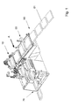
- Fig. 1 shows a plant A, which consists essentially of a supply means 60 for book block 61, an intermediary switched control device 50, a transfer device 10, a conveyor line 70, which the book blocks to a processing station not shown here (see Fig. 7 ) leads.
- the feeding device 60 will be referred to below as the “book block feeder” and the conveying path for the book blocks 70 after the transfer device as the "book channel”.
- Fig. 2 is a stylized representation of Fig. 1 and will show essentially only the main components of this Appendix A, namely the transfer device 10, the book block feeder 60, and the book channel 70. What emerges particularly well from this figure is the acquisition 62 of a book block 61 by a component of the transfer device 10.
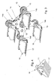
- Fig. 3 shows the detailed structure of the previously mentioned transfer device 10, which forms the central component, between the book block feeder 60 for the book block 61 and the book channel 70, which leads to the other processing stations.
- This main center axis 12 is in operative connection with a known planetary gear 13 which drives along a circular motion a quadrangular star-shaped rotor 14, wherein the four vertices this rotor 14 each carry a standing with a peripheral gear 15 of the planetary gear 13 operatively connected shaft 14a-14d, each of which form the starting point for receiving a transfer element 16, which in turn is console-like, and has a fork-like support plane 17 which the Support surface for the further transport of the book block 61 forms, said support plane 17 is preferably designed for receiving a single book block 61.
- each transfer element 16 together with the support plane 17 initially assumes a preferably quasi-horizontal position over a large part of the circumferential movement.
- the support planes 17 are not strictly in a horizontal position, but they already have an original inclination, which is in accordance with the inclination of the book channel 70.
- the support planes 17 can also have a parallel to the book block feed or horizontal position.
- the respective underlying situation is directly related to an optimal recording and subsequent delivery of the book block 61, so with the course of the book block 60 and the book 70 on the other hand. The goal is therefore here that brought up on the book block feeder 60 book block both gently on the support plane 17 are pushed, and can be passed from the book channel 70 gently.
- the support levels 17 initially retain their once assumed horizontal or quasi-horizontal position. Seen in this way, the circularly rotating transfer elements 16 have a sequence of movements which is similar to that of a ferris wheel equipped with free-floating cabins.
- the book blocks 61 are transported further on the support plane 17 and in the final phase of a cycle they are transferred to the book channel 70.
- this handover should be maximized, which is an essential aspect of quality assurance.
- the dynamics in this transfer can be designed so that the support plane 17 initially occupies an intermediate position above the book channel 70, then to initiate an acceleration in the direction of the book channel 70 from this intermediate position, then in the final phase of the course at decreasing and adapted speed approximates the book channel 70 quasi-symptomatically, thus ensuring the conditions for maximized smooth handover of the book block 61.
- Such an acceleration may e.g. be done gently when accelerating a lying on the intermediate plane driver fingers and conveys the book block in the book channel 70, wherein at product transfer to the book channel relative speed differences are kept low.
- the support plane 17 is delimited by two adjacent walls 18, 19, which are preferably perpendicular to each other. This squareness corresponds to the circumferential geometry of the book block 61, wherein the corner formed by the adjacent walls 18, 19 forms an optimum end stop for the book block 61, as will be discussed in more detail later.
- Fig. 4 shows the structure of a single transfer element 16. This has in the region of the wall 19 a slot 11, the width of which continues over the entire supporting plane 17. A driver finger (see FIGS. 5 and 6 ) is in operative connection with this slot 11, such that a gentle repulsion of the book block 61 from the said supporting plane 17 to the book channel 70 not shown here can take place.
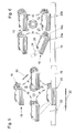
- Fig. 5 shows the transfer device 10 from Fig. 3 in a simplified representation, with the transfer elements 16, which are shown here in the poles. Again, it can be well established that the support plane 17 of each transfer element 16 assumes a quasi-horizontal position, as can be seen from the graphic representation. As further shown, takeover elements 16 rotate counterclockwise 20, and they are operatively connected to a lower side arranged Buchkanal 70, the running direction 12 is opposite to the direction of rotation 20 of the transfer device 10. In the direction of movement of the book channel 70 act fixedly spaced driver fingers 23, which take over the gentle repulsion of the respective book block of the supporting plane 7 of the transfer element 16 to the immediately underlying book channel 70. For this purpose, the transfer element 16 has a continuous slot 11 extending parallel to the running direction of the book channel 70 (see FIG Fig. 4 ), which is tuned to the thickness of the driving finger 23, and which is particularly good Fig. 4 evident.
- the underlying horizontal position of the individual support levels 17 to the underlying book channel 70 undergoes per revolution a time-related change in position, which is initiated by a gate 24, which detects the respective transfer element 16 immediately before reaching the lowermost buchkanal section, and the predominantly searchenden at this point takeover element 16 imposes an angularly changing part movement about the shaft 14c, as is apparent from Fig. 6 is apparent.
- a roller 25 connected to the transfer element 16 ensures that the link 24 is scanned faithfully.
- the introduction of the change in position with respect to the support plane 17 can also be done by a complementary drive element, for example by a motor or cam gear.
- the gate 24 can also be designed so that the respective transfer element 16, in addition to the described angular movement, can additionally assume a movement in an oblique or oblique position, which forms a diagonal to the corner formed by the adjacent walls 18, 19, so that the book block 61 against the right-angled corner of the two walls 18, 19 (see 3 and 4 ) can possibly slip and is caught there position stable.
- the gate 24 may also have a toothed or undulating surface, such that the movement of the supporting plane 17, which is in operative connection with the link 24, is subjected to a vibrating motion.
- the scanned surface may also be configured to transmit vibrations to the support plane 17 during scanning. In both cases, this has a positive effect on the position of the book blocks to be taken.
- this oblique stop position for the book block 61 can also be provided originally, so that this inclination does not have to be additionally introduced via a backdrop or by other auxiliary equipment. In any case, such an inclination triggers a stabilizing effect on the mass of the book block 61, which is associated with an increase in its persistence. This ensured compactness of the book block then has a later positive effect on the passage of the subsequent processing stations.
- the purpose-related inclination of the transfer element 16 by the action of the gate 24 can be replaced by the strategy described above is pursued by the transfer element 16 above the book channel 70 so long holds the height until the respective location-catching driver fingers 23 critical Has passed through the zone.
- the angle-related change in the position of the book block can also be done at any other place. Then another mechanism would be available, e.g. via a motor axis or a cam mechanism in the rotor, which can act superimposed over the ordinary translation of the transfer device.
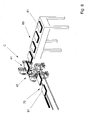
- This transfer device 30 which is functionally arranged to and above the book block feeder 60 and the book channel 70, preferably has a rotating rotor 31 in the poles, and in these poles, a vertically downward clamping device 32 is arranged, each of which a book block 61 of the book block feeder 60 summarizes and preferably brings by a 90 ° angular movement in the plane of the book channel 70. In this plane, the clamping action is then released, so that the book block 61 can be conveyed via the book channel 70 to a further processing station 90.
- the clamping device 32 preferably performs a downward movement 33 in the direction of the book channel 70 during rotation in order to gently place the book block 61 in the book channel 70, whereby here the rotary movement of the rotor 31 is coupled to a linear component.
- FIG. 7 the processing station 90 is only hinted at.
- the transfer device 30 shown here thus operates according to another principle with respect to the previously described transfer device 10 (FIG. Fig. 3-6 ) out. On the execution possibilities of such a clamping device 32 is not entered here.
- the located at the poles clamping devices 32 can maintain the position of the book block with a planetary gear, which in the Fig.1 has been described. But it is also conceivable that if necessary during the 90 ° rotation - which may of course also have a different angular amount, the ancestral position of the book block is additionally rotated by an angular amount, for example by 90 °. This couples two rotary rotations together.
- this system B can be seen in the fact that it is readily possible to vary the number of acting clamping devices 32 and the angular velocity so that they take into account the given circumstances. In most cases, it will be preferable to use a 90 ° clock, ie 90 ° rotation angle. However, a skewed disposition of the transfer device 30 is also possible, and in particular recommended if the pre-entry and / or forwarding of the book block 61 must be made via inclined planes. In all cases, the book block is transferred gently and undergoes no internal bending and the given compactness or shape is maintained.
- the linear translation of the clamping device 32 can act up or down. This also applies to the clamping device in Fig. 8 ,
- FIG. 8 Another plant C goes out Fig. 8 in which a further transfer device 40 is shown.
- this transfer device 40 works in a similar manner to that according to Appendix A (see Fig. 3-6 ), ie, after the conditional by a clamping device 41 detection of the brought-book block 61 sets a rotary motion, which has the same technical characteristics, as already described in Appendix B ( Fig. 7 ) are.
- the transfer of the book block 61 the book channel 70 is here, however, a direct, because the opening of the clamping device 41 is sufficient to ensure the detection and further transport of the book block 61.
- the rotary movement of the transfer device 40 ensures that the book block 61 is transferred from a higher infeed level to a lower transfer level.
- a diametrically opposite configuration is possible in which the book block is transferred from a lower level to a higher level.
- Appendix C can also be designed so that the lowest position of the arms which form the clamping device 41, is equal to the book channel 70. If the direction of rotation of the transfer element is then introduced clockwise, the book block can be deposited in the direction of movement of the driver finger.
- the advantage of such konkondart movement is to be seen in the fact that the relative speed of the book block can be reduced to the driver finger or a stop bar to an optimum, such that the relative speed tends to zero, thus ensuring a safe smooth transfer of the book block is ensured.
- Fig. 8 See also the embodiment, according to which the transfer of the book block the book channel 70 not only at an angle of 90 ° with respect to the acquisition can take place, but is readily possible to provide this transfer even at 180 ° in relation to the transfer point, so diametrically opposed, that is, then, that the book channel 70 acts on the underside of the transfer device 40, which in turn can be operated with an optimized relative speed between the angular speed of the book block and the book speed of the book channel.
- the concordant movements between the direction of rotation of the transfer device and direction of the book channel is discussed in more detail in the previous section.
- the transfer device 80 shown here consists of a scoop-wheel-like inlet star 80, which individually receives the brought-Buck blocks 61 between the space created therefrom 81 and further promotes rotation in the same rotary plane. After a rotation angle of about 90 °, the book block 61 is ejected from the blade wheel-like inlet star 80 and taken from a substantially perpendicular to the book block feeder 60 arranged book channel 70 and passed on for further processing. Another angle of rotation is also possible.
- the structure of this system D is therefore designed so that the book block 61 already present vertically in the book channel 70, which has advantages for further processing, because the book block 61 must then, for example, in an adhesive binder station, no longer specifically transferred to a vertical position.
- transfer devices described In connection with the transfer devices described, it should be emphasized that these are particularly well suited for providing the highest output cadences.
- two or more transfer devices can operate on the same book channel, which can be loaded at full capacity corresponding to book block, and by which the cadence of the expulsion can be multiplied in a subsequent common book channel.
- Fig. 10 shows in a simplified representation the immediate area of a book block feeder 60 after a measuring / control station 50 (see Fig. 1 ), where it comes to a discharge of a book block 61 due to a detected shortage to accomplish.
- a discharge point 95 is provided, which works differently and can come into function.
- this Ausschleusstelle 95 in action by the conveyor belt along the book block guide 60 acts telescopically, ie by a part 91 of the conveyor belt inwardly back, thus freeing the space for the discharge.
- the book block feeder 60 consists of one of a rust-like plane 92, which may be variously constructed.
- the elements of the rust-like plane 92 consist of cantilevered and driven, rotating rollers 94, which are arranged with a mutual spacing 93 in order to manage the transport of the book block 61 gently.
- an adhesive surface coating of the rollers 94 offers to allow the friction between rollers and book block. With sufficient friction, the book block can be delayed shortly before the end position at the transfer position so that it does not rebound at the stop 18 respectively springs back and the consistency of the book block is not lost.
- FIG. 11 First, the delivery of the book block 61 to an unspecified here transfer device emerges. Before this transfer device, the book blocks 61 now pass through a measuring / control station 50, in which various quality checks are carried out, in particular with regard to thickness, width, length, etc., of the tested buck block 61.
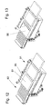
- An identification of the book block 61 can also take place here, eg with barcode / data matrix code / transponder / RF ID or the like. This identification can but also after the measuring / control station 50 or before. If a book block 61 does not pass the qualitative examinations, it is logically rejected, as is the case for example FIGS. 12 and 13 is apparent, then what then arises a gap in the book block flow. However, this is not so bad, because the transfer devices operating according to a rotary translation are able to maintain the predetermined continuous cycle, which is not the case with a purely fixed supply.
- Adaptive accelerations or decelerations which can intervene within the rotary movement of a transfer device as well as in relation to the transport speeds within the book block feeders 60 or the book channels 70, which accelerations and decelerations in speed follow a certain curve function, can be interfered with Smooth the adoption or redirects of the book block 61 and affect the cadence in the transfer of the book block 61 to the next processing station.
- the curve function in one of the transfer devices described above can be influenced by a linear delivery in one direction, not shown in detail, especially if it is necessary to close a gap in the flow of the products, for example, if an accumulation of discharges should occur in connection with the measuring / control station 50, or if, upon acceptance or delivery of the book blocks, a slowing occurs within the speed of the acting curve function.
- the translation follows a motion profile consisting of different adaptive curve functions and / or dwell times.
- a characteristic of the proposed curve function according to the invention is that it can assume a uniform speed in its course as required.
- the discontinuities can be installed in such a way that the maintenance of the originally conceived cadence is ensured.
- FIGS. 12 and 13 therefore, to show how one out of the process according to Fig. 11 indexed excretion of a book block 61 may proceed from further processing.
- Fig. 12 the components Fig. 10
- a discharge point 95 is provided, which is shown here as a telescope-like conveyor belt.
- this Ausschleusstelle comes into operation, and so a faulty book block 61 is excluded from further transport.
- Fig. 13 shown interruption with respect to the original cadence arises due to the resulting interruption time, which is symbolically represented as a route 96 in this figure.
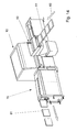
- Fig. 14 shows a single-acting book block feeder 60 of the book block 61 to a transfer device 10.
- book block 61 For the processing station not shown here in the normal case book block 61 are present, which are supplied to the further processing steps.
- coming from the book channel 70 book block 61 a have already been placed in a vertical position, which coincides with the subsequent processing operation.
- the installation of a measuring / control station 50 can be seen in this figure.
- the book block production machines may be formed of a digital printing press and a sheet stacker. These elements can also be preceded by a logistics system or a buffer system.
Landscapes
- Feeding Of Articles By Means Other Than Belts Or Rollers (AREA)
- Folding Of Thin Sheet-Like Materials, Special Discharging Devices, And Others (AREA)
- Discharge By Other Means (AREA)
Applications Claiming Priority (1)
| Application Number | Priority Date | Filing Date | Title |
|---|---|---|---|
| US12/553,321 US8210512B2 (en) | 2009-09-03 | 2009-09-03 | Arrangement for the timed processing of a printed product with the aid of a transfer device |
Publications (2)
| Publication Number | Publication Date |
|---|---|
| EP2292444A2 true EP2292444A2 (fr) | 2011-03-09 |
| EP2292444A3 EP2292444A3 (fr) | 2013-03-13 |
Family
ID=43413894
Family Applications (1)
| Application Number | Title | Priority Date | Filing Date |
|---|---|---|---|
| EP10173311A Withdrawn EP2292444A3 (fr) | 2009-09-03 | 2010-08-18 | Dispositif de traitement cyclé d'imprimés à l'aide d'un dispositif de transfert |
Country Status (3)
| Country | Link |
|---|---|
| US (1) | US8210512B2 (fr) |
| EP (1) | EP2292444A3 (fr) |
| JP (1) | JP5898836B2 (fr) |
Cited By (7)
| Publication number | Priority date | Publication date | Assignee | Title |
|---|---|---|---|---|
| CN103253026A (zh) * | 2012-02-21 | 2013-08-21 | 柯尔布斯有限责任两合公司 | 用来将书芯输送到后续加工设备的引入通道中的设备 |
| EP2631084A3 (fr) * | 2012-02-21 | 2014-03-26 | Kolbus GmbH & Co. KG | Dispositif destiné à alimenter des blocs de livres dans le canal d'entrée d'un dispositif de traitement ultérieur |
| EP2803496A1 (fr) * | 2013-05-17 | 2014-11-19 | Müller Martini Holding AG | Margeur pour une reliure par collage |
| EP2810904A1 (fr) | 2013-06-05 | 2014-12-10 | Müller Martini Holding AG | Transport de pile de feuilles en vrac dans un canal de transport |
| WO2020109345A1 (fr) | 2018-11-30 | 2020-06-04 | Muehlbauer GmbH & Co. KG | Dispositif et procédé de pliage et de mise en réserve des documents de type livre |
| US20230136370A1 (en) * | 2020-02-11 | 2023-05-04 | Heidelberger Druckmaschinen Ag | Method of moving a stack of products by use of a robot |
| DE102024107043A1 (de) * | 2024-03-12 | 2025-09-18 | Manroland Goss Web Systems Gmbh | Vorrichtung und Verfahren zur simultanen Bearbeitung von Buchblöcken |
Families Citing this family (5)
| Publication number | Priority date | Publication date | Assignee | Title |
|---|---|---|---|---|
| EP2727709A1 (fr) * | 2012-10-31 | 2014-05-07 | Nederlandse Organisatie voor toegepast -natuurwetenschappelijk onderzoek TNO | Procédé et appareil pour fabriquer des produits tangibles par fabrication par couches |
| US10987868B2 (en) * | 2012-10-31 | 2021-04-27 | Nederlandse Organisatie Voor Toegepast-Natuurwetenschappelijk Onderzoek Tno | Production line for making tangible products by layerwise manufacturing |
| US11052696B2 (en) * | 2018-12-12 | 2021-07-06 | Canon Finetech Nisca Inc. | Sheet bundle discharging apparatus |
| CN112497950B (zh) * | 2020-10-22 | 2021-06-11 | 中华商务联合印刷(广东)有限公司 | 一种胶装机与折前口机之间的书籍输送装置 |
| CN118176114A (zh) * | 2021-10-25 | 2024-06-11 | 洪克勒股份公司 | 用于分拣书芯的分拣装置 |
Citations (1)
| Publication number | Priority date | Publication date | Assignee | Title |
|---|---|---|---|---|
| EP1645434A1 (fr) | 2004-10-07 | 2006-04-12 | Müller Martini Holding AG | Machine pour traiter de manière synchronisée un bloc de livre constitué au moins d'un feuille imprimé |
Family Cites Families (10)
| Publication number | Priority date | Publication date | Assignee | Title |
|---|---|---|---|---|
| DE1786262B1 (de) * | 1968-09-07 | 1971-11-18 | Walter Sigloch Grossbuchbinder | Verfahren und vorrichtung zum anlegen eines buchblocks an eine beschneidemaschine |
| GB1596173A (en) * | 1976-11-26 | 1981-08-19 | Womako Masch Konstr | Method and apparatus for preparing a pad of sheets for binding |
| DE3123406C2 (de) * | 1981-06-12 | 1985-12-12 | Albert-Frankenthal Ag, 6710 Frankenthal | Vorrichtung zur Produktausrichtung |
| US4500241A (en) * | 1982-01-28 | 1985-02-19 | E.C.H. Will (Gmbh & Co.) | Machine for making ruled pads or the like |
| DE3413222C2 (de) * | 1984-04-07 | 1995-02-09 | Kolbus Gmbh & Co Kg | Verfahren zum Überführen von Buchblocks in das Transportmittel einer Buchbindemaschine und Vorrichtung zur Durchführung des Verfahrens |
| JPH0698854B2 (ja) * | 1988-08-24 | 1994-12-07 | 忠男 宇野 | 起立冊本供給方法と装置 |
| JPH0299827U (fr) * | 1989-01-30 | 1990-08-08 | ||
| US5522588A (en) * | 1995-03-07 | 1996-06-04 | Moore Business Forms, Inc. | Linerless label stacking |
| DE10210843A1 (de) * | 2002-03-12 | 2003-10-09 | Horst Rathert | Klebebinder für die Herstellung von Blocks und Broschüren insbesondere für Kleinauflagen |
| ATE399649T1 (de) * | 2004-03-11 | 2008-07-15 | Mueller Martini Holding Ag | Förderstrecke für buchblocks in einer einrichtung zur herstellung gebundener druckerzeugnisse |
-
2009
- 2009-09-03 US US12/553,321 patent/US8210512B2/en not_active Expired - Fee Related
-
2010
- 2010-08-18 EP EP10173311A patent/EP2292444A3/fr not_active Withdrawn
- 2010-08-27 JP JP2010190320A patent/JP5898836B2/ja not_active Expired - Fee Related
Patent Citations (1)
| Publication number | Priority date | Publication date | Assignee | Title |
|---|---|---|---|---|
| EP1645434A1 (fr) | 2004-10-07 | 2006-04-12 | Müller Martini Holding AG | Machine pour traiter de manière synchronisée un bloc de livre constitué au moins d'un feuille imprimé |
Cited By (18)
| Publication number | Priority date | Publication date | Assignee | Title |
|---|---|---|---|---|
| CN103253026A (zh) * | 2012-02-21 | 2013-08-21 | 柯尔布斯有限责任两合公司 | 用来将书芯输送到后续加工设备的引入通道中的设备 |
| DE102012003604A1 (de) * | 2012-02-21 | 2013-08-22 | Kolbus Gmbh & Co. Kg | Vorrichtung zum Zuführen von Buchblocks in den Einfuhrkanal einer Weiterverarbeitungseinrichtung |
| EP2631084A3 (fr) * | 2012-02-21 | 2014-03-26 | Kolbus GmbH & Co. KG | Dispositif destiné à alimenter des blocs de livres dans le canal d'entrée d'un dispositif de traitement ultérieur |
| DE102012003604B4 (de) * | 2012-02-21 | 2025-04-30 | Müller Martini Holding AG | Vorrichtung zum Zuführen von Buchblocks in den Einfuhrkanal einer Weiterverarbeitungseinrichtung |
| US8915349B2 (en) | 2012-02-21 | 2014-12-23 | Kolbus Gmbh & Co. Kg | Device for feeding book blocks into the infeed channel of a subsequent processing arrangement |
| EP2803496A1 (fr) * | 2013-05-17 | 2014-11-19 | Müller Martini Holding AG | Margeur pour une reliure par collage |
| CN104163054A (zh) * | 2013-05-17 | 2014-11-26 | 海德堡印刷机械股份公司 | 用于胶订机的进料器 |
| US9085423B2 (en) | 2013-06-05 | 2015-07-21 | Mueller Martini Holding Ag | Method and device for feeding loose stacks of sheets into a transport duct |
| CN104228393A (zh) * | 2013-06-05 | 2014-12-24 | 米勒·马蒂尼控股公司 | 松散的纸张堆垛到传输通道中的输送 |
| EP2810904A1 (fr) | 2013-06-05 | 2014-12-10 | Müller Martini Holding AG | Transport de pile de feuilles en vrac dans un canal de transport |
| WO2020109345A1 (fr) | 2018-11-30 | 2020-06-04 | Muehlbauer GmbH & Co. KG | Dispositif et procédé de pliage et de mise en réserve des documents de type livre |
| DE102018009417A1 (de) * | 2018-11-30 | 2020-06-04 | Mühlbauer Gmbh & Co. Kg | Vorrichtung und Verfahren zur Faltung und Bevorratung von Buchdokumenten |
| DE102018009417B4 (de) | 2018-11-30 | 2024-01-18 | Mühlbauer Gmbh & Co. Kg | Vorrichtung und Verfahren zur Faltung und Bevorratung von Buchdokumenten |
| US11878890B2 (en) | 2018-11-30 | 2024-01-23 | Muehlbauer GmbH & Co. KG | Apparatus and method for folding and stocking book documents |
| US20230136370A1 (en) * | 2020-02-11 | 2023-05-04 | Heidelberger Druckmaschinen Ag | Method of moving a stack of products by use of a robot |
| US11952232B2 (en) * | 2020-02-11 | 2024-04-09 | Heidelberger Druckmaschinen Ag | Method of moving a stack of products by use of a robot |
| US12344495B2 (en) | 2020-02-11 | 2025-07-01 | Heidelberger Druckmaschinen Ag | Method of moving a stack of products by use of a robot |
| DE102024107043A1 (de) * | 2024-03-12 | 2025-09-18 | Manroland Goss Web Systems Gmbh | Vorrichtung und Verfahren zur simultanen Bearbeitung von Buchblöcken |
Also Published As
| Publication number | Publication date |
|---|---|
| US8210512B2 (en) | 2012-07-03 |
| JP5898836B2 (ja) | 2016-04-06 |
| EP2292444A3 (fr) | 2013-03-13 |
| US20110054672A1 (en) | 2011-03-03 |
| JP2011051343A (ja) | 2011-03-17 |
Similar Documents
| Publication | Publication Date | Title |
|---|---|---|
| EP2292444A2 (fr) | Dispositif de traitement cyclé d'imprimés à l'aide d'un dispositif de transfert | |
| EP2740695B1 (fr) | Dispositif d'isolation de produits d'impression à partir de piles | |
| EP3182568B1 (fr) | Dispositif de bobinages ondules | |
| DE19955819A1 (de) | Vorrichtung zum Verlangsamen und Führen eines Bogens, und Verfahren hierfür | |
| EP3492229A1 (fr) | Dispositif et procédé de coupe ou de perforation d'une bande de papier | |
| EP2810904B1 (fr) | Transport de pile de feuilles en vrac dans un canal de transport | |
| DE102008049255B4 (de) | Vorrichtung und Verfahren zum Aufstecken von Ventilsäcken | |
| EP2147881A2 (fr) | Dispositif pour déposer des produits plats | |
| EP2602220B1 (fr) | Dispositif et procédé d'assemblage de produits plats, en particulier de produits d'imprimerie | |
| EP2297014B1 (fr) | Dispositif d'insertion et procédé d'insertion | |
| EP2478782B1 (fr) | Dispositif de transport pour produits en forme de tige de l'industrie de traitement du tabac | |
| EP0225994B1 (fr) | Procédé et dispositif pour placer et freiner des feuilles ou des feuilles en paquet imprimées dans une presse à imprimer | |
| EP2133295B1 (fr) | Dispositif et procédé destinés à extraire des produits d'impression plats d'une pile et à les transmettre à un dispositif de transport déroulant | |
| EP0718223B1 (fr) | Dispositif de transfert pour marchandises, notamment pour boítes | |
| DE102007046777A1 (de) | Vorrichtung zum Aufstecken von Säcken auf einen Füllstutzen einer Packmaschine | |
| EP0514783B1 (fr) | Dispositif pour transporter des piles de feuilles en papier | |
| EP2055660B1 (fr) | Dispositif de retournement cadencé d'objets plats | |
| DE1436064C3 (de) | Vorrichtung zum Zusammentragen gefalzter Bogen zu einem Buchblock | |
| EP2265528B1 (fr) | Procédé et dispositif de transport de produits plats | |
| EP1730063B1 (fr) | Systeme a trajectoires de traitement alternatives pour realiser des post-traitements sur des produits, appareil de pliage longitudinal, et procede permettant le fonctionnement synchrone d'un appareil de pliage | |
| CH701621A1 (de) | Vorrichtung und Verfahren zum Ablegen von Produkten. | |
| EP1593633B1 (fr) | Dispositif pour empiler des articles imprimés | |
| EP1934124A1 (fr) | Appareil de pliage longitudinal, procede pour faire fonctionner un appareil de pliage longitudinal, et procede pour synchroniser un appareil de pliage longitudinal | |
| EP2746204B1 (fr) | Dispositif et procédé destinés à faire tourner des objets plats | |
| EP1720786B1 (fr) | Appareil de pliage longitudinal pourvu d'une longueur de freinage |
Legal Events
| Date | Code | Title | Description |
|---|---|---|---|
| PUAI | Public reference made under article 153(3) epc to a published international application that has entered the european phase |
Free format text: ORIGINAL CODE: 0009012 |
|
| AK | Designated contracting states |
Kind code of ref document: A2 Designated state(s): AL AT BE BG CH CY CZ DE DK EE ES FI FR GB GR HR HU IE IS IT LI LT LU LV MC MK MT NL NO PL PT RO SE SI SK SM TR |
|
| AX | Request for extension of the european patent |
Extension state: BA ME RS |
|
| PUAL | Search report despatched |
Free format text: ORIGINAL CODE: 0009013 |
|
| AK | Designated contracting states |
Kind code of ref document: A3 Designated state(s): AL AT BE BG CH CY CZ DE DK EE ES FI FR GB GR HR HU IE IS IT LI LT LU LV MC MK MT NL NO PL PT RO SE SI SK SM TR |
|
| AX | Request for extension of the european patent |
Extension state: BA ME RS |
|
| RIC1 | Information provided on ipc code assigned before grant |
Ipc: B42C 19/08 20060101AFI20130205BHEP |
|
| RBV | Designated contracting states (corrected) |
Designated state(s): AL AT BE BG CH CY CZ DE DK EE ES FI FR GB GR HR HU IE IS IT LI LT LU LV MC MK MT NL NO PL PT RO SE SI SK SM TR |
|
| 17P | Request for examination filed |
Effective date: 20130816 |
|
| 17Q | First examination report despatched |
Effective date: 20150915 |
|
| GRAP | Despatch of communication of intention to grant a patent |
Free format text: ORIGINAL CODE: EPIDOSNIGR1 |
|
| INTG | Intention to grant announced |
Effective date: 20180503 |
|
| STAA | Information on the status of an ep patent application or granted ep patent |
Free format text: STATUS: THE APPLICATION IS DEEMED TO BE WITHDRAWN |
|
| 18D | Application deemed to be withdrawn |
Effective date: 20180914 |