EP2292817B1 - Tissu tissé ou tricoté à partir d'un fil métallique ayant des motifs concaves et convexes - Google Patents
Tissu tissé ou tricoté à partir d'un fil métallique ayant des motifs concaves et convexes Download PDFInfo
- Publication number
- EP2292817B1 EP2292817B1 EP10174831A EP10174831A EP2292817B1 EP 2292817 B1 EP2292817 B1 EP 2292817B1 EP 10174831 A EP10174831 A EP 10174831A EP 10174831 A EP10174831 A EP 10174831A EP 2292817 B1 EP2292817 B1 EP 2292817B1
- Authority
- EP
- European Patent Office
- Prior art keywords
- yarn
- metal
- fabric
- metal fiber
- metal fibers
- Prior art date
- Legal status (The legal status is an assumption and is not a legal conclusion. Google has not performed a legal analysis and makes no representation as to the accuracy of the status listed.)
- Not-in-force
Links
Images





Classifications
-
- D—TEXTILES; PAPER
- D02—YARNS; MECHANICAL FINISHING OF YARNS OR ROPES; WARPING OR BEAMING
- D02G—CRIMPING OR CURLING FIBRES, FILAMENTS, THREADS, OR YARNS; YARNS OR THREADS
- D02G1/00—Producing crimped or curled fibres, filaments, yarns, or threads, giving them latent characteristics
- D02G1/14—Producing crimped or curled fibres, filaments, yarns, or threads, giving them latent characteristics using grooved rollers or gear-wheel-type members
-
- D—TEXTILES; PAPER
- D03—WEAVING
- D03D—WOVEN FABRICS; METHODS OF WEAVING; LOOMS
- D03D15/00—Woven fabrics characterised by the material, structure or properties of the fibres, filaments, yarns, threads or other warp or weft elements used
- D03D15/20—Woven fabrics characterised by the material, structure or properties of the fibres, filaments, yarns, threads or other warp or weft elements used characterised by the material of the fibres or filaments constituting the yarns or threads
- D03D15/242—Woven fabrics characterised by the material, structure or properties of the fibres, filaments, yarns, threads or other warp or weft elements used characterised by the material of the fibres or filaments constituting the yarns or threads inorganic, e.g. basalt
- D03D15/25—Metal
-
- B—PERFORMING OPERATIONS; TRANSPORTING
- B01—PHYSICAL OR CHEMICAL PROCESSES OR APPARATUS IN GENERAL
- B01D—SEPARATION
- B01D39/00—Filtering material for liquid or gaseous fluids
- B01D39/10—Filter screens essentially made of metal
-
- B—PERFORMING OPERATIONS; TRANSPORTING
- B01—PHYSICAL OR CHEMICAL PROCESSES OR APPARATUS IN GENERAL
- B01D—SEPARATION
- B01D39/00—Filtering material for liquid or gaseous fluids
- B01D39/10—Filter screens essentially made of metal
- B01D39/12—Filter screens essentially made of metal of wire gauze; of knitted wire; of expanded metal
-
- B—PERFORMING OPERATIONS; TRANSPORTING
- B21—MECHANICAL METAL-WORKING WITHOUT ESSENTIALLY REMOVING MATERIAL; PUNCHING METAL
- B21F—WORKING OR PROCESSING OF METAL WIRE
- B21F1/00—Bending wire other than coiling; Straightening wire
- B21F1/04—Undulating
-
- B—PERFORMING OPERATIONS; TRANSPORTING
- B21—MECHANICAL METAL-WORKING WITHOUT ESSENTIALLY REMOVING MATERIAL; PUNCHING METAL
- B21F—WORKING OR PROCESSING OF METAL WIRE
- B21F27/00—Making wire network, i.e. wire nets
- B21F27/12—Making special types or portions of network by methods or means specially adapted therefor
- B21F27/18—Making special types or portions of network by methods or means specially adapted therefor of meshed work for filters or sieves
-
- B—PERFORMING OPERATIONS; TRANSPORTING
- B21—MECHANICAL METAL-WORKING WITHOUT ESSENTIALLY REMOVING MATERIAL; PUNCHING METAL
- B21F—WORKING OR PROCESSING OF METAL WIRE
- B21F45/00—Wire-working in the manufacture of other particular articles
-
- D—TEXTILES; PAPER
- D02—YARNS; MECHANICAL FINISHING OF YARNS OR ROPES; WARPING OR BEAMING
- D02G—CRIMPING OR CURLING FIBRES, FILAMENTS, THREADS, OR YARNS; YARNS OR THREADS
- D02G3/00—Yarns or threads, e.g. fancy yarns; Processes or apparatus for the production thereof, not otherwise provided for
- D02G3/02—Yarns or threads characterised by the material or by the materials from which they are made
- D02G3/12—Threads containing metallic filaments or strips
-
- D—TEXTILES; PAPER
- D04—BRAIDING; LACE-MAKING; KNITTING; TRIMMINGS; NON-WOVEN FABRICS
- D04B—KNITTING
- D04B1/00—Weft knitting processes for the production of fabrics or articles not dependent on the use of particular machines; Fabrics or articles defined by such processes
- D04B1/14—Other fabrics or articles characterised primarily by the use of particular thread materials
-
- F—MECHANICAL ENGINEERING; LIGHTING; HEATING; WEAPONS; BLASTING
- F23—COMBUSTION APPARATUS; COMBUSTION PROCESSES
- F23D—BURNERS
- F23D14/00—Burners for combustion of a gas, e.g. of a gas stored under pressure as a liquid
- F23D14/12—Radiant burners
- F23D14/14—Radiant burners using screens or perforated plates
- F23D14/149—Radiant burners using screens or perforated plates with wires, threads or gauzes as radiation intensifying means
-
- F—MECHANICAL ENGINEERING; LIGHTING; HEATING; WEAPONS; BLASTING
- F23—COMBUSTION APPARATUS; COMBUSTION PROCESSES
- F23D—BURNERS
- F23D14/00—Burners for combustion of a gas, e.g. of a gas stored under pressure as a liquid
- F23D14/12—Radiant burners
- F23D14/16—Radiant burners using permeable blocks
-
- F—MECHANICAL ENGINEERING; LIGHTING; HEATING; WEAPONS; BLASTING
- F23—COMBUSTION APPARATUS; COMBUSTION PROCESSES
- F23D—BURNERS
- F23D14/00—Burners for combustion of a gas, e.g. of a gas stored under pressure as a liquid
- F23D14/46—Details
-
- D—TEXTILES; PAPER
- D10—INDEXING SCHEME ASSOCIATED WITH SUBLASSES OF SECTION D, RELATING TO TEXTILES
- D10B—INDEXING SCHEME ASSOCIATED WITH SUBLASSES OF SECTION D, RELATING TO TEXTILES
- D10B2101/00—Inorganic fibres
- D10B2101/20—Metallic fibres
-
- D—TEXTILES; PAPER
- D10—INDEXING SCHEME ASSOCIATED WITH SUBLASSES OF SECTION D, RELATING TO TEXTILES
- D10B—INDEXING SCHEME ASSOCIATED WITH SUBLASSES OF SECTION D, RELATING TO TEXTILES
- D10B2505/00—Industrial
-
- D—TEXTILES; PAPER
- D10—INDEXING SCHEME ASSOCIATED WITH SUBLASSES OF SECTION D, RELATING TO TEXTILES
- D10B—INDEXING SCHEME ASSOCIATED WITH SUBLASSES OF SECTION D, RELATING TO TEXTILES
- D10B2505/00—Industrial
- D10B2505/04—Filters
-
- F—MECHANICAL ENGINEERING; LIGHTING; HEATING; WEAPONS; BLASTING
- F23—COMBUSTION APPARATUS; COMBUSTION PROCESSES
- F23D—BURNERS
- F23D2203/00—Gaseous fuel burners
- F23D2203/10—Flame diffusing means
- F23D2203/103—Flame diffusing means using screens
-
- F—MECHANICAL ENGINEERING; LIGHTING; HEATING; WEAPONS; BLASTING
- F23—COMBUSTION APPARATUS; COMBUSTION PROCESSES
- F23D—BURNERS
- F23D2212/00—Burner material specifications
- F23D2212/20—Burner material specifications metallic
- F23D2212/201—Fibres
Definitions
- the present invention relates to a woven or knitted fabric prepared from a metal fiber having concave-convex patterns, in which frictional force between metal fibers, entanglement and processability are improved.
- a metal fiber fabric As a filter material and a burner material, a metal fiber fabric has been used in view of durability and heat resistance. Meanwhile, a metal fiber fabric has been prepared using a metal fiber bundle or yarn made of heat-resistant metal fibers or ceramic fibers.
- PCT Patent Application No. WO 01/079759 discloses a yarn including a machined metal fiber bundle surrounded by polymer or natural fibers and consolidated with a binding agent, a fabric including the yarn, and a method for manufacturing a gas burner membrane.
- the method for manufacturing the gas burner membrane includes preparing a fabric and removing a binding agent, polymer or natural fibers from the fabric.
- the method for manufacturing the yarn surrounded by the binding agent and the polymer or natural fibers is widely used when preparing a yarn from a machined metal fiber.
- PCT Patent Application No. WO 97/04152 also discloses a textile fabric and a gas burner membrane made of the textile fabric.
- Machined metal filaments having a diameter of 15-150 ⁇ m are consolidated by a binding agent to form a nearly parallel filament bundle, and the consolidated bundle is woven, knitted or braided to prepare the textile fabric.
- U.S. Patent Nos. 4,930,199 and 5,071,713 disclose a yarn which is prepared by surrounding a machined metal fiber with polymer or natural fibers. However, such a yarn cannot be drawn more than the elongation of the polymer. In this regard, there is a limitation on thinning the thickness of the yarn, and it is difficult to manufacture a porous material having finer pores.
- Korean Patent No. 613869 discloses a metal fiber yarn prepared by combing metal fibers which are formed by a melt extraction process and in which orientations are randomly distributed, a fabric prepared from the metal fiber yarn, and a use of the metal fiber yarn as a membrane for a surface combustion burner.
- the metal fiber yarn is prepared by the entanglement of the metal fibers by means of surface protrusions which are naturally formed on the surfaces of the metal fibers during the process of preparing the metal fibers by the melt extraction process.
- the metal fibers are prepared by the melt extraction process, there is a limitation on the frictional force of the metal fibers due to the surface protrusions formed on the surfaces of the metal fibers.
- the metal fiber yarn prepared from a large number of metal fibers such as the above has a problem in that it is difficult to prepare a fabric having lower-density, uniform and fine pores.
- An aspect of the present invention provides woven or knitted fabric prepared from a metal fiber, in which frictional force between metal fibers, entanglement and processability are improved, and a metal fiber yarn including the same.
- An aspect of the present invention also provides a woven or knitted fabric prepared from a metal fiber fabric prepared from the metal fabric yarn and having more uniform and finer pores.
- An aspect of the present invention also provides a filter material and a burner material which are made of the metal fiber fabric.
- a woven or knitted fabric prepared from a metal fiber yarn including a metal fiber having concave-convex patterns formed at intervals of 0.3-50mm in a longitudinal direction of the metal fiber and drawn and the metal fiber yarn has a length of 0.45 m to 10.0m per gram.
- FIG. 1 illustrates a method for manufacturing a metal fiber in which concave-convex patterns are formed using a spur gear
- FIG. 2A is a top sectional view of the metal fiber having the concave-convex patterns formed by passing through the spur gear;
- FIG. 2B is a side view of the metal fiber having the concave-convex patterns formed by passing through the spur gear;
- FIG. 2C is a perspective view of the metal fiber having the concave-convex patterns formed by passing through the spur gear;
- FIG. 3 illustrates a method for manufacturing a metal fiber in which concave-convex patterns are formed using a helical gear
- FIG. 4A is a top sectional view of the metal fiber having the concave-convex patterns formed by passing through the helical gear;
- FIG. 4B is a side view of the metal fiber having the concave-convex patterns formed by passing through the helical gear;
- FIG. 4C is a perspective view of the metal fiber having the concave-convex patterns formed by passing through the helical gear;
- FIG. 5 is a SEM image (magnification (X) : 500) showing the surface of a metal fiber manufactured by a cutting process or a drawing process;
- FIG. 6 is a SEM image (magnification (X) : 500) showing the side surface of a metal fiber manufactured by a melt extraction process;
- FIG. 7A is an image showing a fabric prepared from yarns having 100 strands of fibers with a diameter of 30 ⁇ m (number of yarns: 20/2.54cm);
- FIG. 7B is an image showing a fabric prepared from yarns (FIG. 3B) having 200 strands of fibers with a diameter of 20 ⁇ m (number of yarns: 20/2.54cm);
- FIG. 8 illustrates a metal fiber yarn
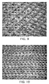
- FIG. 9 is an image showing a fabric prepared by weaving the metal fiber yarn according to the embodiment of the present invention.
- FIG. 10 is an image showing a fabric prepared by knitting the metal fiber yarn according to the embodiment of the present invention.
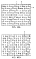
- FIG. 11A illustrates the bottom surface of a fabric having flame holes according to an embodiment of the present invention
- FIG. 11B illustrates the top surface of the fabric having flame holes according to the embodiment of the present invention
- FIG. 12A illustrates a fabric including metal wires as a part of warp
- FIG. 12B illustrates a fabric including metal wires as a part of weft
- FIG. 13 schematically illustrates a drawing process of a metal fiber
- FIG. 14 is an image showing a surface combustion burner using membranes prepared from yarns of example 12 and comparative example 12;
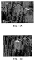
- FIG. 15A is an image showing the lowest load state of the membrane prepared from the yarn of example 12;
- FIG. 15B is an image showing the highest load state of the membrane prepared from the yarn of example 12;
- FIG. 16A is an image showing the lowest load state of the membrane prepared from the yarn of comparative example 12.
- FIG. 16B is an image showing the highest load state of the membrane prepared from the yarn of comparative example 12.
- An aspect of the present invention provides a woven or knitted fabric prepared from a metal fiber in which concave-convex patterns are formed in a longitudinal direction of the metal fiber at regular intervals, specifically, at intervals of from 0.3mm to 50mm.
- the concave-convex patterns are formed at the regular intervals along the longitudinal direction of the metal fiber. That is, the concave-convex patterns may be repeated at intervals of from 0.3mm to 50mm along the longitudinal direction of the metal fiber.
- the concave-convex patterns of the metal fiber may be formed at intervals of 0.3 mm -50mm, specifically 0.3 mm -30mm, more specifically 0.5 mm -18mm.
- the concave-convex patterns are formed at intervals of less than 0.3mm, a large number of concave-convex patterns are formed to increase the frictional force between the metal fibers and therefore a stable drawing is impossible. If the concave-convex patterns are formed at intervals of more than 50mm, the frictional force between the metal fibers and the entanglement are insufficient and therefore the metal fibers may be released from the metal fiber yarn.
- the concave-convex patterns may be formed by passing a metal fiber bundle through a gear.
- the concave-convex patterns may be formed in any kind of metal fibers.
- the number of metal fibers included in the metal fiber bundle which is to be passed through the gear to form the concave-convex patterns thereon in the longitudinal direction of the metal fibers there is no special limitation on the number of metal fibers included in the metal fiber bundle which is to be passed through the gear to form the concave-convex patterns thereon in the longitudinal direction of the metal fibers.
- FIGS. 1 through 4 illustrate a method for forming concave-convex patterns on metal fibers by passing a metal fiber bundle through a gear, and the metal fiber bundle on which the concave-convex patterns are formed.
- the concave-convex patterns may be formed on the metal fibers by passing the metal fiber bundle through a spur gear as illustrated in FIG. 1 , or by passing the metal fiber bundle through a helical gear as illustrated in FIG. 3 .
- the concave-convex patterns illustrated in FIGS. 2B and 2C are formed on the metal fiber bundle. That is, as illustrated in FIG. 2B which shows the side sectional view of the metal fiber, the concave-convex patterns are formed vertically with respect to the longitudinal direction of the metal fiber.
- the metal fiber bundle 32 is passed through the helical gear 31 as illustrated in FIG.
- the concave-convex patterns illustrated in FIGS. 4B and 4C are formed on the metal fiber bundle. That is, as illustrated in FIG. 4B which shows the side sectional view of the metal fiber, the concave-convex patterns are formed inclined with respect to vertical line to the longitudinal direction of the metal fiber.
- the concave-convex patterns may be different depending on the tooth shape of the gear through which the metal fiber is passed.
- the shapes of the concave-convex patterns are not specially limited.
- the concave-convex patterns may have a V-shape, a U-shape, or a U-shape.
- the concave-convex patterns may be formed on a metal fiber which is generally known to those skilled in the art, and/or a metal fiber prepared by a method which is generally known to those skilled in the art.
- examples of the metal fiber include a metal fiber made of a Fecralloy which is a Fe-Cr-Al alloy.
- Fecralloy is a generally-known alloy.
- Fecralloy may include 18-27wt% of chromium (Cr), 3-7wt% of aluminum (Al), specifically 5-7wt%, and the remaining wt% of iron (Fe).
- an improved Fecralloy which further includes 0.05-0.5wt% of zirconium (Zr) and/or yttrium (Y), specifically 0.1-0.3wt%, may be used.
- the metal fiber include a stainless steel metal fiber, specifically, a stainless steel 316L metal fiber.
- the concave-convex patterns may be formed on a metal fiber prepared by a cutting process, a drawing process, or a melt extraction process.
- the surfaces of the metal fibers prepared by the machining process such as the cutting process or the drawing process are smooth and without protrusions. Since there is no frictional force between the metal fibers having the smooth surfaces, it is difficult to prepare a yarn from such metal fibers.
- a plurality of protrusions having a height of several micrometers, specifically 1-5 ⁇ m, are formed on the surfaces of the metal fibers prepared by the melt extraction process.
- the metal fibers may be released from the metal fiber yarn.
- the frictional force between the metal fibers is insufficient.
- a single strand of the yarn must be prepared from a relatively large number of metal fibers such as 50-100 strands of metal fibers. Even in this case, the metal fibers are released from the metal fiber yarn, and the form of the metal fiber yarn is not maintained.
- the concave-convex patterns are formed on the metal fibers, sufficient friction force and entanglement are provided between the metal fibers prepared by the machining process such as the cutting process or the drawing process and the metal fibers prepared by the melt extraction process. Hence, such metal fibers may be easily processed into the metal fiber yarn, and the metal fibers will not be released from the metal fiber yarn.
- the number of metal fibers used for forming a single strand of the yarn is not limited. Specifically, the yarn, including any number of metal fibers such as an example, about 10-250 strands or more of metal fiber, may be easily prepared. Furthermore, the metal fiber yarn may be prepared without using an additional binder and/or polymer.
- the metal fiber yarn prepared from the metal fibers according to the embodiment ensures excellent and high porosity because of the concave-convex patterns formed on the metal fibers, and a plurality of very fine and uniform pores are formed in the metal fiber yarn and fabric.
- the diameter and length of the metal fibers usable when preparing the metal fiber yarn are limited due to weak frictional force, entanglement and processability (specifically, processability of the metal fibers to the metal fiber yarn).
- the conventional metal fiber yarn has been prepared using the metal fibers having a diameter of 10 ⁇ m -100 ⁇ m, specifically 30 ⁇ m -100 ⁇ m, and a length of 10 cm -100cm.
- the metal fibers according to the embodiment have the concave-convex patterns, the frictional force between the metal fibers, the entanglement and the processability are increased.
- the diameter and length of the metal fibers usable when preparing the metal fiber yarn there is no specific limitation on the diameter and length of the metal fibers usable when preparing the metal fiber yarn. That is, the metal fiber yarn may be easily prepared using metal fibers having a diameter of less than 10 ⁇ m and metal fibers having a diameter of more than 100 ⁇ m, as well as metal fibers having a diameter of 10 ⁇ m -100 ⁇ m. Also, the metal fiber yarn may be easily prepared using metal fibers having a length of less than 10cm and metal fibers having a length of more than 100cm, as well as the metal fibers having a length of 10 cm
- yarn including a large number of thin metal fibers is preferred to yarn including a small number of thick metal fibers under the condition of the same equivalent diameter.
- yarn having 200 strands of fibers having a diameter of 20 ⁇ m is preferred to yarn having 100 strands of fibers having a diameter of 30 ⁇ m (yarn diameter: about 0.1mm, FIG. 7A ).
- the metal fibers according to the embodiment have excellent elasticity because of the concave-convex patterns formed on the metal fibers. Due to the elasticity thereof, the metal fibers may be easily processed into the metal fiber yarn and the metal fabric using the same, and the metal fibers may be freely modified in various shapes. Also, the metal fiber yarn and the metal fabric using the same have a soft texture.
- the metal fibers having the concave-convex patterns according to the embodiment may be drawn and twisted to prepare the metal fiber yarn. Meanwhile, since the conventional metal fiber yarn has insufficient frictional force and entanglement between the metal fibers, it is not processed into a false twist yarn, but into a twisting yarn. However, the metal fibers having the concave-convex patterns according to the embodiment can be processed into a false twist yarn as well as a twisting yarn because of the increased frictional force and entanglement between the metal fibers. In the case of the twisting yarn and the false twist yarn prepared from the metal fibers according to the embodiment, metal fibers are not released, thereby stably maintaining the form of the yarn.
- the metal fibers since the frictional force between the metal fibers is improved, the metal fibers have excellent entanglement.
- the torsion rate is not specifically limited.
- the false twist yarn is prepared by drawing and twisting the metal fibers to manufacture the metal fiber yarn and untwisting the metal fiber yarn.
- the torsion rate of the metal fiber is not specially limited.
- the metal fibers may be twisted to have a porosity and pore distribution suitable for the purpose of the metal fiber fabric prepared from the metal fiber yarn.
- the metal fiber yarn including the metal fibers according to the embodiment may be processed into a false twist yarn or a twisting yarn, considering the ejection of a gas fuel at pores between the metal fibers, differential pressure, and combustion efficiency.
- the yarn may be prepared by twisting the metal fibers, e.g., at 3-5 turns/m.
- the metal fiber yarn including the metal fibers according to the embodiment may be processed into a false twist yarn or a twisting yarn, considering the filtration performance of dust particle/foreign object of the metal fiber fabric and the increase in differential pressure due to the accumulation of dust particles or foreign objects at pores.
- the yarn may be prepared by twisting the metal fibers, e.g., at 1-15 turns/m, preferably 10-15 turns/m.
- the metal fibers may be processed into a twisting yarn by applying the torsion rate within the above-described range or a false twist yarn according to the intended use of the metal fabric, specifically, the intended use of the metal fabric as a burner material and/or a filter material.
- the metal fiber yarn according to the embodiment may have a length of 0.45-10.0 m per gram (0.45-10.0 Nm).
- the length of the yarn per gram is less than 0.45 m, the yarn becomes thick and thus it is not suitable in view of porosity.
- the length of the yarn per gram is more than 10.0 m, the yarn is not prepared.
- FIG. 8 illustrates a metal fiber yarn 81 including a plurality of metal fibers 82 according to an embodiment.
- the metal fiber yarn according to the embodiment may be prepared by continuing to finely draw and twist the metal fibers in which the concave-convex patterns are formed. Meanwhile, the false twist yarn is prepared by drawing and twisting the metal fibers and untwisting the twisted metal fibers.
- the metal fibers 82 are well entangled together due to the concave-convex patterns. Also, since the frictional force between the metal fibers is increased due to the concave-convex patterns, metal fibers are not released from the yarn, thereby stably maintaining the form of the yarn. Furthermore, due to the concave-convex patterns of the metal fibers constituting the yarn, a plurality of fine and uniform pores are formed between the metal fibers, thereby providing the excellent and high porosity. Moreover, the metal fibers having the concave-convex patterns according to the embodiment may be easily processed in a subsequent process and have soft texture.
- the metal fiber yarn according to the embodiment may be woven into a fabric by a general method which is known to those skilled in the art.
- a photo of a fabric prepared by a weaving process and a fabric prepared by a knitting process are illustrated in FIGS. 9 and 10 , respectively.
- the fabric according to the embodiment may be prepared from the metal fiber yarn by substantially weaving warp yarn B and weft yarn B' at right angles with relation to one another as illustrated in FIGS. 11A and 11B .
- the metal fiber fabric may include the metal fiber yarn having 5-30 strands per 2.54 cm.
- the number of the metal fiber yarn in the metal fabric is less than 5 strands/2.54 cm, the pore of the fabric is too large, especially when the yarn diameter is small.
- the number of the metal fiber yarn is more than 30 strands/2.54cm, the pore is clogged, especially when the yarn diameter is large.
- the weft yarns and the warp yarns are disposed to be substantially vertical to one another, and flame holes A and A' having sides defined by two parallel warps and two parallel wefts are formed on both sides of the fabric.
- the flame holes refer to parts which are slightly recessed from the bottom and top of the fabric.
- the aspect ratio of the flame hole i.e. the ratio of width : length
- the aspect ratio of the flame hole is 10:1 or less, specifically, 1:1 to 10:1.
- the aspect ratio of the flame hole exceeds 10
- the flame hole is formed through the lower yarn of 3-4 strands. Consequently, the structure of the fabric becomes loose. Meanwhile, only if the porosity is not problematic, the fabric may be prepared to have the flame holes whose aspect ratio is 10:1 or less.
- the metal fiber yarn is prepared using the metal fibers having the concave-convex patterns, there is no limitation on the thickness and/or the length of the metal fiber used in preparing the metal fiber yarn. Hence, metal fibers thinner than the metal fibers which is conventionally used in preparing the conventional metal fiber yarn may be used. Furthermore, metal fiber yarn having a stable form may be prepared, even though a smaller number of metal fibers are used. As such, since the metal fiber yarn is prepared from a small number of metal fibers and/or thin metal fibers, a metal fiber fabric having a low density may be prepared as compared with the conventional art.
- the density of the fabric may be 4.0kg/m 2 or less, specifically, 0.1-4.0kg/m 2 .
- the lower density of the fabric is favorable in view of the reduction in differential pressure. Therefore, even though the lower limit value for the density of the fabric is not specially limited, if the density of the fabric is less than 0.1kg/m 2 , the interval between the metal fiber yarns constituting the fabric is so wide that the smooth combustion or the dust filtration performance is insufficient.
- the density of the fabric is 0.1kg/m 2 or more. Meanwhile, if the density of the fabric exceeds 4.0kg/m 2 , the interval between the metal fiber yarns is so narrow that the porosity is lowered and the differential pressure is increased. Thus, it is unsuitable in view of the ejection of fuel gas and the filtration performance.
- the fabric prepared to have a density of 0.1-4.0kg/m 2 has a thickness of 0.3-2.5mm.
- the porosity of the fabric is 75-95%.
- the woven or knitted fabric according to the embodiment of the present invention may be used as a filter material and/or a burner material, specifically, as a membrane for a surface combustion burner, a pre-filter for water treatment, and a particulate filter.
- metal meshes are attached to both sides of the metal fiber fabric and then the metal fiber fabric to which the metal meshes are attached is processed, e.g., in a wrinkled shape.
- the metal meshes attached to both sides of the metal fiber fabric are processed in a fabric form, they are easily damaged.
- metal wires are used instead of the metal fiber yarns used as the warp yarns and/or the weft yarns.
- the metal fiber yarns and the metal wires may be woven together to prepare the metal fiber fabric including the metal wires.
- the metal wires may be used as warps and/or wefts. That is, the woven fabric according to the embodiment of the present invention may be prepared from the metal fiber yarns and the metal wires by using the metal wires as at least one warp, at least one weft, or both of at least one warp and at least one weft among the plurality of warps and wefts.
- the number of the metal wires usable in preparing the metal fiber fabric is not specially limited.
- the metal wires may be used at any position of the warps and/or the wefts, at any interval, and/or in any number, considering the physical properties required when used as the burner material or the filter material, for example, combustion performance, filtration performance, and strength.
- the metal wire which is made of the same kinds of metal with the metal fiber yarn can be used.
- the metal wire having a diameter of 0.07 mm to 3mm may be used. If the diameter of the metal wire is less than 0.07mm, the metal wire is thin and thus the tensile strength is weak. In this regard, it is unfavorable because there is no great difference from the metal fiber. If the diameter of the metal wire exceeds 3mm, the metal wire is too thick. Hence, in the case in which the metal fiber fabric including the metal wires is used as the burner material, thermal deformation occurs at high temperature.
- the metal fiber woven or knitted fabric prepared using the metal wires includes the metal wires therein.
- the metal fiber fabric when used as a burner material or a filter material, no additional metal meshes are required as compared with the conventional art.
- the metal wires inside the metal fiber fabric improve its strength, and the dense pores formed inside the metal fiber fabric by the metal wires further improve the combustion efficiency of the burner material and the filtration efficiency of the filter material.
- FIG. 12A illustrates a fabric prepared using metal wires as warps C instead of metal fiber yarns
- FIG. 12B illustrates a fabric prepared using metal wires as wefts C' instead of metal fibers.
- the metal fiber woven or knitted fabric prepared from the yarn including the metal fibers having the concave-convex patterns according to the embodiment includes a plurality of uniform, regular and fine pores, it is suitable for a filter material for filtering fine dust particles and/or foreign objects. Also, since a fuel is finely and regularly ejected through the fine pores, a gas flow rate may be increased between the metal fibers, even in the case that a small amount of fuel is supplied. In this regard, the metal fiber fabric is suitable for the burner material because the fuel is stably burnt.
- the fine pores between the metal fibers on which the concave-convex patterns are formed serve as fine flame holes, a wide combustion characteristic is exhibited throughout the high-load and low-load areas, and a more excellent heating effect is exhibited by the uniform flame distribution and the flame splitting effect. Moreover, improved differential pressure performance (reduced differential pressure) is exhibited.
- Embodiment 1 Preparation and evaluation of yarn using metal fibers prepared by cutting process
- a bundle of metal fibers (length: 40cm) having diameters listed in Table 2 below were prepared in a cutting process. Then, by passing the bundle of metal fibers through the spur gear 11 of FIG. 1 or the helical gear 31 of FIG. 3 , the V-shaped concave-convex patterns illustrated in FIG. 2C or 4C were formed on the metal fibers at intervals listed in Table 2 below.
- the metal fiber included 22wt% of chromium (Cr), 5.5wt% of aluminum (Al), and the remaining wt% of iron (Fe).
- the metal fibers of comparative examples 1 to 5 and the metal fibers of embodiments 1 to 6 were drawn by passing them between rollers having different rotating speeds and having a comb shape on the surfaces thereof in a longitudinal direction of the metal fiber. Then, the drawn metal fibers were twisted to prepare yarns, one strand of which had the metal fiber strands and the number of turns listed in Table 2 below. The length of the prepared yarns was 0.55 m per gram. Meanwhile, the false twist yarn was prepared by twisting the metal fibers to manufacture a yarn and untwisting the yarn.
- Embodiment 2 Preparation and evaluation of yarn using metal fibers prepared by drawing process
- a bundle of metal fibers (length: 100cm) having diameters listed in Table 3 below were prepared in a drawing process. Then, by passing the bundle of metal fibers through the spur gear 11 of FIG. 1 or the helical gear 31 of FIG. 3 , the V-shaped concave-convex patterns illustrated in FIG. 2C or 4C were formed on the metal fibers at intervals listed in Table 3 below.
- the metal fiber included 22wt% of chromium (Cr), 5.5wt% of aluminum (Al), and the remaining wt% of iron (Fe).
- the metal fiber yarns meeting the conditions of Table 3 below were prepared using the metal fibers of comparative examples 6 to 10 and the metal fibers of examples 7 to 12 in the same manner as the embodiment 1. Then, the dimensional stability of the prepared metal fiber yarns was evaluated. The length of the yarns was 1.1 m per gram.
- Embodiment 3 Preparation and evaluation of yarn using metal fibers prepared by melt extraction process
- a bundle of metal fibers (length: 10-18cm) having diameters listed in Table 4 below were prepared in a melt extraction process. Then, by passing the bundle of metal fibers through the spur gear 11 of FIG. 1 or the helical gear 31 of FIG. 3 , the V-shaped concave-convex patterns illustrated in FIG. 2C or 4C were formed on the metal fibers at intervals listed in Table 4 below.
- the metal fiber included 22wt% of chromium (Cr), 5.5wt% of aluminum (Al), and the remaining wt% of iron (Fe).
- the metal fiber yarns meeting the conditions of Table 4 below were prepared using the metal fibers of comparative examples 11 to 15 and the metal fibers of examples 13 to 18 in the same manner as the embodiment 1. Then, the dimensional stability of the prepared metal fiber yarns was evaluated. The length of the yarns was 0.55 m per gram.
- Embodiment 4 Air permeability of fabric
- FIG. 9 and FIG. 11 Three fabric samples illustrated in FIG. 9 and FIG. 11 were woven by using the yarn of example 12 and the yarn of comparative example 12 as the warp yarn and the weft yarn, respectively.
- the density of the fabric was 1.5kg/m 2
- the thickness of the fabric was 1.5mm.
- flame holes having an aspect ratio (i.e. the ratio of width : length) of 5:1 were formed on both sides of the fabric.
- the number of the yarns used as the warp yarn and the weft yarn was 20 per inch in the width and length of the fabric, and the porosity of the fabric was 90%.
- the minimum pore diameter and the average pore diameter of the fabric were measured using a porosimeter and shown in Table 5 below. Also, the air permeability of each fabric was measured using the KS K 0570-1997 Frazier method and its average was shown in Table 6 below.
- the minimum pore diameter and the average pore diameter of the fabric were smaller than those of the comparative fabric. It can be seen that the metal fiber fabric having finer pores were prepared by using the metal fiber yarn having the metal fibers with the concave-convex patterns according to the embodiment. Meanwhile, the fabric had two times the air permeability of the comparative fabric. Hence, it could be confirmed that fine pores were formed in the fabric which was prepared from the metal fiber yarn having the concave-convex pattern according to the embodiment, and the air permeability was improved (that is, a small differential pressure was applied).
- Embodiment 5 Evaluation of combustion efficiency when fabric is used as burner material
- the yarns prepared in example 12 and comparative example 12 were woven to prepare the fabrics of FIGS. 9 and 11 which have the density of 1.5kg/m 2 and the thickness of 1.5mm. As illustrated in FIGS. 11A and 11B , flame holes having an aspect ratio (i.e. ratio of width : length) of 5:1 were formed on both sides of the fabric. The number of the yarns used as the warps and the wefts was 20 per inch in the width and length of the fabric, and the porosity of the fabric was 90%.
- FIG. 14 is a picture of an fabric prepared from the yarn of example 1 (hereinafter, referred to as fabric 1) and a comparative fabric prepared from the yarn of comparative example 12 (hereinafter, referred to as a comparative fabric 1) which were applied as a membrane in a surface combustion burner.
- a mixture gas of air and fuel gas was injected into the respective fabrics and burnt while changing the mixture ratio thereof to a value of ⁇ which is defined as a ratio of air/fuel gas.
- a mixture gas of air and fuel gas was burnt while changing the mixture ratio ⁇ thereof to 1.05, 1.25, and 1.42.
- the lowest heating value of the fabric 1 prepared from the yarn of example 12 was 300 kW/m 2 ( FIG. 15A )
- the lowest heating value of the comparative fabric 1 prepared from the yarn of comparative example 12 was 418 kW/m 2 ( FIG. 16A ).
- the highest heating value of the fabric 1 was 1,500 kW/m 2 ( FIG. 15B ), and the highest heating value of the comparative fabric 1 was 1,063 kW/m 2 ( FIG. 16B ).
- Embodiment 6 Evaluation of fabric used as filter material
- the metal mesh (porosity: 75%, diameter: 0.2mm) included 22wt% of chromium (Cr), 5.5wt% of aluminum (Al), and the remaining wt% of iron (Fe).
- the metal wire also included 22wt% of chromium (Cr), 5.5wt% of aluminum (Al), and the remaining wt% of iron (Fe).
- the fabric 1 prepared from the metal fiber yarn according to the embodiment exhibited more excellent tensile strength than that of the comparative fabric 1. Also, the fabric 2 prepared using the metal wires as the warp yarn exhibited the warp-direction tensile strength comparable to that of the complex body.
- the fabric 1 exhibited more excellent collection efficiency than that of the comparative fabric 1.
- the metal fibers having the concave-convex patterns formed at regular intervals in the longitudinal direction exhibit the improved frictional force between the metal fibers, entanglement, and processability due to the concave-convex patterns on the metal fibers.
- the metal fibers exhibit the excellent processability as the metal fiber yarn. Therefore, due to the concave-convex patterns, the metal fiber according to the embodiment is well entangled with other metal fibers, and the entangled state between the metal fibers is maintained by the large frictional force between the metal fibers. Also, the fibers are not released from the metal fiber yarn. Therefore, in preparing the metal fiber yarn, no additional binder and/or polymer are/is required.
- the metal fiber yarn may be easily prepared using those metal fibers.
- the metal fiber having the concave-convex patterns according to the embodiment has excellent elasticity due to the concave-convex patterns. Due to the elasticity, the metal fiber yarn may be easily prepared and may be easily processed into the metal fabric. The metal fiber yarn may be processed into any type of fabric. The prepared metal fiber yarn and the metal fabric using the same have a soft texture.
- the metal fiber yarn including the metal fibers having the concave-convex patterns according to the embodiment maintains its form stably because metal fibers are not released. Also, the metal fiber yarn has a plurality of uniform and fine pores.
- the metal fiber yarn having excellent dimensional stability and air permeability may be prepared using the metal fibers having any length and/or thickness.
- one strand of the yarn may be formed with any number of metal fibers.
- the fabric prepared from the metal fiber yarn according to the embodiment also has the more improved porosity. Therefore, when the fabric according to the embodiment is used as the filter material, finer dust particles and/or foreign objects may be effectively filtered. Also, when the fabric according to the embodiment is used as the burner material, the heating effect is improved by the excellent porosity of the fabric and the excellent flame splitting effect due to the plurality of fine and uniform pores, and the wide combustion area and the high combustion rate are exhibited. Moreover, the fabric according to the embodiment exhibits improved differential pressure performance.
Landscapes
- Engineering & Computer Science (AREA)
- Mechanical Engineering (AREA)
- Textile Engineering (AREA)
- Chemical & Material Sciences (AREA)
- Combustion & Propulsion (AREA)
- General Engineering & Computer Science (AREA)
- Chemical Kinetics & Catalysis (AREA)
- Inorganic Chemistry (AREA)
- Woven Fabrics (AREA)
- Filtering Materials (AREA)
- Yarns And Mechanical Finishing Of Yarns Or Ropes (AREA)
Claims (8)
- Tissu préparé à partir d'un fil de fibre métallique comprenant un fil métallique présentant des motifs concaves et convexes qui sont formés à des intervalles de 0,3 à 50 mm dans une direction longitudinale de la fibre métallique et qui sont étirés et le fil de fibre métallique ayant une longueur de 0,45 à 10,0 m par gramme et le tissu étant tissé ou tricoté.
- Tissu selon la revendication 1, dans lequel le tissu a une densité de 0,1 à 4,0 kg/m2.
- Tissu selon la revendication 1, dans lequel le tissu comprend 5 à 30 brins du fil de fibre métallique en tant que chaîne et trame pour 2,54 cm (pouce) de tissu.
- Tissu tissé selon la revendication 1 comprenant un fil métallique et le fil de fibre métallique comprenant une fibre métallique présentant des motifs concaves et convexes qui sont formés à des intervalles de 0,3 à 50 mm dans une direction longitudinale de la fibre métallique et qui sont étirés et le fil de fibre métallique ayant une longueur de 0,45 à 10,0 m par gramme, le fil métallique étant utilisé pour au moins un fil de chaîne, au moins un fil de trame, ou à la fois au moins un fil de chaîne et au moins un fil de trame parmi une pluralité de chaînes et de trames.
- Tissu selon la revendication 4, dans lequel le fil métallique a un diamètre de 0,07 mm à 3 mm.
- Tissu selon l'une quelconque des revendications 1 à 5, dans lequel le fil de fibre métallique présente une torsion ou une fausse torsion.
- Matériau de brûleur comprenant le tissu selon l'une quelconque des revendications 1 à 6.
- Matériau de filtre comprenant le tissu selon l'une des revendications 1 à 6.
Applications Claiming Priority (1)
| Application Number | Priority Date | Filing Date | Title |
|---|---|---|---|
| KR1020090083549A KR101136126B1 (ko) | 2009-09-04 | 2009-09-04 | 금속섬유, 이를 포함하는 금속섬유 얀, 금속섬유 직물, 금속섬유 직물의 제조방법 및 용도 |
Publications (2)
| Publication Number | Publication Date |
|---|---|
| EP2292817A1 EP2292817A1 (fr) | 2011-03-09 |
| EP2292817B1 true EP2292817B1 (fr) | 2012-11-14 |
Family
ID=41551947
Family Applications (1)
| Application Number | Title | Priority Date | Filing Date |
|---|---|---|---|
| EP10174831A Not-in-force EP2292817B1 (fr) | 2009-09-04 | 2010-09-01 | Tissu tissé ou tricoté à partir d'un fil métallique ayant des motifs concaves et convexes |
Country Status (2)
| Country | Link |
|---|---|
| EP (1) | EP2292817B1 (fr) |
| KR (1) | KR101136126B1 (fr) |
Cited By (1)
| Publication number | Priority date | Publication date | Assignee | Title |
|---|---|---|---|---|
| RU2553302C1 (ru) * | 2013-11-19 | 2015-06-10 | Федеральное государственное бюджетное образовательное учреждение высшего профессионального образования "Самарский государственный аэрокосмический университет имени академика С.П. Королева" (национальный исследовательский университет)" (СГАУ) | Фильтрующий элемент и способ его изготовления |
Families Citing this family (11)
| Publication number | Priority date | Publication date | Assignee | Title |
|---|---|---|---|---|
| KR101335553B1 (ko) * | 2011-01-25 | 2013-12-03 | 그린화이어주식회사 | 심리스 원통형 금속 섬유 매트의 제조 방법 |
| EP2690360A1 (fr) * | 2012-07-24 | 2014-01-29 | Green Fire Co., Ltd. | Corps cylindrique en fibres métalliques sans soudure et son procédé de fabrication |
| KR101429936B1 (ko) * | 2013-05-13 | 2014-08-18 | 주식회사 지비엠 | 내구성과 꼬임특성이 개선된 금속 필라멘트 번들, 이로부터 제조된 금속직물, 및 이 직물로 제조된 연소매체 |
| DE102017109152B4 (de) | 2017-04-28 | 2019-01-03 | Voith Patent Gmbh | Infrarot-Strahler sowie Verfahren zur Montage eines solchen |
| CN108031188A (zh) * | 2017-12-20 | 2018-05-15 | 四会市华通金属筛网制品有限公司 | 一种滤水网 |
| CN108950797B (zh) * | 2018-06-15 | 2021-01-08 | 阿斯福特纺织(漳州)有限公司 | 一种高档涤纶面料的成型工艺 |
| KR20210066456A (ko) | 2019-11-28 | 2021-06-07 | 화이버텍 (주) | 무가압 소결을 이용한 필터미디어 제조방법 |
| IT202200003048U1 (it) * | 2022-07-20 | 2024-01-20 | Beckett Thermal Solutions S R L | Membrana di combustione per un bruciatore a gas, realizzato mediante fili a fibre continue |
| IT202200015258A1 (it) * | 2022-07-20 | 2024-01-20 | Beckett Thermal Solutions S R L | Membrana di combustione per un bruciatore a gas, realizzato mediante fili a fibre continue |
| CN115262055B (zh) * | 2022-09-09 | 2024-07-09 | 石狮市富华纺织发展有限公司 | 抗菌涤纱及其生产工艺 |
| CN116695306B (zh) * | 2023-06-17 | 2026-04-10 | 温州威龙被服有限公司 | 一种吸水速干校服布料生产工艺 |
Family Cites Families (7)
| Publication number | Priority date | Publication date | Assignee | Title |
|---|---|---|---|---|
| DE7521192U (de) * | 1975-07-03 | 1976-12-30 | N.V. Bekaert S.A., Zwevegem (Belgien) | Gekraeuseltes metallfilamentbuendel |
| BE1000278A3 (nl) * | 1987-01-30 | 1988-10-04 | Bekaert Sa Nv | Werkwijze ter vervaardiging van tandrol-gekroesde metaalvezels en produkten omvattende deze vezels. |
| CA1320616C (fr) | 1987-12-09 | 1993-07-27 | Akira Yanagisawa | Methode et appareil de fabrication de fibres |
| BE1001539A3 (nl) | 1988-03-17 | 1989-11-21 | Bekaert Sa Nv | Metaalvezels verkregen door gebundeld trekken. |
| JPH0949124A (ja) * | 1995-08-09 | 1997-02-18 | Tokyo Seiko Co Ltd | 金属フィラメントの製造装置及び製造方法 |
| US20020029453A1 (en) * | 2000-09-11 | 2002-03-14 | Quick Nathaniel R. | Apparatus and process for producing high quality metallic fiber tow |
| KR100613869B1 (ko) * | 2005-01-17 | 2006-09-19 | 화이버텍 (주) | 금속섬유 얀, 이로부터 제조된 직물, 직물의 제조방법 및이의 용도 |
-
2009
- 2009-09-04 KR KR1020090083549A patent/KR101136126B1/ko not_active Expired - Fee Related
-
2010
- 2010-09-01 EP EP10174831A patent/EP2292817B1/fr not_active Not-in-force
Cited By (1)
| Publication number | Priority date | Publication date | Assignee | Title |
|---|---|---|---|---|
| RU2553302C1 (ru) * | 2013-11-19 | 2015-06-10 | Федеральное государственное бюджетное образовательное учреждение высшего профессионального образования "Самарский государственный аэрокосмический университет имени академика С.П. Королева" (национальный исследовательский университет)" (СГАУ) | Фильтрующий элемент и способ его изготовления |
Also Published As
| Publication number | Publication date |
|---|---|
| EP2292817A1 (fr) | 2011-03-09 |
| KR20090108573A (ko) | 2009-10-15 |
| KR101136126B1 (ko) | 2012-04-17 |
Similar Documents
| Publication | Publication Date | Title |
|---|---|---|
| EP2292817B1 (fr) | Tissu tissé ou tricoté à partir d'un fil métallique ayant des motifs concaves et convexes | |
| EP0092819B1 (fr) | Matière filtrante et procédé de fabrication | |
| AU2010283240B2 (en) | Filtration cloth for dust collection machine | |
| CA2226990C (fr) | Tissu textile constitue de faisceaux de filaments metalliques usines | |
| KR20120128617A (ko) | 해도 복합 섬유, 극세 섬유 및 복합 구금 | |
| JP6511289B2 (ja) | 内燃機関用プレエアフィルタ | |
| EP1681378B1 (fr) | Fil de fibres métalliques et étoffe contenant des fils de fibres métalliques | |
| JP3339283B2 (ja) | エアーフィルター用不織布およびそれを用いてなるエアーフィルター装置 | |
| JP6265775B2 (ja) | 液体保持材 | |
| JP3744232B2 (ja) | フィルター用基材およびフィルター装置 | |
| KR20120024922A (ko) | 금속섬유, 이를 포함하는 금속섬유 얀, 금속섬유 직물, 금속섬유 직물의 제조방법 및 용도 | |
| JP5630254B2 (ja) | 複合繊維 | |
| JPH11170413A (ja) | 不織布複合低密度織物 | |
| JP3969601B2 (ja) | ろ過布およびそれからなるバグフィルター | |
| JP3146891B2 (ja) | ろ過布 | |
| JP3861520B2 (ja) | 筒状フィルター | |
| CN108778458B (zh) | 层合聚芳硫醚耐热过滤器 | |
| JP3799854B2 (ja) | エアーフィルター | |
| JP3622334B2 (ja) | フィルター用不織布 | |
| JP2021004431A (ja) | 海島繊維 | |
| JP2005281904A (ja) | 耐熱性布帛およびプリーツ型バグフィルターならびに耐熱性布帛の製造方法 | |
| JP3861511B2 (ja) | 筒状フィルター | |
| JP3867241B2 (ja) | 殊に濾過のための、金属からなる平面構造体および平面構造体の製造方法ならびに平面構造体の使用 | |
| CN120018893A (zh) | 过滤介质和过滤器 | |
| HK1015426A (en) | Textile fabric comprising bundles of machined metal filaments |
Legal Events
| Date | Code | Title | Description |
|---|---|---|---|
| PUAI | Public reference made under article 153(3) epc to a published international application that has entered the european phase |
Free format text: ORIGINAL CODE: 0009012 |
|
| 17P | Request for examination filed |
Effective date: 20100901 |
|
| AK | Designated contracting states |
Kind code of ref document: A1 Designated state(s): AL AT BE BG CH CY CZ DE DK EE ES FI FR GB GR HR HU IE IS IT LI LT LU LV MC MK MT NL NO PL PT RO SE SI SK SM TR |
|
| AX | Request for extension of the european patent |
Extension state: BA ME RS |
|
| GRAP | Despatch of communication of intention to grant a patent |
Free format text: ORIGINAL CODE: EPIDOSNIGR1 |
|
| RIC1 | Information provided on ipc code assigned before grant |
Ipc: B21F 27/18 20060101ALI20120229BHEP Ipc: B01D 39/12 20060101ALI20120229BHEP Ipc: B21F 45/00 20060101ALI20120229BHEP Ipc: B21F 1/04 20060101ALI20120229BHEP Ipc: D02G 1/14 20060101AFI20120229BHEP Ipc: F23D 14/46 20060101ALI20120229BHEP Ipc: B01D 39/10 20060101ALI20120229BHEP Ipc: D02G 3/12 20060101ALI20120229BHEP Ipc: F23D 14/14 20060101ALI20120229BHEP Ipc: F23D 14/16 20060101ALI20120229BHEP |
|
| RTI1 | Title (correction) |
Free format text: WOVEN OR KNITTED FABRIC PREPARED FROM A CONCAVE-CONVEX PATTERNED METAL FIBER YARN |
|
| RIN1 | Information on inventor provided before grant (corrected) |
Inventor name: SUK, CHANG HWAN |
|
| GRAS | Grant fee paid |
Free format text: ORIGINAL CODE: EPIDOSNIGR3 |
|
| GRAA | (expected) grant |
Free format text: ORIGINAL CODE: 0009210 |
|
| AK | Designated contracting states |
Kind code of ref document: B1 Designated state(s): AL AT BE BG CH CY CZ DE DK EE ES FI FR GB GR HR HU IE IS IT LI LT LU LV MC MK MT NL NO PL PT RO SE SI SK SM TR |
|
| REG | Reference to a national code |
Ref country code: GB Ref legal event code: FG4D |
|
| REG | Reference to a national code |
Ref country code: AT Ref legal event code: REF Ref document number: 584079 Country of ref document: AT Kind code of ref document: T Effective date: 20121115 Ref country code: CH Ref legal event code: EP |
|
| REG | Reference to a national code |
Ref country code: IE Ref legal event code: FG4D |
|
| REG | Reference to a national code |
Ref country code: DE Ref legal event code: R096 Ref document number: 602010003591 Country of ref document: DE Effective date: 20130110 |
|
| REG | Reference to a national code |
Ref country code: NL Ref legal event code: VDEP Effective date: 20121114 |
|
| REG | Reference to a national code |
Ref country code: AT Ref legal event code: MK05 Ref document number: 584079 Country of ref document: AT Kind code of ref document: T Effective date: 20121114 |
|
| REG | Reference to a national code |
Ref country code: LT Ref legal event code: MG4D |
|
| PG25 | Lapsed in a contracting state [announced via postgrant information from national office to epo] |
Ref country code: NO Free format text: LAPSE BECAUSE OF FAILURE TO SUBMIT A TRANSLATION OF THE DESCRIPTION OR TO PAY THE FEE WITHIN THE PRESCRIBED TIME-LIMIT Effective date: 20130214 Ref country code: HR Free format text: LAPSE BECAUSE OF FAILURE TO SUBMIT A TRANSLATION OF THE DESCRIPTION OR TO PAY THE FEE WITHIN THE PRESCRIBED TIME-LIMIT Effective date: 20121114 Ref country code: LT Free format text: LAPSE BECAUSE OF FAILURE TO SUBMIT A TRANSLATION OF THE DESCRIPTION OR TO PAY THE FEE WITHIN THE PRESCRIBED TIME-LIMIT Effective date: 20121114 Ref country code: FI Free format text: LAPSE BECAUSE OF FAILURE TO SUBMIT A TRANSLATION OF THE DESCRIPTION OR TO PAY THE FEE WITHIN THE PRESCRIBED TIME-LIMIT Effective date: 20121114 Ref country code: ES Free format text: LAPSE BECAUSE OF FAILURE TO SUBMIT A TRANSLATION OF THE DESCRIPTION OR TO PAY THE FEE WITHIN THE PRESCRIBED TIME-LIMIT Effective date: 20130225 Ref country code: SE Free format text: LAPSE BECAUSE OF FAILURE TO SUBMIT A TRANSLATION OF THE DESCRIPTION OR TO PAY THE FEE WITHIN THE PRESCRIBED TIME-LIMIT Effective date: 20121114 |
|
| PG25 | Lapsed in a contracting state [announced via postgrant information from national office to epo] |
Ref country code: PT Free format text: LAPSE BECAUSE OF FAILURE TO SUBMIT A TRANSLATION OF THE DESCRIPTION OR TO PAY THE FEE WITHIN THE PRESCRIBED TIME-LIMIT Effective date: 20130314 Ref country code: PL Free format text: LAPSE BECAUSE OF FAILURE TO SUBMIT A TRANSLATION OF THE DESCRIPTION OR TO PAY THE FEE WITHIN THE PRESCRIBED TIME-LIMIT Effective date: 20121114 Ref country code: SI Free format text: LAPSE BECAUSE OF FAILURE TO SUBMIT A TRANSLATION OF THE DESCRIPTION OR TO PAY THE FEE WITHIN THE PRESCRIBED TIME-LIMIT Effective date: 20121114 Ref country code: GR Free format text: LAPSE BECAUSE OF FAILURE TO SUBMIT A TRANSLATION OF THE DESCRIPTION OR TO PAY THE FEE WITHIN THE PRESCRIBED TIME-LIMIT Effective date: 20130215 Ref country code: BE Free format text: LAPSE BECAUSE OF FAILURE TO SUBMIT A TRANSLATION OF THE DESCRIPTION OR TO PAY THE FEE WITHIN THE PRESCRIBED TIME-LIMIT Effective date: 20121114 Ref country code: LV Free format text: LAPSE BECAUSE OF FAILURE TO SUBMIT A TRANSLATION OF THE DESCRIPTION OR TO PAY THE FEE WITHIN THE PRESCRIBED TIME-LIMIT Effective date: 20121114 |
|
| PG25 | Lapsed in a contracting state [announced via postgrant information from national office to epo] |
Ref country code: AT Free format text: LAPSE BECAUSE OF FAILURE TO SUBMIT A TRANSLATION OF THE DESCRIPTION OR TO PAY THE FEE WITHIN THE PRESCRIBED TIME-LIMIT Effective date: 20121114 |
|
| PG25 | Lapsed in a contracting state [announced via postgrant information from national office to epo] |
Ref country code: DK Free format text: LAPSE BECAUSE OF FAILURE TO SUBMIT A TRANSLATION OF THE DESCRIPTION OR TO PAY THE FEE WITHIN THE PRESCRIBED TIME-LIMIT Effective date: 20121114 Ref country code: SK Free format text: LAPSE BECAUSE OF FAILURE TO SUBMIT A TRANSLATION OF THE DESCRIPTION OR TO PAY THE FEE WITHIN THE PRESCRIBED TIME-LIMIT Effective date: 20121114 Ref country code: CZ Free format text: LAPSE BECAUSE OF FAILURE TO SUBMIT A TRANSLATION OF THE DESCRIPTION OR TO PAY THE FEE WITHIN THE PRESCRIBED TIME-LIMIT Effective date: 20121114 Ref country code: EE Free format text: LAPSE BECAUSE OF FAILURE TO SUBMIT A TRANSLATION OF THE DESCRIPTION OR TO PAY THE FEE WITHIN THE PRESCRIBED TIME-LIMIT Effective date: 20121114 Ref country code: BG Free format text: LAPSE BECAUSE OF FAILURE TO SUBMIT A TRANSLATION OF THE DESCRIPTION OR TO PAY THE FEE WITHIN THE PRESCRIBED TIME-LIMIT Effective date: 20130214 |
|
| PG25 | Lapsed in a contracting state [announced via postgrant information from national office to epo] |
Ref country code: RO Free format text: LAPSE BECAUSE OF FAILURE TO SUBMIT A TRANSLATION OF THE DESCRIPTION OR TO PAY THE FEE WITHIN THE PRESCRIBED TIME-LIMIT Effective date: 20121114 Ref country code: NL Free format text: LAPSE BECAUSE OF FAILURE TO SUBMIT A TRANSLATION OF THE DESCRIPTION OR TO PAY THE FEE WITHIN THE PRESCRIBED TIME-LIMIT Effective date: 20121114 |
|
| PLBE | No opposition filed within time limit |
Free format text: ORIGINAL CODE: 0009261 |
|
| STAA | Information on the status of an ep patent application or granted ep patent |
Free format text: STATUS: NO OPPOSITION FILED WITHIN TIME LIMIT |
|
| 26N | No opposition filed |
Effective date: 20130815 |
|
| PG25 | Lapsed in a contracting state [announced via postgrant information from national office to epo] |
Ref country code: CY Free format text: LAPSE BECAUSE OF FAILURE TO SUBMIT A TRANSLATION OF THE DESCRIPTION OR TO PAY THE FEE WITHIN THE PRESCRIBED TIME-LIMIT Effective date: 20121114 |
|
| REG | Reference to a national code |
Ref country code: DE Ref legal event code: R097 Ref document number: 602010003591 Country of ref document: DE Effective date: 20130815 |
|
| PG25 | Lapsed in a contracting state [announced via postgrant information from national office to epo] |
Ref country code: MC Free format text: LAPSE BECAUSE OF FAILURE TO SUBMIT A TRANSLATION OF THE DESCRIPTION OR TO PAY THE FEE WITHIN THE PRESCRIBED TIME-LIMIT Effective date: 20121114 |
|
| REG | Reference to a national code |
Ref country code: DE Ref legal event code: R119 Ref document number: 602010003591 Country of ref document: DE Effective date: 20140401 |
|
| REG | Reference to a national code |
Ref country code: FR Ref legal event code: ST Effective date: 20140530 |
|
| REG | Reference to a national code |
Ref country code: IE Ref legal event code: MM4A |
|
| PG25 | Lapsed in a contracting state [announced via postgrant information from national office to epo] |
Ref country code: IE Free format text: LAPSE BECAUSE OF NON-PAYMENT OF DUE FEES Effective date: 20130901 |
|
| PG25 | Lapsed in a contracting state [announced via postgrant information from national office to epo] |
Ref country code: DE Free format text: LAPSE BECAUSE OF NON-PAYMENT OF DUE FEES Effective date: 20140401 Ref country code: FR Free format text: LAPSE BECAUSE OF NON-PAYMENT OF DUE FEES Effective date: 20130930 |
|
| REG | Reference to a national code |
Ref country code: CH Ref legal event code: PL |
|
| PG25 | Lapsed in a contracting state [announced via postgrant information from national office to epo] |
Ref country code: SM Free format text: LAPSE BECAUSE OF FAILURE TO SUBMIT A TRANSLATION OF THE DESCRIPTION OR TO PAY THE FEE WITHIN THE PRESCRIBED TIME-LIMIT Effective date: 20121114 |
|
| PG25 | Lapsed in a contracting state [announced via postgrant information from national office to epo] |
Ref country code: MT Free format text: LAPSE BECAUSE OF FAILURE TO SUBMIT A TRANSLATION OF THE DESCRIPTION OR TO PAY THE FEE WITHIN THE PRESCRIBED TIME-LIMIT Effective date: 20121114 Ref country code: TR Free format text: LAPSE BECAUSE OF FAILURE TO SUBMIT A TRANSLATION OF THE DESCRIPTION OR TO PAY THE FEE WITHIN THE PRESCRIBED TIME-LIMIT Effective date: 20121114 |
|
| PG25 | Lapsed in a contracting state [announced via postgrant information from national office to epo] |
Ref country code: LI Free format text: LAPSE BECAUSE OF NON-PAYMENT OF DUE FEES Effective date: 20140930 Ref country code: HU Free format text: LAPSE BECAUSE OF FAILURE TO SUBMIT A TRANSLATION OF THE DESCRIPTION OR TO PAY THE FEE WITHIN THE PRESCRIBED TIME-LIMIT; INVALID AB INITIO Effective date: 20100901 Ref country code: LU Free format text: LAPSE BECAUSE OF NON-PAYMENT OF DUE FEES Effective date: 20130901 Ref country code: MK Free format text: LAPSE BECAUSE OF FAILURE TO SUBMIT A TRANSLATION OF THE DESCRIPTION OR TO PAY THE FEE WITHIN THE PRESCRIBED TIME-LIMIT Effective date: 20121114 Ref country code: CH Free format text: LAPSE BECAUSE OF NON-PAYMENT OF DUE FEES Effective date: 20140930 |
|
| PGFP | Annual fee paid to national office [announced via postgrant information from national office to epo] |
Ref country code: GB Payment date: 20150930 Year of fee payment: 6 |
|
| PGFP | Annual fee paid to national office [announced via postgrant information from national office to epo] |
Ref country code: IT Payment date: 20150925 Year of fee payment: 6 |
|
| PG25 | Lapsed in a contracting state [announced via postgrant information from national office to epo] |
Ref country code: IS Free format text: LAPSE BECAUSE OF FAILURE TO SUBMIT A TRANSLATION OF THE DESCRIPTION OR TO PAY THE FEE WITHIN THE PRESCRIBED TIME-LIMIT Effective date: 20121114 |
|
| GBPC | Gb: european patent ceased through non-payment of renewal fee |
Effective date: 20160901 |
|
| PG25 | Lapsed in a contracting state [announced via postgrant information from national office to epo] |
Ref country code: GB Free format text: LAPSE BECAUSE OF NON-PAYMENT OF DUE FEES Effective date: 20160901 |
|
| PG25 | Lapsed in a contracting state [announced via postgrant information from national office to epo] |
Ref country code: IT Free format text: LAPSE BECAUSE OF NON-PAYMENT OF DUE FEES Effective date: 20160901 |
|
| PG25 | Lapsed in a contracting state [announced via postgrant information from national office to epo] |
Ref country code: AL Free format text: LAPSE BECAUSE OF FAILURE TO SUBMIT A TRANSLATION OF THE DESCRIPTION OR TO PAY THE FEE WITHIN THE PRESCRIBED TIME-LIMIT Effective date: 20121114 |