EP2292886A2 - Single part sealing or plaster strip - Google Patents
Single part sealing or plaster strip Download PDFInfo
- Publication number
- EP2292886A2 EP2292886A2 EP10162273A EP10162273A EP2292886A2 EP 2292886 A2 EP2292886 A2 EP 2292886A2 EP 10162273 A EP10162273 A EP 10162273A EP 10162273 A EP10162273 A EP 10162273A EP 2292886 A2 EP2292886 A2 EP 2292886A2
- Authority
- EP
- European Patent Office
- Prior art keywords
- strip
- sealing
- plaster
- expansion
- plastering
- Prior art date
- Legal status (The legal status is an assumption and is not a legal conclusion. Google has not performed a legal analysis and makes no representation as to the accuracy of the status listed.)
- Granted
Links
Images


Classifications
-
- E—FIXED CONSTRUCTIONS
- E06—DOORS, WINDOWS, SHUTTERS, OR ROLLER BLINDS IN GENERAL; LADDERS
- E06B—FIXED OR MOVABLE CLOSURES FOR OPENINGS IN BUILDINGS, VEHICLES, FENCES OR LIKE ENCLOSURES IN GENERAL, e.g. DOORS, WINDOWS, BLINDS, GATES
- E06B1/00—Border constructions of openings in walls, floors, or ceilings; Frames to be rigidly mounted in such openings
- E06B1/62—Tightening or covering joints between the border of openings and the frame or between contiguous frames
-
- E—FIXED CONSTRUCTIONS
- E04—BUILDING
- E04F—FINISHING WORK ON BUILDINGS, e.g. STAIRS, FLOORS
- E04F13/00—Coverings or linings, e.g. for walls or ceilings
- E04F13/02—Coverings or linings, e.g. for walls or ceilings of plastic materials hardening after applying, e.g. plaster
- E04F13/04—Bases for plaster
- E04F13/06—Edge-protecting borders
- E04F13/068—Edge-protecting borders combined with mesh material or the like to allow plaster to bond therewith
-
- E—FIXED CONSTRUCTIONS
- E04—BUILDING
- E04G—SCAFFOLDING; FORMS; SHUTTERING; BUILDING IMPLEMENTS OR AIDS, OR THEIR USE; HANDLING BUILDING MATERIALS ON THE SITE; REPAIRING, BREAKING-UP OR OTHER WORK ON EXISTING BUILDINGS
- E04G21/00—Preparing, conveying, or working-up building materials or building elements in situ; Other devices or measures for constructional work
- E04G21/24—Safety or protective measures preventing damage to building parts or finishing work during construction
- E04G21/30—Safety or protective measures preventing damage to building parts or finishing work during construction against mechanical damage or dirt, e.g. guard covers of stairs
-
- E—FIXED CONSTRUCTIONS
- E04—BUILDING
- E04F—FINISHING WORK ON BUILDINGS, e.g. STAIRS, FLOORS
- E04F13/00—Coverings or linings, e.g. for walls or ceilings
- E04F13/02—Coverings or linings, e.g. for walls or ceilings of plastic materials hardening after applying, e.g. plaster
- E04F13/04—Bases for plaster
- E04F13/06—Edge-protecting borders
- E04F2013/063—Edge-protecting borders for corners
-
- E—FIXED CONSTRUCTIONS
- E06—DOORS, WINDOWS, SHUTTERS, OR ROLLER BLINDS IN GENERAL; LADDERS
- E06B—FIXED OR MOVABLE CLOSURES FOR OPENINGS IN BUILDINGS, VEHICLES, FENCES OR LIKE ENCLOSURES IN GENERAL, e.g. DOORS, WINDOWS, BLINDS, GATES
- E06B1/00—Border constructions of openings in walls, floors, or ceilings; Frames to be rigidly mounted in such openings
- E06B1/62—Tightening or covering joints between the border of openings and the frame or between contiguous frames
- E06B2001/624—Tightening or covering joints between the border of openings and the frame or between contiguous frames with parts to be embedded in the stucco layer or otherwise linked to this layer
-
- E—FIXED CONSTRUCTIONS
- E06—DOORS, WINDOWS, SHUTTERS, OR ROLLER BLINDS IN GENERAL; LADDERS
- E06B—FIXED OR MOVABLE CLOSURES FOR OPENINGS IN BUILDINGS, VEHICLES, FENCES OR LIKE ENCLOSURES IN GENERAL, e.g. DOORS, WINDOWS, BLINDS, GATES
- E06B1/00—Border constructions of openings in walls, floors, or ceilings; Frames to be rigidly mounted in such openings
- E06B1/62—Tightening or covering joints between the border of openings and the frame or between contiguous frames
- E06B2001/626—Tightening or covering joints between the border of openings and the frame or between contiguous frames comprising expanding foam strips
Definitions
- the invention relates to a one-piece sealing or plaster molding for placement at a transition between a component of a building and a thermal insulation or a plaster layer, such a transition with such a one-piece Abdicht- or plaster molding and a method for attaching a one-piece sealing or plaster molding on a such transition.
- plaster strips are known, which are glued along the edge of a window or door sash to the window or door frame.
- a plaster strip is from the WO 93/17204 known.
- a foil is glued to the protective flap of such a plaster strip, which spans the window or door surface within the plaster strips.
- the plaster ends on the material of the plaster molding, and such a connection can be permanently sealed in conventional window or door frames, because by means of an elastic adhesive tape is a permanent bonding of the plaster strip to the window or door frame.
- Modern window or door frames are now often provided with a nano-coating on their surface.
- Such a nano-coating has nanoparticles, and due to the surface structure of such a nano-coating adheres to the window and door frames little dirt, the window or door frames must be cleaned so much less common than conventional window or door frames.
- this is accompanied by the problem that often show detachments in the known in the prior art plaster strips, and moisture or water enters the space between the window or door frame and insulation. This leads to mold growth and increased heating costs.
- a one-piece sealing or plastering strip according to the invention which is to be attached to a transition, in particular in a gap of such a transition between a component of a building and a thermal insulation or a plaster layer, comprises a base region, which at its back along the sealing or grout extending expansion strip with delayed expansion for sealing contact of the sealing or plastering strip on the building component and at least one adjacently arranged fastening means for at least temporary attachment of the sealing or plaster strip on the building component.
- the expansion strip is held in a compressed state by a holding means, and has such a stretchable reserve that it expands after releasing the holding means to a maximum expansion position farther away from the back of the base region than the expansion bar Bottom of the fastener, so as to ensure a sealing contact with the building component even with an increased distance between the building component and the thermal insulation or the plaster layer. At least a part of the front of the base area is intended for contact with the thermal insulation or the plaster layer.
- the strip according to the invention is arranged only in the transition between the building component and the thermal insulation or the plaster layer, without attaching them by plastering or plastering on the insulation.
- a strip is referred to below as a sealing strip. If the strip according to the invention is additionally plastered on or plastered on the thermal insulation, then it is spoken of plastering strip.
- building components include all standard building components that can normally rest against thermal insulation, in particular window or door frames, beams, escaping beams, window sills, metal connections or pilaster strips.
- Both the thermal insulation and the plaster layer can adjoin the building component on the outside of the building.
- both the thermal insulation and the plaster layer may be disposed on the inside of the building.
- the distance between the building component and the thermal insulation or the plaster layer by temperature fluctuations occurring changes over time, and this effect is particularly pronounced when the transition is exposed to direct sunlight.
- this effect is particularly pronounced when the building component has a surface on a permanent bonding is not possible, for example a nanoparticle surface or a conventional polyethylene surface, polypropylene surface and / or silicided surface.
- an expansion strip for sealing contact the sealing or plaster molding on the building component which has a Dehnreserve, and at least one adjacently arranged fastening means for at least temporary attachment of the sealing or plastering strip on the Building component a permanent sealing of the transition between the building component and the thermal insulation or the plaster layer are guaranteed, even if temperature-related changes in distance between the building component and the thermal insulation or the plaster layer occur, and even if the building component has a surface, on which only a temporary adhesion, but not a permanent bonding is possible.
- the fastening means is only temporarily adhered to the building component during installation of the sealing or plastering strip and, if plastered, plastering, and this is secured by means of the fastening means according to the invention possible.
- the fastener must ensure only a temporary fixation of the sealing or plaster molding during assembly and during plastering. In short, this can be referred to as mounting stop.
- the fastening means is basically not needed.
- the fastening means may extend along the sealing or plastering strip and be formed continuously. Likewise, a punctiform or interrupted formation of the fastener is possible.
- this expansion strip has an expansion reserve, this change in distance between the building component and the thermal insulation or the plaster layer can "join in”, i. with an increase in the distance between the building component and the thermal insulation or plaster layer and the expansion strip continues to expand, so that it continues to seal against the building component, and with a reduction in the distance between the building component and the Thermal insulation or the plaster layer of the expansion strip is again pressed together a piece, and he continues to lie sealingly on the building component.
- the sealing effect provided by the expansion strip is sufficient to permanently prevent ingress of moisture or water into the space between the building component and thermal insulation or plaster layer.
- the expansion reserve of the expansion strip should be dimensioned so that the expansion strip expands further than corresponds to the maximum width of the gap or the joint, and that the expansion strip is nevertheless impact rainproof in such an expansion.
- the expansion change of the expansion strip from the compressed state to the maximum impact-proof Ausdehnposition is advantageously at least 25%, but can also be significantly higher in order to join larger gap or joint expansions.
- the expansion strip is attached to the base area of the sealing or plastering strip on the sealing or plaster molding side. This attachment can be done in any way, for example by gluing or by a clamp.
- the expansion band or expansion strip can be an expanding foam adhesive tape.
- the expansion strip in particular by selecting the expansion reserve of the expansion strip, the maximum expansion position of the expansion strip is determined, ie the maximum distance between building component and thermal insulation or plaster layer, to which a secure seal is ensured.
- the maximum expansion position of the expansion strip is determined, ie the maximum distance between building component and thermal insulation or plaster layer, to which a secure seal is ensured.
- always provide an expansion strip with a sufficient expansion reserve which is also able to seal in practice the maximum resulting distance between the building component and thermal insulation or plaster layer and can absorb all movements.
- the holding means is designed as a cover strip or as a closure flap. This allows a particularly simple release of the retaining means before attaching the sealing or plastering strip at the transition between building component and thermal insulation or plaster layer.
- the fastening means is designed as an adhesive strip, in particular as a hot melt adhesive / hot melt adhesive strip.
- an adhesive strip ensures secure adhesion of the sealing or plastering strip to the building component during assembly and plastering.
- the adhesive strip is preferably extruded in the production of the one-piece sealing or plastering strip.
- the fastening means is designed as an adhesive tape strip, in particular as double-sided adhesive tape strip.
- the sealing or plaster molding adheres to the building component, thus ensuring at least temporary attachment.
- the adhesive tape strip can preferably be glued to the sealing or scraper strip side with a foot portion of the base region standing to the rear. This foot section may be an integral part of the base section.
- the attachment means receives a strip-shaped arrangement of suction cups.
- suction cups and / or the suction belt to be attached to the sealing or plaster molding when the base portion has on its back an elongated recess in which the suction cups and / or the suction belt is / is received.
- the sealing or plastering strip can be easily and reliably equipped with suction cups and / or the suction belt, the suction cups and / or the suction belt are simply inserted into the elongated recess, in particular clipped.
- only one or two suction cups can be provided to ensure a mounting stop.
- fastening means As an alternative to the fastening means exemplified here, other fastening means may also be used.
- the sealing or plastering strip comprises two fastening means on the rear side of the base region which enclose the expansion strip.
- the fastening means and the expansion strip are covered by a masking tape on the side facing away from the back of the base region, thereby preventing premature undesired attachment of the fastening means.
- cover strip at the same time also forms the holding means which holds the expansion strip in its compressed state.
- An additional holding means can be dispensed with.
- the masking tape is fixed by adhesion to the fastening means.
- the cover strip with at least one of its end portions at a different location of the sealing or plaster strip, in particular on its side or on the front detachably attached, in particular glued.
- the strip is designed as a plaster strip and is thus fixed by plastering or plastering on the thermal insulation or the plaster layer.
- it has a projecting forward, extending along the plastering strip web.
- a reinforcing fabric to be embedded in the plaster is attached to the plastering strip, and in particular to its web. By such a reinforcing fabric cracks in the plaster layer are safely avoided.
- the reinforcement fabric consists in most cases of a glass mesh fabric.
- a flexible, in particular curved cover lip may be provided to ensure an additional protective effect to the outside at a normal distance between the building component and thermal insulation or plaster layer.
- a strip-shaped protective tab is provided, which is connected via a break-off material bridge of lesser thickness with the base area or with the plastering leg.
- the film is glued, which the window or door surface spans, and after the application of the plaster layer, this protective tab can be easily separated and removed.
- At least one of the fastening means is provided on the strip-shaped protective flap and is, after the installation of the plaster strip, removed together with this.
- the sealing or plastering strip according to the invention is preferably made of a suitable plastic by extrusion.
- the invention also relates to a transition between a building component and a thermal insulation or a plaster layer with a gap there, in which a sealing or plastering strip of the type described above is introduced such that the web and / or at least a portion of the front of Base area to the thermal insulation or the plaster layer.
- the at least one fastening means at least temporarily fixes the sealing or plastering strip to the building component or is sealingly or adhesively attached thereto, and the expansion strip is sealingly applied to the building component.
- the at least one fastening means is released from the building component and its underside is at a distance therefrom.
- the expansion strip has expanded somewhat further due to its expansion reserve and continues to be sealing against the building component.
- the inventive transition between building component and thermal insulation or plaster layer thus a reliable and permanent sealing of the gap of the transition is provided regardless of the nature of the surface of the building component and regardless of the temperature-related changes in distance between building component and thermal insulation or plaster layer.
- the invention also relates to a method for attaching a one-piece strip, in particular a sealing or plastering strip of the type described above, in a gap of a transition between a building component and a thermal insulation.
- a one-piece strip in particular a sealing or plastering strip of the type described above
- the bar is attached to the building component such that the at least one fastening means at least temporarily to the building component attached.
- the thermal insulation is fixed to the masonry or the like., That their corner region on the web of the bar and / or at least a part of the front of the base portion of the bar rests / abut.
- the strip is a plastering strip
- the bar and / or the reinforcement fabric and / or the plastering leg is / are then plastered.
- the triggering of the expansion strip is thus according to the invention before attaching the bar at the transition between the building component and thermal insulation, and the introduction of the bar takes place immediately after the triggering of expansion of the expansion strip.
- the inventive method is simple to perform and results in a reliable and durable seal between window and door frame and the thermal insulation or the thermal insulation composite system as a result of work.
- the embodiments given above in terms of apparatus can also be used in procedural correspondence with the method according to the invention for attaching a one-piece sealing or plastering strip, these are not described again in detail in order to avoid repetition. This results in the same advantages already described above with respect to the sealing or plastering strip.
- front or “front” and “rear” or “rear” / “back” are understood in the following figures as lying in the drawing level above and below.
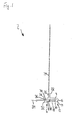
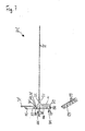
- Fig. 1 shows a not yet fixed first grout 2 in cross section.
- first plaster strip 2 has a horizontally extending base portion 4, in the left region, a web 22 projects forward away.
- a web 22 projects forward away.
- an upwardly extending reinforcing fabric 24 is secured by means of a weld 26.
- this is a welded joint, which has been created by ultrasonic welding by means of a separately supplied welding string, or a permanent bond.
- a first fixing area 6 and a second fixing area 12 are provided, which comprise a trough-shaped or semicircular adhesive strip receiving area 10 and 16 which faces rearward over a material bridge, in each of which a hotmelt adhesive strip 8 and 14 is received.
- an expansion strip 18 is arranged, which adheres with its upper side to the rear side of the base region 4 or is welded thereto, and whose rear side lies approximately at the level of the rear side of the hot-melt adhesive strips 8 and 14.
- a masking tape 20 extends from left to right over the hotmelt adhesive strip 8, over the expansion strip 18 and over the hotmelt adhesive strip 14.
- This masking tape 20 adheres with its left region to the underside of the hotmelt adhesive strip 8 and to its right region the underside of the hot-melt adhesive strip 14, and presses with its intermediate region intermediate the expansion strip 18 upwards and holds it in its compressed state.
- the expansion strip 18 is about 10 mm wide and in its compressed state has a thickness of about 2.5 mm.
- the expansion strip 18 has a delayed expansion, that is, after the removal of the cover strip 20, this expands to a maximum Ausdehnposition, which is at a level well below the undersides of the hot-melt adhesive strips 8 and 14.
- a Einputzschenkel 28 connects, which is plastered with and the outer left edge forms the edge for the top of the plaster layer.
- the top of Einputzschenkels 28, the left side of the web 22 and the transition region between them is provided with a channel profiling 30 to improve the adhesion of the plaster layer or the plaster layers on the first grout 2 by means of the thus enlarged surface.
- a soft cover lip 32 extends rearwardly approximately to the level of the back of the hotmelt adhesive strips 8 and 14 and the back of the expansion strip 18 or even further down.
- the cover lip 32 is slightly curved to the left rear and protects in the installed state of the plaster strip 2 against moisture and water.
- a strip-shaped protective tab 34 At the side end of Anputzschenkels 28 connects via a break-off material bridge lesser thickness 36, a strip-shaped protective tab 34, the front side is flat and the rear has a substantially perpendicular rearwardly projecting spacer web.
- the strip-shaped protective flap 34 has on its front side an adhesive layer to which a protective film, not shown here, can be glued.
- the cross section of the plaster strip 2 and the plaster strips described below is consistent over the entire length, so that the plaster strips can be easily prepared by extrusion.
- the covering lip 32 made of a softer material relative to the base material of the first plastering strip 2 and the adhesive strips can be coextruded.
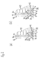
- Fig. 2 (a) shows the introduced in a transition between a thermal insulation 40 and a window frame 38 first grout 2 in horizontal section in a first state with a small gap extent
- Fig. 2 (b) shows them in horizontal section in a second state with large gap expansion.
- the window frame 38 can be provided, in particular, with a nanoparticle-coated surface, not shown separately, so that only adhesion but not permanent adhesion can be achieved.
- the first plaster strip 2 has been mounted on the window frame 38 after removal of the cover strip 20, in such a way that the hot-melt adhesive strips 8 and 14 adhere to the front of the window frame 38 or at least temporarily secure the plaster strip 2 thereto.
- the expansion strip 18 rests with its underside on the front side of the window frame 38.
- the heat insulation 38 has been fastened, in such a way that the right side of the web 22 of the first grout 2 and the adjacent thereto to the right front of the base portion 4 abut the corner region of the insulation 40.
- the gap 42 is reliably sealed by the base region 4 with the two hot-melt adhesive strips 8 and 14 and with the expansion strip 18 to the outside. This seal is still supported by the also applied to the window frame 38 cover lip 32.
- the gap has a width of 3 mm in the present exemplary embodiment.
- the area of the first plaster molding 2 between the right side of the web 22, which rests against the insulation 40 and the plastering edge of Anputzschenkels 28 together with the reinforcing fabric 24 and the channel profile 30 is plastered by means of a first layer of plaster 44 and a second layer of plaster 46 and thus reliable the thermal insulation 40 attached.
- the strip-shaped protective flap 34 has been separated after completion of the plastering work along the break-off material bridge 36, so that the strip-shaped protective flap 34 in Fig. 2 (a) no longer exists.
- the gap 42 has increased due to temperature-induced shrinkage of the thermal insulation 40, ie, the distance between thermal insulation 40 and window frame 38 has increased, so that the hot-melt adhesive strips 8 and 14 and the cover lip 32 no longer abut or adhere to the window frame 38 but rather that the hotmelt adhesive strips 8 and 14 and the covering lip 32 are at a distance from the window frame 38.
- the expansion strip 18, however, has expanded so that it compensates for the increase in the gap and that its underside still sealingly abuts the window frame 38 and provides a reliable seal of the space between the thermal insulation 40 and window frame 38.
- the Gap increased from 3 to 5 mm, and the expansion strip 18 has a thickness of about 4 mm, but still seals reliably against driving rain. It is possible to form the expansion strip 18 such that it experiences an expansion of more than 100% from a compressed state up to a maximum expansion state, for example from 2.5 mm to more than 5.0 mm, and at the same time is impact-proof. It is even possible to form the expansion strip 18 such that it experiences an expansion of more than 200% from a compressed state to a maximum expansion state, for example from 2.5 mm to more than 7.5 mm, and at the same time is impact-resistant ,
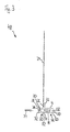
- Fig. 3 shows a not yet attached second grout bar 48 in cross section.
- the second plaster strip 48 corresponds with respect to most of its elements of the first plaster strip 2, and like elements are also identified by the same reference numerals.
- the second plaster strip 48 differs from the first plaster strip 2 in the formation of its fixing areas 50 and 56. These are formed as from the outer ends of the base portion 4 humped rear foot portions 52 and 58, on the flat underside adhesive tape strips 54 and 60 are attached , In an embodiment shown here, these can be double-sided adhesive tape strips, which are glued with their upper side to the flat undersides of the hump-shaped foot sections 52 and 58.
- the adhesive tape strip 20 is in both plaster strips 2 and 48 each a piece to the left on the left fixing region 6, 50 and a piece far to the right on the right fixing portion 12, 56 via.
- the thus projecting ends can be easily gripped to attach the cover strip 20 before installing the plaster strip 2, 48 in the gap 42 between the thermal insulation 40 and window frame 38.
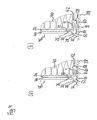
- Fig. 4 (a) shows the arranged in the transition between the thermal insulation 40 and the window frame 38 second plaster strip 48 in horizontal section in a first state with a small gap expansion and Fig. 4 (b) shows them in horizontal section in a second state with large gap expansion
- Fig. 4 (a) the hump-shaped foot sections 52, 58 are fixed to the window frame 38 by means of their adhesive tape strips 54 and 60.
- the gap between the thermal insulation 40 and the window frame 38 is reliably sealed off to the outside by the expansion strip 18, by the adhesive tape strips 54 and 60 and by the cover lip 32.
- the adhesive tape strips 54 and 60 and the cover lip 32 are arranged at a distance from the window frame 38.
- the expanded expansion strip 18 continues with its underside still on the window frame 38 and seals the gap between the thermal insulation 40 and window frame 38 reliably and permanently.
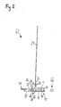
- Fig. 5 shows a not yet attached third plaster molding 62 in cross-section and a perspective view of a suction cup 66 used therein.
- the third plaster molding 62 corresponds to most of its elements of the first plaster molding 2, and like elements are also identified by the same reference numerals.
- the fixing regions 64 and 70 are designed as rows of suction cups 72 which are used in the third plastering strip 62 and which are respectively inserted into groove-shaped or semicircular suction cup receiving regions 68 and 72, in particular clipped into them.
- the masking tape 75 which covers the suction cups 66 and 72 and also holds the expansion strip 18 in its compressed state, extends to the left over the cover lip 32, the spacer web of the protective flap 34 over the end of the protective flap 34 to the front of the protective flap 34 and attached there by means of a bond, not shown.
- the cover tape 75 extends upwardly and is fixed to the right wall of the right suction cup receiving portion 74 by bonding.
- Fig. 6 (a) shows the arranged in the transition between the thermal insulation 40 and the window frame 38 third plaster strip 62 in horizontal section in a first state with a small gap expansion and Fig. 6 (b) shows them in horizontal section in a second state with large gap expansion.
- Fig. 7 shows a not yet attached fourth grout bar 76 in cross-section and a perspective view of a used therein suction belt 80 with integrated therein used suction cups 82nd
- the fourth plaster bar 76 corresponds to the third plaster bar 62 with respect to most of its elements, and like elements are also identified by the same reference numerals.
- the suction cups 82 and 90 are integrated into suction belts 80 and 88, and a first suction belt 80 is inserted into the semicircular suction channel receiving portion 84 of the first fixing portion 78 and also, a second suction belt 88 having suction cups 90 integrated therein is inserted into a semicircular suction channel receiving portion 92 of the second fixing portion 86.
- Fig. 8 (a) shows arranged in the transition between the insulation 40 and the window frame 38 fourth grout 76 in horizontal section in a first state with a small gap expansion; and Fig. 8 (b) shows them in horizontal section in a second state with large gap expansion.
- the fourth grout bar 76 is attached to the window frame 38 by means of the integrated suction cups 82.
- the sealing effect is achieved by the expansion strip 18, by the suction belts 80 and 88, which also bear tightly against the window frame 38, and reached by the cover lip 32.
- Fig. 9 shows a not yet fixed fifth grout 94 in cross section.
- the fifth plaster bar 94 corresponds to most of its elements of the second plaster bar 48, and like elements are also identified by the same reference numerals.
- the fifth plaster strip 94 differs from the second plaster strip 48 in the formation of its fixing regions 96 and 102.
- the fixing regions 96 and 102 have a staple-shaped formation or essentially the shape of an L or an inverted L, and they extend from the left or right end of the base portion 4 to the rear.
- Double-sided adhesive tape strips 100 and 106 are applied to the rear sides of the straight foot sections 98 and 104.
- a cover strip 20 is provided which adheres to the adhesive tape strips 100 and 106 and which holds the expansion strip 18 arranged therebetween in its compressed state.
- Fig. 10 (a) shows the arranged in the transition between the thermal insulation 40 and the window frame 38 fifth grout 94 in horizontal section in a first state with a small gap expansion; and Fig. 8 (b) shows them in horizontal section in a second state with large gap expansion.
- the presentation largely corresponds to the representation in Fig. 4
- the staple-shaped foot portions 98 and 104 are fixed by means of their adhesive tape strips 100 and 106 on the window frame 38.
Landscapes
- Engineering & Computer Science (AREA)
- Architecture (AREA)
- Civil Engineering (AREA)
- Structural Engineering (AREA)
- Mechanical Engineering (AREA)
- Building Environments (AREA)
- Adhesives Or Adhesive Processes (AREA)
Abstract
Description
Die Erfindung betrifft eine einteilige Abdicht- oder Anputzleiste zur Platzierung an einem Übergang zwischen einem Bauteil eines Gebäudes und einer Wärmedämmung oder einer Putzschicht, einen solchen Übergang mit einer derartigen einteiligen Abdicht- oder Anputzleiste sowie ein Verfahren zum Anbringen einer einteiligen Abdicht- oder Anputzleiste an einem solchen Übergang.The invention relates to a one-piece sealing or plaster molding for placement at a transition between a component of a building and a thermal insulation or a plaster layer, such a transition with such a one-piece Abdicht- or plaster molding and a method for attaching a one-piece sealing or plaster molding on a such transition.
Im Stand der Technik sind Anputzleisten bekannt, die längs des Randes eines Fenster- oder Türstocks an den Fenster- oder Türstock angeklebt werden. Eine solche Anputzleiste ist aus der
Moderne Fenster- oder Türrahmen sind nun häufig mit einer Nanobeschichtung auf ihrer Oberfläche versehen. Eine solche Nanobeschichtung weist Nanopartikel auf, und aufgrund der Oberflächenstruktur einer solchen Nanobeschichtung haftet an den Fenster- und Türrahmen nur wenig Schmutz an, die Fenster- oder Türrahmen müssen also deutlich seltener gereinigt werden als herkömmliche Fenster- oder Türrahmen. Damit einher geht allerdings das Problem, dass sich bei den im Stand der Technik bekannten Anputzleisten auf die Dauer häufig Ablösungen zeigen, und Feuchtigkeit oder Wasser in den Zwischenraum zwischen Fenster- oder Türrahmen und Wärmedämmung eintritt. Dies führt zu Schimmelbildung und zu erhöhten Heizkosten.Modern window or door frames are now often provided with a nano-coating on their surface. Such a nano-coating has nanoparticles, and due to the surface structure of such a nano-coating adheres to the window and door frames little dirt, the window or door frames must be cleaned so much less common than conventional window or door frames. However, this is accompanied by the problem that often show detachments in the known in the prior art plaster strips, and moisture or water enters the space between the window or door frame and insulation. This leads to mold growth and increased heating costs.
Es ist daher eine Aufgabe der vorliegenden Erfindung, eine Abdicht- oder Anputzleiste sowie einen Übergang zwischen einem Bauteil eines Gebäudes und einer Wärmedämmung oder einer Putzschicht anzugeben, mit denen eine zuverlässige und dauerhafte Abdichtungswirkung auch bei Gebäude-Bauteilen gegeben ist, deren Oberfläche keine dauerhafte Verklebung zulässt. Es soll auch ein einfach durchführbares Verfahren zum Anbringen einer solchen Abdicht- oder Anputzleiste an einem solchen Übergang angegeben werden.It is therefore an object of the present invention to provide a sealing or plastering strip and a transition between a component of a building and a thermal insulation or a plaster layer with which a reliable and durable sealing effect is also given in building components whose surface no permanent bonding allows. It is also an easy-to-carry method for attaching such a sealing or plaster molding to be given at such a transition.
Diese Aufgaben werden durch den Gegenstand der unabhängigen Ansprüche gelöst. Vorteilhafte Weiterbildungen ergeben sich aus den abhängigen Ansprüchen.These objects are achieved by the subject matter of the independent claims. Advantageous developments emerge from the dependent claims.
Eine erfindungsgemäße einteilige Abdicht- oder Anputzleiste, die an einem Übergang, insbesondere in einem Spalt eines solchen Übergangs zwischen einem Bauteil eines Gebäudes und einer Wärmedämmung oder einer Putzschicht anzubringen ist, umfasst einen Basisbereich, der an seiner Rückseite einen sich längs der Abdicht- oder Anputzleiste erstreckenden Expansionsstreifen mit verzögerter Expansion zur dichtenden Anlage der Abdicht- oder Anputzleiste an dem Gebäude-Bauteil sowie wenigstens ein daneben angeordnetes Befestigungsmittel zur wenigstens vorübergehenden Befestigung der Abdicht- oder Anputzleiste an dem Gebäude-Bauteil aufweist. Der Expansionsstreifen wird durch ein Haltemittel in einem zusammengepressten Zustand gehalten, und er ist derart beschaffen bzw. verfügt über eine derartige Dehnreserve, dass er sich nach dem Lösen des Haltemittels in eine maximale Ausdehnposition ausdehnt, die weiter von der Rückseite des Basisbereichs entfernt ist als die Unterseite des Befestigungsmittels, um so auch bei einem vergrößerten Abstand zwischen dem Gebäude-Bauteil und der Wärmedämmung oder der Putzschicht eine dichtende Anlage an dem Gebäude-Bauteil sicherzustellen. Wenigstens ein Teil der Vorderseite des Basisbereichs ist zur Anlage an der Wärmedämmung oder der Putzschicht bestimmt.A one-piece sealing or plastering strip according to the invention, which is to be attached to a transition, in particular in a gap of such a transition between a component of a building and a thermal insulation or a plaster layer, comprises a base region, which at its back along the sealing or grout extending expansion strip with delayed expansion for sealing contact of the sealing or plastering strip on the building component and at least one adjacently arranged fastening means for at least temporary attachment of the sealing or plaster strip on the building component. The expansion strip is held in a compressed state by a holding means, and has such a stretchable reserve that it expands after releasing the holding means to a maximum expansion position farther away from the back of the base region than the expansion bar Bottom of the fastener, so as to ensure a sealing contact with the building component even with an increased distance between the building component and the thermal insulation or the plaster layer. At least a part of the front of the base area is intended for contact with the thermal insulation or the plaster layer.
Es ist möglich, die erfindungsgemäße Leiste nur in dem Übergang zwischen dem Gebäude-Bauteil und der Wärmedämmung oder der Putzschicht anzuordnen, ohne sie durch Ein- oder Anputzen an der Wärmedämmung zu befestigen. Eine solche Leiste wird nachfolgend als Abdichtleiste bezeichnet. Wenn die erfindungsgemäße Leiste zusätzlich an der Wärmedämmung an- oder eingeputzt wird, so wird nachfolgend von Anputzleiste gesprochen.It is possible to arrange the strip according to the invention only in the transition between the building component and the thermal insulation or the plaster layer, without attaching them by plastering or plastering on the insulation. Such a strip is referred to below as a sealing strip. If the strip according to the invention is additionally plastered on or plastered on the thermal insulation, then it is spoken of plastering strip.
Wenn nachfolgend von Gebäude-Bauteilen die Rede ist, so sind davon alle gängigen Gebäude-Bauteile umfasst, die normalerweise an einer Wärmedämmung anliegen können, insbesondere Fenster- oder Türrahmen, Balken, austretende Balken, Fensterbänke, Metallverbindungen oder Lisenen.When reference is made below to building components, they include all standard building components that can normally rest against thermal insulation, in particular window or door frames, beams, escaping beams, window sills, metal connections or pilaster strips.
Sowohl die Wärmedämmung als auch die Putzschicht können an der Außenseite des Gebäudes an das Gebäude-Bauteil angrenzen. Alternativ dazu können sowohl die Wärmedämmung als auch die Putzschicht auf der Gebäude-Innenseite angeordnet sein.Both the thermal insulation and the plaster layer can adjoin the building component on the outside of the building. Alternatively, both the thermal insulation and the plaster layer may be disposed on the inside of the building.
Gemäß einer der Erfindung zugrunde liegenden Erkenntnis ändert sich im Laufe der Zeit der Abstand zwischen dem Gebäude-Bauteil und der Wärmedämmung oder der Putzschicht durch auftretende Temperaturschwankungen, und dieser Effekt ist besonders stark ausgeprägt, wenn der Übergang einer direkten Sonneneinstrahlung ausgesetzt ist. Bei einer Vergrößerung des Abstands zwischen dem Gebäude-Bauteil und der Wärmedämmung oder der Putzschicht löst sich oft das Befestigungsmittel, insbesondere das Klebeband, von dem Gebäude-Bauteil, wobei dieser Effekt besonders stark ausgeprägt ist, wenn das Gebäude-Bauteil eine Oberfläche aufweist, an der eine dauerhafte Verklebung nicht möglich ist, beispielsweise eine Nanopartikel-Oberfläche oder eine herkömmliche Polyethylen-Oberfläche, Polypropylen-Oberfläche und/oder silkonisierte Oberfläche.According to one of the invention underlying knowledge changes over time, the distance between the building component and the thermal insulation or the plaster layer by temperature fluctuations occurring, and this effect is particularly pronounced when the transition is exposed to direct sunlight. With an increase in the distance between the building component and the thermal insulation or the plaster layer often solves the fastener, in particular the tape, of the building component, this effect is particularly pronounced when the building component has a surface on a permanent bonding is not possible, for example a nanoparticle surface or a conventional polyethylene surface, polypropylene surface and / or silicided surface.
Aufgrund eines Grundgedankens der vorliegenden Erfindung kann durch das erfindungsgemäße Vorsehen eines Expansionsstreifens zur dichtenden Anlage der Abdicht- oder Anputzleiste an dem Gebäude-Bauteil, der über eine Dehnreserve verfügt, sowie wenigstens eines daneben angeordneten Befestigungsmittels zur wenigstens vorübergehenden Befestigung der Abdicht- oder Anputzleiste an dem Gebäude-Bauteil eine dauerhafte Abdichtung des Übergangs zwischen dem Gebäude-Bauteil und der Wärmedämmung oder der Putzschicht gewährleistet werden, auch wenn temperaturbedingte Abstandsänderungen zwischen dem Gebäude-Bauteil und der Wärmedämmung oder der Putzschicht auftreten, und auch wenn das Gebäude-Bauteil eine Oberfläche aufweist, auf der nur eine vorübergehende Anhaftung, nicht jedoch eine dauerhafte Verklebung möglich ist.Due to a basic idea of the present invention can be provided by the inventive provision of an expansion strip for sealing contact the sealing or plaster molding on the building component, which has a Dehnreserve, and at least one adjacently arranged fastening means for at least temporary attachment of the sealing or plastering strip on the Building component a permanent sealing of the transition between the building component and the thermal insulation or the plaster layer are guaranteed, even if temperature-related changes in distance between the building component and the thermal insulation or the plaster layer occur, and even if the building component has a surface, on which only a temporary adhesion, but not a permanent bonding is possible.
Bei der erfindungsgemäßen Abdicht- oder Anputzleiste reicht es aus, wenn das Befestigungsmittel nur vorübergehend während der Montage der Abdicht- oder Anputzleiste und, falls eingeputzt wird, des Einputzens an dem Gebäude-Bauteil anhaftet und somit befestigt ist, und dies ist mittels des erfindungsgemäßen Befestigungsmittels möglich. Das Befestigungsmittel muss nur eine vorübergehende Fixierung der Abdicht- oder Anputzleiste während der Montage und während dem Einputzen sicherstellen. In Kurzform kann dies als Montagehalt bezeichnet werden. Für die Abdichtungsfunktion wird das Befestigungsmittel grundsätzlich nicht benötigt.In the case of the sealing or plastering strip according to the invention, it is sufficient if the fastening means is only temporarily adhered to the building component during installation of the sealing or plastering strip and, if plastered, plastering, and this is secured by means of the fastening means according to the invention possible. The fastener must ensure only a temporary fixation of the sealing or plaster molding during assembly and during plastering. In short, this can be referred to as mounting stop. For the sealing function, the fastening means is basically not needed.
Das Befestigungsmittel kann sich längs der Abdicht- oder Anputzleiste erstrecken und durchgehend ausgebildet sein. Ebenso ist auch eine punktförmige oder unterbrochene Ausbildung des Befestigungsmittels möglich.The fastening means may extend along the sealing or plastering strip and be formed continuously. Likewise, a punctiform or interrupted formation of the fastener is possible.
Nach der Montage der Abdicht- oder Anputzleiste und, falls eingeputzt wird, dem Einputzen übernimmt der Expansionsstreifen die Abdichtwirkung, indem er sich aufgrund des vor der Montage der Abdicht- oder Anputzleiste gelösten Haltemittels ausdehnt und dichtend an dem Gebäude-Bauteil anlegt, ohne jedoch mit diesem eine Haftung oder Verklebung einzugehen. Da dieser Expansionsstreifen über eine Dehnreserve verfügt, kann dieser Abstandsänderungen zwischen dem Gebäude-Bauteil und der Wärmedämmung oder der Putzschicht "mitmachen", d.h. bei einer Vergrößerung des Abstands zwischen dem Gebäude-Bauteil und der Wärmedämmung oder der Putzschicht dehnt sich auch der Expansionsstreifen weiter aus, so dass er auch weiterhin dichtend an dem Gebäude-Bauteil anliegt, und bei einer Verkleinerung des Abstands zwischen dem Gebäude-Bauteil und der Wärmedämmung oder der Putzschicht wird der Expansionsstreifen wieder ein Stück weit zusammengepresst, und er liegt weiterhin abdichtend an dem Gebäude-Bauteil an. Die durch den Expansionsstreifen bereitgestellte Abdichtwirkung reicht aus, um ein Eindringen von Feuchtigkeit oder Wasser in den Zwischenraum zwischen Gebäude-Bauteil und Wärmedämmung oder Putzschicht dauerhaft zu verhindern.After installation of the sealing or plastering strip and, if plastered, the plastering the expansion strip takes over the sealing effect by expanding due to the dissolved prior to mounting the sealing or plaster molding holding means and sealingly applies to the building component, but without to take this a liability or bonding. Since this expansion strip has an expansion reserve, this change in distance between the building component and the thermal insulation or the plaster layer can "join in", i. with an increase in the distance between the building component and the thermal insulation or plaster layer and the expansion strip continues to expand, so that it continues to seal against the building component, and with a reduction in the distance between the building component and the Thermal insulation or the plaster layer of the expansion strip is again pressed together a piece, and he continues to lie sealingly on the building component. The sealing effect provided by the expansion strip is sufficient to permanently prevent ingress of moisture or water into the space between the building component and thermal insulation or plaster layer.
Die Dehnreserve des Expansionsstreifens sollte dabei so bemessen sein, dass sich der Expansionsstreifen weiter ausdehnt, als es der maximalen Breite des Spalts bzw. der Fuge entspricht, und dass der Expansionsstreifen bei einer solchen Ausdehnung trotzdem schlagregendicht ist. Die Ausdehnungsänderung des Expansionsstreifens vom zusammengepressten Zustand bis zur maximalen schlagregendichten Ausdehnposition beträgt vorteilhafterweise mindestens 25 %, kann jedoch auch deutlich darüber liegen, um größere Spalt- bzw. Fugenausdehnungen mitmachen zu können.The expansion reserve of the expansion strip should be dimensioned so that the expansion strip expands further than corresponds to the maximum width of the gap or the joint, and that the expansion strip is nevertheless impact rainproof in such an expansion. The expansion change of the expansion strip from the compressed state to the maximum impact-proof Ausdehnposition is advantageously at least 25%, but can also be significantly higher in order to join larger gap or joint expansions.
Der Expansionsstreifen ist Abdicht- oder Anputzleisten-seitig an dem Basisbereich der Abdicht- oder Anputzleiste befestigt. Diese Befestigung kann auf beliebige Art erfolgen, beispielsweise durch Verklebung oder durch eine Klemmbefestigung.The expansion strip is attached to the base area of the sealing or plastering strip on the sealing or plaster molding side. This attachment can be done in any way, for example by gluing or by a clamp.
Bei dem Expansionsband bzw. Expansionsstreifen kann es sich um ein expandierendes Schaumstoffklebeband handeln. Durch die Auswahl des Expansionsstreifens, insbesondere durch die Wahl der Dehnreserve des Expansionsstreifens wird die maximale Ausdehnposition des Expansionsstreifens festgelegt, d.h. der maximale Abstand zwischen Gebäude-Bauteil und Wärmedämmung oder Putzschicht, bis zu dem eine sichere Abdichtung gewährleistet ist. In der Praxis ist stets ein Expansionsstreifen mit einer ausreichenden Dehnreserve vorzusehen, der auch in der Lage ist, den sich in der Praxis maximal ergebenden Abstand zwischen Gebäude-Bauteil und Wärmedämmung oder Putzschicht abzudichten und der alle Bewegungen aufnehmen kann.The expansion band or expansion strip can be an expanding foam adhesive tape. By selecting the expansion strip, in particular by selecting the expansion reserve of the expansion strip, the maximum expansion position of the expansion strip is determined, ie the maximum distance between building component and thermal insulation or plaster layer, to which a secure seal is ensured. In practice, always provide an expansion strip with a sufficient expansion reserve, which is also able to seal in practice the maximum resulting distance between the building component and thermal insulation or plaster layer and can absorb all movements.
Durch die einteilige Ausführung der Abdicht- oder Anputzleiste ist eine besonders kostengünstige Herstellung und einfache Anbringung der Abdicht- oder Anputzleiste auf der Baustelle möglich.Due to the one-piece design of the sealing or plaster molding, a particularly cost-effective production and easy attachment of the sealing or plastering strip on the construction site is possible.
Gemäß einer ersten Ausführungsform der Erfindung ist das Haltemittel als Abdeckband oder als Verschlussklappe ausgebildet. Dies ermöglicht ein besonders einfaches Lösen des Haltemittels vor dem Anbringen der Abdicht- oder Anputzleiste an dem Übergang zwischen Gebäude-Bauteil und Wärmedämmung oder Putzschicht.According to a first embodiment of the invention, the holding means is designed as a cover strip or as a closure flap. This allows a particularly simple release of the retaining means before attaching the sealing or plastering strip at the transition between building component and thermal insulation or plaster layer.
Gemäß einer weiteren Ausführungsform ist das Befestigungsmittel als Klebstoffstreifen, insbesondere als Heißkleber-/Hotmelt-Klebstoff-Streifen ausgebildet. Ein derartiger Klebstoffstreifen stellt eine sichere Anhaftung der Abdicht- oder Anputzleiste an dem Gebäude-Bauteil während der Montage und dem Einputzen sicher. Der Klebstoffstreifen wird vorzugsweise bei der Herstellung der einteiligen Abdicht- oder Anputzleiste aufextrudiert. Wenn der Klebstoffstreifen in einer länglichen Vertiefung an der Rückseite des Basisbereichs platziert ist, ist dieser besonders zuverlässig mit der Abdicht- oder Anputzleiste verbunden, seine Position ist genau festgelegt, und ein seitliches Wandern des Klebstoffstreifens wird vemieden.According to a further embodiment, the fastening means is designed as an adhesive strip, in particular as a hot melt adhesive / hot melt adhesive strip. Such an adhesive strip ensures secure adhesion of the sealing or plastering strip to the building component during assembly and plastering. The adhesive strip is preferably extruded in the production of the one-piece sealing or plastering strip. When the adhesive strip is placed in an oblong depression at the back of the base region, it is particularly reliably connected to the sealing or plastering strip, its position is precisely defined, and lateral migration of the adhesive strip is avoided.
In einer alternativen Ausführungsform der Erfindung ist das Befestigungsmittel als Klebebandstreifen, insbesondere als doppelseitig klebender Klebebandstreifen ausgebildet. Mit der Unterseite haftet die Abdicht- oder Anputzleiste an dem Gebäude-Bauteil an, und stellt so eine wenigstens vorübergehende Befestigung sicher. Der Klebebandstreifen kann vorzugsweise Abdicht- oder Anputzleistenseitig mit einem nach hinten stehenden Fußabschnitt des Basisbereichs verklebt sein. Dieser Fußabschnitt kann ein integraler Bestandteil des Basisbereichs sein.In an alternative embodiment of the invention, the fastening means is designed as an adhesive tape strip, in particular as double-sided adhesive tape strip. With the underside, the sealing or plaster molding adheres to the building component, thus ensuring at least temporary attachment. The adhesive tape strip can preferably be glued to the sealing or scraper strip side with a foot portion of the base region standing to the rear. This foot section may be an integral part of the base section.
Sowohl bei der Ausbildung des Befestigungsmittels als Klebstoffstreifen als auch bei der Ausbildung des Befestigungsmittels als Klebebandstreifen wird, solange das Befestigungsmittel an dem Gebäude-Bauteil anhaftet, noch eine zusätzliche Abdichtungswirkung neben der durch den Expansionsstreifen bereitgestellten Abdichtungswirkung bereitgestellt.Both in the formation of the fastener as an adhesive strip and in the formation of the fastener as a tape strip, as long as the fastener adheres to the building component, an additional sealing effect is provided in addition to the sealing effect provided by the expansion strip.
In einer alternativen Ausführungsform der Erfindung nimmt das Befestigungsmittel eine streifenförmige Anordnung von Saugnäpfen auf. Diese können in einem Saugband integriert sein, was deren Handhabbarkeit und Befestigung an der Abdicht- oder Anputzleiste vereinfacht. Besonders gut sind die Saugnäpfe und/oder das Saugband an der Abdicht- oder Anputzleiste anzubringen, wenn der Basisbereich an seiner Rückseite eine längliche Vertiefung aufweist, in der die Saugnäpfe und/oder das Saugband aufgenommen sind/ist. Dadurch kann die Abdicht- oder Anputzleiste einfach und zuverlässig mit Saugnäpfen und/oder dem Saugband ausgestattet werden, die Saugnäpfe und/oder das Saugband werden einfach in die längliche Vertiefung eingesetzt, insbesondere eingeklipst. In der einfachsten Ausführung können nur ein oder zwei Saugnäpfe vorgesehen sein, um einen Montagehalt sicherzustellen.In an alternative embodiment of the invention, the attachment means receives a strip-shaped arrangement of suction cups. These can be integrated in a suction belt, which simplifies their handling and attachment to the sealing or plaster molding. Particularly well, the suction cups and / or the suction belt to be attached to the sealing or plaster molding when the base portion has on its back an elongated recess in which the suction cups and / or the suction belt is / is received. Thereby, the sealing or plastering strip can be easily and reliably equipped with suction cups and / or the suction belt, the suction cups and / or the suction belt are simply inserted into the elongated recess, in particular clipped. In the simplest embodiment, only one or two suction cups can be provided to ensure a mounting stop.
Alternativ zu den hier beispielhaft angegebenen Befestigungsmitteln können auch andere Befestigungsmittel zum Einsatz kommen.As an alternative to the fastening means exemplified here, other fastening means may also be used.
Gemäß einer besonders zuverlässigen Ausführungsform der Erfindung umfasst die Abdicht- oder Anputzleiste zwei Befestigungsmittel an der Rückseite des Basisbereichs, die den Expansionsstreifen einschließen. Durch das Vorsehen von zwei Befestigungsmitteln kann eine besonders zuverlässige vorübergehende Befestigung der Abdicht- oder Anputzleiste während der Montage und dem Einputzen bereitgestellt werden.According to a particularly reliable embodiment of the invention, the sealing or plastering strip comprises two fastening means on the rear side of the base region which enclose the expansion strip. By providing two fasteners, a particularly reliable temporary attachment of the sealing or plaster molding during assembly and plastering can be provided.
Durch diese zwei Befestigungsmittel, von denen eines seitlich des Expansionsstreifens in Richtung zu dem Zwischenraum zwischen Gebäude-Bauteil und Wärmedämmung oder Putzschicht hin und das zweite Befestigungsmittel in Richtung von dem Zwischenraum zwischen Gebäude-Bauteil und Befestigungsmittel weg vorgesehen sind, ergibt sich zusätzlich noch eine dadurch bereitgestellte unterstützende Abdichtwirkung, solange die Befestigungsmittel an dem Gebäude-Bauteil anhaften oder zumindest an ihm anliegen.These two fastening means, one of which is provided laterally of the expansion strip in the direction of the gap between the building component and thermal insulation or plaster layer and the second fastening means in the direction of the space between the building component and fastener away, there is additionally still a result provided supporting sealing effect, as long as the fastening means adhere to the building component or at least abut him.
In einer weiteren Ausführungsform der Erfindung sind im Lieferzustand der Abdicht- oder Anputzleiste die Befestigungsmittel und der Expansionsstreifen an der der Rückseite des Basisbereichs fortgewandten Seite von einem Abdeckband bedeckt, um dadurch ein vorzeitiges unerwünschtes Anhaften der Befestigungsmittel zu verhindern. Durch Vorsehen eines gemeinsamen Abdeckbandes oder Abdeckstreifens für die Befestigungsmittel und den Expansionsstreifen ergibt sich eine verbesserte Handhabbarkeit, und die Vorbereitung der Abdicht- oder Anputzleiste für die Montage kann durch Abziehen eines einzigen Abdeckbands auf einfache Weise durchgeführt werden.In a further embodiment of the invention, in the delivery state of the sealing or plastering strip, the fastening means and the expansion strip are covered by a masking tape on the side facing away from the back of the base region, thereby preventing premature undesired attachment of the fastening means. By providing a common masking tape or covering strip for the fastening means and the expansion strip results in improved handling, and the preparation of the sealing or plaster molding for assembly can be carried out easily by peeling off a single masking tape.
Besonders vorteilhaft ist es, wenn das Abdeckband zugleich auch das Haltemittel bildet, das den Expansionsstreifen in seinem zusammengepressten Zustand hält. Auf ein zusätzliches Haltemittel kann so verzichtet werden.It is particularly advantageous if the cover strip at the same time also forms the holding means which holds the expansion strip in its compressed state. An additional holding means can be dispensed with.
Gemäß einer weiteren Ausführungsform der Erfindung ist das Abdeckband durch Haftungswirkung an den Befestigungsmitteln fixiert. Alternativ dazu ist es möglich, dass das Abdeckband mit wenigstens einem seiner Endbereiche an einer anderen Stelle der Abdicht- oder Anputzleiste, insbesondere an deren Seite oder an deren Vorderseite lösbar befestigt, insbesondere verklebt ist.According to a further embodiment of the invention, the masking tape is fixed by adhesion to the fastening means. Alternatively, it is possible that the cover strip with at least one of its end portions at a different location of the sealing or plaster strip, in particular on its side or on the front detachably attached, in particular glued.
Gemäß einer weiteren Ausführungsform der Erfindung ist die Leiste als Anputzleiste ausgebildet und wird somit durch An- oder Einputzen an der Wärmedämmung oder der Putzschicht befestigt. Hierfür weist sie einen nach vorne wegragenden, sich längs der Anputzleiste erstreckenden Steg auf.According to a further embodiment of the invention, the strip is designed as a plaster strip and is thus fixed by plastering or plastering on the thermal insulation or the plaster layer. For this purpose, it has a projecting forward, extending along the plastering strip web.
Gemäß einer weiteren Ausführungsform der Erfindung ist an der Anputzleiste, und insbesondere an deren Steg ein in den Putz einzubettendes Armierungsgewebe befestigt. Durch ein solches Armierungsgewebe werden Rissbildungen in der Putzschicht sicher vermieden. Das Armierungsgewebe besteht in den meisten Fällen aus einem Glasgittergewebe.According to a further embodiment of the invention, a reinforcing fabric to be embedded in the plaster is attached to the plastering strip, and in particular to its web. By such a reinforcing fabric cracks in the plaster layer are safely avoided. The reinforcement fabric consists in most cases of a glass mesh fabric.
Gemäß einer weiteren Ausführungsform der Erfindung setzt an dem Basisbereich ein im eingebauten Zustand der Anputzleiste in Richtung weg von dem Zwischenraum zwischen Gebäude-Bauteil und Wärmedämmung oder Putzschicht stehender Einputzschenkel an, der mit eingeputzt wird und die Kante für die äußere Putzschicht bildet.According to a further embodiment of the invention sets to the base area in the installed state of the plaster strip in the direction away from the gap between the building component and thermal insulation or plaster layer standing Einputzschenkel, which is plastered with and forms the edge for the outer plaster layer.
An der Rückseite des Einputzschenkels kann eine flexible, insbesondere gekrümmte Abdecklippe vorgesehen sein, um bei normalem Abstand zwischen Gebäude-Bauteil und Wärmedämmung oder Putzschicht eine zusätzliche Schutzwirkung nach außen zu gewährleisten.At the back of Einputzschenkels a flexible, in particular curved cover lip may be provided to ensure an additional protective effect to the outside at a normal distance between the building component and thermal insulation or plaster layer.
Gemäß einer weiteren Ausführungsform der Erfindung ist eine streifenförmige Schutzlasche vorgesehen, die über eine Abbrech-Materialbrücke geringerer Dicke mit dem Basisbereich oder mit dem Einputzschenkel zusammenhängt. An einer solchen streifenförmigen Schutzlasche wird die Folie aufgeklebt, welche die Fenster- bzw. Türfläche überspannt, und nach dem Aufbringen der Putzschicht kann diese Schutzlasche einfach abgetrennt und entfernt werden.According to a further embodiment of the invention, a strip-shaped protective tab is provided, which is connected via a break-off material bridge of lesser thickness with the base area or with the plastering leg. On such a strip-like protective tab, the film is glued, which the window or door surface spans, and after the application of the plaster layer, this protective tab can be easily separated and removed.
Gemäß einer weiteren Ausführungsform der Erfindung ist wenigstens eines der Befestigungsmittel an der streifenförmigen Schutzlasche vorgesehen und wird, nach erfolgter Montage der Anputzleiste, zusammen mit dieser entfernt.According to a further embodiment of the invention, at least one of the fastening means is provided on the strip-shaped protective flap and is, after the installation of the plaster strip, removed together with this.
Die erfindungsgemäße Abdicht- oder Anputzleiste ist vorzugsweise aus einem geeigneten Kunststoff durch Extrusion hergestellt.The sealing or plastering strip according to the invention is preferably made of a suitable plastic by extrusion.
Die Erfindung betrifft auch einen Übergang zwischen einem Gebäude-Bauteil und einer Wärmedämmung oder einer Putzschicht mit einem dort vorhandenen Spalt, in den eine Abdicht- oder Anputzleiste der oben beschriebenen Art derart eingebracht ist, dass der Steg und/oder wenigstens ein Teil der Vorderseite des Basisbereichs an der Wärmedämmung oder der Putzschicht anliegen.The invention also relates to a transition between a building component and a thermal insulation or a plaster layer with a gap there, in which a sealing or plastering strip of the type described above is introduced such that the web and / or at least a portion of the front of Base area to the thermal insulation or the plaster layer.
Im Einbauzustand und bei normaler Spaltabmessung befestigt das wenigstens eine Befestigungsmittel die Abdicht- oder Anputzleiste wenigstens vorübergehend an dem Gebäude-Bauteil oder liegt abdichtend oder haftend an diesem an, und der Expansionsstreifen liegt abdichtend an dem Gebäude-Bauteil an. Bei einem vergrößerten Spalt, beispielsweise infolge von Temperaturschwankungen, ist das wenigstens eine Befestigungsmittel von dem Gebäude-Bauteil gelöst und seine Unterseite befindet sich in einem Abstand zu diesem. Gleichzeitig hat sich der Expansionsstreifen aufgrund seiner Dehnreserve etwas weiter ausgedehnt und liegt weiterhin abdichtend an dem Gebäude-Bauteil an.In the installed state and with a normal gap dimension, the at least one fastening means at least temporarily fixes the sealing or plastering strip to the building component or is sealingly or adhesively attached thereto, and the expansion strip is sealingly applied to the building component. In an enlarged gap, for example as a result of temperature fluctuations, the at least one fastening means is released from the building component and its underside is at a distance therefrom. At the same time, the expansion strip has expanded somewhat further due to its expansion reserve and continues to be sealing against the building component.
Durch den erfindungsgemäßen Übergang zwischen Gebäude-Bauteil und Wärmedämmung oder Putzschicht wird somit eine zuverlässige und dauerhafte Abdichtung des Spalt des Übergangs unabhängig von der Beschaffenheit der Oberfläche des Gebäude-Bauteils und unabhängig von den temperaturbedingten Abstandsänderungen zwischen Gebäude-Bauteil und Wärmedämmung oder Putzschicht bereitgestellt.The inventive transition between building component and thermal insulation or plaster layer thus a reliable and permanent sealing of the gap of the transition is provided regardless of the nature of the surface of the building component and regardless of the temperature-related changes in distance between building component and thermal insulation or plaster layer.
Die Erfindung betrifft auch ein Verfahren zum Anbringen einer einteiligen Leiste, insbesondere einer Abdicht- oder Anputzleiste der oben beschriebenen Art, in einen Spalt eines Übergangs zwischen einem Gebäude-Bauteil und einer Wärmedämmung. Dabei wird zunächst das Haltemittel des Expansionsstreifens gelöst, dann wird die Leiste derart an dem Gebäude-Bauteil angebracht, dass das wenigstens eine Befestigungsmittel sie wenigstens vorübergehend an dem Gebäude-Bauteil befestigt. Dann wird die Wärmedämmung derart an dem Mauerwerk oder dgl. befestigt, dass deren Eckbereich an dem Steg der Leiste und/oder an wenigstens einem Teil der Vorderseite des Basisbereichs der Leiste anliegt/anliegen.The invention also relates to a method for attaching a one-piece strip, in particular a sealing or plastering strip of the type described above, in a gap of a transition between a building component and a thermal insulation. In this case, first the holding means of the expansion strip is released, then the bar is attached to the building component such that the at least one fastening means at least temporarily to the building component attached. Then, the thermal insulation is fixed to the masonry or the like., That their corner region on the web of the bar and / or at least a part of the front of the base portion of the bar rests / abut.
Wenn es sich bei der Leiste um eine Anputzleiste handelt, wird/werden der Steg sowie ggf. das Armierungsgewebe und/oder der Einputzschenkel anschließend noch eingeputzt.If the strip is a plastering strip, the bar and / or the reinforcement fabric and / or the plastering leg is / are then plastered.
Das Auslösen des Expansionsstreifens erfolgt damit erfindungsgemäß vor dem Anbringen der Leiste an dem Übergang zwischen Gebäude-Bauteil und Wärmedämmung, und das Einbringen der Leiste erfolgt unmittelbar nach dem Auslösen der Expansion des Expansionsstreifens.The triggering of the expansion strip is thus according to the invention before attaching the bar at the transition between the building component and thermal insulation, and the introduction of the bar takes place immediately after the triggering of expansion of the expansion strip.
Das erfindungsgemäße Verfahren ist einfach ausführbar und ergibt als Arbeitsergebnis eine zuverlässige und dauerhafte Abdichtung zwischen Fenster- und Türrahmen und der Wärmedämmung bzw. dem Wärmedämm-Verbundsystem. Die oben vorrichtungsmäßig angegebenen Ausgestaltungen können auch in verfahrensmäßiger Entsprechung bei dem erfindungsgemäßen Verfahren zum Anbringen einer einteiligen Abdicht- oder Anputzleiste zum Einsatz kommen, diese werden, um Wiederholungen zu vermeiden, nicht noch einmal im einzelnen beschrieben. Es ergeben sich dabei die gleichen, bereits oben mit Bezug auf die Abdicht- oder Anputzleiste beschriebenen Vorteile.The inventive method is simple to perform and results in a reliable and durable seal between window and door frame and the thermal insulation or the thermal insulation composite system as a result of work. The embodiments given above in terms of apparatus can also be used in procedural correspondence with the method according to the invention for attaching a one-piece sealing or plastering strip, these are not described again in detail in order to avoid repetition. This results in the same advantages already described above with respect to the sealing or plastering strip.
Die Erfindung ist nachfolgend anhand von Ausführungsbeispielen mit Bezug auf die beiliegenden Figuren näher erläutert.
-
Fig. 1 zeigt eine noch nicht befestigte erste Anputzleiste gemäß einem ersten Ausführungsbeispiel der Erfindung im Querschnitt; -
Fig. 2(a) zeigt die in einem Übergang zwischen einer Wärmedämmung und einem Fensterrahmen angeordnete Anputzleiste ausFig. 1 im Horizontalschnitt in einem ersten Zustand mit geringer Spaltausdehnung; -
Fig. 2(b) zeigt die in dem Übergang zwischen der Wärmedämmung und dem Fensterrahmen angeordnete Anputzleiste ausFig. 1 im Horizontalschnitt in einem zweiten Zustand mit großer Spaltausdehnung; -
Fig. 3 zeigt eine noch nicht befestigte zweite Anputzleiste gemäß einem zweiten Ausführungsbeipiel der Erfindung im Querschnitt; -
Fig. 4(a) zeigt die in dem Übergang zwischen der Wärmedämmung und dem Fensterrahmen angeordnete Anputzleiste ausFig. 3 im Horizontalschnitt in einem ersten Zustand mit geringer Spaltausdehnung; -
Fig. 4(b) zeigt die in dem Übergang zwischen der Wärmedämmung und dem Fensterrahmen angeordnete Anputzleiste ausFig. 3 im Horizontalschnitt in einem zweiten Zustand mit großer Spaltausdehnung; -
Fig. 5 zeigt eine noch nicht befestigte dritte Anputzleiste im Querschnitt sowie eine Perspektivdarstellung eines Saugnapfes gemäß einem dritten Ausführungsbeispiel der Erfindung; -
Fig. 6(a) zeigt die in dem Übergang zwischen der Wärmedämmung und dem Fensterrahmen angeordnete Anputzleiste ausFig. 5 im Horizontalschnitt in einem ersten Zustand mit geringer Spaltausdehnung; -
Fig. 6(b) zeigt die in dem Übergang zwischen der Wärmedämmung und dem Fensterrahmen angeordnete Anputzleiste ausFig. 5 im Horizontalschnitt in einem zweiten Zustand mit großer Spaltausdehnung; -
Fig. 7 zeigt eine noch nicht befestigte vierte Anputzleiste im Querschnitt sowie eine Perspektivdarstellung eines Saugnapfes gemäß einem vierten Ausführungsbeispiel der Erfindung; -
Fig. 8(a) zeigt die in dem Übergang zwischen der Wärmedämmung und dem Fensterrahmen angeordnete Anputzleiste ausFig. 7 im Horizontalschnitt in einem ersten Zustand mit geringer Spaltausdehnung; -
Fig. 8(b) zeigt die in dem Übergang zwischen der Wärmedämmung und dem Fensterrahmen angeordnete Anputzleiste ausFig. 7 im Horizontalschnitt in einem zweiten Zustand mit großer Spaltausdehnung; -
Fig. 9 zeigt eine noch nicht befestigte fünfte Anputzleiste gemäß einem fünften Ausführungsbeipiel der Erfindung im Querschnitt; -
Fig. 10(a) zeigt die in dem Übergang zwischen der Wärmedämmung und dem Fensterrahmen angeordnete Anputzleiste ausFig. 9 im Horizontalschnitt in einem ersten Zustand mit geringer Spaltausdehnung; und -
Fig. 10(b) zeigt die in dem Übergang zwischen der Wärmedämmung und dem Fensterrahmen angeordnete Anputzleiste ausFig. 9 im Horizontalschnitt in einem zweiten Zustand mit großer Spaltausdehnung.
-
Fig. 1 shows a not yet fixed first grout strip according to a first embodiment of the invention in cross section; -
Fig. 2 (a) shows the arranged in a transition between a thermal insulation and a window frame cleaning stripFig. 1 in horizontal section in a first state with a small gap expansion; -
Fig. 2 (b) shows the arranged in the transition between the thermal insulation and the window frame plaster stripFig. 1 in horizontal section in a second state with large gap expansion; -
Fig. 3 shows a not yet attached second grout according to a second Ausführungsbeipiel the invention in cross section; -
Fig. 4 (a) shows the arranged in the transition between the thermal insulation and the window frame plaster stripFig. 3 in horizontal section in a first state with a small gap expansion; -
Fig. 4 (b) shows the arranged in the transition between the thermal insulation and the window frame plaster stripFig. 3 in horizontal section in a second state with large gap expansion; -
Fig. 5 shows a not yet fixed third plaster molding in cross-section and a perspective view of a suction cup according to a third embodiment of the invention; -
Fig. 6 (a) shows the arranged in the transition between the thermal insulation and the window frame plaster stripFig. 5 in horizontal section in a first state with a small gap expansion; -
Fig. 6 (b) shows the arranged in the transition between the thermal insulation and the window frame plaster stripFig. 5 in horizontal section in a second state with large gap expansion; -
Fig. 7 shows a not yet fixed fourth plaster molding in cross section and a perspective view of a suction cup according to a fourth embodiment of the invention; -
Fig. 8 (a) shows the arranged in the transition between the thermal insulation and the window frame plaster stripFig. 7 in horizontal section in a first state with a small gap expansion; -
Fig. 8 (b) shows the arranged in the transition between the thermal insulation and the window frame plaster stripFig. 7 in horizontal section in a second state with large gap expansion; -
Fig. 9 shows a not yet fixed fifth grout according to a fifth Ausführungsbeipiel the invention in cross section; -
Fig. 10 (a) shows the arranged in the transition between the thermal insulation and the window frame plaster stripFig. 9 in horizontal section in a first state with a small gap expansion; and -
Fig. 10 (b) shows the arranged in the transition between the thermal insulation and the window frame plaster stripFig. 9 in horizontal section in a second state with large gap expansion.
Die Begriffe "vorne" bzw. "Vorderseite" und "hinten" bzw. "Hinterseite"/"Rückseite" werden in den nachfolgenden Fig. als in der Zeichenebene oben und unten liegend verstanden.The terms "front" or "front" and "rear" or "rear" / "back" are understood in the following figures as lying in the drawing level above and below.
Die in
In einem linken Bereich der Rückseite und in einem rechten Bereich der Rückseite des Basisbereichs 4 sind ein erster Fixierbereich 6 sowie ein zweiter Fixierbereich 12 vorgesehen, diese umfassen einen über eine Materialbrücke nach hinten weisenden, rinnen- oder halbkreisförmigen Klebestreifen-Aufnahmebereich 10 und 16 auf, in welchen jeweils ein Hotmelt-Klebestreifen 8 und 14 aufgenommen ist. Zwischen diesen Fixierbereichen 6 und 12 ist ein Expansionsstreifen 18 angeordnet, der mit seiner Oberseite an der Rückseite des Basisbereichs 4 anhaftet oder damit verschweißt ist, und dessen Rückseite in etwa auf der Höhe der Rückseite der Hotmelt-Klebestreifen 8 und 14 liegt. Ein Abdeckband 20 erstreckt sich von links nach rechts über den Hotmelt-Klebestreifen 8, über den Expansionsstreifen 18 und über den Hotmelt-Klebestreifen 14. Dieses Abdeckband 20 haftet mit seinem linken Bereich an der Unterseite des Hotmelt-Klebestreifens 8 und mit seinem rechten Bereich an der Unterseite des Hotmelt-Klebestreifens 14, und presst mit seinem dazwischen liegenden Mittelbereich den Expansionsstreifen 18 nach oben und hält diesen so in seinem zusammengepressten Zustand. In der vorliegenden beispielhaften Ausführungsform ist der Expansionsstreifens 18 etwa 10 mm breit und hat in seinem zusammengepressten Zustand eine Dicke von etwa 2,5 mm. Der Expansionsstreifen 18 weist eine verzögerte Expansion auf, d.h. nach dem Abziehen des Abdeckbands 20 dehnt sich dieser bis zu einer maximalen Ausdehnposition aus, die auf einem Niveau deutlich unterhalb der Unterseiten der Hotmelt-Klebestreifen 8 und 14 liegt.In a left-hand area of the rear side and in a right-hand area of the rear side of the
Nach links an den ersten Fixierbereich 6, insbesondere an den Klebestreifen-Aufnahmebereich 10 schließt sich ein Einputzschenkel 28 an, der mit eingeputzt wird und dessen äußere linke Kante die Kante für die Oberseite der Putzschicht bildet. Die Oberseite des Einputzschenkels 28, die linke Seite des Stegs 22 und der Übergangsbereich dazwischen ist mit einer Rinnenprofilierung 30 versehen, um mittels der so vergrößerten Oberfläche die Haftung der Putzschicht oder der Putzschichten an der ersten Anputzleiste 2 zu verbessern.To the left of the
Von der Unterseite des linken Endes des Einputzschenkels 28 erstreckt sich eine weiche Abdecklippe 32 nach hinten etwa bis auf das Niveau der Rückseite der Hotmelt-Klebestreifen 8 und 14 und der Rückseite des Expansionsstreifens 18 oder sogar noch ein Stück weiter nach unten. Die Abdecklippe 32 ist ein Stück weit nach links hinten gekrümmt und schützt im eingebauten Zustand der Anputzleiste 2 gegen Feuchtigkeit und Wasser.From the underside of the left end of
An das Seitenende des Anputzschenkels 28 schließt sich über eine Abbrech-Materialbrücke geringerer Dicke 36 eine streifenförmige Schutzlasche 34 an, deren Vorderseite eben ausgebildet ist und deren Rückseite einen im wesentlichen rechtwinklig nach hinten ragenden Abstandssteg aufweist. Die streifenförmige Schutzlasche 34 weist auf ihrer Vorderseite eine Kleberschicht auf, an der eine hier nicht gezeigte Schutzfolie angeklebt werden kann.At the side end of
Der Querschnitt der Anputzleiste 2 und der nachfolgend beschriebenen Anputzleisten ist über deren gesamte Länge gleichbleibend, so dass die Anputzleisten problemlos durch Extrusion hergestellt werden können. Die gegenüber dem Grundmaterial der ersten Anputzleiste 2 aus einem weicheren Material hergestellte Abdecklippe 32 sowie die Klebestreifen können koextrudiert werden.The cross section of the
Der Fensterrahmen 38 kann in den nachfolgenden Fig. insbesondere mit einer nicht separat dargestellten nanopartikelbeschichteten Oberfläche versehen sein, so dass nur eine Anhaftung, nicht jedoch eine dauerhafte Verklebung erreicht werden kann.In the following figures, the
In der
Der Bereich der ersten Anputzleiste 2 zwischen der rechten Seite des Stegs 22, der an der Wärmedämmung 40 anliegt und der Anputzkante des Anputzschenkels 28 mitsamt dem Armierungsgewebe 24 und der Rinnenprofilierung 30 ist mittels einer ersten Putzschicht 44 und einer zweiten Putzschicht 46 eingeputzt und somit zuverlässig an der Wärmedämmung 40 befestigt. Die streifenförmige Schutzlasche 34 ist nach Abschluss der Putzarbeiten entlang der Abbrech-Materialbrücke 36 abgetrennt worden, so dass die streifenförmige Schutzlasche 34 in
Gemäß
Die zweite Anputzleiste 48 entspricht hinsichtlich der meisten ihrer Elemente der ersten Anputzleiste 2, und gleiche Elemente sind auch mit den gleichen Bezugszeichen gekennzeichnet.The
Die zweite Anputzleiste 48 unterscheidet sich von der ersten Anputzleiste 2 in der Ausbildung ihrer Fixierbereiche 50 und 56. Diese sind als von den äußeren Enden des Basisbereichs 4 höckerförmig nach hinten stehende Fußabschnitte 52 und 58 ausgebildet, auf deren ebenen Unterseiten Klebebandstreifen 54 und 60 befestigt sind. In einer hier dargestellten Ausführungsform kann es sich dabei um doppelseitige Klebebandstreifen handeln, die mit ihrer Oberseite mit den ebenen Unterseiten der höckerförmigen Fußabschnitte 52 und 58 angeklebt sind.The
In dem in
Der Klebebandstreifen 20 steht bei beiden Anputzleisten 2 und 48 jeweils ein Stück nach links über den linken Fixierbereich 6, 50 und ein Stück weit nach rechts über den rechten Fixierbereich 12, 56 über. Die so überstehenden Enden können leicht gegriffen werden, um das Abdeckband 20 vor dem Anbringen der Anputzleiste 2, 48 in den Spalt 42 zwischen Wärmedämmung 40 und Fensterrahmen 38 anzubringen.The
In
Die dritte Anputzleiste 62 entspricht hinsichtlich der meisten ihrer Elemente der ersten Anputzleiste 2, und gleiche Elemente sind auch mit den gleichen Bezugszeichen gekennzeichnet.The
Die Fixierbereiche 64 und 70 sind bei der dritten Anputzleiste 62 als Reihen von zum Einsatz kommenden Saugnäpfen 72 ausgeführt, die jeweils in rinnenförmige bzw. halbkreisförmige Saugnapf-Aufnahmebereiche 68 und 72 eingesetzt, insbesondere eingeklipst sind. Das Abdeckband 75, das die Saugnäpfe 66 und 72 abdeckt und auch den Expansionsstreifen 18 in seinem zusammengepressten Zustand hält, verläuft nach links über die Abdecklippe 32, den Abstandssteg der Schutzlasche 34 über das Ende der Schutzlasche 34 bis auf die Vorderseite der Schutzlasche 34 und ist dort mittels einer nicht dargestellten Verklebung befestigt. Nach rechts von der rechten Saugnapf-Reihe 72 verläuft das Abdeckband 75 nach oben und ist an der rechten Wand des rechten Saugnapf-Aufnahmebereichs 74 durch eine Verklebung befestigt.The fixing
Bei der Einbausituation der dritten Abdeckleiste 62 gemäß
Die vierte Anputzleiste 76 entspricht hinsichtlich der meisten ihrer Elemente der dritten Anputzleiste 62, und gleiche Elemente sind auch mit den gleichen Bezugszeichen gekennzeichnet.The
Anstelle Reihen von separaten Saugnäpfen 66 und 72 vorzusehen, sind bei der vierten Anputzleiste 76 die Saugnäpfe 82 und 90 in Saugbänder 80 und 88 integriert, und ein erstes Saugband 80 ist in den halbkreis- bzw. rinnenförmigen Saugband-Aufnahmebereich 84 des ersten Fixierbereichs 78 eingesetzt und ebenso ist ein zweites Saugband 88 mit darin integrierten Saugnäpfen 90 in einen halbkreis- bzw. rinnenförmigen Saugband-Aufnahmebereich 92 des zweiten Fixierbereichs 86 eingesetzt.Instead of providing rows of
In der Einbauposition gemäß
Bei der Darstellung des vergrößerten Abstands zwischen Wärmedämmung 40 und Fensterrahmen 38 gemäß
Die fünfte Anputzleiste 94 entspricht hinsichtlich der meisten ihrer Elemente der zweiten Anputzleiste 48, und gleiche Elemente sind auch mit den gleichen Bezugszeichen gekennzeichnet.The
Die fünfte Anputzleiste 94 unterscheidet sich von der zweiten Anputzleiste 48 in der Ausbildung ihrer Fixierbereiche 96 und 102. Anstelle einer höckerförmigen Ausbildung weisen die Fixierbereiche 96 und 102 eine klammerförmige Ausbildung bzw. im Wesentlichen die Form eines L oder eines umgedrehten L auf, und sie erstrecken sich von dem linken bzw. rechten Ende des Basisbereichs 4 nach hinten. Auf den Rückseiten der gerade verlaufenden Fußabschnitte 98 und 104 sind doppelseitige Klebebandstreifen 100 und 106 aufgebracht. Analog zu der zweiten Anputzleiste 48 ist ein Abdeckband 20 vorgesehen, das an den Klebebandstreifen 100 und 106 anhaftet und das den dazwischen angeordneten Expansionsstreifen 18 in seinem zusammengedrückten Zustand hält.The
Die Darstellung entspricht weitgehend der Darstellung in
In beiden Darstellungen ergibt sich durch den Expansionsstreifen 18 eine zuverlässige Abdichtung nach außen hin, bei der Darstellung mit geringer Spaltausdehnung gemäß
- 22
- erste Anputzleistefirst plaster bar
- 44
- Basisbereichbase region
- 66
- erster Fixierbereichfirst fixation area
- 88th
- Hotmelt-KlebestreifenHotmelt adhesive strips
- 1010
- Klebestreifen-AufnahmebereichTape-recording area
- 1212
- zweiter Fixierbereichsecond fixation area
- 1414
- Hotmelt-KlebestreifenHotmelt adhesive strips
- 1616
- Klebestreifen-AufnahmebereichTape-recording area
- 1818
- Expansionsstreifenexpansion strips
- 2020
- Abdeckbandmasking tape
- 2222
- wegragender Stegawesome footbridge
- 2424
- ArmierungsgewebeArmierungsgewebe
- 2626
- Ultraschall-VerschweißungUltrasonic welding
- 2828
- Einputzschenkelplastering
- 3030
- Rinnenprofilierunggroove profiling
- 3232
- Abdecklippecover lip
- 3434
- streifenförmige Schutzlaschestrip-shaped protective flap
- 3636
- Abbrech-MaterialbrückeBreak-material bridge
- 3838
- Fensterrahmenwindow frame
- 4040
- Wärmedämmungthermal insulation
- 4242
- Spaltgap
- 4444
- erste Putzschichtfirst layer of plaster
- 4646
- zweite Putzschichtsecond layer of plaster
- 4848
- zweite Anputzleistesecond plastering strip
- 5050
- erster Fixierbereichfirst fixation area
- 5252
- Fußabschnittfoot section
- 5454
- doppelseitiger Klebebandstreifendouble sided tape strip
- 5656
- zweiter Fixierbereichsecond fixation area
- 5858
- Fußabschnittfoot section
- 6060
- doppelseitiger Klebebandstreifendouble sided tape strip
- 6262
- dritte Anputzleistethird plaster bar
- 6464
- erster Fixierbereichfirst fixation area
- 6666
- Saugnapfsuction cup
- 6868
- Saugnapf-AufnahmebereichSuction cup receiving area
- 7070
- erster Fixierbereichfirst fixation area
- 7272
- Saugnapfsuction cup
- 7474
- Saugnapf-AufnahmebereichSuction cup receiving area
- 7575
- Abdeckbandmasking tape
- 7676
- vierte Anputzleistefourth plaster bar
- 7878
- erster Fixierbereichfirst fixation area
- 8080
- Saugbandsuction belt
- 8282
- integrierte Saugnäpfeintegrated suction cups
- 8484
- Saugband-AufnahmebereichSuction tape-recording area
- 8686
- zweiter Fixierbereichsecond fixation area
- 8888
- Saugbandsuction belt
- 9090
- integrierte Saugnäpfeintegrated suction cups
- 9292
- Saugband-AufnahmebereichSuction tape-recording area
- 9494
- fünfte Anputzleistefifth plaster molding
- 9696
- erster Fixierbereichfirst fixation area
- 9898
- Fußabschnittfoot section
- 100100
- doppelseitiger Klebebandstreifendouble sided tape strip
- 102102
- zweiter Fixierbereichsecond fixation area
- 104104
- Fußabschnittfoot section
- 106106
- doppelseitiger Klebebandstreifendouble sided tape strip
Claims (15)
Priority Applications (2)
| Application Number | Priority Date | Filing Date | Title |
|---|---|---|---|
| PL10162273T PL2292886T3 (en) | 2009-07-23 | 2010-05-07 | Single part sealing or plaster strip |
| SI201030959T SI2292886T1 (en) | 2009-07-23 | 2010-05-07 | Single part sealing or plaster strip |
Applications Claiming Priority (1)
| Application Number | Priority Date | Filing Date | Title |
|---|---|---|---|
| DE102009034445A DE102009034445A1 (en) | 2009-07-23 | 2009-07-23 | One-piece sealing or plaster molding |
Publications (3)
| Publication Number | Publication Date |
|---|---|
| EP2292886A2 true EP2292886A2 (en) | 2011-03-09 |
| EP2292886A3 EP2292886A3 (en) | 2011-12-14 |
| EP2292886B1 EP2292886B1 (en) | 2015-03-25 |
Family
ID=42953774
Family Applications (1)
| Application Number | Title | Priority Date | Filing Date |
|---|---|---|---|
| EP10162273.6A Active EP2292886B1 (en) | 2009-07-23 | 2010-05-07 | Single part sealing or plaster strip |
Country Status (5)
| Country | Link |
|---|---|
| EP (1) | EP2292886B1 (en) |
| DE (1) | DE102009034445A1 (en) |
| HU (1) | HUE024973T2 (en) |
| PL (1) | PL2292886T3 (en) |
| SI (1) | SI2292886T1 (en) |
Cited By (2)
| Publication number | Priority date | Publication date | Assignee | Title |
|---|---|---|---|---|
| DE102012223268A1 (en) * | 2012-12-14 | 2014-06-18 | Protektorwerk Florenz Maisch Gmbh & Co. Kg | Connecting profile for sealing frame element e.g. window frame with respect to jamb e.g. plaster layer, has hollow profile whose longitudinal side is consisted of tear-off rigid material that is extended along hollow profile |
| DE202017007004U1 (en) | 2016-08-08 | 2019-02-25 | Christian Mick | Connection profile strip |
Families Citing this family (4)
| Publication number | Priority date | Publication date | Assignee | Title |
|---|---|---|---|---|
| AT13185U1 (en) * | 2012-07-02 | 2013-08-15 | AF Tec Beteiligungs GmbH | Laying connection profile for plaster adjacent components |
| AT521892B1 (en) * | 2018-11-19 | 2021-03-15 | AF Tec Beteiligungs GmbH | Connection profile |
| ES2900948A1 (en) * | 2020-09-18 | 2022-03-18 | Univ Sevilla | SELF-SEALING PREFRAME |
| AT526956B1 (en) | 2023-10-06 | 2024-09-15 | Christian Mick Mag | Plaster sealing strip |
Citations (1)
| Publication number | Priority date | Publication date | Assignee | Title |
|---|---|---|---|---|
| WO1993017204A1 (en) | 1992-02-26 | 1993-09-02 | August Braun | Plastering and lining strip for window stiles, door stiles and the like for the join with the plastering |
Family Cites Families (5)
| Publication number | Priority date | Publication date | Assignee | Title |
|---|---|---|---|---|
| DE29922461U1 (en) * | 1999-12-22 | 2000-03-02 | Menke Kunststoffe GmbH & Co. KG, 59581 Warstein | Device for sealing a window frame |
| DE20107556U1 (en) * | 2001-04-30 | 2001-08-02 | Lorentz, Doris, 66333 Völklingen | Attachment for plastering strips |
| DE102005057778A1 (en) * | 2005-12-02 | 2007-06-06 | August Braun | Cleaning edge strip for a plaster layer on a thermal insulation |
| DE102007048311B4 (en) * | 2007-10-09 | 2022-08-11 | August Braun | Plaster strip for the transition between a window frame or door frame and thermal insulation |
| AT10453U1 (en) * | 2008-02-22 | 2009-03-15 | Peter Kassmannhuber | LOCATION CONNECTION PROFILE FOR COMPONENTS TO BE ADJUSTED TO PUTZ |
-
2009
- 2009-07-23 DE DE102009034445A patent/DE102009034445A1/en not_active Withdrawn
-
2010
- 2010-05-07 EP EP10162273.6A patent/EP2292886B1/en active Active
- 2010-05-07 HU HUE10162273A patent/HUE024973T2/en unknown
- 2010-05-07 SI SI201030959T patent/SI2292886T1/en unknown
- 2010-05-07 PL PL10162273T patent/PL2292886T3/en unknown
Patent Citations (1)
| Publication number | Priority date | Publication date | Assignee | Title |
|---|---|---|---|---|
| WO1993017204A1 (en) | 1992-02-26 | 1993-09-02 | August Braun | Plastering and lining strip for window stiles, door stiles and the like for the join with the plastering |
Cited By (2)
| Publication number | Priority date | Publication date | Assignee | Title |
|---|---|---|---|---|
| DE102012223268A1 (en) * | 2012-12-14 | 2014-06-18 | Protektorwerk Florenz Maisch Gmbh & Co. Kg | Connecting profile for sealing frame element e.g. window frame with respect to jamb e.g. plaster layer, has hollow profile whose longitudinal side is consisted of tear-off rigid material that is extended along hollow profile |
| DE202017007004U1 (en) | 2016-08-08 | 2019-02-25 | Christian Mick | Connection profile strip |
Also Published As
| Publication number | Publication date |
|---|---|
| DE102009034445A1 (en) | 2011-01-27 |
| HUE024973T2 (en) | 2016-01-28 |
| PL2292886T3 (en) | 2015-11-30 |
| SI2292886T1 (en) | 2015-10-30 |
| EP2292886B1 (en) | 2015-03-25 |
| EP2292886A3 (en) | 2011-12-14 |
Similar Documents
| Publication | Publication Date | Title |
|---|---|---|
| EP2292886B1 (en) | Single part sealing or plaster strip | |
| EP1967107A2 (en) | Sealing strip for sanitary devices | |
| EP2404008B1 (en) | Sealing arrangement on a joint in a construction | |
| EP0398937A1 (en) | Protective lath making a plaster joint when plastering a wall. | |
| EP2492428B1 (en) | Staff angle and building corner with staff angle | |
| EP2492429B3 (en) | Staff angle and building corner with staff angle | |
| DE202009010042U1 (en) | One-piece sealing or plaster molding | |
| EP2273037B1 (en) | Connection profile, in particular reveal connection profile | |
| EP3805480B1 (en) | Flush sealing strip | |
| EP3372131B2 (en) | Sealing and mounting tape assembly | |
| DE202013011085U1 (en) | Grout molding, molding and finishing rail | |
| EP1722064B1 (en) | Connecting section member, in particular reveal connecting member | |
| AT630U1 (en) | PLASTER AND PROTECTIVE STRIP FOR WINDOW STICKS, DOOR STICKS OR THE LIKE AT THE TRANSITION OF PLASTERING | |
| EP3540144A1 (en) | Plastering strip to be mounted on a building overpass and building overpass using the same | |
| DE202014102622U1 (en) | plaster strip | |
| AT413122B (en) | CONNECTION PROFILE FOR PUTTING OR SPACHTEL CONNECTION TO ADJUSTING COMPONENTS | |
| EP1655440B1 (en) | Profile strip to create a transition between a building element and a building surface | |
| DE102013110110A1 (en) | Plaster molding, finishing rail and plaster molding and method for producing the same | |
| AT8398U1 (en) | TWO-PIECE PERMANENT CONNECTION PROFILE | |
| DE202009013120U1 (en) | One-piece plaster molding and transition between two components of a building | |
| AT506968B1 (en) | CONNECTION PROFILE FOR COMPONENTS CLOSED TO INSULATION SURFACES WITH PLASTER | |
| WO2009000437A1 (en) | Plaster connecting strip for the reveal of windows and doors | |
| EP2089595A1 (en) | Sealing strip, component and method for producing a sealing strip | |
| EP4339393B1 (en) | Plastering strip and building junction | |
| EP4541996A1 (en) | Plastering strip |
Legal Events
| Date | Code | Title | Description |
|---|---|---|---|
| PUAI | Public reference made under article 153(3) epc to a published international application that has entered the european phase |
Free format text: ORIGINAL CODE: 0009012 |
|
| AK | Designated contracting states |
Kind code of ref document: A2 Designated state(s): AL AT BE BG CH CY CZ DE DK EE ES FI FR GB GR HR HU IE IS IT LI LT LU LV MC MK MT NL NO PL PT RO SE SI SK SM TR |
|
| AX | Request for extension of the european patent |
Extension state: BA ME RS |
|
| PUAL | Search report despatched |
Free format text: ORIGINAL CODE: 0009013 |
|
| AK | Designated contracting states |
Kind code of ref document: A3 Designated state(s): AL AT BE BG CH CY CZ DE DK EE ES FI FR GB GR HR HU IE IS IT LI LT LU LV MC MK MT NL NO PL PT RO SE SI SK SM TR |
|
| AX | Request for extension of the european patent |
Extension state: BA ME RS |
|
| RIC1 | Information provided on ipc code assigned before grant |
Ipc: E06B 1/62 20060101AFI20111110BHEP Ipc: E04G 21/30 20060101ALI20111110BHEP Ipc: E04F 13/06 20060101ALI20111110BHEP |
|
| 17P | Request for examination filed |
Effective date: 20120613 |
|
| GRAP | Despatch of communication of intention to grant a patent |
Free format text: ORIGINAL CODE: EPIDOSNIGR1 |
|
| INTG | Intention to grant announced |
Effective date: 20140724 |
|
| GRAS | Grant fee paid |
Free format text: ORIGINAL CODE: EPIDOSNIGR3 |
|
| GRAP | Despatch of communication of intention to grant a patent |
Free format text: ORIGINAL CODE: EPIDOSNIGR1 |
|
| GRAA | (expected) grant |
Free format text: ORIGINAL CODE: 0009210 |
|
| INTG | Intention to grant announced |
Effective date: 20150211 |
|
| AK | Designated contracting states |
Kind code of ref document: B1 Designated state(s): AL AT BE BG CH CY CZ DE DK EE ES FI FR GB GR HR HU IE IS IT LI LT LU LV MC MK MT NL NO PL PT RO SE SI SK SM TR |
|
| REG | Reference to a national code |
Ref country code: GB Ref legal event code: FG4D Free format text: NOT ENGLISH |
|
| REG | Reference to a national code |
Ref country code: CH Ref legal event code: EP |
|
| REG | Reference to a national code |
Ref country code: IE Ref legal event code: FG4D Free format text: LANGUAGE OF EP DOCUMENT: GERMAN |
|
| REG | Reference to a national code |
Ref country code: DE Ref legal event code: R096 Ref document number: 502010009188 Country of ref document: DE Effective date: 20150507 |
|
| REG | Reference to a national code |
Ref country code: AT Ref legal event code: REF Ref document number: 718001 Country of ref document: AT Kind code of ref document: T Effective date: 20150515 |
|
| REG | Reference to a national code |
Ref country code: RO Ref legal event code: EPE |
|
| REG | Reference to a national code |
Ref country code: NL Ref legal event code: T3 |
|
| PG25 | Lapsed in a contracting state [announced via postgrant information from national office to epo] |
Ref country code: LT Free format text: LAPSE BECAUSE OF FAILURE TO SUBMIT A TRANSLATION OF THE DESCRIPTION OR TO PAY THE FEE WITHIN THE PRESCRIBED TIME-LIMIT Effective date: 20150325 Ref country code: NO Free format text: LAPSE BECAUSE OF FAILURE TO SUBMIT A TRANSLATION OF THE DESCRIPTION OR TO PAY THE FEE WITHIN THE PRESCRIBED TIME-LIMIT Effective date: 20150625 Ref country code: HR Free format text: LAPSE BECAUSE OF FAILURE TO SUBMIT A TRANSLATION OF THE DESCRIPTION OR TO PAY THE FEE WITHIN THE PRESCRIBED TIME-LIMIT Effective date: 20150325 Ref country code: FI Free format text: LAPSE BECAUSE OF FAILURE TO SUBMIT A TRANSLATION OF THE DESCRIPTION OR TO PAY THE FEE WITHIN THE PRESCRIBED TIME-LIMIT Effective date: 20150325 Ref country code: SE Free format text: LAPSE BECAUSE OF FAILURE TO SUBMIT A TRANSLATION OF THE DESCRIPTION OR TO PAY THE FEE WITHIN THE PRESCRIBED TIME-LIMIT Effective date: 20150325 |
|
| REG | Reference to a national code |
Ref country code: CH Ref legal event code: NV Representative=s name: THOMANNFISCHER ADVOKATUR UND NOTARIAT, CH |
|
| REG | Reference to a national code |
Ref country code: LT Ref legal event code: MG4D |
|
| PG25 | Lapsed in a contracting state [announced via postgrant information from national office to epo] |
Ref country code: LV Free format text: LAPSE BECAUSE OF FAILURE TO SUBMIT A TRANSLATION OF THE DESCRIPTION OR TO PAY THE FEE WITHIN THE PRESCRIBED TIME-LIMIT Effective date: 20150325 Ref country code: GR Free format text: LAPSE BECAUSE OF FAILURE TO SUBMIT A TRANSLATION OF THE DESCRIPTION OR TO PAY THE FEE WITHIN THE PRESCRIBED TIME-LIMIT Effective date: 20150626 |
|
| PG25 | Lapsed in a contracting state [announced via postgrant information from national office to epo] |
Ref country code: EE Free format text: LAPSE BECAUSE OF FAILURE TO SUBMIT A TRANSLATION OF THE DESCRIPTION OR TO PAY THE FEE WITHIN THE PRESCRIBED TIME-LIMIT Effective date: 20150325 Ref country code: PT Free format text: LAPSE BECAUSE OF FAILURE TO SUBMIT A TRANSLATION OF THE DESCRIPTION OR TO PAY THE FEE WITHIN THE PRESCRIBED TIME-LIMIT Effective date: 20150727 Ref country code: ES Free format text: LAPSE BECAUSE OF FAILURE TO SUBMIT A TRANSLATION OF THE DESCRIPTION OR TO PAY THE FEE WITHIN THE PRESCRIBED TIME-LIMIT Effective date: 20150325 |
|
| REG | Reference to a national code |
Ref country code: SK Ref legal event code: T3 Ref document number: E 19000 Country of ref document: SK |
|
| PG25 | Lapsed in a contracting state [announced via postgrant information from national office to epo] |
Ref country code: IS Free format text: LAPSE BECAUSE OF FAILURE TO SUBMIT A TRANSLATION OF THE DESCRIPTION OR TO PAY THE FEE WITHIN THE PRESCRIBED TIME-LIMIT Effective date: 20150725 |
|
| REG | Reference to a national code |
Ref country code: PL Ref legal event code: T3 |
|
| REG | Reference to a national code |
Ref country code: DE Ref legal event code: R097 Ref document number: 502010009188 Country of ref document: DE |
|
| REG | Reference to a national code |
Ref country code: HU Ref legal event code: AG4A Ref document number: E024973 Country of ref document: HU |
|
| PG25 | Lapsed in a contracting state [announced via postgrant information from national office to epo] |
Ref country code: MC Free format text: LAPSE BECAUSE OF FAILURE TO SUBMIT A TRANSLATION OF THE DESCRIPTION OR TO PAY THE FEE WITHIN THE PRESCRIBED TIME-LIMIT Effective date: 20150325 Ref country code: DK Free format text: LAPSE BECAUSE OF FAILURE TO SUBMIT A TRANSLATION OF THE DESCRIPTION OR TO PAY THE FEE WITHIN THE PRESCRIBED TIME-LIMIT Effective date: 20150325 Ref country code: LU Free format text: LAPSE BECAUSE OF FAILURE TO SUBMIT A TRANSLATION OF THE DESCRIPTION OR TO PAY THE FEE WITHIN THE PRESCRIBED TIME-LIMIT Effective date: 20150507 |
|
| PLBE | No opposition filed within time limit |
Free format text: ORIGINAL CODE: 0009261 |
|
| STAA | Information on the status of an ep patent application or granted ep patent |
Free format text: STATUS: NO OPPOSITION FILED WITHIN TIME LIMIT |
|
| REG | Reference to a national code |
Ref country code: IE Ref legal event code: MM4A |
|
| 26N | No opposition filed |
Effective date: 20160105 |
|
| PG25 | Lapsed in a contracting state [announced via postgrant information from national office to epo] |
Ref country code: IE Free format text: LAPSE BECAUSE OF NON-PAYMENT OF DUE FEES Effective date: 20150507 |
|
| REG | Reference to a national code |
Ref country code: FR Ref legal event code: PLFP Year of fee payment: 7 |
|
| REG | Reference to a national code |
Ref country code: DE Ref legal event code: R082 Ref document number: 502010009188 Country of ref document: DE Representative=s name: SCHMITT-NILSON SCHRAUD WAIBEL WOHLFROM PATENTA, DE Ref country code: DE Ref legal event code: R082 Ref document number: 502010009188 Country of ref document: DE Representative=s name: KSNH PATENTANWAELTE KLUNKER/SCHMITT-NILSON/HIR, DE Ref country code: DE Ref legal event code: R081 Ref document number: 502010009188 Country of ref document: DE Owner name: BRAUN, AUGUST, CZ Free format text: FORMER OWNER: BRAUN, AUGUST, SCHAFFHAUSEN, CH |
|
| REG | Reference to a national code |
Ref country code: SI Ref legal event code: SP73 Owner name: AUGUST BRAUN; CZ Effective date: 20161004 |
|
| PG25 | Lapsed in a contracting state [announced via postgrant information from national office to epo] |
Ref country code: MT Free format text: LAPSE BECAUSE OF FAILURE TO SUBMIT A TRANSLATION OF THE DESCRIPTION OR TO PAY THE FEE WITHIN THE PRESCRIBED TIME-LIMIT Effective date: 20150325 |
|
| REG | Reference to a national code |
Ref country code: FR Ref legal event code: PLFP Year of fee payment: 8 |
|
| PG25 | Lapsed in a contracting state [announced via postgrant information from national office to epo] |
Ref country code: BG Free format text: LAPSE BECAUSE OF FAILURE TO SUBMIT A TRANSLATION OF THE DESCRIPTION OR TO PAY THE FEE WITHIN THE PRESCRIBED TIME-LIMIT Effective date: 20150325 Ref country code: SM Free format text: LAPSE BECAUSE OF FAILURE TO SUBMIT A TRANSLATION OF THE DESCRIPTION OR TO PAY THE FEE WITHIN THE PRESCRIBED TIME-LIMIT Effective date: 20150325 |
|
| PG25 | Lapsed in a contracting state [announced via postgrant information from national office to epo] |
Ref country code: CY Free format text: LAPSE BECAUSE OF FAILURE TO SUBMIT A TRANSLATION OF THE DESCRIPTION OR TO PAY THE FEE WITHIN THE PRESCRIBED TIME-LIMIT Effective date: 20150325 |
|
| REG | Reference to a national code |
Ref country code: DE Ref legal event code: R082 Ref document number: 502010009188 Country of ref document: DE Representative=s name: SCHMITT-NILSON SCHRAUD WAIBEL WOHLFROM PATENTA, DE |
|
| PG25 | Lapsed in a contracting state [announced via postgrant information from national office to epo] |
Ref country code: TR Free format text: LAPSE BECAUSE OF FAILURE TO SUBMIT A TRANSLATION OF THE DESCRIPTION OR TO PAY THE FEE WITHIN THE PRESCRIBED TIME-LIMIT Effective date: 20150325 |
|
| REG | Reference to a national code |
Ref country code: CH Ref legal event code: PCOW Free format text: NEW ADDRESS: CESKE VRBNE 23940, 30711 CESKE BUDEJOVICE (CZ) Ref country code: CH Ref legal event code: PCOW Free format text: NEW ADDRESS: CESKE VRBNE 2390, 37011 CESKE BUDEJOVICE (CZ) |
|
| REG | Reference to a national code |
Ref country code: SK Ref legal event code: TE4A Ref document number: E 19000 Country of ref document: SK Owner name: BRAUN AUGUST, CESKE BUDEJOVICE, CZ Effective date: 20180220 |
|
| REG | Reference to a national code |
Ref country code: HU Ref legal event code: HC9C |
|
| REG | Reference to a national code |
Ref country code: FR Ref legal event code: PLFP Year of fee payment: 9 |
|
| PG25 | Lapsed in a contracting state [announced via postgrant information from national office to epo] |
Ref country code: MK Free format text: LAPSE BECAUSE OF FAILURE TO SUBMIT A TRANSLATION OF THE DESCRIPTION OR TO PAY THE FEE WITHIN THE PRESCRIBED TIME-LIMIT Effective date: 20150325 |
|
| REG | Reference to a national code |
Ref country code: FR Ref legal event code: CA Effective date: 20180620 |
|
| PG25 | Lapsed in a contracting state [announced via postgrant information from national office to epo] |
Ref country code: AL Free format text: LAPSE BECAUSE OF FAILURE TO SUBMIT A TRANSLATION OF THE DESCRIPTION OR TO PAY THE FEE WITHIN THE PRESCRIBED TIME-LIMIT Effective date: 20150325 |
|
| REG | Reference to a national code |
Ref country code: FR Ref legal event code: PLFP Year of fee payment: 13 |
|
| REG | Reference to a national code |
Ref country code: DE Ref legal event code: R081 Ref document number: 502010009188 Country of ref document: DE Owner name: BRAUN, MAGDALENA, CH Free format text: FORMER OWNER: BRAUN, AUGUST, CESKE BUDEJOVICE, CZ |
|
| REG | Reference to a national code |
Ref country code: HU Ref legal event code: GB9C Owner name: MAGDALENA BRAUN, CH Free format text: FORMER OWNER(S): BRAUN, AUGUST, CH; BRAUN, AUGUST, CZ Ref country code: HU Ref legal event code: FH1C Free format text: FORMER REPRESENTATIVE(S): SIPOS JOZSEF, DANUBIA SZABADALMI ES JOGI IRODA KFT., HU Representative=s name: DANUBIA SZABADALMI ES JOGI IRODA KFT., HU |
|
| REG | Reference to a national code |
Ref country code: BE Ref legal event code: PD Owner name: BRAUN MAGDALENA; CH Free format text: DETAILS ASSIGNMENT: CHANGE OF OWNER(S), SUCCESSION; FORMER OWNER NAME: BRAUN, AUGUST Effective date: 20230306 |
|
| REG | Reference to a national code |
Ref country code: GB Ref legal event code: 732E Free format text: REGISTERED BETWEEN 20230413 AND 20230419 |
|
| REG | Reference to a national code |
Ref country code: NL Ref legal event code: PD Owner name: MAGDALENA BRAUN; CH Free format text: DETAILS ASSIGNMENT: CHANGE OF OWNER(S), SUCCESSION; FORMER OWNER NAME: BRAUN, AUGUST Effective date: 20230504 |
|
| REG | Reference to a national code |
Ref country code: SK Ref legal event code: PC4A Ref document number: E 19000 Country of ref document: SK Owner name: BRAUN MAGDALENA, EGG, CH Free format text: FORMER OWNER: BRAUN AUGUST, CESKE BUDEJOVICE, CZ Effective date: 20230523 |
|
| REG | Reference to a national code |
Ref country code: AT Ref legal event code: PC Ref document number: 718001 Country of ref document: AT Kind code of ref document: T Owner name: MAGDALENA BRAUN, CH Effective date: 20230508 |
|
| P01 | Opt-out of the competence of the unified patent court (upc) registered |
Effective date: 20230527 |
|
| REG | Reference to a national code |
Ref country code: SI Ref legal event code: SP73 Owner name: MAGDALENA BRAUN; CH Effective date: 20230810 |
|
| PGFP | Annual fee paid to national office [announced via postgrant information from national office to epo] |
Ref country code: NL Payment date: 20250522 Year of fee payment: 16 |
|
| PGFP | Annual fee paid to national office [announced via postgrant information from national office to epo] |
Ref country code: PL Payment date: 20250425 Year of fee payment: 16 |
|
| PGFP | Annual fee paid to national office [announced via postgrant information from national office to epo] |
Ref country code: BE Payment date: 20250520 Year of fee payment: 16 Ref country code: IT Payment date: 20250530 Year of fee payment: 16 |
|
| PGFP | Annual fee paid to national office [announced via postgrant information from national office to epo] |
Ref country code: HU Payment date: 20250505 Year of fee payment: 16 Ref country code: FR Payment date: 20250523 Year of fee payment: 16 |
|
| PGFP | Annual fee paid to national office [announced via postgrant information from national office to epo] |
Ref country code: CH Payment date: 20250601 Year of fee payment: 16 |
|
| PGFP | Annual fee paid to national office [announced via postgrant information from national office to epo] |
Ref country code: RO Payment date: 20250430 Year of fee payment: 16 Ref country code: AT Payment date: 20250519 Year of fee payment: 16 |
|
| PGFP | Annual fee paid to national office [announced via postgrant information from national office to epo] |
Ref country code: SK Payment date: 20250424 Year of fee payment: 16 |
|
| PGFP | Annual fee paid to national office [announced via postgrant information from national office to epo] |
Ref country code: CZ Payment date: 20250424 Year of fee payment: 16 |
|
| PGFP | Annual fee paid to national office [announced via postgrant information from national office to epo] |
Ref country code: SI Payment date: 20250428 Year of fee payment: 16 |
|
| PGFP | Annual fee paid to national office [announced via postgrant information from national office to epo] |
Ref country code: DE Payment date: 20250723 Year of fee payment: 16 |
|
| REG | Reference to a national code |
Ref country code: CH Ref legal event code: R18 Free format text: ST27 STATUS EVENT CODE: U-0-0-R10-R18 (AS PROVIDED BY THE NATIONAL OFFICE) Effective date: 20260211 |
|
| PGFP | Annual fee paid to national office [announced via postgrant information from national office to epo] |
Ref country code: GB Payment date: 20260324 Year of fee payment: 17 |