EP2292886A2 - Bande d'étanchéité ou de crépissage en une partie - Google Patents
Bande d'étanchéité ou de crépissage en une partie Download PDFInfo
- Publication number
- EP2292886A2 EP2292886A2 EP10162273A EP10162273A EP2292886A2 EP 2292886 A2 EP2292886 A2 EP 2292886A2 EP 10162273 A EP10162273 A EP 10162273A EP 10162273 A EP10162273 A EP 10162273A EP 2292886 A2 EP2292886 A2 EP 2292886A2
- Authority
- EP
- European Patent Office
- Prior art keywords
- strip
- sealing
- plaster
- expansion
- plastering
- Prior art date
- Legal status (The legal status is an assumption and is not a legal conclusion. Google has not performed a legal analysis and makes no representation as to the accuracy of the status listed.)
- Granted
Links
Images


Classifications
-
- E—FIXED CONSTRUCTIONS
- E06—DOORS, WINDOWS, SHUTTERS, OR ROLLER BLINDS IN GENERAL; LADDERS
- E06B—FIXED OR MOVABLE CLOSURES FOR OPENINGS IN BUILDINGS, VEHICLES, FENCES OR LIKE ENCLOSURES IN GENERAL, e.g. DOORS, WINDOWS, BLINDS, GATES
- E06B1/00—Border constructions of openings in walls, floors, or ceilings; Frames to be rigidly mounted in such openings
- E06B1/62—Tightening or covering joints between the border of openings and the frame or between contiguous frames
-
- E—FIXED CONSTRUCTIONS
- E04—BUILDING
- E04F—FINISHING WORK ON BUILDINGS, e.g. STAIRS, FLOORS
- E04F13/00—Coverings or linings, e.g. for walls or ceilings
- E04F13/02—Coverings or linings, e.g. for walls or ceilings of plastic materials hardening after applying, e.g. plaster
- E04F13/04—Bases for plaster
- E04F13/06—Edge-protecting borders
- E04F13/068—Edge-protecting borders combined with mesh material or the like to allow plaster to bond therewith
-
- E—FIXED CONSTRUCTIONS
- E04—BUILDING
- E04G—SCAFFOLDING; FORMS; SHUTTERING; BUILDING IMPLEMENTS OR AIDS, OR THEIR USE; HANDLING BUILDING MATERIALS ON THE SITE; REPAIRING, BREAKING-UP OR OTHER WORK ON EXISTING BUILDINGS
- E04G21/00—Preparing, conveying, or working-up building materials or building elements in situ; Other devices or measures for constructional work
- E04G21/24—Safety or protective measures preventing damage to building parts or finishing work during construction
- E04G21/30—Safety or protective measures preventing damage to building parts or finishing work during construction against mechanical damage or dirt, e.g. guard covers of stairs
-
- E—FIXED CONSTRUCTIONS
- E04—BUILDING
- E04F—FINISHING WORK ON BUILDINGS, e.g. STAIRS, FLOORS
- E04F13/00—Coverings or linings, e.g. for walls or ceilings
- E04F13/02—Coverings or linings, e.g. for walls or ceilings of plastic materials hardening after applying, e.g. plaster
- E04F13/04—Bases for plaster
- E04F13/06—Edge-protecting borders
- E04F2013/063—Edge-protecting borders for corners
-
- E—FIXED CONSTRUCTIONS
- E06—DOORS, WINDOWS, SHUTTERS, OR ROLLER BLINDS IN GENERAL; LADDERS
- E06B—FIXED OR MOVABLE CLOSURES FOR OPENINGS IN BUILDINGS, VEHICLES, FENCES OR LIKE ENCLOSURES IN GENERAL, e.g. DOORS, WINDOWS, BLINDS, GATES
- E06B1/00—Border constructions of openings in walls, floors, or ceilings; Frames to be rigidly mounted in such openings
- E06B1/62—Tightening or covering joints between the border of openings and the frame or between contiguous frames
- E06B2001/624—Tightening or covering joints between the border of openings and the frame or between contiguous frames with parts to be embedded in the stucco layer or otherwise linked to this layer
-
- E—FIXED CONSTRUCTIONS
- E06—DOORS, WINDOWS, SHUTTERS, OR ROLLER BLINDS IN GENERAL; LADDERS
- E06B—FIXED OR MOVABLE CLOSURES FOR OPENINGS IN BUILDINGS, VEHICLES, FENCES OR LIKE ENCLOSURES IN GENERAL, e.g. DOORS, WINDOWS, BLINDS, GATES
- E06B1/00—Border constructions of openings in walls, floors, or ceilings; Frames to be rigidly mounted in such openings
- E06B1/62—Tightening or covering joints between the border of openings and the frame or between contiguous frames
- E06B2001/626—Tightening or covering joints between the border of openings and the frame or between contiguous frames comprising expanding foam strips
Definitions
- the invention relates to a one-piece sealing or plaster molding for placement at a transition between a component of a building and a thermal insulation or a plaster layer, such a transition with such a one-piece Abdicht- or plaster molding and a method for attaching a one-piece sealing or plaster molding on a such transition.
- plaster strips are known, which are glued along the edge of a window or door sash to the window or door frame.
- a plaster strip is from the WO 93/17204 known.
- a foil is glued to the protective flap of such a plaster strip, which spans the window or door surface within the plaster strips.
- the plaster ends on the material of the plaster molding, and such a connection can be permanently sealed in conventional window or door frames, because by means of an elastic adhesive tape is a permanent bonding of the plaster strip to the window or door frame.
- Modern window or door frames are now often provided with a nano-coating on their surface.
- Such a nano-coating has nanoparticles, and due to the surface structure of such a nano-coating adheres to the window and door frames little dirt, the window or door frames must be cleaned so much less common than conventional window or door frames.
- this is accompanied by the problem that often show detachments in the known in the prior art plaster strips, and moisture or water enters the space between the window or door frame and insulation. This leads to mold growth and increased heating costs.
- a one-piece sealing or plastering strip according to the invention which is to be attached to a transition, in particular in a gap of such a transition between a component of a building and a thermal insulation or a plaster layer, comprises a base region, which at its back along the sealing or grout extending expansion strip with delayed expansion for sealing contact of the sealing or plastering strip on the building component and at least one adjacently arranged fastening means for at least temporary attachment of the sealing or plaster strip on the building component.
- the expansion strip is held in a compressed state by a holding means, and has such a stretchable reserve that it expands after releasing the holding means to a maximum expansion position farther away from the back of the base region than the expansion bar Bottom of the fastener, so as to ensure a sealing contact with the building component even with an increased distance between the building component and the thermal insulation or the plaster layer. At least a part of the front of the base area is intended for contact with the thermal insulation or the plaster layer.
- the strip according to the invention is arranged only in the transition between the building component and the thermal insulation or the plaster layer, without attaching them by plastering or plastering on the insulation.
- a strip is referred to below as a sealing strip. If the strip according to the invention is additionally plastered on or plastered on the thermal insulation, then it is spoken of plastering strip.
- building components include all standard building components that can normally rest against thermal insulation, in particular window or door frames, beams, escaping beams, window sills, metal connections or pilaster strips.
- Both the thermal insulation and the plaster layer can adjoin the building component on the outside of the building.
- both the thermal insulation and the plaster layer may be disposed on the inside of the building.
- the distance between the building component and the thermal insulation or the plaster layer by temperature fluctuations occurring changes over time, and this effect is particularly pronounced when the transition is exposed to direct sunlight.
- this effect is particularly pronounced when the building component has a surface on a permanent bonding is not possible, for example a nanoparticle surface or a conventional polyethylene surface, polypropylene surface and / or silicided surface.
- an expansion strip for sealing contact the sealing or plaster molding on the building component which has a Dehnreserve, and at least one adjacently arranged fastening means for at least temporary attachment of the sealing or plastering strip on the Building component a permanent sealing of the transition between the building component and the thermal insulation or the plaster layer are guaranteed, even if temperature-related changes in distance between the building component and the thermal insulation or the plaster layer occur, and even if the building component has a surface, on which only a temporary adhesion, but not a permanent bonding is possible.
- the fastening means is only temporarily adhered to the building component during installation of the sealing or plastering strip and, if plastered, plastering, and this is secured by means of the fastening means according to the invention possible.
- the fastener must ensure only a temporary fixation of the sealing or plaster molding during assembly and during plastering. In short, this can be referred to as mounting stop.
- the fastening means is basically not needed.
- the fastening means may extend along the sealing or plastering strip and be formed continuously. Likewise, a punctiform or interrupted formation of the fastener is possible.
- this expansion strip has an expansion reserve, this change in distance between the building component and the thermal insulation or the plaster layer can "join in”, i. with an increase in the distance between the building component and the thermal insulation or plaster layer and the expansion strip continues to expand, so that it continues to seal against the building component, and with a reduction in the distance between the building component and the Thermal insulation or the plaster layer of the expansion strip is again pressed together a piece, and he continues to lie sealingly on the building component.
- the sealing effect provided by the expansion strip is sufficient to permanently prevent ingress of moisture or water into the space between the building component and thermal insulation or plaster layer.
- the expansion reserve of the expansion strip should be dimensioned so that the expansion strip expands further than corresponds to the maximum width of the gap or the joint, and that the expansion strip is nevertheless impact rainproof in such an expansion.
- the expansion change of the expansion strip from the compressed state to the maximum impact-proof Ausdehnposition is advantageously at least 25%, but can also be significantly higher in order to join larger gap or joint expansions.
- the expansion strip is attached to the base area of the sealing or plastering strip on the sealing or plaster molding side. This attachment can be done in any way, for example by gluing or by a clamp.
- the expansion band or expansion strip can be an expanding foam adhesive tape.
- the expansion strip in particular by selecting the expansion reserve of the expansion strip, the maximum expansion position of the expansion strip is determined, ie the maximum distance between building component and thermal insulation or plaster layer, to which a secure seal is ensured.
- the maximum expansion position of the expansion strip is determined, ie the maximum distance between building component and thermal insulation or plaster layer, to which a secure seal is ensured.
- always provide an expansion strip with a sufficient expansion reserve which is also able to seal in practice the maximum resulting distance between the building component and thermal insulation or plaster layer and can absorb all movements.
- the holding means is designed as a cover strip or as a closure flap. This allows a particularly simple release of the retaining means before attaching the sealing or plastering strip at the transition between building component and thermal insulation or plaster layer.
- the fastening means is designed as an adhesive strip, in particular as a hot melt adhesive / hot melt adhesive strip.
- an adhesive strip ensures secure adhesion of the sealing or plastering strip to the building component during assembly and plastering.
- the adhesive strip is preferably extruded in the production of the one-piece sealing or plastering strip.
- the fastening means is designed as an adhesive tape strip, in particular as double-sided adhesive tape strip.
- the sealing or plaster molding adheres to the building component, thus ensuring at least temporary attachment.
- the adhesive tape strip can preferably be glued to the sealing or scraper strip side with a foot portion of the base region standing to the rear. This foot section may be an integral part of the base section.
- the attachment means receives a strip-shaped arrangement of suction cups.
- suction cups and / or the suction belt to be attached to the sealing or plaster molding when the base portion has on its back an elongated recess in which the suction cups and / or the suction belt is / is received.
- the sealing or plastering strip can be easily and reliably equipped with suction cups and / or the suction belt, the suction cups and / or the suction belt are simply inserted into the elongated recess, in particular clipped.
- only one or two suction cups can be provided to ensure a mounting stop.
- fastening means As an alternative to the fastening means exemplified here, other fastening means may also be used.
- the sealing or plastering strip comprises two fastening means on the rear side of the base region which enclose the expansion strip.
- the fastening means and the expansion strip are covered by a masking tape on the side facing away from the back of the base region, thereby preventing premature undesired attachment of the fastening means.
- cover strip at the same time also forms the holding means which holds the expansion strip in its compressed state.
- An additional holding means can be dispensed with.
- the masking tape is fixed by adhesion to the fastening means.
- the cover strip with at least one of its end portions at a different location of the sealing or plaster strip, in particular on its side or on the front detachably attached, in particular glued.
- the strip is designed as a plaster strip and is thus fixed by plastering or plastering on the thermal insulation or the plaster layer.
- it has a projecting forward, extending along the plastering strip web.
- a reinforcing fabric to be embedded in the plaster is attached to the plastering strip, and in particular to its web. By such a reinforcing fabric cracks in the plaster layer are safely avoided.
- the reinforcement fabric consists in most cases of a glass mesh fabric.
- a flexible, in particular curved cover lip may be provided to ensure an additional protective effect to the outside at a normal distance between the building component and thermal insulation or plaster layer.
- a strip-shaped protective tab is provided, which is connected via a break-off material bridge of lesser thickness with the base area or with the plastering leg.
- the film is glued, which the window or door surface spans, and after the application of the plaster layer, this protective tab can be easily separated and removed.
- At least one of the fastening means is provided on the strip-shaped protective flap and is, after the installation of the plaster strip, removed together with this.
- the sealing or plastering strip according to the invention is preferably made of a suitable plastic by extrusion.
- the invention also relates to a transition between a building component and a thermal insulation or a plaster layer with a gap there, in which a sealing or plastering strip of the type described above is introduced such that the web and / or at least a portion of the front of Base area to the thermal insulation or the plaster layer.
- the at least one fastening means at least temporarily fixes the sealing or plastering strip to the building component or is sealingly or adhesively attached thereto, and the expansion strip is sealingly applied to the building component.
- the at least one fastening means is released from the building component and its underside is at a distance therefrom.
- the expansion strip has expanded somewhat further due to its expansion reserve and continues to be sealing against the building component.
- the inventive transition between building component and thermal insulation or plaster layer thus a reliable and permanent sealing of the gap of the transition is provided regardless of the nature of the surface of the building component and regardless of the temperature-related changes in distance between building component and thermal insulation or plaster layer.
- the invention also relates to a method for attaching a one-piece strip, in particular a sealing or plastering strip of the type described above, in a gap of a transition between a building component and a thermal insulation.
- a one-piece strip in particular a sealing or plastering strip of the type described above
- the bar is attached to the building component such that the at least one fastening means at least temporarily to the building component attached.
- the thermal insulation is fixed to the masonry or the like., That their corner region on the web of the bar and / or at least a part of the front of the base portion of the bar rests / abut.
- the strip is a plastering strip
- the bar and / or the reinforcement fabric and / or the plastering leg is / are then plastered.
- the triggering of the expansion strip is thus according to the invention before attaching the bar at the transition between the building component and thermal insulation, and the introduction of the bar takes place immediately after the triggering of expansion of the expansion strip.
- the inventive method is simple to perform and results in a reliable and durable seal between window and door frame and the thermal insulation or the thermal insulation composite system as a result of work.
- the embodiments given above in terms of apparatus can also be used in procedural correspondence with the method according to the invention for attaching a one-piece sealing or plastering strip, these are not described again in detail in order to avoid repetition. This results in the same advantages already described above with respect to the sealing or plastering strip.
- front or “front” and “rear” or “rear” / “back” are understood in the following figures as lying in the drawing level above and below.
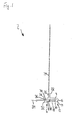
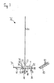
- Fig. 1 shows a not yet fixed first grout 2 in cross section.
- first plaster strip 2 has a horizontally extending base portion 4, in the left region, a web 22 projects forward away.
- a web 22 projects forward away.
- an upwardly extending reinforcing fabric 24 is secured by means of a weld 26.
- this is a welded joint, which has been created by ultrasonic welding by means of a separately supplied welding string, or a permanent bond.
- a first fixing area 6 and a second fixing area 12 are provided, which comprise a trough-shaped or semicircular adhesive strip receiving area 10 and 16 which faces rearward over a material bridge, in each of which a hotmelt adhesive strip 8 and 14 is received.
- an expansion strip 18 is arranged, which adheres with its upper side to the rear side of the base region 4 or is welded thereto, and whose rear side lies approximately at the level of the rear side of the hot-melt adhesive strips 8 and 14.
- a masking tape 20 extends from left to right over the hotmelt adhesive strip 8, over the expansion strip 18 and over the hotmelt adhesive strip 14.
- This masking tape 20 adheres with its left region to the underside of the hotmelt adhesive strip 8 and to its right region the underside of the hot-melt adhesive strip 14, and presses with its intermediate region intermediate the expansion strip 18 upwards and holds it in its compressed state.
- the expansion strip 18 is about 10 mm wide and in its compressed state has a thickness of about 2.5 mm.
- the expansion strip 18 has a delayed expansion, that is, after the removal of the cover strip 20, this expands to a maximum Ausdehnposition, which is at a level well below the undersides of the hot-melt adhesive strips 8 and 14.
- a Einputzschenkel 28 connects, which is plastered with and the outer left edge forms the edge for the top of the plaster layer.
- the top of Einputzschenkels 28, the left side of the web 22 and the transition region between them is provided with a channel profiling 30 to improve the adhesion of the plaster layer or the plaster layers on the first grout 2 by means of the thus enlarged surface.
- a soft cover lip 32 extends rearwardly approximately to the level of the back of the hotmelt adhesive strips 8 and 14 and the back of the expansion strip 18 or even further down.
- the cover lip 32 is slightly curved to the left rear and protects in the installed state of the plaster strip 2 against moisture and water.
- a strip-shaped protective tab 34 At the side end of Anputzschenkels 28 connects via a break-off material bridge lesser thickness 36, a strip-shaped protective tab 34, the front side is flat and the rear has a substantially perpendicular rearwardly projecting spacer web.
- the strip-shaped protective flap 34 has on its front side an adhesive layer to which a protective film, not shown here, can be glued.
- the cross section of the plaster strip 2 and the plaster strips described below is consistent over the entire length, so that the plaster strips can be easily prepared by extrusion.
- the covering lip 32 made of a softer material relative to the base material of the first plastering strip 2 and the adhesive strips can be coextruded.
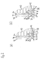
- Fig. 2 (a) shows the introduced in a transition between a thermal insulation 40 and a window frame 38 first grout 2 in horizontal section in a first state with a small gap extent
- Fig. 2 (b) shows them in horizontal section in a second state with large gap expansion.
- the window frame 38 can be provided, in particular, with a nanoparticle-coated surface, not shown separately, so that only adhesion but not permanent adhesion can be achieved.
- the first plaster strip 2 has been mounted on the window frame 38 after removal of the cover strip 20, in such a way that the hot-melt adhesive strips 8 and 14 adhere to the front of the window frame 38 or at least temporarily secure the plaster strip 2 thereto.
- the expansion strip 18 rests with its underside on the front side of the window frame 38.
- the heat insulation 38 has been fastened, in such a way that the right side of the web 22 of the first grout 2 and the adjacent thereto to the right front of the base portion 4 abut the corner region of the insulation 40.
- the gap 42 is reliably sealed by the base region 4 with the two hot-melt adhesive strips 8 and 14 and with the expansion strip 18 to the outside. This seal is still supported by the also applied to the window frame 38 cover lip 32.
- the gap has a width of 3 mm in the present exemplary embodiment.
- the area of the first plaster molding 2 between the right side of the web 22, which rests against the insulation 40 and the plastering edge of Anputzschenkels 28 together with the reinforcing fabric 24 and the channel profile 30 is plastered by means of a first layer of plaster 44 and a second layer of plaster 46 and thus reliable the thermal insulation 40 attached.
- the strip-shaped protective flap 34 has been separated after completion of the plastering work along the break-off material bridge 36, so that the strip-shaped protective flap 34 in Fig. 2 (a) no longer exists.
- the gap 42 has increased due to temperature-induced shrinkage of the thermal insulation 40, ie, the distance between thermal insulation 40 and window frame 38 has increased, so that the hot-melt adhesive strips 8 and 14 and the cover lip 32 no longer abut or adhere to the window frame 38 but rather that the hotmelt adhesive strips 8 and 14 and the covering lip 32 are at a distance from the window frame 38.
- the expansion strip 18, however, has expanded so that it compensates for the increase in the gap and that its underside still sealingly abuts the window frame 38 and provides a reliable seal of the space between the thermal insulation 40 and window frame 38.
- the Gap increased from 3 to 5 mm, and the expansion strip 18 has a thickness of about 4 mm, but still seals reliably against driving rain. It is possible to form the expansion strip 18 such that it experiences an expansion of more than 100% from a compressed state up to a maximum expansion state, for example from 2.5 mm to more than 5.0 mm, and at the same time is impact-proof. It is even possible to form the expansion strip 18 such that it experiences an expansion of more than 200% from a compressed state to a maximum expansion state, for example from 2.5 mm to more than 7.5 mm, and at the same time is impact-resistant ,
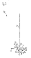
- Fig. 3 shows a not yet attached second grout bar 48 in cross section.
- the second plaster strip 48 corresponds with respect to most of its elements of the first plaster strip 2, and like elements are also identified by the same reference numerals.
- the second plaster strip 48 differs from the first plaster strip 2 in the formation of its fixing areas 50 and 56. These are formed as from the outer ends of the base portion 4 humped rear foot portions 52 and 58, on the flat underside adhesive tape strips 54 and 60 are attached , In an embodiment shown here, these can be double-sided adhesive tape strips, which are glued with their upper side to the flat undersides of the hump-shaped foot sections 52 and 58.
- the adhesive tape strip 20 is in both plaster strips 2 and 48 each a piece to the left on the left fixing region 6, 50 and a piece far to the right on the right fixing portion 12, 56 via.
- the thus projecting ends can be easily gripped to attach the cover strip 20 before installing the plaster strip 2, 48 in the gap 42 between the thermal insulation 40 and window frame 38.
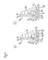
- Fig. 4 (a) shows the arranged in the transition between the thermal insulation 40 and the window frame 38 second plaster strip 48 in horizontal section in a first state with a small gap expansion and Fig. 4 (b) shows them in horizontal section in a second state with large gap expansion
- Fig. 4 (a) the hump-shaped foot sections 52, 58 are fixed to the window frame 38 by means of their adhesive tape strips 54 and 60.
- the gap between the thermal insulation 40 and the window frame 38 is reliably sealed off to the outside by the expansion strip 18, by the adhesive tape strips 54 and 60 and by the cover lip 32.
- the adhesive tape strips 54 and 60 and the cover lip 32 are arranged at a distance from the window frame 38.
- the expanded expansion strip 18 continues with its underside still on the window frame 38 and seals the gap between the thermal insulation 40 and window frame 38 reliably and permanently.
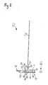
- Fig. 5 shows a not yet attached third plaster molding 62 in cross-section and a perspective view of a suction cup 66 used therein.
- the third plaster molding 62 corresponds to most of its elements of the first plaster molding 2, and like elements are also identified by the same reference numerals.
- the fixing regions 64 and 70 are designed as rows of suction cups 72 which are used in the third plastering strip 62 and which are respectively inserted into groove-shaped or semicircular suction cup receiving regions 68 and 72, in particular clipped into them.
- the masking tape 75 which covers the suction cups 66 and 72 and also holds the expansion strip 18 in its compressed state, extends to the left over the cover lip 32, the spacer web of the protective flap 34 over the end of the protective flap 34 to the front of the protective flap 34 and attached there by means of a bond, not shown.
- the cover tape 75 extends upwardly and is fixed to the right wall of the right suction cup receiving portion 74 by bonding.
- Fig. 6 (a) shows the arranged in the transition between the thermal insulation 40 and the window frame 38 third plaster strip 62 in horizontal section in a first state with a small gap expansion and Fig. 6 (b) shows them in horizontal section in a second state with large gap expansion.
- Fig. 7 shows a not yet attached fourth grout bar 76 in cross-section and a perspective view of a used therein suction belt 80 with integrated therein used suction cups 82nd
- the fourth plaster bar 76 corresponds to the third plaster bar 62 with respect to most of its elements, and like elements are also identified by the same reference numerals.
- the suction cups 82 and 90 are integrated into suction belts 80 and 88, and a first suction belt 80 is inserted into the semicircular suction channel receiving portion 84 of the first fixing portion 78 and also, a second suction belt 88 having suction cups 90 integrated therein is inserted into a semicircular suction channel receiving portion 92 of the second fixing portion 86.
- Fig. 8 (a) shows arranged in the transition between the insulation 40 and the window frame 38 fourth grout 76 in horizontal section in a first state with a small gap expansion; and Fig. 8 (b) shows them in horizontal section in a second state with large gap expansion.
- the fourth grout bar 76 is attached to the window frame 38 by means of the integrated suction cups 82.
- the sealing effect is achieved by the expansion strip 18, by the suction belts 80 and 88, which also bear tightly against the window frame 38, and reached by the cover lip 32.
- Fig. 9 shows a not yet fixed fifth grout 94 in cross section.
- the fifth plaster bar 94 corresponds to most of its elements of the second plaster bar 48, and like elements are also identified by the same reference numerals.
- the fifth plaster strip 94 differs from the second plaster strip 48 in the formation of its fixing regions 96 and 102.
- the fixing regions 96 and 102 have a staple-shaped formation or essentially the shape of an L or an inverted L, and they extend from the left or right end of the base portion 4 to the rear.
- Double-sided adhesive tape strips 100 and 106 are applied to the rear sides of the straight foot sections 98 and 104.
- a cover strip 20 is provided which adheres to the adhesive tape strips 100 and 106 and which holds the expansion strip 18 arranged therebetween in its compressed state.
- Fig. 10 (a) shows the arranged in the transition between the thermal insulation 40 and the window frame 38 fifth grout 94 in horizontal section in a first state with a small gap expansion; and Fig. 8 (b) shows them in horizontal section in a second state with large gap expansion.
- the presentation largely corresponds to the representation in Fig. 4
- the staple-shaped foot portions 98 and 104 are fixed by means of their adhesive tape strips 100 and 106 on the window frame 38.
Landscapes
- Engineering & Computer Science (AREA)
- Architecture (AREA)
- Civil Engineering (AREA)
- Structural Engineering (AREA)
- Mechanical Engineering (AREA)
- Building Environments (AREA)
- Adhesives Or Adhesive Processes (AREA)
Priority Applications (2)
| Application Number | Priority Date | Filing Date | Title |
|---|---|---|---|
| PL10162273T PL2292886T3 (pl) | 2009-07-23 | 2010-05-07 | Jednoczęściowa listwa uszczelniająca lub podtynkowa |
| SI201030959T SI2292886T1 (sl) | 2009-07-23 | 2010-05-07 | Enodelna tesnilna ali ometna letev |
Applications Claiming Priority (1)
| Application Number | Priority Date | Filing Date | Title |
|---|---|---|---|
| DE102009034445A DE102009034445A1 (de) | 2009-07-23 | 2009-07-23 | Einteilige Abdicht- oder Anputzleiste |
Publications (3)
| Publication Number | Publication Date |
|---|---|
| EP2292886A2 true EP2292886A2 (fr) | 2011-03-09 |
| EP2292886A3 EP2292886A3 (fr) | 2011-12-14 |
| EP2292886B1 EP2292886B1 (fr) | 2015-03-25 |
Family
ID=42953774
Family Applications (1)
| Application Number | Title | Priority Date | Filing Date |
|---|---|---|---|
| EP10162273.6A Active EP2292886B1 (fr) | 2009-07-23 | 2010-05-07 | Bande d'étanchéité ou de crépissage en une partie |
Country Status (5)
| Country | Link |
|---|---|
| EP (1) | EP2292886B1 (fr) |
| DE (1) | DE102009034445A1 (fr) |
| HU (1) | HUE024973T2 (fr) |
| PL (1) | PL2292886T3 (fr) |
| SI (1) | SI2292886T1 (fr) |
Cited By (2)
| Publication number | Priority date | Publication date | Assignee | Title |
|---|---|---|---|---|
| DE102012223268A1 (de) * | 2012-12-14 | 2014-06-18 | Protektorwerk Florenz Maisch Gmbh & Co. Kg | Laibungsanschlussprofil |
| DE202017007004U1 (de) | 2016-08-08 | 2019-02-25 | Christian Mick | Anschlussprofilleiste |
Families Citing this family (4)
| Publication number | Priority date | Publication date | Assignee | Title |
|---|---|---|---|---|
| AT13185U1 (de) * | 2012-07-02 | 2013-08-15 | AF Tec Beteiligungs GmbH | Laibungsanschlußprofil für an Putz angrenzende Bauteile |
| AT521892B1 (de) | 2018-11-19 | 2021-03-15 | AF Tec Beteiligungs GmbH | Anschlussprofil |
| ES2900948A1 (es) * | 2020-09-18 | 2022-03-18 | Univ Sevilla | Premarco de autosellado |
| AT526956B1 (de) | 2023-10-06 | 2024-09-15 | Christian Mick Mag | Anputzdichtleiste |
Citations (1)
| Publication number | Priority date | Publication date | Assignee | Title |
|---|---|---|---|---|
| WO1993017204A1 (fr) | 1992-02-26 | 1993-09-02 | August Braun | Bande de crepissage et de protection pour châssis de fenetre, bâtis de porte ou analogue pour la jonction avec le crepi |
Family Cites Families (5)
| Publication number | Priority date | Publication date | Assignee | Title |
|---|---|---|---|---|
| DE29922461U1 (de) * | 1999-12-22 | 2000-03-02 | Menke Kunststoffe GmbH & Co. KG, 59581 Warstein | Einrichtung zur Abdichtung eines Fensterrahmens |
| DE20107556U1 (de) * | 2001-04-30 | 2001-08-02 | Lorentz, Doris, 66333 Völklingen | Befestigung für Putzleisten |
| DE102005057778A1 (de) * | 2005-12-02 | 2007-06-06 | August Braun | Putzabschlussleiste für eine Putzschicht auf einer Wärmedämmung |
| DE102007048311B4 (de) * | 2007-10-09 | 2022-08-11 | August Braun | Anputzleiste für den Übergang zwischen einem Fensterrahmen oder Türrahmen und einer Wärmedämmung |
| AT10453U1 (de) * | 2008-02-22 | 2009-03-15 | Peter Kassmannhuber | Laibungsanschlussprofil für an putz angrenzende bauteile |
-
2009
- 2009-07-23 DE DE102009034445A patent/DE102009034445A1/de not_active Withdrawn
-
2010
- 2010-05-07 EP EP10162273.6A patent/EP2292886B1/fr active Active
- 2010-05-07 SI SI201030959T patent/SI2292886T1/sl unknown
- 2010-05-07 HU HUE10162273A patent/HUE024973T2/en unknown
- 2010-05-07 PL PL10162273T patent/PL2292886T3/pl unknown
Patent Citations (1)
| Publication number | Priority date | Publication date | Assignee | Title |
|---|---|---|---|---|
| WO1993017204A1 (fr) | 1992-02-26 | 1993-09-02 | August Braun | Bande de crepissage et de protection pour châssis de fenetre, bâtis de porte ou analogue pour la jonction avec le crepi |
Cited By (2)
| Publication number | Priority date | Publication date | Assignee | Title |
|---|---|---|---|---|
| DE102012223268A1 (de) * | 2012-12-14 | 2014-06-18 | Protektorwerk Florenz Maisch Gmbh & Co. Kg | Laibungsanschlussprofil |
| DE202017007004U1 (de) | 2016-08-08 | 2019-02-25 | Christian Mick | Anschlussprofilleiste |
Also Published As
| Publication number | Publication date |
|---|---|
| SI2292886T1 (sl) | 2015-10-30 |
| EP2292886B1 (fr) | 2015-03-25 |
| PL2292886T3 (pl) | 2015-11-30 |
| DE102009034445A1 (de) | 2011-01-27 |
| HUE024973T2 (en) | 2016-01-28 |
| EP2292886A3 (fr) | 2011-12-14 |
Similar Documents
| Publication | Publication Date | Title |
|---|---|---|
| EP1967107B1 (fr) | Joint pour des dispositifs sanitaires | |
| EP2292886B1 (fr) | Bande d'étanchéité ou de crépissage en une partie | |
| EP2404008B1 (fr) | Dispositif d'étanchéité sur un joint dans une construction | |
| EP0398937A1 (fr) | Bande de protection pour jonctions de crepi lors du crepissage. | |
| EP2492428B1 (fr) | Bande de crépissage ainsi qu'angles de construction dotés d'une bande de crépissage | |
| EP2492429B3 (fr) | Bande de crépissage ainsi qu'angles de construction dotés d'une bande de crépissage | |
| DE202009010042U1 (de) | Einteilige Abdicht- oder Anputzleiste | |
| EP2273037B1 (fr) | Profilé de raccordement, en particulier profilé de raccordement d'intrados | |
| EP3805480B1 (fr) | Bande d'étanchéité en plâtre | |
| EP3372133B1 (fr) | Ensemble de bande de montage et d'étanchéité | |
| DE202013011085U1 (de) | Anputzleiste, Leiste und Abschlussschiene | |
| EP1722064B1 (fr) | Profilé de jonction, notamment profilé de jonction de tableau | |
| AT630U1 (de) | Anputz- und schutzleiste für fensterstöcke, türstöcke oder dergleichen am übergang zu putz | |
| DE202014102622U1 (de) | Putzleiste | |
| EP1655440B1 (fr) | Listel profilé permettant d'établir une transition entre un élément de construction et une surface de bâtiment | |
| DE102013110110A1 (de) | Anputzleiste, Abschlussschiene und Putz-Eckleiste und Verfahren zum Herstellen derselben | |
| EP4249719A1 (fr) | Profilé de raccordement | |
| AT8398U1 (de) | Zweiteiliges laibungsanschlussprofil | |
| DE202009013120U1 (de) | Einteilige Anputzleiste sowie Übergang zwischen zwei Bestandteilen eines Gebäudes | |
| AT506968B1 (de) | Anschlussprofil für an dämmstofflagen mit putz angrenzende bauteile | |
| WO2009000437A1 (fr) | Baguette de raccordement d'enduit pour la douelle de fenêtres et de portes | |
| EP4541996A1 (fr) | Baguette de crépissage | |
| EP3653805B1 (fr) | Profil de raccordement | |
| EP4428320A1 (fr) | Baguette d'étanchéité en plâtre | |
| EP4339393A1 (fr) | Baguette de crépissage ainsi que transition de bâtiment |
Legal Events
| Date | Code | Title | Description |
|---|---|---|---|
| PUAI | Public reference made under article 153(3) epc to a published international application that has entered the european phase |
Free format text: ORIGINAL CODE: 0009012 |
|
| AK | Designated contracting states |
Kind code of ref document: A2 Designated state(s): AL AT BE BG CH CY CZ DE DK EE ES FI FR GB GR HR HU IE IS IT LI LT LU LV MC MK MT NL NO PL PT RO SE SI SK SM TR |
|
| AX | Request for extension of the european patent |
Extension state: BA ME RS |
|
| PUAL | Search report despatched |
Free format text: ORIGINAL CODE: 0009013 |
|
| AK | Designated contracting states |
Kind code of ref document: A3 Designated state(s): AL AT BE BG CH CY CZ DE DK EE ES FI FR GB GR HR HU IE IS IT LI LT LU LV MC MK MT NL NO PL PT RO SE SI SK SM TR |
|
| AX | Request for extension of the european patent |
Extension state: BA ME RS |
|
| RIC1 | Information provided on ipc code assigned before grant |
Ipc: E06B 1/62 20060101AFI20111110BHEP Ipc: E04G 21/30 20060101ALI20111110BHEP Ipc: E04F 13/06 20060101ALI20111110BHEP |
|
| 17P | Request for examination filed |
Effective date: 20120613 |
|
| GRAP | Despatch of communication of intention to grant a patent |
Free format text: ORIGINAL CODE: EPIDOSNIGR1 |
|
| INTG | Intention to grant announced |
Effective date: 20140724 |
|
| GRAS | Grant fee paid |
Free format text: ORIGINAL CODE: EPIDOSNIGR3 |
|
| GRAP | Despatch of communication of intention to grant a patent |
Free format text: ORIGINAL CODE: EPIDOSNIGR1 |
|
| GRAA | (expected) grant |
Free format text: ORIGINAL CODE: 0009210 |
|
| INTG | Intention to grant announced |
Effective date: 20150211 |
|
| AK | Designated contracting states |
Kind code of ref document: B1 Designated state(s): AL AT BE BG CH CY CZ DE DK EE ES FI FR GB GR HR HU IE IS IT LI LT LU LV MC MK MT NL NO PL PT RO SE SI SK SM TR |
|
| REG | Reference to a national code |
Ref country code: GB Ref legal event code: FG4D Free format text: NOT ENGLISH |
|
| REG | Reference to a national code |
Ref country code: CH Ref legal event code: EP |
|
| REG | Reference to a national code |
Ref country code: IE Ref legal event code: FG4D Free format text: LANGUAGE OF EP DOCUMENT: GERMAN |
|
| REG | Reference to a national code |
Ref country code: DE Ref legal event code: R096 Ref document number: 502010009188 Country of ref document: DE Effective date: 20150507 |
|
| REG | Reference to a national code |
Ref country code: AT Ref legal event code: REF Ref document number: 718001 Country of ref document: AT Kind code of ref document: T Effective date: 20150515 |
|
| REG | Reference to a national code |
Ref country code: RO Ref legal event code: EPE |
|
| REG | Reference to a national code |
Ref country code: NL Ref legal event code: T3 |
|
| PG25 | Lapsed in a contracting state [announced via postgrant information from national office to epo] |
Ref country code: LT Free format text: LAPSE BECAUSE OF FAILURE TO SUBMIT A TRANSLATION OF THE DESCRIPTION OR TO PAY THE FEE WITHIN THE PRESCRIBED TIME-LIMIT Effective date: 20150325 Ref country code: NO Free format text: LAPSE BECAUSE OF FAILURE TO SUBMIT A TRANSLATION OF THE DESCRIPTION OR TO PAY THE FEE WITHIN THE PRESCRIBED TIME-LIMIT Effective date: 20150625 Ref country code: HR Free format text: LAPSE BECAUSE OF FAILURE TO SUBMIT A TRANSLATION OF THE DESCRIPTION OR TO PAY THE FEE WITHIN THE PRESCRIBED TIME-LIMIT Effective date: 20150325 Ref country code: FI Free format text: LAPSE BECAUSE OF FAILURE TO SUBMIT A TRANSLATION OF THE DESCRIPTION OR TO PAY THE FEE WITHIN THE PRESCRIBED TIME-LIMIT Effective date: 20150325 Ref country code: SE Free format text: LAPSE BECAUSE OF FAILURE TO SUBMIT A TRANSLATION OF THE DESCRIPTION OR TO PAY THE FEE WITHIN THE PRESCRIBED TIME-LIMIT Effective date: 20150325 |
|
| REG | Reference to a national code |
Ref country code: CH Ref legal event code: NV Representative=s name: THOMANNFISCHER ADVOKATUR UND NOTARIAT, CH |
|
| REG | Reference to a national code |
Ref country code: LT Ref legal event code: MG4D |
|
| PG25 | Lapsed in a contracting state [announced via postgrant information from national office to epo] |
Ref country code: LV Free format text: LAPSE BECAUSE OF FAILURE TO SUBMIT A TRANSLATION OF THE DESCRIPTION OR TO PAY THE FEE WITHIN THE PRESCRIBED TIME-LIMIT Effective date: 20150325 Ref country code: GR Free format text: LAPSE BECAUSE OF FAILURE TO SUBMIT A TRANSLATION OF THE DESCRIPTION OR TO PAY THE FEE WITHIN THE PRESCRIBED TIME-LIMIT Effective date: 20150626 |
|
| PG25 | Lapsed in a contracting state [announced via postgrant information from national office to epo] |
Ref country code: EE Free format text: LAPSE BECAUSE OF FAILURE TO SUBMIT A TRANSLATION OF THE DESCRIPTION OR TO PAY THE FEE WITHIN THE PRESCRIBED TIME-LIMIT Effective date: 20150325 Ref country code: PT Free format text: LAPSE BECAUSE OF FAILURE TO SUBMIT A TRANSLATION OF THE DESCRIPTION OR TO PAY THE FEE WITHIN THE PRESCRIBED TIME-LIMIT Effective date: 20150727 Ref country code: ES Free format text: LAPSE BECAUSE OF FAILURE TO SUBMIT A TRANSLATION OF THE DESCRIPTION OR TO PAY THE FEE WITHIN THE PRESCRIBED TIME-LIMIT Effective date: 20150325 |
|
| REG | Reference to a national code |
Ref country code: SK Ref legal event code: T3 Ref document number: E 19000 Country of ref document: SK |
|
| PG25 | Lapsed in a contracting state [announced via postgrant information from national office to epo] |
Ref country code: IS Free format text: LAPSE BECAUSE OF FAILURE TO SUBMIT A TRANSLATION OF THE DESCRIPTION OR TO PAY THE FEE WITHIN THE PRESCRIBED TIME-LIMIT Effective date: 20150725 |
|
| REG | Reference to a national code |
Ref country code: PL Ref legal event code: T3 |
|
| REG | Reference to a national code |
Ref country code: DE Ref legal event code: R097 Ref document number: 502010009188 Country of ref document: DE |
|
| REG | Reference to a national code |
Ref country code: HU Ref legal event code: AG4A Ref document number: E024973 Country of ref document: HU |
|
| PG25 | Lapsed in a contracting state [announced via postgrant information from national office to epo] |
Ref country code: MC Free format text: LAPSE BECAUSE OF FAILURE TO SUBMIT A TRANSLATION OF THE DESCRIPTION OR TO PAY THE FEE WITHIN THE PRESCRIBED TIME-LIMIT Effective date: 20150325 Ref country code: DK Free format text: LAPSE BECAUSE OF FAILURE TO SUBMIT A TRANSLATION OF THE DESCRIPTION OR TO PAY THE FEE WITHIN THE PRESCRIBED TIME-LIMIT Effective date: 20150325 Ref country code: LU Free format text: LAPSE BECAUSE OF FAILURE TO SUBMIT A TRANSLATION OF THE DESCRIPTION OR TO PAY THE FEE WITHIN THE PRESCRIBED TIME-LIMIT Effective date: 20150507 |
|
| PLBE | No opposition filed within time limit |
Free format text: ORIGINAL CODE: 0009261 |
|
| STAA | Information on the status of an ep patent application or granted ep patent |
Free format text: STATUS: NO OPPOSITION FILED WITHIN TIME LIMIT |
|
| REG | Reference to a national code |
Ref country code: IE Ref legal event code: MM4A |
|
| 26N | No opposition filed |
Effective date: 20160105 |
|
| PG25 | Lapsed in a contracting state [announced via postgrant information from national office to epo] |
Ref country code: IE Free format text: LAPSE BECAUSE OF NON-PAYMENT OF DUE FEES Effective date: 20150507 |
|
| REG | Reference to a national code |
Ref country code: FR Ref legal event code: PLFP Year of fee payment: 7 |
|
| REG | Reference to a national code |
Ref country code: DE Ref legal event code: R082 Ref document number: 502010009188 Country of ref document: DE Representative=s name: SCHMITT-NILSON SCHRAUD WAIBEL WOHLFROM PATENTA, DE Ref country code: DE Ref legal event code: R082 Ref document number: 502010009188 Country of ref document: DE Representative=s name: KSNH PATENTANWAELTE KLUNKER/SCHMITT-NILSON/HIR, DE Ref country code: DE Ref legal event code: R081 Ref document number: 502010009188 Country of ref document: DE Owner name: BRAUN, AUGUST, CZ Free format text: FORMER OWNER: BRAUN, AUGUST, SCHAFFHAUSEN, CH |
|
| REG | Reference to a national code |
Ref country code: SI Ref legal event code: SP73 Owner name: AUGUST BRAUN; CZ Effective date: 20161004 |
|
| PG25 | Lapsed in a contracting state [announced via postgrant information from national office to epo] |
Ref country code: MT Free format text: LAPSE BECAUSE OF FAILURE TO SUBMIT A TRANSLATION OF THE DESCRIPTION OR TO PAY THE FEE WITHIN THE PRESCRIBED TIME-LIMIT Effective date: 20150325 |
|
| REG | Reference to a national code |
Ref country code: FR Ref legal event code: PLFP Year of fee payment: 8 |
|
| PG25 | Lapsed in a contracting state [announced via postgrant information from national office to epo] |
Ref country code: BG Free format text: LAPSE BECAUSE OF FAILURE TO SUBMIT A TRANSLATION OF THE DESCRIPTION OR TO PAY THE FEE WITHIN THE PRESCRIBED TIME-LIMIT Effective date: 20150325 Ref country code: SM Free format text: LAPSE BECAUSE OF FAILURE TO SUBMIT A TRANSLATION OF THE DESCRIPTION OR TO PAY THE FEE WITHIN THE PRESCRIBED TIME-LIMIT Effective date: 20150325 |
|
| PG25 | Lapsed in a contracting state [announced via postgrant information from national office to epo] |
Ref country code: CY Free format text: LAPSE BECAUSE OF FAILURE TO SUBMIT A TRANSLATION OF THE DESCRIPTION OR TO PAY THE FEE WITHIN THE PRESCRIBED TIME-LIMIT Effective date: 20150325 |
|
| REG | Reference to a national code |
Ref country code: DE Ref legal event code: R082 Ref document number: 502010009188 Country of ref document: DE Representative=s name: SCHMITT-NILSON SCHRAUD WAIBEL WOHLFROM PATENTA, DE |
|
| PG25 | Lapsed in a contracting state [announced via postgrant information from national office to epo] |
Ref country code: TR Free format text: LAPSE BECAUSE OF FAILURE TO SUBMIT A TRANSLATION OF THE DESCRIPTION OR TO PAY THE FEE WITHIN THE PRESCRIBED TIME-LIMIT Effective date: 20150325 |
|
| REG | Reference to a national code |
Ref country code: CH Ref legal event code: PCOW Free format text: NEW ADDRESS: CESKE VRBNE 23940, 30711 CESKE BUDEJOVICE (CZ) Ref country code: CH Ref legal event code: PCOW Free format text: NEW ADDRESS: CESKE VRBNE 2390, 37011 CESKE BUDEJOVICE (CZ) |
|
| REG | Reference to a national code |
Ref country code: SK Ref legal event code: TE4A Ref document number: E 19000 Country of ref document: SK Owner name: BRAUN AUGUST, CESKE BUDEJOVICE, CZ Effective date: 20180220 |
|
| REG | Reference to a national code |
Ref country code: HU Ref legal event code: HC9C |
|
| REG | Reference to a national code |
Ref country code: FR Ref legal event code: PLFP Year of fee payment: 9 |
|
| PG25 | Lapsed in a contracting state [announced via postgrant information from national office to epo] |
Ref country code: MK Free format text: LAPSE BECAUSE OF FAILURE TO SUBMIT A TRANSLATION OF THE DESCRIPTION OR TO PAY THE FEE WITHIN THE PRESCRIBED TIME-LIMIT Effective date: 20150325 |
|
| REG | Reference to a national code |
Ref country code: FR Ref legal event code: CA Effective date: 20180620 |
|
| PG25 | Lapsed in a contracting state [announced via postgrant information from national office to epo] |
Ref country code: AL Free format text: LAPSE BECAUSE OF FAILURE TO SUBMIT A TRANSLATION OF THE DESCRIPTION OR TO PAY THE FEE WITHIN THE PRESCRIBED TIME-LIMIT Effective date: 20150325 |
|
| REG | Reference to a national code |
Ref country code: FR Ref legal event code: PLFP Year of fee payment: 13 |
|
| REG | Reference to a national code |
Ref country code: DE Ref legal event code: R081 Ref document number: 502010009188 Country of ref document: DE Owner name: BRAUN, MAGDALENA, CH Free format text: FORMER OWNER: BRAUN, AUGUST, CESKE BUDEJOVICE, CZ |
|
| REG | Reference to a national code |
Ref country code: HU Ref legal event code: GB9C Owner name: MAGDALENA BRAUN, CH Free format text: FORMER OWNER(S): BRAUN, AUGUST, CH; BRAUN, AUGUST, CZ Ref country code: HU Ref legal event code: FH1C Free format text: FORMER REPRESENTATIVE(S): SIPOS JOZSEF, DANUBIA SZABADALMI ES JOGI IRODA KFT., HU Representative=s name: DANUBIA SZABADALMI ES JOGI IRODA KFT., HU |
|
| REG | Reference to a national code |
Ref country code: BE Ref legal event code: PD Owner name: BRAUN MAGDALENA; CH Free format text: DETAILS ASSIGNMENT: CHANGE OF OWNER(S), SUCCESSION; FORMER OWNER NAME: BRAUN, AUGUST Effective date: 20230306 |
|
| REG | Reference to a national code |
Ref country code: GB Ref legal event code: 732E Free format text: REGISTERED BETWEEN 20230413 AND 20230419 |
|
| REG | Reference to a national code |
Ref country code: NL Ref legal event code: PD Owner name: MAGDALENA BRAUN; CH Free format text: DETAILS ASSIGNMENT: CHANGE OF OWNER(S), SUCCESSION; FORMER OWNER NAME: BRAUN, AUGUST Effective date: 20230504 |
|
| REG | Reference to a national code |
Ref country code: SK Ref legal event code: PC4A Ref document number: E 19000 Country of ref document: SK Owner name: BRAUN MAGDALENA, EGG, CH Free format text: FORMER OWNER: BRAUN AUGUST, CESKE BUDEJOVICE, CZ Effective date: 20230523 |
|
| REG | Reference to a national code |
Ref country code: AT Ref legal event code: PC Ref document number: 718001 Country of ref document: AT Kind code of ref document: T Owner name: MAGDALENA BRAUN, CH Effective date: 20230508 |
|
| P01 | Opt-out of the competence of the unified patent court (upc) registered |
Effective date: 20230527 |
|
| REG | Reference to a national code |
Ref country code: SI Ref legal event code: SP73 Owner name: MAGDALENA BRAUN; CH Effective date: 20230810 |
|
| PGFP | Annual fee paid to national office [announced via postgrant information from national office to epo] |
Ref country code: NL Payment date: 20250522 Year of fee payment: 16 |
|
| PGFP | Annual fee paid to national office [announced via postgrant information from national office to epo] |
Ref country code: PL Payment date: 20250425 Year of fee payment: 16 |
|
| PGFP | Annual fee paid to national office [announced via postgrant information from national office to epo] |
Ref country code: BE Payment date: 20250520 Year of fee payment: 16 Ref country code: IT Payment date: 20250530 Year of fee payment: 16 |
|
| PGFP | Annual fee paid to national office [announced via postgrant information from national office to epo] |
Ref country code: HU Payment date: 20250505 Year of fee payment: 16 Ref country code: FR Payment date: 20250523 Year of fee payment: 16 |
|
| PGFP | Annual fee paid to national office [announced via postgrant information from national office to epo] |
Ref country code: CH Payment date: 20250601 Year of fee payment: 16 |
|
| PGFP | Annual fee paid to national office [announced via postgrant information from national office to epo] |
Ref country code: RO Payment date: 20250430 Year of fee payment: 16 Ref country code: AT Payment date: 20250519 Year of fee payment: 16 |
|
| PGFP | Annual fee paid to national office [announced via postgrant information from national office to epo] |
Ref country code: SK Payment date: 20250424 Year of fee payment: 16 |
|
| PGFP | Annual fee paid to national office [announced via postgrant information from national office to epo] |
Ref country code: CZ Payment date: 20250424 Year of fee payment: 16 |
|
| PGFP | Annual fee paid to national office [announced via postgrant information from national office to epo] |
Ref country code: SI Payment date: 20250428 Year of fee payment: 16 |
|
| PGFP | Annual fee paid to national office [announced via postgrant information from national office to epo] |
Ref country code: DE Payment date: 20250723 Year of fee payment: 16 |
|
| REG | Reference to a national code |
Ref country code: CH Ref legal event code: R18 Free format text: ST27 STATUS EVENT CODE: U-0-0-R10-R18 (AS PROVIDED BY THE NATIONAL OFFICE) Effective date: 20260211 |
|
| PGFP | Annual fee paid to national office [announced via postgrant information from national office to epo] |
Ref country code: GB Payment date: 20260324 Year of fee payment: 17 |