EP2292962B1 - Raccord à sertir pour un tuyau - Google Patents
Raccord à sertir pour un tuyau Download PDFInfo
- Publication number
- EP2292962B1 EP2292962B1 EP10196193A EP10196193A EP2292962B1 EP 2292962 B1 EP2292962 B1 EP 2292962B1 EP 10196193 A EP10196193 A EP 10196193A EP 10196193 A EP10196193 A EP 10196193A EP 2292962 B1 EP2292962 B1 EP 2292962B1
- Authority
- EP
- European Patent Office
- Prior art keywords
- pressing
- sleeve
- press fitting
- pressing sleeve
- fitting according
- Prior art date
- Legal status (The legal status is an assumption and is not a legal conclusion. Google has not performed a legal analysis and makes no representation as to the accuracy of the status listed.)
- Active
Links
Images
Classifications
-
- F—MECHANICAL ENGINEERING; LIGHTING; HEATING; WEAPONS; BLASTING
- F16—ENGINEERING ELEMENTS AND UNITS; GENERAL MEASURES FOR PRODUCING AND MAINTAINING EFFECTIVE FUNCTIONING OF MACHINES OR INSTALLATIONS; THERMAL INSULATION IN GENERAL
- F16L—PIPES; JOINTS OR FITTINGS FOR PIPES; SUPPORTS FOR PIPES, CABLES OR PROTECTIVE TUBING; MEANS FOR THERMAL INSULATION IN GENERAL
- F16L13/00—Non-disconnectable pipe joints, e.g. soldered, adhesive, or caulked joints
- F16L13/14—Non-disconnectable pipe joints, e.g. soldered, adhesive, or caulked joints made by plastically deforming the material of the pipe, e.g. by flanging, rolling
- F16L13/141—Non-disconnectable pipe joints, e.g. soldered, adhesive, or caulked joints made by plastically deforming the material of the pipe, e.g. by flanging, rolling by crimping or rolling from the outside
-
- F—MECHANICAL ENGINEERING; LIGHTING; HEATING; WEAPONS; BLASTING
- F16—ENGINEERING ELEMENTS AND UNITS; GENERAL MEASURES FOR PRODUCING AND MAINTAINING EFFECTIVE FUNCTIONING OF MACHINES OR INSTALLATIONS; THERMAL INSULATION IN GENERAL
- F16L—PIPES; JOINTS OR FITTINGS FOR PIPES; SUPPORTS FOR PIPES, CABLES OR PROTECTIVE TUBING; MEANS FOR THERMAL INSULATION IN GENERAL
- F16L33/00—Arrangements for connecting hoses to rigid members; Rigid hose-connectors, i.e. single members engaging both hoses
- F16L33/20—Undivided rings, sleeves, or like members contracted on the hose or expanded inside the hose by means of tools; Arrangements using such members
- F16L33/207—Undivided rings, sleeves, or like members contracted on the hose or expanded inside the hose by means of tools; Arrangements using such members only a sleeve being contracted on the hose
- F16L33/2071—Undivided rings, sleeves, or like members contracted on the hose or expanded inside the hose by means of tools; Arrangements using such members only a sleeve being contracted on the hose the sleeve being a separate connecting member
- F16L33/2073—Undivided rings, sleeves, or like members contracted on the hose or expanded inside the hose by means of tools; Arrangements using such members only a sleeve being contracted on the hose the sleeve being a separate connecting member directly connected to the rigid member
- F16L33/2075—Undivided rings, sleeves, or like members contracted on the hose or expanded inside the hose by means of tools; Arrangements using such members only a sleeve being contracted on the hose the sleeve being a separate connecting member directly connected to the rigid member by quick acting
-
- F—MECHANICAL ENGINEERING; LIGHTING; HEATING; WEAPONS; BLASTING
- F16—ENGINEERING ELEMENTS AND UNITS; GENERAL MEASURES FOR PRODUCING AND MAINTAINING EFFECTIVE FUNCTIONING OF MACHINES OR INSTALLATIONS; THERMAL INSULATION IN GENERAL
- F16L—PIPES; JOINTS OR FITTINGS FOR PIPES; SUPPORTS FOR PIPES, CABLES OR PROTECTIVE TUBING; MEANS FOR THERMAL INSULATION IN GENERAL
- F16L2201/00—Special arrangements for pipe couplings
- F16L2201/10—Indicators for correct coupling
-
- Y—GENERAL TAGGING OF NEW TECHNOLOGICAL DEVELOPMENTS; GENERAL TAGGING OF CROSS-SECTIONAL TECHNOLOGIES SPANNING OVER SEVERAL SECTIONS OF THE IPC; TECHNICAL SUBJECTS COVERED BY FORMER USPC CROSS-REFERENCE ART COLLECTIONS [XRACs] AND DIGESTS
- Y10—TECHNICAL SUBJECTS COVERED BY FORMER USPC
- Y10T—TECHNICAL SUBJECTS COVERED BY FORMER US CLASSIFICATION
- Y10T29/00—Metal working
- Y10T29/49—Method of mechanical manufacture
- Y10T29/49826—Assembling or joining
- Y10T29/49908—Joining by deforming
- Y10T29/49909—Securing cup or tube between axially extending concentric annuli
- Y10T29/49913—Securing cup or tube between axially extending concentric annuli by constricting outer annulus
Definitions
- the invention relates to a press fitting for a pipe, which is in particular a plastic pipe or a plastic-metal composite pipe.
- Press fittings for pipes generally have a fitting body provided with a support sleeve onto which the end of a pipe to be connected is pushed.
- the compression sleeve and the tube end pushed onto it are surrounded by a plastically deformable compression sleeve, which is radially compressed by means of a pressing tool and thus pressed against the tube, so that it is both tight against the press fitting and fixed.
- the contact element serves as a stop for the pressing tool and for guiding the pressing tool during the deformation of the compression sleeve.
- EPC shows a press fitting for a pipe, in which T, L and U-shaped grout marking sections project into the area of action of the press sleeve. They are connected via predetermined breaking points with the contact element and are separated by the pressing tool in the deformation of the compression sleeve of the contact element. The separated Verpresskennyogyogyogyogyogyogyogyogyogyogyogyogyogyogyogyogyogyogyogyogyogyogyogyogyogyogyogyogyogyogyogyogtulabitese serve to identify a correctly performed compression.
- the pressing tool acts with its pressing surface on the Verpresskennyogsabexcellente of the contact element.
- these Verpresskennyogsabexcellente be bent radially inwardly.
- the case may occur that the compression sleeve moves axially relative to the pressing tool, so that the compression of the compression sleeve is not in the prescribed position, as defined by investment of the pressing tool on the contact element takes place.
- the object of the invention is to provide a press fitting for a pipe, in particular plastic pipe or plastic-metal composite pipe, which is easier and more reliable to handle in the pressing.
- the Verpresskennyogyogyogyogyogyogyogyogyogyogyogyogyogyogyogyogyogyogyogyogyogyogyogyogyogyogyogyogyogyogyogyogyogyogyogyogyogyogyogyogyogyogyogyogyogyogyogyogyogyogyogyogyogyogyogyogyogyogyogyogyogyogyogyogyogyogyogyogyogyogyogyogyogyogyogyogyogyogyogyogyogyogyogyogyogyogyogyogyogyogyogyogyogyogyogyogyogyogyogyogyogyogyogyogyogyogyogyogyogtulabites for axially fixing the compression sleeve relative to the pressing tool in the deformation of the compression sleeve has a guide recess for receiving a guide projection of the pressing tool and / or a guide projection for receiving in a guide recess of the pressing tool.
- the press fitting according to the invention is provided with formations which allow an interaction of the pressing tool with the at least one Verpresskennyogsabrough during the compression of the compression sleeve for the axial fixation of the pressing tool and compression sleeve.
- the at least one Verpresskennyogsabrough a guide recess into which a guide projection of the pressing tool, which is formed in particular on the pressing surface of the pressing tool, for axial fixation of the pressing sleeve relative to the pressing tool immersed in the deformation of the compression sleeve.
- the Verpresskennyogsabites with a guide recess (instead of a guide projection) is provided.
- This guide recess can namely serve as a predetermined breaking point for separating the Verpresskennyogsabitess of the contact element by the pressing tool during deformation of the compression sleeve at the same time.
- a predetermined breaking point it is expedient if the element provided with the predetermined breaking point has a material weakening. This is exactly what is realized by the introduction of the guide recess in the Verpresskennyogsabêt. It is expedient if the guide recess is formed as a notch.
- the guide groove provides a notch effect, which facilitates the separation of the Verpresskennyogyogyogyogyogyogyogyogyogyogyogyogyogyogyogyogyogyogyogyogyogyogyogyogyogyogyogyogyogyogyogyogyogyogyogyogyogyogyogyogyogyogyogyogyogyogyogyogyogyogyogyogyogyogyogyogyogyogyogyogyogyogyogyogyogyogyogyogyogyogyogyogyogyogyogyogyogyogyogyogyogyogyogyogyogyogyogyogyogyogyogyog. a notch effect, which facilitates the separation of the Verpresskennyogyog.abites. Consequently, the pressing tool then has on its pressing surface a guide projection (for example rib or the like) which corresponds to the shape of the guide recess.
- a guide projection for example rib or the like
- the at least one Verpresskennyogsabites is in particular at a radial distance from the compression sleeve.
- the Verpresskennyogsabites on its side facing away from the pressing sleeve and at its end facing away from the contact surface has an inclined surface (ramp surface) over which the pressing tool for contacting the contact element or the contact surface of the contact element is axially movable. Due to the taper of the Verpresskennyogsabitess at the free end so the pressing tool can thus reliably move even with only a small radial distance to the compression sleeve over this until contact with the contact element.
- the Verpresskennyogyogyogyogyogyogyogyogyogyogyogyogyogyogyogyogyogyogyogyogyogyogyogyogyogyogyogyogyogyogyogyogyogyogyogyogyogyogyogyogyogyogyogyogyogyogyogyogyogyogyogyogyogyogyogyogyogyogyogyogyogyogyogadosabites is resilient in its pressed against the compression sleeve state. As soon as the pressing tool is removed again after deformation of the pressing sleeve, the separated pressing marking portion releases from the pressing sleeve due to its resilience and thereby reliably falls away from it, so that it can be reliably detected by visual inspection that compression has taken place.
- the resilient deformability of the Verpresskennriosabitess is realized by differently spaced radially from the compression sleeve portions of the Verpresskennyogsabitess, preferably none of the areas rests on the outside of the compression sleeve.
- the Verpresskennyogsabites in the manner of an arc, that is substantially U-shaped, and has two legs which protrude from the contact surface of the contact element and which are interconnected by a base part.
- the base part extends substantially in the circumferential direction of the compression sleeve, while the two legs extend substantially in the axial direction of the compression sleeve.
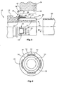
- Fig. 1 is a half-section of a press fitting 10 shown having a fitting body 12 shown only partially from, for example, metallic material (metal alloy, such as brass) with a support sleeve 14.
- metallic material metal alloy, such as brass
- a support sleeve 14 On the support sleeve 14 is concentric with this a plastically deformable compression sleeve 16 of z. B. an aluminum alloy or stainless steel, so that forms an annular space 18 for receiving a pipe 20 to be connected between the compression sleeve 16 and support sleeve 14.
- the support sleeve 14 may have a profiled outer surface and at this a sealing element.
- the compression sleeve 16 has a contact element 22 which is disposed at the end facing away from the free end 24 of the support sleeve 14 thereof.
- the abutment element 22 is used for axial contact and for guiding a pressing tool indicated at 26, which has a pressing surface 28, with which the pressing tool 26 engages from the outside for compression and plastic deformation of the compression sleeve 16.
- the contact element 22 is formed in this embodiment as an abutment ring 30. This is not mandatory. So that could be Investment element 22 also consist of individual longitudinally distributed along the circumference of the compression sleeve 16 arranged individual elements.
- the compression sleeve 16 is preassembled at its free end 24 of the support sleeve 14 opposite retaining end 32 in a manner not to be described on the fitting body 12.
- this pre-assembly can be constructive as in DE 10 2005 028 558 B3 be described, realized.
- the contact ring 30, which is usually made of plastic, has a radially projecting from the compression sleeve 16 bearing surface 34 to which the pressing tool 26, as indicated at 36, abuts when the compression sleeve 16 is deformed. During this deformation process, the pressing surface 28 of the pressing tool 26 acts on the compression sleeve 16 from outside within an action region 38.
- each Verpresskennyogsabêt 40 is substantially U-shaped and provided with two thin legs 50 which are connected to each other via a circumferentially of the compression sleeve 16 extending base member 52.
- the thin legs 50 and the guide notches 46 ensure reliable separation of the Verpresskennyogsabitess 40 and for its destruction during a pressing operation.
- the pressing surface 28 acts on the compression marking portions 40 by being pressed against the compression sleeve 16.
- the compression sleeve 16 is made of a relatively soft metallic material, such as aluminum or an aluminum alloy.
- the Verpresskennyogsabitese 40 are resilient after they are pressed against the compression sleeve 16. By this resilience, the separation or redetachment of the Verpresskennyogsabête 40 and the outer side 42 of the compression sleeve 16 is facilitated.
- the shape of the press-marking portions 40 for realizing a recoverability is, for example, in FIG Fig. 2 to recognize.
- the base parts 52 of the Verpresskennyogyogyogyogyogyogyogyogyogyogyogyogyogyogyogyogyogyogyogyogyogyogyogyogyogyogyogyogyogyogyogyogyogyogyogyogyogyogyogyogyogyogyogyogyogyogyogyogyogyogyogyogyogyogyogyogyogyogyogyogyogyogyogyogyogyogyogyogyogyogyogyogyogyogyogyogyogyogyogyogyogyogyogyogyogyogyogyogyogyogyogyogyogyogyogyogyogyogyogyogyogyogyogyogadosabitese 40 are polygonal or may have a W-structure, wherein they are composed of regions 51 which are spaced differently radially from the compression sleeve 16.
- the base members 52 are pressed by the pressing tool 16 flat against the compression sleeve 16, they deform elastically, so that builds up a restoring force, the base parts 52 can be detached from the outside 42 of the compression sleeve 16 after the pressing tool 26 again from the Press sleeve 16 is spaced.
Landscapes
- Engineering & Computer Science (AREA)
- General Engineering & Computer Science (AREA)
- Mechanical Engineering (AREA)
- Automatic Assembly (AREA)
- Mutual Connection Of Rods And Tubes (AREA)
- Non-Disconnectible Joints And Screw-Threaded Joints (AREA)
- Measuring Fluid Pressure (AREA)
- Clamps And Clips (AREA)
- Pipe Accessories (AREA)
Claims (10)
- Raccord à compression pour un tuyau, en particulier un tuyau en plastique ou un tuyau en matériau composite plastique/métal, comprenant- un corps de raccord (12) qui présente un manchon d'appui (14) sur lequel une extrémité d'un tuyau à raccorder (20) peut être emmanchée,- un manchon de compression (16) qui est déformable plastiquement pour presser contre le manchon d'appui (14) une extrémité d'un tuyau (20) à raccorder emmanchée sur le manchon d'appui (14),- un élément de contact (30) sur le manchon de compression (16), comportant une surface de contact (34) pour l'entrée en contact par un outil de compression (26) en vue de la déformation plastique du manchon de compression (16) et- au moins une section de marquage de compression (40) détachable et saillant de la surface de contact (34) de l'élément de contact (30) et qui s'étend extérieurement sur le manchon de compression (16) jusque dans une zone d'action (38) à l'intérieur de laquelle l'outil de compression (26) entoure le manchon de compression (16) lors de sa déformation,
sachant que- la section de marquage de compression (40) présente une cavité de guidage (44) destinée à recevoir une saillie de guidage (48) de l'outil de compression (26) et/ou une saillie de guidage (48) destinée à être reçue dans une cavité de guidage (44) de l'outil de compression (26) afin d'arrêter axialement le manchon de compression (16) par rapport à l'outil de compression (26) lors de la déformation du manchon de compression (16), sachant que- la section de marquage de compression (40) est détachable de l'élément de contact (30) par l'outil de compression (26) lors de la déformation du manchon de compression (16) de telle manière que l'élément de contact (30) reste sur le manchon de compression (16),- la section de marquage de compression (40) est sensiblement en forme de U et présente deux branches (50) saillant de la surface de contact (34) et une partie de base (52) les reliant, et la partie de base (52) est composée de zones (51) se trouvant radialement à des distances différentes du manchon de compression (16) en forme polygonale. - Raccord à compression selon la revendication 1, caractérisé en ce que la partie de base (52) est composée des zones (51) selon une structure similaire à une lettre W.
- Raccord à compression selon la revendication 1 ou 2, caractérisé en ce que la section de marquage de compression (40) présente, sur son côté extérieur opposé au manchon de compression (16), une surface oblique (43) sur laquelle l'outil de compression (26) peut se déplacer axialement pour l'entrée en contact de l'élément de contact (30).
- Raccord à compression selon l'une des revendications 1 à 3, caractérisé en ce que la cavité de guidage (44) est constituée comme encoche (46) et en ce que l'encoche (46) forme un point de rupture théorique en vue de la séparation de la section de marquage de compression (40) ou d'une partie de celle-ci par l'outil de compression (26) lors de la déformation du manchon de compression (16).
- Raccord à compression selon l'une des revendications 1 à 4, caractérisé en ce que la section de marquage de compression (40) est déformée élastiquement lorqu'elle se trouve appuyée contre le manchon de compression (16) et reprenne d'elle-même sa forme initiale en se détachant du manchon de compression (16).
- Raccord à compression selon l'une des revendications 1 à 5, caractérisé en ce que les zones (51) se trouvant radialement à des distances différentes du manchon de compression (16) sont toutes disposées à distance radiale du manchon de compression (16).
- Raccord à compression selon l'une des revendications 1 à 6, caractérisé en ce qu'une cavité de guidage (44) est constituée dans chaque branche (50).
- Raccord à compression selon l'une des revendications 1 à 7, caractérisé en ce que les zones (51) se trouvant radialement à des distances différentes du manchon de compression (16) sont disposées à l'intérieur de la partie de base (52) de la section de marquage de compression (40).
- Raccord à compression selon l'une des revendications 1 à 8, caractérisé en ce que la partie de base (52) puisse être appuyée à plat contre le manchon de compression au moyen de l'outil de compression (16) de telle manière que la partie de base (52) soit détachable de la face extérieure (42) du manchon de compression (16) moyennant une force de rappel élastique.
- Raccord à compression selon l'une des revendications 1 à 9, caractérisé en ce que l'élément de contact (22) est constitué comme bague de contact (30) qui présente la surface de contact (34).
Priority Applications (2)
| Application Number | Priority Date | Filing Date | Title |
|---|---|---|---|
| PL10196193T PL2292962T3 (pl) | 2007-07-26 | 2007-07-26 | Złączka zaciskowa dla rury |
| DK10196193.6T DK2292962T3 (da) | 2007-07-26 | 2007-07-26 | Presfitting til et rør |
Applications Claiming Priority (1)
| Application Number | Priority Date | Filing Date | Title |
|---|---|---|---|
| EP07113193A EP2019243B1 (fr) | 2007-07-26 | 2007-07-26 | Raccord à sertir pour un tuyau |
Related Parent Applications (1)
| Application Number | Title | Priority Date | Filing Date |
|---|---|---|---|
| EP07113193.2 Division | 2007-07-26 |
Publications (2)
| Publication Number | Publication Date |
|---|---|
| EP2292962A1 EP2292962A1 (fr) | 2011-03-09 |
| EP2292962B1 true EP2292962B1 (fr) | 2012-12-12 |
Family
ID=38800738
Family Applications (2)
| Application Number | Title | Priority Date | Filing Date |
|---|---|---|---|
| EP07113193A Active EP2019243B1 (fr) | 2007-07-26 | 2007-07-26 | Raccord à sertir pour un tuyau |
| EP10196193A Active EP2292962B1 (fr) | 2007-07-26 | 2007-07-26 | Raccord à sertir pour un tuyau |
Family Applications Before (1)
| Application Number | Title | Priority Date | Filing Date |
|---|---|---|---|
| EP07113193A Active EP2019243B1 (fr) | 2007-07-26 | 2007-07-26 | Raccord à sertir pour un tuyau |
Country Status (10)
| Country | Link |
|---|---|
| US (1) | US8936281B2 (fr) |
| EP (2) | EP2019243B1 (fr) |
| AT (1) | ATE498088T1 (fr) |
| CA (1) | CA2637427C (fr) |
| CY (1) | CY1111724T1 (fr) |
| DE (1) | DE502007006461D1 (fr) |
| DK (2) | DK2292962T3 (fr) |
| ES (2) | ES2363855T3 (fr) |
| PL (2) | PL2019243T3 (fr) |
| PT (2) | PT2292962E (fr) |
Families Citing this family (12)
| Publication number | Priority date | Publication date | Assignee | Title |
|---|---|---|---|---|
| AT509561B1 (de) * | 2010-03-04 | 2012-07-15 | Henn Gmbh & Co Kg | Verfahren bei dem ein leitungsverbinder, insbesondere steckverbinder, von einer befestigungsvorrichtung an einer leitung für flüssige und/oder gasförmige medien befestigt wird |
| AT512397B1 (de) * | 2012-05-07 | 2013-08-15 | Henn Gmbh & Co Kg | Steckverbindung zum Verbinden von Leitungen für unter Druck gesetzte Flüssigkeiten oder Gase |
| US9523451B1 (en) * | 2013-02-15 | 2016-12-20 | Elkhart Products Corporation, C/O Aalberts Industries N.V. | Utilizing a visual indicator to determine security of a pipe fitting |
| US9481024B1 (en) | 2013-03-21 | 2016-11-01 | Davor Petricio Yaksic | Pipe joining |
| US10302230B2 (en) | 2014-06-09 | 2019-05-28 | Eaton Intelligent Power Limited | Field serviceable conduit receivers |
| US9551445B2 (en) | 2014-06-09 | 2017-01-24 | Cooper Technologies Company | Conduit receivers |
| DE102017105505A1 (de) * | 2017-03-15 | 2018-09-20 | Viega Technology Gmbh & Co. Kg | Fitting zum Verbinden mit mindestens einem Rohr und Verfahren zum Herstellen einer Verbindung |
| US11088515B2 (en) | 2017-08-31 | 2021-08-10 | Eaton Intelligent Power Limited | Press fitting for electrical conduit |
| DE102018109555B3 (de) | 2018-04-20 | 2019-10-24 | Uponor Innovation Ab | Pressfitting für eine Rohrverbindung und Verfahren zu seiner Herstellung |
| USD888899S1 (en) | 2018-12-21 | 2020-06-30 | Uponor Innovation Ab | Fitting for pipe installations |
| EP4599180A1 (fr) * | 2022-10-06 | 2025-08-13 | Reliance Worldwide Corporation | Emmanchement à la presse |
| USD1103928S1 (en) | 2023-10-06 | 2025-12-02 | Reliance Worldwide Corporation | Connector portion |
Family Cites Families (28)
| Publication number | Priority date | Publication date | Assignee | Title |
|---|---|---|---|---|
| US2679409A (en) * | 1951-01-24 | 1954-05-25 | Scovill Manufacturing Co | Clincher coupling |
| US4225162A (en) * | 1978-09-20 | 1980-09-30 | Amp Incorporated | Liquid tight connector |
| US4270777A (en) * | 1978-11-09 | 1981-06-02 | Trw Inc. | Releasable hose fitting |
| US4564223A (en) * | 1983-05-02 | 1986-01-14 | Parker-Hannifin Corporation | Hose coupling |
| JP2696556B2 (ja) * | 1989-02-23 | 1998-01-14 | ニッタ・ムアー株式会社 | ホース端部取付具及びその取付方法 |
| DE19607630C1 (de) * | 1996-02-29 | 1997-07-31 | Hewing Gmbh | Preßfitting zum Anschluß eines Rohres |
| DE19620165C1 (de) * | 1996-05-08 | 1997-10-16 | Mannesmann Ag | Verfahren und Vorrichtung zum Herstellen einer Rohrpreßverbindung |
| US5772262A (en) * | 1997-04-03 | 1998-06-30 | Rubber-Fab, Inc. | Quick connector for plastic tubing |
| DE19845720C2 (de) | 1998-10-05 | 2001-03-29 | Herz Armaturen Gmbh | Anschlußelement |
| DE19817136C2 (de) | 1998-04-17 | 2000-08-31 | Herz Armaturen Gmbh | Leitungssystem |
| DE29907585U1 (de) | 1998-07-01 | 1999-08-26 | Seppelfricke Gesellschaft für Systemtechnik Heizungssysteme Sanitärsysteme mbH, 48493 Wettringen | Preßfitting für Kunststoffrohre oder Kunststoff/Metall-Verbundrohre |
| DE29915400U1 (de) | 1999-09-02 | 1999-12-09 | Franz Viegener II GmbH & Co. KG, 57439 Attendorn | Fitting oder Armatur zur Erstellung einer Preßverbindung mit einem eingesteckten Rohrende |
| DE29920371U1 (de) | 1999-11-19 | 2000-01-20 | Herz Armaturen Ges.M.B.H., Wien | Anschlußelement |
| DE19955774A1 (de) | 1999-11-19 | 2001-05-31 | Herz Armaturen Gmbh | Anschlußelement |
| DE10022893C1 (de) * | 2000-05-10 | 2001-06-28 | Schuetz Gmbh & Co Kgaa | Pressfitting für Kunststoff-Verbundrohre |
| DE20013425U1 (de) | 2000-08-03 | 2000-12-07 | Mertens, Wilfried, 58706 Menden | Pressfitting |
| DE20207313U1 (de) * | 2002-05-10 | 2003-09-18 | Franz Viegener II GmbH & Co. KG, 57439 Attendorn | Verbindungsstück und Verbindungsanordnung |
| FR2846396B1 (fr) | 2002-10-24 | 2005-05-13 | Comap | Raccord a sertir a securite renforcee |
| DE20300918U1 (de) | 2003-01-22 | 2003-03-20 | Franz Viegener II GmbH & Co. KG, 57439 Attendorn | Pressverbindungsanordnung |
| DK1477719T3 (da) * | 2003-05-13 | 2006-07-10 | Geberit Technik Ag | Forbindelsesanordning til et ledningsrör |
| FR2863032B1 (fr) * | 2003-12-02 | 2006-01-13 | Comap | Raccord a sertir pour tubes multicouches |
| FR2867251B1 (fr) | 2004-03-02 | 2006-04-28 | Comap | Raccord a sertir comprenant une bague de visualisation secable |
| FR2870314B1 (fr) * | 2004-05-14 | 2006-06-23 | Comap Sa | Bague de visualisation du sertissage d'un raccord pour tubes |
| CN2814090Y (zh) * | 2005-03-31 | 2006-09-06 | 佛山市日丰企业有限公司 | 一种钳压式金属管件连接装置 |
| DE102005028558B3 (de) | 2005-06-21 | 2007-01-04 | Uponor Innovation Ab | Pressfitting für ein Rohr |
| PT1790896E (pt) | 2005-11-24 | 2008-10-03 | Uponor Innovation Ab | Encaixe de pressão para um tubo |
| CN200943796Y (zh) * | 2006-09-14 | 2007-09-05 | 佛山市日丰企业有限公司 | 一种卡压式管件 |
| ATE458953T1 (de) * | 2006-12-12 | 2010-03-15 | Uponor Innovation Ab | Pressfitting für ein rohr |
-
2007
- 2007-07-26 DK DK10196193.6T patent/DK2292962T3/da active
- 2007-07-26 EP EP07113193A patent/EP2019243B1/fr active Active
- 2007-07-26 PL PL07113193T patent/PL2019243T3/pl unknown
- 2007-07-26 PT PT101961936T patent/PT2292962E/pt unknown
- 2007-07-26 AT AT07113193T patent/ATE498088T1/de active
- 2007-07-26 DK DK07113193.2T patent/DK2019243T3/da active
- 2007-07-26 ES ES07113193T patent/ES2363855T3/es active Active
- 2007-07-26 PL PL10196193T patent/PL2292962T3/pl unknown
- 2007-07-26 EP EP10196193A patent/EP2292962B1/fr active Active
- 2007-07-26 ES ES10196193T patent/ES2401305T3/es active Active
- 2007-07-26 PT PT07113193T patent/PT2019243E/pt unknown
- 2007-07-26 DE DE502007006461T patent/DE502007006461D1/de active Active
-
2008
- 2008-07-10 CA CA2637427A patent/CA2637427C/fr active Active
- 2008-07-25 US US12/219,638 patent/US8936281B2/en not_active Expired - Fee Related
-
2011
- 2011-05-02 CY CY20111100421T patent/CY1111724T1/el unknown
Also Published As
| Publication number | Publication date |
|---|---|
| DK2292962T3 (da) | 2013-03-18 |
| DE502007006461D1 (de) | 2011-03-24 |
| US8936281B2 (en) | 2015-01-20 |
| PT2019243E (pt) | 2011-05-09 |
| EP2292962A1 (fr) | 2011-03-09 |
| CA2637427C (fr) | 2015-11-24 |
| PL2292962T3 (pl) | 2013-09-30 |
| CY1111724T1 (el) | 2015-10-07 |
| PL2019243T3 (pl) | 2011-07-29 |
| EP2019243A1 (fr) | 2009-01-28 |
| DK2019243T3 (da) | 2011-05-30 |
| CA2637427A1 (fr) | 2009-01-26 |
| PT2292962E (pt) | 2013-03-07 |
| US20090026764A1 (en) | 2009-01-29 |
| EP2019243B1 (fr) | 2011-02-09 |
| ES2363855T3 (es) | 2011-08-18 |
| ATE498088T1 (de) | 2011-02-15 |
| ES2401305T3 (es) | 2013-04-18 |
Similar Documents
| Publication | Publication Date | Title |
|---|---|---|
| EP2292962B1 (fr) | Raccord à sertir pour un tuyau | |
| EP2394087B1 (fr) | Raccord de tuyaux à paroi épaisse et procédé de fabrication dudit raccord | |
| EP2304301B1 (fr) | Ensemble avec une ferrure, un elément de transmission de force et une bague coulissante, ensemble et procédé de fabrication d'une liaison de pièces non détachable | |
| EP0501404A1 (fr) | Dispositif de raccordement pour tuyaux en matière plastique et méthode pour raccorder un tuyau en matière plastique | |
| DE2422919A1 (de) | Verfahren, vorrichtung und selbstboerdelnde mutter zur herstellung von schraubverbindungen | |
| EP2150743B1 (fr) | Element raccord de serrage pour un tuyau | |
| DE202015009132U1 (de) | Fitting zum Verbinden mit einem Rohrelement und Rohrverbindung und ein System zum Verbinden eines Fittings und ein Rohrelement | |
| EP0607610B1 (fr) | Articulation à rotule et procédé pour sa fabrication | |
| DE102014009410A1 (de) | Verfahren zum Verbinden eines Einpressbolzens mit einem ein Vorloch aufweisenden Blechteil und Abdeckelement zur Durchführung des Verfahrens | |
| DE10319376B4 (de) | Pressbacke für ein Presswerkzeug zum Verpressen von Fittingen, Presswerkzeug und Werkzeug zum axialen Aufschieben einer Hülse | |
| EP1441165B1 (fr) | Raccord à sertir | |
| EP1267113B1 (fr) | Elément de raccordement | |
| DE4243213C1 (de) | Verfahren zur Festlegung einer Hülse in einem Rohr unter Verwendung von mehreren Ringen aus einer Formgedächtnislegierung und Einrichtung zur Herstellung eines Ringes | |
| DE29711313U1 (de) | Preßverbindung | |
| EP1306601B1 (fr) | Raccords à compression pour la connection d'au moins un tuyau | |
| EP1126206B1 (fr) | Raccord de compression pour tuyaux | |
| DE202007007827U1 (de) | Klemmfitting für ein Rohr | |
| EP2886923A1 (fr) | Racord de tuyau pour des conduites de tuyaux hydrauliques avec joint périphérique | |
| DE102018104793A1 (de) | Dichtungsring zur Abdichtung von Flanschverbindungen | |
| DE19748623A1 (de) | Preßverbindung | |
| DE102015120509A1 (de) | Schlauchschelle | |
| EP1377397A2 (fr) | Outil d'assemblage par rivetage | |
| DE4444857C1 (de) | Verfahren und Vorrichtung zur Herstellung mindestens einer Öffnung in der Wandung eines rohrartigen Teils | |
| EP0180656B1 (fr) | Raccords pour joindre des tubes en matières fragiles | |
| DE19727642A1 (de) | Preßverbindung |
Legal Events
| Date | Code | Title | Description |
|---|---|---|---|
| PUAI | Public reference made under article 153(3) epc to a published international application that has entered the european phase |
Free format text: ORIGINAL CODE: 0009012 |
|
| AC | Divisional application: reference to earlier application |
Ref document number: 2019243 Country of ref document: EP Kind code of ref document: P |
|
| AK | Designated contracting states |
Kind code of ref document: A1 Designated state(s): AT BE BG CH CY CZ DE DK EE ES FI FR GB GR HU IE IS IT LI LT LU LV MC MT NL PL PT RO SE SI SK TR |
|
| 17P | Request for examination filed |
Effective date: 20110822 |
|
| 17Q | First examination report despatched |
Effective date: 20111011 |
|
| GRAP | Despatch of communication of intention to grant a patent |
Free format text: ORIGINAL CODE: EPIDOSNIGR1 |
|
| RIN1 | Information on inventor provided before grant (corrected) |
Inventor name: DITTMAR, RAINER Inventor name: BECKMANN, STEFAN Inventor name: KERN, THOMAS |
|
| GRAS | Grant fee paid |
Free format text: ORIGINAL CODE: EPIDOSNIGR3 |
|
| GRAA | (expected) grant |
Free format text: ORIGINAL CODE: 0009210 |
|
| AC | Divisional application: reference to earlier application |
Ref document number: 2019243 Country of ref document: EP Kind code of ref document: P |
|
| AK | Designated contracting states |
Kind code of ref document: B1 Designated state(s): AT BE BG CH CY CZ DE DK EE ES FI FR GB GR HU IE IS IT LI LT LU LV MC MT NL PL PT RO SE SI SK TR |
|
| REG | Reference to a national code |
Ref country code: GB Ref legal event code: FG4D Free format text: NOT ENGLISH |
|
| REG | Reference to a national code |
Ref country code: CH Ref legal event code: EP |
|
| REG | Reference to a national code |
Ref country code: AT Ref legal event code: REF Ref document number: 588498 Country of ref document: AT Kind code of ref document: T Effective date: 20121215 |
|
| REG | Reference to a national code |
Ref country code: IE Ref legal event code: FG4D Free format text: LANGUAGE OF EP DOCUMENT: GERMAN |
|
| RAP2 | Party data changed (patent owner data changed or rights of a patent transferred) |
Owner name: UPONOR INNOVATION AB |
|
| REG | Reference to a national code |
Ref country code: DE Ref legal event code: R096 Ref document number: 502007011045 Country of ref document: DE Effective date: 20130207 |
|
| REG | Reference to a national code |
Ref country code: PT Ref legal event code: SC4A Free format text: AVAILABILITY OF NATIONAL TRANSLATION Effective date: 20130226 |
|
| REG | Reference to a national code |
Ref country code: RO Ref legal event code: EPE |
|
| REG | Reference to a national code |
Ref country code: CH Ref legal event code: NV Representative=s name: PATENTANWALTSKANZLEI NUECKEL, CH |
|
| REG | Reference to a national code |
Ref country code: DK Ref legal event code: T3 |
|
| REG | Reference to a national code |
Ref country code: SE Ref legal event code: TRGR |
|
| REG | Reference to a national code |
Ref country code: NL Ref legal event code: T3 |
|
| REG | Reference to a national code |
Ref country code: ES Ref legal event code: FG2A Ref document number: 2401305 Country of ref document: ES Kind code of ref document: T3 Effective date: 20130418 |
|
| PG25 | Lapsed in a contracting state [announced via postgrant information from national office to epo] |
Ref country code: LT Free format text: LAPSE BECAUSE OF FAILURE TO SUBMIT A TRANSLATION OF THE DESCRIPTION OR TO PAY THE FEE WITHIN THE PRESCRIBED TIME-LIMIT Effective date: 20121212 |
|
| REG | Reference to a national code |
Ref country code: LT Ref legal event code: MG4D |
|
| PG25 | Lapsed in a contracting state [announced via postgrant information from national office to epo] |
Ref country code: LV Free format text: LAPSE BECAUSE OF FAILURE TO SUBMIT A TRANSLATION OF THE DESCRIPTION OR TO PAY THE FEE WITHIN THE PRESCRIBED TIME-LIMIT Effective date: 20121212 Ref country code: GR Free format text: LAPSE BECAUSE OF FAILURE TO SUBMIT A TRANSLATION OF THE DESCRIPTION OR TO PAY THE FEE WITHIN THE PRESCRIBED TIME-LIMIT Effective date: 20130313 Ref country code: SI Free format text: LAPSE BECAUSE OF FAILURE TO SUBMIT A TRANSLATION OF THE DESCRIPTION OR TO PAY THE FEE WITHIN THE PRESCRIBED TIME-LIMIT Effective date: 20121212 |
|
| PG25 | Lapsed in a contracting state [announced via postgrant information from national office to epo] |
Ref country code: EE Free format text: LAPSE BECAUSE OF FAILURE TO SUBMIT A TRANSLATION OF THE DESCRIPTION OR TO PAY THE FEE WITHIN THE PRESCRIBED TIME-LIMIT Effective date: 20121212 Ref country code: BG Free format text: LAPSE BECAUSE OF FAILURE TO SUBMIT A TRANSLATION OF THE DESCRIPTION OR TO PAY THE FEE WITHIN THE PRESCRIBED TIME-LIMIT Effective date: 20130312 Ref country code: SK Free format text: LAPSE BECAUSE OF FAILURE TO SUBMIT A TRANSLATION OF THE DESCRIPTION OR TO PAY THE FEE WITHIN THE PRESCRIBED TIME-LIMIT Effective date: 20121212 Ref country code: IS Free format text: LAPSE BECAUSE OF FAILURE TO SUBMIT A TRANSLATION OF THE DESCRIPTION OR TO PAY THE FEE WITHIN THE PRESCRIBED TIME-LIMIT Effective date: 20130412 |
|
| REG | Reference to a national code |
Ref country code: PL Ref legal event code: T3 |
|
| PLBE | No opposition filed within time limit |
Free format text: ORIGINAL CODE: 0009261 |
|
| STAA | Information on the status of an ep patent application or granted ep patent |
Free format text: STATUS: NO OPPOSITION FILED WITHIN TIME LIMIT |
|
| 26N | No opposition filed |
Effective date: 20130913 |
|
| PG25 | Lapsed in a contracting state [announced via postgrant information from national office to epo] |
Ref country code: CY Free format text: LAPSE BECAUSE OF FAILURE TO SUBMIT A TRANSLATION OF THE DESCRIPTION OR TO PAY THE FEE WITHIN THE PRESCRIBED TIME-LIMIT Effective date: 20121212 |
|
| REG | Reference to a national code |
Ref country code: DE Ref legal event code: R097 Ref document number: 502007011045 Country of ref document: DE Effective date: 20130913 |
|
| PG25 | Lapsed in a contracting state [announced via postgrant information from national office to epo] |
Ref country code: MC Free format text: LAPSE BECAUSE OF FAILURE TO SUBMIT A TRANSLATION OF THE DESCRIPTION OR TO PAY THE FEE WITHIN THE PRESCRIBED TIME-LIMIT Effective date: 20121212 |
|
| REG | Reference to a national code |
Ref country code: IE Ref legal event code: MM4A |
|
| PG25 | Lapsed in a contracting state [announced via postgrant information from national office to epo] |
Ref country code: IE Free format text: LAPSE BECAUSE OF NON-PAYMENT OF DUE FEES Effective date: 20130726 |
|
| PG25 | Lapsed in a contracting state [announced via postgrant information from national office to epo] |
Ref country code: MT Free format text: LAPSE BECAUSE OF FAILURE TO SUBMIT A TRANSLATION OF THE DESCRIPTION OR TO PAY THE FEE WITHIN THE PRESCRIBED TIME-LIMIT Effective date: 20121212 Ref country code: TR Free format text: LAPSE BECAUSE OF FAILURE TO SUBMIT A TRANSLATION OF THE DESCRIPTION OR TO PAY THE FEE WITHIN THE PRESCRIBED TIME-LIMIT Effective date: 20121212 |
|
| PG25 | Lapsed in a contracting state [announced via postgrant information from national office to epo] |
Ref country code: LU Free format text: LAPSE BECAUSE OF NON-PAYMENT OF DUE FEES Effective date: 20130726 Ref country code: HU Free format text: LAPSE BECAUSE OF FAILURE TO SUBMIT A TRANSLATION OF THE DESCRIPTION OR TO PAY THE FEE WITHIN THE PRESCRIBED TIME-LIMIT; INVALID AB INITIO Effective date: 20070726 |
|
| REG | Reference to a national code |
Ref country code: FR Ref legal event code: PLFP Year of fee payment: 10 |
|
| REG | Reference to a national code |
Ref country code: FR Ref legal event code: PLFP Year of fee payment: 11 |
|
| REG | Reference to a national code |
Ref country code: CH Ref legal event code: PCAR Free format text: NEW ADDRESS: OBERDORFSTRASSE 16, 8820 WAEDENSWIL (CH) |
|
| REG | Reference to a national code |
Ref country code: FR Ref legal event code: PLFP Year of fee payment: 12 |
|
| PGFP | Annual fee paid to national office [announced via postgrant information from national office to epo] |
Ref country code: AT Payment date: 20210722 Year of fee payment: 15 |
|
| REG | Reference to a national code |
Ref country code: AT Ref legal event code: MM01 Ref document number: 588498 Country of ref document: AT Kind code of ref document: T Effective date: 20220726 |
|
| PG25 | Lapsed in a contracting state [announced via postgrant information from national office to epo] |
Ref country code: AT Free format text: LAPSE BECAUSE OF NON-PAYMENT OF DUE FEES Effective date: 20220726 |
|
| P01 | Opt-out of the competence of the unified patent court (upc) registered |
Effective date: 20230602 |
|
| PGFP | Annual fee paid to national office [announced via postgrant information from national office to epo] |
Ref country code: NL Payment date: 20250721 Year of fee payment: 19 |
|
| PGFP | Annual fee paid to national office [announced via postgrant information from national office to epo] |
Ref country code: FI Payment date: 20250725 Year of fee payment: 19 Ref country code: PT Payment date: 20250717 Year of fee payment: 19 Ref country code: ES Payment date: 20250826 Year of fee payment: 19 |
|
| PGFP | Annual fee paid to national office [announced via postgrant information from national office to epo] |
Ref country code: DK Payment date: 20250725 Year of fee payment: 19 Ref country code: DE Payment date: 20250722 Year of fee payment: 19 |
|
| PGFP | Annual fee paid to national office [announced via postgrant information from national office to epo] |
Ref country code: IT Payment date: 20250721 Year of fee payment: 19 Ref country code: PL Payment date: 20250718 Year of fee payment: 19 |
|
| PGFP | Annual fee paid to national office [announced via postgrant information from national office to epo] |
Ref country code: GB Payment date: 20250722 Year of fee payment: 19 Ref country code: BE Payment date: 20250721 Year of fee payment: 19 |
|
| PGFP | Annual fee paid to national office [announced via postgrant information from national office to epo] |
Ref country code: FR Payment date: 20250725 Year of fee payment: 19 |
|
| PGFP | Annual fee paid to national office [announced via postgrant information from national office to epo] |
Ref country code: CH Payment date: 20250801 Year of fee payment: 19 Ref country code: SE Payment date: 20250722 Year of fee payment: 19 |
|
| PGFP | Annual fee paid to national office [announced via postgrant information from national office to epo] |
Ref country code: CZ Payment date: 20250718 Year of fee payment: 19 |
|
| PGFP | Annual fee paid to national office [announced via postgrant information from national office to epo] |
Ref country code: RO Payment date: 20250722 Year of fee payment: 19 |