EP2292994A2 - Appareil frigorifique doté d'un compartiment de machines à ventilation forcée - Google Patents
Appareil frigorifique doté d'un compartiment de machines à ventilation forcée Download PDFInfo
- Publication number
- EP2292994A2 EP2292994A2 EP10169465A EP10169465A EP2292994A2 EP 2292994 A2 EP2292994 A2 EP 2292994A2 EP 10169465 A EP10169465 A EP 10169465A EP 10169465 A EP10169465 A EP 10169465A EP 2292994 A2 EP2292994 A2 EP 2292994A2
- Authority
- EP
- European Patent Office
- Prior art keywords
- refrigerating appliance
- air outlet
- appliance according
- machine room
- air
- Prior art date
- Legal status (The legal status is an assumption and is not a legal conclusion. Google has not performed a legal analysis and makes no representation as to the accuracy of the status listed.)
- Withdrawn
Links
- 238000001816 cooling Methods 0.000 claims abstract description 12
- 238000005057 refrigeration Methods 0.000 claims description 3
- 238000011144 upstream manufacturing Methods 0.000 claims description 2
- 239000003570 air Substances 0.000 description 36
- 238000001704 evaporation Methods 0.000 description 3
- 230000008020 evaporation Effects 0.000 description 3
- 238000009423 ventilation Methods 0.000 description 3
- XLYOFNOQVPJJNP-UHFFFAOYSA-N water Substances O XLYOFNOQVPJJNP-UHFFFAOYSA-N 0.000 description 3
- 238000009413 insulation Methods 0.000 description 2
- 239000012080 ambient air Substances 0.000 description 1
- 230000001174 ascending effect Effects 0.000 description 1
- 238000009833 condensation Methods 0.000 description 1
- 230000005494 condensation Effects 0.000 description 1
- 238000010276 construction Methods 0.000 description 1
- 238000007598 dipping method Methods 0.000 description 1
- 238000007599 discharging Methods 0.000 description 1
- 238000001035 drying Methods 0.000 description 1
- 230000000694 effects Effects 0.000 description 1
- 230000002349 favourable effect Effects 0.000 description 1
- 238000010438 heat treatment Methods 0.000 description 1
- 230000007774 longterm Effects 0.000 description 1
- 239000000463 material Substances 0.000 description 1
- 230000004048 modification Effects 0.000 description 1
- 238000012986 modification Methods 0.000 description 1
- 230000001376 precipitating effect Effects 0.000 description 1
- 238000001556 precipitation Methods 0.000 description 1
- 239000006200 vaporizer Substances 0.000 description 1
Images
Classifications
-
- F—MECHANICAL ENGINEERING; LIGHTING; HEATING; WEAPONS; BLASTING
- F25—REFRIGERATION OR COOLING; COMBINED HEATING AND REFRIGERATION SYSTEMS; HEAT PUMP SYSTEMS; MANUFACTURE OR STORAGE OF ICE; LIQUEFACTION SOLIDIFICATION OF GASES
- F25D—REFRIGERATORS; COLD ROOMS; ICE-BOXES; COOLING OR FREEZING APPARATUS NOT OTHERWISE PROVIDED FOR
- F25D23/00—General constructional features
- F25D23/003—General constructional features for cooling refrigerating machinery
-
- F—MECHANICAL ENGINEERING; LIGHTING; HEATING; WEAPONS; BLASTING
- F25—REFRIGERATION OR COOLING; COMBINED HEATING AND REFRIGERATION SYSTEMS; HEAT PUMP SYSTEMS; MANUFACTURE OR STORAGE OF ICE; LIQUEFACTION SOLIDIFICATION OF GASES
- F25D—REFRIGERATORS; COLD ROOMS; ICE-BOXES; COOLING OR FREEZING APPARATUS NOT OTHERWISE PROVIDED FOR
- F25D21/00—Defrosting; Preventing frosting; Removing condensed or defrost water
- F25D21/04—Preventing the formation of frost or condensate
-
- F—MECHANICAL ENGINEERING; LIGHTING; HEATING; WEAPONS; BLASTING
- F25—REFRIGERATION OR COOLING; COMBINED HEATING AND REFRIGERATION SYSTEMS; HEAT PUMP SYSTEMS; MANUFACTURE OR STORAGE OF ICE; LIQUEFACTION SOLIDIFICATION OF GASES
- F25D—REFRIGERATORS; COLD ROOMS; ICE-BOXES; COOLING OR FREEZING APPARATUS NOT OTHERWISE PROVIDED FOR
- F25D23/00—General constructional features
- F25D23/10—Arrangements for mounting in particular locations, e.g. for built-in type, for corner type
-
- F—MECHANICAL ENGINEERING; LIGHTING; HEATING; WEAPONS; BLASTING
- F25—REFRIGERATION OR COOLING; COMBINED HEATING AND REFRIGERATION SYSTEMS; HEAT PUMP SYSTEMS; MANUFACTURE OR STORAGE OF ICE; LIQUEFACTION SOLIDIFICATION OF GASES
- F25D—REFRIGERATORS; COLD ROOMS; ICE-BOXES; COOLING OR FREEZING APPARATUS NOT OTHERWISE PROVIDED FOR
- F25D2323/00—General constructional features not provided for in other groups of this subclass
- F25D2323/002—Details for cooling refrigerating machinery
- F25D2323/0021—Details for cooling refrigerating machinery using air guides
-
- F—MECHANICAL ENGINEERING; LIGHTING; HEATING; WEAPONS; BLASTING
- F25—REFRIGERATION OR COOLING; COMBINED HEATING AND REFRIGERATION SYSTEMS; HEAT PUMP SYSTEMS; MANUFACTURE OR STORAGE OF ICE; LIQUEFACTION SOLIDIFICATION OF GASES
- F25D—REFRIGERATORS; COLD ROOMS; ICE-BOXES; COOLING OR FREEZING APPARATUS NOT OTHERWISE PROVIDED FOR
- F25D2323/00—General constructional features not provided for in other groups of this subclass
- F25D2323/002—Details for cooling refrigerating machinery
- F25D2323/0026—Details for cooling refrigerating machinery characterised by the incoming air flow
- F25D2323/00264—Details for cooling refrigerating machinery characterised by the incoming air flow through the front bottom part
-
- F—MECHANICAL ENGINEERING; LIGHTING; HEATING; WEAPONS; BLASTING
- F25—REFRIGERATION OR COOLING; COMBINED HEATING AND REFRIGERATION SYSTEMS; HEAT PUMP SYSTEMS; MANUFACTURE OR STORAGE OF ICE; LIQUEFACTION SOLIDIFICATION OF GASES
- F25D—REFRIGERATORS; COLD ROOMS; ICE-BOXES; COOLING OR FREEZING APPARATUS NOT OTHERWISE PROVIDED FOR
- F25D2323/00—General constructional features not provided for in other groups of this subclass
- F25D2323/002—Details for cooling refrigerating machinery
- F25D2323/0027—Details for cooling refrigerating machinery characterised by the out-flowing air
- F25D2323/00271—Details for cooling refrigerating machinery characterised by the out-flowing air from the back bottom
-
- F—MECHANICAL ENGINEERING; LIGHTING; HEATING; WEAPONS; BLASTING
- F25—REFRIGERATION OR COOLING; COMBINED HEATING AND REFRIGERATION SYSTEMS; HEAT PUMP SYSTEMS; MANUFACTURE OR STORAGE OF ICE; LIQUEFACTION SOLIDIFICATION OF GASES
- F25D—REFRIGERATORS; COLD ROOMS; ICE-BOXES; COOLING OR FREEZING APPARATUS NOT OTHERWISE PROVIDED FOR
- F25D2323/00—General constructional features not provided for in other groups of this subclass
- F25D2323/002—Details for cooling refrigerating machinery
- F25D2323/0027—Details for cooling refrigerating machinery characterised by the out-flowing air
- F25D2323/00274—Details for cooling refrigerating machinery characterised by the out-flowing air from the front bottom
-
- F—MECHANICAL ENGINEERING; LIGHTING; HEATING; WEAPONS; BLASTING
- F25—REFRIGERATION OR COOLING; COMBINED HEATING AND REFRIGERATION SYSTEMS; HEAT PUMP SYSTEMS; MANUFACTURE OR STORAGE OF ICE; LIQUEFACTION SOLIDIFICATION OF GASES
- F25D—REFRIGERATORS; COLD ROOMS; ICE-BOXES; COOLING OR FREEZING APPARATUS NOT OTHERWISE PROVIDED FOR
- F25D2500/00—Problems to be solved
- F25D2500/02—Geometry problems
Definitions
- the present invention relates to a refrigerating appliance, in particular a household refrigerating appliance, with an engine room arranged under the carcass.
- the body To prevent moisture from precipitating on the outside of the refrigerated body, the body must be designed so that its surface temperature never goes below the dew point. This requires either a sufficient thickness of the insulation layer of the body or, in places that can not be sufficiently isolated, especially in the area between a front of the body and the door of the device, an additional heating of the vulnerable surface areas.
- the omission of the back wall condenser makes it possible to set up a refrigeration device with the machine room arranged under the carcass very close to a building or furniture wall. If this wall is itself good heat insulating, it contributes to the insulation of the refrigerator, with the result that the temperature in the gap between the rear wall of the device and the building or furniture wall can fall below the dew point. So moisture in the gap can condense, which does not evaporate or at best very slowly due to the narrowness of the gap. In the long term, this may result in damage to the device, the wall or adjacent furniture. The same problem arises, even without the wall in front of the device is good heat insulating when the device is placed in a warm environment with high humidity, especially in tropical climates.
- the object of the present invention is to provide a refrigerator with a body and a machine room arranged under the body, in which the risk of precipitation of condensation on the back of the device or one of these back wall opposite is eliminated.
- the object is achieved by having in a refrigerator with a body and an under the body engine room containing a compressor, a condenser and a fan and having a front inlet and at least one outlet for cooling air, a downstream of the fan overpressure area of the engine room adjacent to a rear wall of the engine room, in which at least one outlet is formed.
- the forced air circulation of the fan forces a draft of air along the rear of the unit.
- guide elements are preferably arranged in the outlet for deflecting the exiting air flow upwards.
- the air guide elements are curved.
- the at least one air outlet is elongated and extends in the width direction of the engine room.
- the at least one air outlet is formed in a removable cover, which covers at least the overpressure region of the engine room largely.
- a particularly favorable distribution of the device rear side over the cover flowing air stream results when a plurality of air outlets are provided on the cover distributed over the surface and have guide elements.
- Each of these air outlets then has an air guide element for guiding the air flow upwards.
- the rear wall of the engine room is also expediently flush with the rear side of the carcass.
- the at least one air outlet on the rear wall of the machine room has an air outlet cross-sectional area which is smaller or at most equal to the air outlet cross-sectional area of the air outlet provided at the front of the machine room.
- the sum of the air outlet cross-sectional areas is smaller or at most equal to the air outlet area of the air outlet provided at the front of the machine room.
- the greater part of the cooling air flow exits at the front of the engine room.
- the condenser is preferably located in a vacuum region of the engine room upstream of the fan so that the entire flow of cooling air is drawn across the condenser.
- a vaporizer for condensed water inside the appliance is preferably exposed to the partial flow passing through the compressor.
- the fan is expediently arranged in an intermediate wall between the vacuum region and the overpressure region of the machine room.
- the engine room is at such a Built-in device preferably accommodates space saving in a base unit, which, when the device is mounted in a piece of furniture, engages through a cutout in a bottom plate of the furniture in the base area.
- Subject of the invention is therefore also an arrangement of a kitchen furniture and built into a niche of the kitchen refrigerator of the type described above, in which the body is on a bottom plate of the furniture niche and dipping the base unit through a section of the bottom plate in the base region of the kitchen cabinet.
- the cutout to the back of the niche is open.
- the distance between the rear wall of the body and the back of the furniture recess is preferably less than 20 mm.
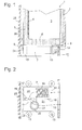
- Fig. 1 shows a vertical section through a built-in household refrigeration appliance according to the invention and a furniture niche in which the device is received.
- the refrigerator has a cuboid housing with a body 1 and a door 2, which define a heat-insulated storage chamber 3 in a conventional manner.
- an evaporator 4 is embedded, which essentially cools the storage chamber 3, but which can also lead to a suitable ambient climate that the Temperature on the outside of the rear wall 5 drops below the dew point and can condense humidity.
- a substantially cuboidal base unit 7 is mounted, the internal structure with respect to Fig. 2 respectively.
- Fig. 3 will be explained in more detail.
- a niche of a kitchen furniture, in which the device is mounted, has parallel to the cutting plane, not shown side walls and a bottom plate 8, on which the body 1 of the device rests.
- the niche is bounded behind by a wall 25 of a building in front of which the furniture is placed; Alternatively, the wall 25 could also be part of the furniture itself.
- the wall 25 and the rear wall 5 of the refrigerator limit a gap 26 with a maximum depth of 20 mm.
- a base portion 10 below the bottom plate 8 is closed at the front by a bar 11 in which a vent 12 is recessed.
- the bottom plate 8 is supported in a conventional manner by height-adjustable feet 13.
- a recess 9 is cut in the bottom plate 8. The recess 9 is open towards a rear edge of the bottom plate 8, so that the gap 26 extends continuously through the recess 9 into the base region 10.
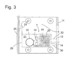
- Fig. 2 shows in a schematic horizontal section the internal structure of the base unit 7 according to a first embodiment.
- two large-area openings form an inlet 14 and an outlet 15 for cooling air.
- a grid, fins or the like stretched over the openings prevent a user from inadvertently coming into contact with voltage-carrying components in the base unit 7.
- the interior of the base unit 7 is divided by a running in the depth direction intermediate wall 16 into two chambers.
- a fan 18 is arranged in one of a rear wall 17 of the base unit 7 adjacent region of the intermediate wall 16 in which a fan 18 is arranged.
- a condenser 19 is in the suction side of Fan 18 located chamber 20 housed; the pressure-side chamber 21 includes a compressor 22.
- the rear wall 17, which is formed in the present embodiment as a cover, is removable in order to access the chambers 20, 21 for assembly or repair purposes.
- the part of the rear wall 17 which closes the chamber 20 is free of openings; in which the chamber 21 closing part openings are formed, preferably in the form of a plurality of parallel horizontal slots 23, wherein between the slots 23 left standing material of the rear wall 17 is deflected to widen the slots 23 and between them slanted slats 24 (see Fig. 1 ) to deflect the air exiting through the slots 23 upwards.
- a portion of the circulated by the fan 18 cooling air is diverted after passing the condenser 19 and sweeps the back wall 17 and the flush adjoining the rear wall 5 of the body 1 up.
- a collecting channel for condensing water on the evaporator 4 is formed at the bottom of the evaporator 4 in a conventional manner.
- the water is discharged from the gutter into an evaporation tray 27 which is mounted on and heated by the evaporator 22. Since the ascending air in the gap 26 branches off before passing through the evaporation tray 27, steam does not get from there into the gap 26, but is blown through the outlet 15 and the ventilation opening 12 directly into the open.
- Fig. 3 shows a modification of the base unit 7, in which the two chambers 20, 21 are arranged with the evaporator 19 and the compressor 22 in the depth direction one behind the other and a single outlet 28 is formed on the back of the base unit 7.
- the entire cooling air flow is passed over the evaporator 19 and the compressor 22.
- a predominant part of the exiting at the outlet 28 cooling air flows through cavities of the base portion 10 below the base unit 7 or laterally from this back to the front and exits at the vent opening 12 again.
- Further guide walls 30 may be provided between the inlet 14 of the base unit and the vent opening 12 to ensure that used cooling air exits via the vent opening 12 and is not immediately sucked back into the inlet 14.
Landscapes
- Engineering & Computer Science (AREA)
- Chemical & Material Sciences (AREA)
- Combustion & Propulsion (AREA)
- Physics & Mathematics (AREA)
- Mechanical Engineering (AREA)
- Thermal Sciences (AREA)
- General Engineering & Computer Science (AREA)
- Devices That Are Associated With Refrigeration Equipment (AREA)
Applications Claiming Priority (1)
| Application Number | Priority Date | Filing Date | Title |
|---|---|---|---|
| DE102009027882A DE102009027882A1 (de) | 2009-07-21 | 2009-07-21 | Kältegerät mit zwangsbelüftetem Maschinenraum |
Publications (2)
| Publication Number | Publication Date |
|---|---|
| EP2292994A2 true EP2292994A2 (fr) | 2011-03-09 |
| EP2292994A3 EP2292994A3 (fr) | 2017-10-04 |
Family
ID=42989583
Family Applications (1)
| Application Number | Title | Priority Date | Filing Date |
|---|---|---|---|
| EP10169465.1A Withdrawn EP2292994A3 (fr) | 2009-07-21 | 2010-07-14 | Appareil frigorifique doté d'un compartiment de machines à ventilation forcée |
Country Status (2)
| Country | Link |
|---|---|
| EP (1) | EP2292994A3 (fr) |
| DE (1) | DE102009027882A1 (fr) |
Cited By (1)
| Publication number | Priority date | Publication date | Assignee | Title |
|---|---|---|---|---|
| CN117308442A (zh) * | 2022-06-23 | 2023-12-29 | 青岛海尔电冰箱有限公司 | 冰箱及其通风格栅组件 |
Families Citing this family (3)
| Publication number | Priority date | Publication date | Assignee | Title |
|---|---|---|---|---|
| TR201106344A2 (tr) * | 2011-06-27 | 2013-01-21 | Arçeli̇k Anoni̇m Şi̇rketi̇ | Makina odası içeren bir buzdolabı. |
| DE102012008268A1 (de) * | 2012-04-18 | 2013-10-24 | Liebherr-Hausgeräte Ochsenhausen GmbH | Kühl- und/oder Gefriergerät |
| KR20210110975A (ko) * | 2020-03-02 | 2021-09-10 | 엘지전자 주식회사 | 공간 배치형 냉장고 시스템 |
Citations (3)
| Publication number | Priority date | Publication date | Assignee | Title |
|---|---|---|---|---|
| US4089187A (en) * | 1975-06-23 | 1978-05-16 | General Electric Company | Condenser-air flow system of a household refrigerator |
| JP2000154964A (ja) * | 1998-11-20 | 2000-06-06 | Fujitsu General Ltd | 冷蔵庫 |
| TW200643355A (en) * | 2005-06-09 | 2006-12-16 | Toshiba Kk | Refrigerator |
Family Cites Families (5)
| Publication number | Priority date | Publication date | Assignee | Title |
|---|---|---|---|---|
| DE19907077A1 (de) * | 1999-02-19 | 2000-08-24 | Bsh Bosch Siemens Hausgeraete | Kältegerät für den Einbau in eine Möbelnische |
| JP4140122B2 (ja) * | 1999-03-23 | 2008-08-27 | 三菱電機株式会社 | 冷蔵庫 |
| JP2001272159A (ja) * | 2000-03-27 | 2001-10-05 | Sanden Corp | 冷却ユニット |
| JP2004205061A (ja) * | 2002-12-24 | 2004-07-22 | Hoshizaki Electric Co Ltd | 冷凍装置 |
| KR100506605B1 (ko) * | 2003-05-09 | 2005-08-08 | 삼성전자주식회사 | 냉장고 |
-
2009
- 2009-07-21 DE DE102009027882A patent/DE102009027882A1/de not_active Withdrawn
-
2010
- 2010-07-14 EP EP10169465.1A patent/EP2292994A3/fr not_active Withdrawn
Patent Citations (3)
| Publication number | Priority date | Publication date | Assignee | Title |
|---|---|---|---|---|
| US4089187A (en) * | 1975-06-23 | 1978-05-16 | General Electric Company | Condenser-air flow system of a household refrigerator |
| JP2000154964A (ja) * | 1998-11-20 | 2000-06-06 | Fujitsu General Ltd | 冷蔵庫 |
| TW200643355A (en) * | 2005-06-09 | 2006-12-16 | Toshiba Kk | Refrigerator |
Cited By (1)
| Publication number | Priority date | Publication date | Assignee | Title |
|---|---|---|---|---|
| CN117308442A (zh) * | 2022-06-23 | 2023-12-29 | 青岛海尔电冰箱有限公司 | 冰箱及其通风格栅组件 |
Also Published As
| Publication number | Publication date |
|---|---|
| EP2292994A3 (fr) | 2017-10-04 |
| DE102009027882A1 (de) | 2011-01-27 |
Similar Documents
| Publication | Publication Date | Title |
|---|---|---|
| EP2694894B1 (fr) | Dispositif combiné de refrigeration | |
| CH635190A5 (de) | Verfahren zum kuehllagern und frischhalten von frischprodukten sowie kuehlmoebel zur ausfuehrung des verfahrens. | |
| EP2433063B1 (fr) | Appareil frigorifique sans givre | |
| DE69001559T2 (de) | Einbauhaushaltskühlschrank. | |
| EP2697578B1 (fr) | Appareil frigorifique comportant un bac d'évaporation | |
| EP2292994A2 (fr) | Appareil frigorifique doté d'un compartiment de machines à ventilation forcée | |
| EP2473804B1 (fr) | Appareil frigorifique comprenant un récipient encastrable | |
| DE102017213972A1 (de) | Kältegerät mit Verdunstungsschale | |
| DE102011075564A1 (de) | Verdunstungsvorrichtung für ein Einbaukältegerät sowie Einbaukältegerät und Verfahren zum Einbau eines Einbaukältegeräts | |
| WO2006058819A1 (fr) | Appareil frigorifique encastrable | |
| DE102017005226A1 (de) | Sockelkonzept | |
| DE102010003088A1 (de) | Kältegerät mit Tauwasserverdunster | |
| WO2006058821A1 (fr) | Appareil frigorifique | |
| DE102009028781A1 (de) | Kältegerät mit Tauwasser-Auffangrinne | |
| DE102016211438A1 (de) | Kältegerät | |
| DE102016210708A1 (de) | No-Frost-Kältegerät | |
| DE102016224389A1 (de) | No-Frost-Haushaltskältegerät mit zur Rückwand dichtender Trennplatte | |
| DE2724880A1 (de) | Kastenfoermiger, an einen schaltschrank vorzugsweise ansetzbarer kuehler | |
| EP2249109A2 (fr) | Appareil de refroidissement, notamment appareil de refroidissement ménager doté d'une rainure pour eau de condensation | |
| CH708943A1 (de) | Kühlgerät mit Kondensationsschutz. | |
| EP3225943A1 (fr) | Appareil de réfrigération et/ou de congélation | |
| DE8123465U1 (de) | Kuehlaggregat fuer elektrische schaltschraenke | |
| DE1451046A1 (de) | Tiefkuehlschrank fuer Selbstbedienung | |
| WO2012130624A2 (fr) | Appareil frigorifique à ventilateur axial | |
| DE8133007U1 (de) | Gefriergeraet, insbesondere gefrierschrank oder dergleichen |
Legal Events
| Date | Code | Title | Description |
|---|---|---|---|
| PUAI | Public reference made under article 153(3) epc to a published international application that has entered the european phase |
Free format text: ORIGINAL CODE: 0009012 |
|
| AK | Designated contracting states |
Kind code of ref document: A2 Designated state(s): AL AT BE BG CH CY CZ DE DK EE ES FI FR GB GR HR HU IE IS IT LI LT LU LV MC MK MT NL NO PL PT RO SE SI SK SM TR |
|
| AX | Request for extension of the european patent |
Extension state: BA ME RS |
|
| RAP1 | Party data changed (applicant data changed or rights of an application transferred) |
Owner name: BSH HAUSGERAETE GMBH |
|
| PUAL | Search report despatched |
Free format text: ORIGINAL CODE: 0009013 |
|
| AK | Designated contracting states |
Kind code of ref document: A3 Designated state(s): AL AT BE BG CH CY CZ DE DK EE ES FI FR GB GR HR HU IE IS IT LI LT LU LV MC MK MT NL NO PL PT RO SE SI SK SM TR |
|
| AX | Request for extension of the european patent |
Extension state: BA ME RS |
|
| RIC1 | Information provided on ipc code assigned before grant |
Ipc: F25D 21/04 20060101ALI20170830BHEP Ipc: F25D 23/10 20060101ALI20170830BHEP Ipc: F25D 23/00 20060101AFI20170830BHEP |
|
| 17P | Request for examination filed |
Effective date: 20180404 |
|
| RBV | Designated contracting states (corrected) |
Designated state(s): AL AT BE BG CH CY CZ DE DK EE ES FI FR GB GR HR HU IE IS IT LI LT LU LV MC MK MT NL NO PL PT RO SE SI SK SM TR |
|
| GRAP | Despatch of communication of intention to grant a patent |
Free format text: ORIGINAL CODE: EPIDOSNIGR1 |
|
| INTG | Intention to grant announced |
Effective date: 20191007 |
|
| STAA | Information on the status of an ep patent application or granted ep patent |
Free format text: STATUS: THE APPLICATION IS DEEMED TO BE WITHDRAWN |
|
| 18D | Application deemed to be withdrawn |
Effective date: 20200218 |