EP2295887A2 - Réservoir d'eau avec élément d'étanchéité - Google Patents
Réservoir d'eau avec élément d'étanchéité Download PDFInfo
- Publication number
- EP2295887A2 EP2295887A2 EP10008744A EP10008744A EP2295887A2 EP 2295887 A2 EP2295887 A2 EP 2295887A2 EP 10008744 A EP10008744 A EP 10008744A EP 10008744 A EP10008744 A EP 10008744A EP 2295887 A2 EP2295887 A2 EP 2295887A2
- Authority
- EP
- European Patent Office
- Prior art keywords
- inner cylinder
- cover
- cylinder
- engaged
- edge
- Prior art date
- Legal status (The legal status is an assumption and is not a legal conclusion. Google has not performed a legal analysis and makes no representation as to the accuracy of the status listed.)
- Withdrawn
Links
- XLYOFNOQVPJJNP-UHFFFAOYSA-N water Substances O XLYOFNOQVPJJNP-UHFFFAOYSA-N 0.000 title claims abstract description 135
- 238000007789 sealing Methods 0.000 title claims abstract description 125
- 238000012856 packing Methods 0.000 claims description 49
- 238000003466 welding Methods 0.000 claims description 40
- 230000002787 reinforcement Effects 0.000 claims description 29
- 230000003811 curling process Effects 0.000 claims description 20
- 239000012774 insulation material Substances 0.000 claims description 19
- 239000000463 material Substances 0.000 claims description 18
- 238000005452 bending Methods 0.000 claims description 3
- 238000009413 insulation Methods 0.000 description 13
- 238000000034 method Methods 0.000 description 10
- 239000007769 metal material Substances 0.000 description 8
- 238000010438 heat treatment Methods 0.000 description 6
- XUIMIQQOPSSXEZ-UHFFFAOYSA-N Silicon Chemical compound [Si] XUIMIQQOPSSXEZ-UHFFFAOYSA-N 0.000 description 5
- 229910052710 silicon Inorganic materials 0.000 description 5
- 239000010703 silicon Substances 0.000 description 5
- 238000003860 storage Methods 0.000 description 5
- XAGFODPZIPBFFR-UHFFFAOYSA-N aluminium Chemical compound [Al] XAGFODPZIPBFFR-UHFFFAOYSA-N 0.000 description 4
- 229910052782 aluminium Inorganic materials 0.000 description 4
- 229910001220 stainless steel Inorganic materials 0.000 description 4
- 239000010935 stainless steel Substances 0.000 description 4
- 229910010293 ceramic material Inorganic materials 0.000 description 3
- 238000004140 cleaning Methods 0.000 description 3
- 238000010276 construction Methods 0.000 description 3
- 238000001816 cooling Methods 0.000 description 3
- 238000005260 corrosion Methods 0.000 description 3
- 230000000694 effects Effects 0.000 description 3
- 238000005265 energy consumption Methods 0.000 description 3
- 239000012212 insulator Substances 0.000 description 3
- 230000008569 process Effects 0.000 description 3
- JOYRKODLDBILNP-UHFFFAOYSA-N Ethyl urethane Chemical compound CCOC(N)=O JOYRKODLDBILNP-UHFFFAOYSA-N 0.000 description 2
- 229920006328 Styrofoam Polymers 0.000 description 2
- 239000000498 cooling water Substances 0.000 description 2
- 230000007797 corrosion Effects 0.000 description 2
- 238000007599 discharging Methods 0.000 description 2
- 239000006260 foam Substances 0.000 description 2
- 239000008236 heating water Substances 0.000 description 2
- 239000004033 plastic Substances 0.000 description 2
- 239000002210 silicon-based material Substances 0.000 description 2
- 239000008261 styrofoam Substances 0.000 description 2
- 239000000126 substance Substances 0.000 description 2
- 238000007792 addition Methods 0.000 description 1
- 230000000703 anti-shock Effects 0.000 description 1
- 235000013361 beverage Nutrition 0.000 description 1
- 230000015572 biosynthetic process Effects 0.000 description 1
- 239000000919 ceramic Substances 0.000 description 1
- 230000006835 compression Effects 0.000 description 1
- 238000007906 compression Methods 0.000 description 1
- 239000000470 constituent Substances 0.000 description 1
- 210000003298 dental enamel Anatomy 0.000 description 1
- 239000003651 drinking water Substances 0.000 description 1
- 235000020188 drinking water Nutrition 0.000 description 1
- 229920001971 elastomer Polymers 0.000 description 1
- 239000000945 filler Substances 0.000 description 1
- 239000011521 glass Substances 0.000 description 1
- 238000002347 injection Methods 0.000 description 1
- 239000007924 injection Substances 0.000 description 1
- 238000007689 inspection Methods 0.000 description 1
- 238000009434 installation Methods 0.000 description 1
- 238000012423 maintenance Methods 0.000 description 1
- 244000005700 microbiome Species 0.000 description 1
- 238000012986 modification Methods 0.000 description 1
- 230000004048 modification Effects 0.000 description 1
- 238000012545 processing Methods 0.000 description 1
- 239000002994 raw material Substances 0.000 description 1
- 230000009467 reduction Effects 0.000 description 1
- 239000003507 refrigerant Substances 0.000 description 1
- 239000005060 rubber Substances 0.000 description 1
- 230000007480 spreading Effects 0.000 description 1
- 238000003892 spreading Methods 0.000 description 1
- 238000006467 substitution reaction Methods 0.000 description 1
- 229920003051 synthetic elastomer Polymers 0.000 description 1
- 239000005061 synthetic rubber Substances 0.000 description 1
- 238000007666 vacuum forming Methods 0.000 description 1
- 238000005493 welding type Methods 0.000 description 1
Images











Classifications
-
- F—MECHANICAL ENGINEERING; LIGHTING; HEATING; WEAPONS; BLASTING
- F24—HEATING; RANGES; VENTILATING
- F24H—FLUID HEATERS, e.g. WATER OR AIR HEATERS, HAVING HEAT-GENERATING MEANS, e.g. HEAT PUMPS, IN GENERAL
- F24H1/00—Water heaters, e.g. boilers, continuous-flow heaters or water-storage heaters
- F24H1/18—Water-storage heaters
- F24H1/20—Water-storage heaters with immersed heating elements, e.g. electric elements or furnace tubes
- F24H1/208—Water-storage heaters with immersed heating elements, e.g. electric elements or furnace tubes with tubes filled with heat transfer fluid
-
- F—MECHANICAL ENGINEERING; LIGHTING; HEATING; WEAPONS; BLASTING
- F24—HEATING; RANGES; VENTILATING
- F24H—FLUID HEATERS, e.g. WATER OR AIR HEATERS, HAVING HEAT-GENERATING MEANS, e.g. HEAT PUMPS, IN GENERAL
- F24H1/00—Water heaters, e.g. boilers, continuous-flow heaters or water-storage heaters
- F24H1/18—Water-storage heaters
- F24H1/181—Construction of the tank
Definitions
- the present invention relates to a water tank with a sealing element. More particularly, the present invention relates to a water tank with a sealing element, which facilitates its assembling, improves a sealing force in diverse manners, and makes it possible to clean the interior of the water tank.
- a water tank is provided, and it is general that the water tank is made of a metallic material, such as stainless steel, aluminum, or the like, for convenience in heat resistance, anti-corrosion, anti-shock performance, durability, and formation.
- Such a water tank is generally composed of a body and a cover, and in order to secure sealing between the body and the cover, welding may be performed.
- a crack or water leak phenomenon may occur due to the vulnerability occurring along a welded region between the body and the cover, and materials that are harmful to a human body may occur due to the corrosion of the corresponding region in the case where the water tank is used for a long time.
- a microorganism may propagate itself, and an alien substance such as fur may form in the interior of the water tank, so that it is required to clean the interior of the water tank.
- the water tank is mainly made of a metallic material that has a high thermal conductivity, the heat is easily released to the outside. Accordingly, even if the water in the water tank is heated or cooled at a desired temperature, the temperature of the water in the water tank readily gets similar to the ambient temperature, and thus it is required that the water in the water tank is continuously heated or cooled to cause the energy consumption.
- the present invention has been made to solve the above-mentioned problems occurring in the prior art while advantages achieved by the prior art are maintained intact.
- the present invention is related to the providing of a water tank having a sealing element, which achieves an accurate sealing.
- the present invention is related to the providing of a water tank having a sealing element, which facilitates the cleaning of the interior of the water tank and achieves an accurate sealing.
- the present invention is related to the providing of a water tank having a sealing element, which can minimize the energy consumption for heating or cooling water in the water tank through heightening of the heat insulation performance.
- a water tank which includes a body which has one open side and accommodates water therein; a cover which finishes the body and has a temperature control member that heats or cools the water accommodated in the body; and a sealing portion for making the body and the cover mutually engaged with each other to seal up the interior of the body.
- the sealing portion has a structure that includes a first bent portion which is inserted into an inner wall of an expanded tube portion formed along an edge on an open side of the cylindrical body and is formed along an edge of the cover so as to form a valley that is parallel to the inner wall; and a second bent portion which extends from the first bent portion, is engaged with the expanded tube portion through a curling process, and is compressed along an outer wall of the body.
- the body includes an inner cylinder that accommodates the water and an outer cylinder that forms a space portion in association with an outer surface of the inner cylinder and surrounds the inner cylinder, the cover finishes the inner cylinder and the outer cylinder, and the sealing portion is mounted between the inner cylinder and the cover or between the outer cylinder and the cover to keep a sealing state between the inner cylinder and the outer cylinder.
- the outer cylinder is integrally engaged with the edge on one open side of the inner cylinder, and a vacuum state is maintained between an inner surface of the outer cylinder and an outer surface of the inner cylinder.
- the water tank having a sealing element according to the present invention has the following advantages.
- the sealing force can be improved by a curling process in a state where the cover and the body are firmly fixed during their processing without shaking.
- the body has a double structure including an inner cylinder having a vacuum space portion formed therein and an outer cylinder, the heat insulation performance can be improved and thus the power consumption for heating or cooling the water can be reduced.
- the cover and the body adopt a detachable sealing structure, the cleaning of the water tank can be easily performed.
- FIG. 1 is a perspective view illustrating the whole structure of a water tank with a sealing element according to an embodiment of the present invention
- FIG. 2 is a perspective view illustrating the whole structure of a water tank with a sealing element according to another embodiment of the present invention
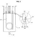
- FIG. 3 is a conceptual sectional view of FIG. 2 .
- a water tank with a sealing element has a structure that briefly includes a body 10 and a cover 300, and the body 10 and the cover 300 are mutually engaged with each other by a sealing portion 400 to seal up the interior of the body 10.
- the body 10 is a portion one side of which is open to accommodate water therein and which provides a space where the cover 300 to be described later and the sealing portion 400 are installed.
- an unexplained reference numeral "101" denotes a drain tube.
- the cover 300 finishes the body 10, and is a portion in which a temperature control member 301 that heats or cools the water accommodated in the body 10 by a heat source supplied from the outside, and a thermostat (not illustrated) that keeps the water temperature that is adjusted by the temperature control member 301 are installed.
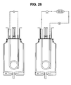
- the temperature control member 301 may be a heater (see left drawing of FIG. 26 ) that heats the water accommodated in the body 10 by power supply from the outside or a cooling tube (see right drawing of FIG. 26 ) in which a refrigerant of a cooling cycle, which is supplied from the outside to circulate, flows.
- the thermostat is typically mounted on a fixing frame 160 provided on the external surface of the body 10 as illustrated in FIG. 2 to adjust the temperature of the water accommodated in the body 10, and although being described in various embodiments to be described later, it is mounted preferably on the cover 300 because of the sealing of a space portion 900 provided in the body 10 to form the vacuum state.
- 303 denotes a fixing bracket
- 304 denotes a water inlet tube
- 305 denotes a water outlet tube
- 306 denotes a temperature sensor, which are mounted on the cover 300.
- the sealing portion 400 serves to make the body 10 and the cover 300 mutually engaged with each other to seal up to interior of the body 10, and embodiments of the present invention to which the sealing portion is applied in diverse manners will be described in more detail.
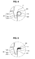
- the sealing portion 400 is to seal up the interior of the body 10 by making the body 10 and the cover 300 mutually engaged with each other, and as illustrated in FIGS 2 to 5 , it has a structure including a first bent portion 401 and a second bent portion 405.
- the other sealed side and wall surface portion of the body are integrally formed by a drawing process, and this is because in the case of making them engaged with each other by a method such as welding or the like, leakage may occur in an engagement portion or drinking water may be polluted due to the corrosion of the engagement portion.
- An expanded tube portion 140 is a portion that is formed by bending an edge of one open side of the body to the outside and expanding the edge, and is engaged with the second bent portion 405.
- the first bent portion 401 is inserted into an inner wall of the expanded tube portion 140 formed along the edge on the open side of the cylindrical body 10, and is formed along an edge of the cover 300 so as to form a valley 307 that is parallel to the inner wall.
- the first bent portion 401 is a portion from which the second bent portion 405 extends.
- the second bent portion 405 extends from the first bent portion 401, is engaged with the expanded tube portion 140 through a curling process, and is compressed along an outer wall of the body 10 to maintain the sealing state of the body 10.
- the first bent portion 401 may adopt a structure that includes the other side wall 402, a bottom 403, and one side wall 404 to form the valley 307.
- the other side wall 402 is slantingly bent from the inner wall of the body along the edge of the cover 300
- the bottom 403 extends in parallel to the cover 300 from an end portion of the other side wall 402 to the inner wall of the body 10
- the one side wall 404 extends from the edge of the bottom 403 and is bent to be in contact with the inner wall of the body 10.
- the second bent portion 405 extends from the one side wall 404 and is engaged with the expanded tube portion 140.
- the second bent portion 405 is engaged with the expanded tube portion 140, it forms a circular cross section along the outer wall of the body 10 as shown in FIG. 4 , becomes in close contact with the outer wall of the body 10 as shown in FIG. 3 , or surrounds the end portion of the expanded tube portion 140 as shown in FIG. 5 .
- the first bent portion 401 is press-fit engaged with the inner wall of the body 10 by the above-described structure, and the other side wall 402 slantingly formed has a strong elastic repulsion force against a pressure applied from the edge of the cover 300, i.e. applied from the edge of the outer wall of the body 10.
- the body 10 and the cover 300 are firmly fixed to each other, and thus the end portion of the first bent portion 401 and the expanded tube portion 140 can clearly and prominently form the sealing portion 400 including the second bent portion 405 without movement or misalignment during the curling process.
- a packing material P intervenes along a portion in which the body 10 and the cover 300 become in contact with each other, i.e. along a direction in which the sealing portion is formed, and the packing material P seals even a minute gap that may occur between the body 10 and the cover 300 to prevent the leakage of water.
- the packing material P may typically be a material such as silicon.
- a worker can form the sealing portion 400 by fixing the body 10 and the cover 300 to each other, spreading silicon between the second bent portion 405 and the expanded tube portion 140, and performing a curling process after the silicon is dried.
- FIGS. 6 to 14 embodiments of the present invention are illustrated in FIGS. 6 to 14 .
- the body 10 has a double wall structure composed of an inner cylinder 100 and an outer cylinder 200, and the inner cylinder 100 and the outer cylinder 200 are made of a metallic material such as aluminum, stainless steel, or the like.
- the inner cylinder 100 which is briefly in the form of a cylinder, has one open side, and is provided with a water storage space formed therein.
- the outer cylinder 200 which is briefly in the form of a cylinder, has a diameter that is larger than that of the inner cylinder 100, and is arranged to accommodate the inner cylinder 100 therein.
- the outer cylinder 200 is arranged to surround the outer side of the inner cylinder 100, and a gap that corresponds to a difference in diameter between the inner cylinder 100 and the outer cylinder 200 is formed between the inner cylinder 100 and the outer cylinder 200.
- Open end portions of the inner cylinder 100 and the outer cylinder 200 are mutually bonded in a body, and thus an airtight space portion as wide as the gap is formed between the inner cylinder 100 and the outer cylinder 200.
- the bonding type of end portions of the inner cylinder 100 and the outer cylinder 200 may be welding.
- the airtight space portion 900 functions as a heat insulation layer to keep the hot water stored in the inner cylinder 100 warm.
- an air layer may be formed in the space portion 900, and in order to maximize the warmth keeping efficiency of the hot water stored in the hot water tank, the space portion 900 may be in a vacuum state or a heat insulation material may fill in the space portion 900.
- a hole for vacuum exhaust is formed on the outer cylinder 200, and the inner cylinder 100 and the outer cylinder 200 bonded in a body is put in a vacuum heating furnace to be vacuum-heated. By sealing the vacuum exhaust hole when the vacuum state reaches a predetermined level, the vacuum state of the space portion 900 is formed.
- a vacuum exhaust device is connected to the vacuum exhaust hole to perform the vacuum exhaust, and by sealing the vacuum exhaust hole when the vacuum state reaches a predetermined level, the vacuum state of the space portion 900 is formed.
- a heat insulation material may fill in the space portion 900, and in this case, the heat insulation material may be a heat insulation material having an excellent heat insulation performance, such as Styrofoam, foam urethane, or the like, or a heat insulation material that considers even the flammability.
- the filling of the heat insulation material means the filling of the heat insulation material in the space portion in a manner that a heat insulation material that tightly surrounds the outer surface of the inner cylinder 100 is formed, the inner cylinder and the heat insulation material in this state are accommodated in the outer cylinder 200 so that the outer surface of the heat insulation material is closely surrounded by the inner surface of the outer cylinder 200, and the end portions of the inner cylinder 100 and the outer cylinder 200 are bonded in a body.
- the cover 300 is also made of a metallic material such as aluminum, stainless steel, or the like, and one open side of the body 10, and specifically one open side of the inner cylinder 100, is covered by the cover 300 to seal the inner water storage space of the inner cylinder 100.
- the cover 300 may be engaged with the body 10 by making the edge of the cover engaged with the edge of the open side of the body 10 using a curling process or welding.
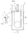
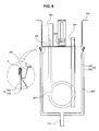
- FIG. 6 illustrates an example of a curling process. Specifically, the edge region of the open side of the body 10, i.e. the region in which the outer cylinder 200 and the inner cylinder 100 are mutually bonded in a body, is bent outwardly of the body 10, and the edge region of the cover 300 pressingly surrounds the bent edge region of the body 10.
- the curling process is not limited to the above-described examples, and can be curling-processed in diverse shapes as illustrated in FIGS. 7 to 10 .
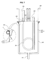
- FIG. 7 shows an example of a curling process in which the edge region of the cover 300 is curled up on the edge region of the open side of the body 10, so that the vertical cross section of the mutually engaged region of the body 10 and the cover 300 is briefly in the form of a circle.
- FIG. 8 illustrates an example of a curling process in which the mutually engaged region of the cover 300 and the body 10 is bent downward once more and becomes in close contact with the outer surface of the outer cylinder 200 in the example of the curling process as illustrated in FIG. 6 .
- the cover 300 may be engaged with the body 10 as the edge region of the cover 300 is welded onto the edge region of the open side of the body 10, and diverse welding types such as examples in FIGS. 9 and 10 may be presented.
- the edge on the open side of the body 10 is formed to be bent outwardly of the body 10, and the edge region of the cover 300 is bent to be in close contact with an inner periphery of the upper end of the inner cylinder 100 and the upper surface of the bent portion, so that the cover 300 covers the open side of the body 10 as if the cover 300 is inserted into the interior of the body 10, the end of the edge of the cover 300 and the end of the edge on the open side of the body 10 are neighbored to be in contact with each other, and these regions are engaged with each other in welding.
- an outwardly bent region is formed on the edge region on the open side of the body 10, and the cover 300 covers the open side of the body 10 as if the cover 300 is put on the open side of the body 10, so that the end of the edge of the cover 300 and the end of the edge on the open side of the body 10 are neighbored to be in contact with each other, and these regions are engaged with each other in welding.
- a packing P is interposed between the engaged portions of the cover 300 and the body 10 mutually engaged with each other.
- the packing P is included to secure the airtight of the water storage space in the hot water tank, and is made of synthetic rubber or a silicon material.
- the above-described curling process or welding is performed in a state where the packing P is interposed between the mutually engaged regions of the body 10 and the cover 300.
- FIGS. 6 to 10 illustrate an example of a temperature control member 301 such as a pipe heater that is penetratingly engaged with one side of the cover 300 so as to be connected to the water storage space of the body 10, specifically, the water storage space in the inner cylinder 100.
- a temperature control member 301 such as a pipe heater that is penetratingly engaged with one side of the cover 300 so as to be connected to the water storage space of the body 10, specifically, the water storage space in the inner cylinder 100.
- a temperature sensor 306 for measuring the temperature of the water stored in the body 10 is provided, and as illustrated, the temperature sensor 306 is provided on the surface of the cover 300.
- the positions where the temperature control member 301 and the temperature sensor 306 are installed in the water tank including the body 10 and the cover 300 are not limited to the examples as illustrated, and the temperature control member 301 and the temperature sensor 306 may be installed in diverse positions.
- the water tank having the above-described water tank may be fixed by a fixing bracket 303 in the interior of the hot/cold water dispenser, water purifier, vending machine, or the like.
- the fixing bracket 303 is provided in the cover 300 in a state where the one open side of the body 10 is directed upward.
- the installation position of the fixing bracket 303 and the direction of the open side of the body 10 are not limited to those in the illustrated examples.
- the body 10 may be engaged with the cover 300 in a state where the open side of the body 10 is directed downward, and the fixing bracket 303 may be installed in diverse positions as needed.
- the unexplained reference numerals "304" and “305” denote a water inlet tube and a water outlet tube, respectively, provided in a general hot water tank, and "101" denotes a drain tube.
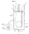
- the present invention is applicable by the embodiment as illustrated in FIG. 11 .
- the hot water tank does not have a structure in which the body 10 and the cover 300 are not engaged with each other, but has a structure in which an upper body 10u and a lower body 10d are engaged with each other.
- a cylindrical upper body 10u having an open lower side and a cylindrical lower body 10d which has an open upper side and which is engaged with the lower edge of the upper body 10u in welding are included. Also, a packing P is interposed between mutual engagement regions of the upper body 10u and the lower body 10d.
- the upper body 10u and the lower body 10d in this embodiment have a double wall structure in the same manner as the body 10 in the above-described embodiments.
- the upper body 10u and the lower body 10d include cylindrical inner cylinders 100u and 100d having open sides (in the case of the inner cylinder 100u included on one side (the upper body 10u), they mean lower sides, while in the case of the inner cylinder 100d included on the lower body 10d, they mean upper sides) and cylindrical outer cylinders 200u and 200d arranged as if they surround the inner cylinders 100u and 100d.
- the respective end portions of the inner cylinders 100u and 100d and the outer cylinders 200u and 200d are mutually bonded in a body, and an airtight space portion 900 is formed between the inner cylinders 100u and 100d and the outer cylinders 200u and 200d.
- the airtight space portion 900 may be in a vacuum state or may be filled with a heat insulation material for an efficient heat insulation of the hot water tank in the same manner as the first embodiment.
- FIG. 11 shows a state where edges of the upper body 10u and the lower body 10d are engaged with each other in welding.
- the engagement type is not limited thereto, and in the same manner as the above-described examples, the upper body 10u and the lower body 10d may be engaged with each other by a curling process.
- the present invention is applicable by the embodiments as illustrated in FIGS 12 and 13 .
- the body 10 and the cover 300 are separably engaged with each other.
- the body 10 included in this embodiment has a double wall structure in the same manner as the above-described embodiments with reference to FIGS. 6 to 10 .
- a heat insulation material having an excellent heat insulation performance such as Styrofoam, foam urethane, or the like, or a heat insulation material that considers even the flammability may fill in the space portion 900 between the inner cylinder 100 and the outer cylinder 200.
- a body engagement portion 10c that is formed on an outer periphery on the open side of the body 10 along a circumferential direction is further included, and on the outer periphery of the body engagement portion 10c, a thread 100s is formed.
- the cover 300 that is engaged to cover the open side of the body 10 further includes a cover engagement portion 300c which is formed on the outer periphery along the circumferential direction and which can be screw-engaged with the body engagement portion 10c, and on an inner periphery of the cover engagement portion 300c, a screw groove 300s which can be screw-engaged with the thread 100s of the body engagement portion 10c is formed.
- the body engagement portion 10c and the cover engagement portion 300c are formed on the body 10 and the cover 300, respectively, to be screw-engaged with each other, the body 10 and the cover 300 can be separably engaged with each other.
- a packing P may be interposed between the edge on the open side of the body 10 and the edge of the cover 300 to secure the airtight in the body 10.
- a bent portion that is bent outwardly in the form of an arc may be formed on the respective edge portions of the body 10 and the cover to widen the area that presses the packing P.
- the packing P as shown in FIG. 12 , has a plurality of protrusions 300p formed on the outer periphery of the packing P in a circumferential direction, and thus the airtight performance between the body 10 and the cover 300 can be further improved.
- the packing P has a locking piece 300h, which is twice bent downward at right angles in the circumferential direction, formed thereon to be locked in the edge of the end portion of the body 10, and thus the engagement and disengagement of the packing P is facilitated during the assembling and disassembling of the packing.
- the separable structure further includes the body engagement portion 10c and the cover engagement portion 300c, the body 10 and the cover 300 are not required to be engaged with each other by the mutual curling process or welding as in the embodiments illustrated in FIGS. 6 to 11 , and thus the material is not limited to a metallic material.
- the body 10 and the cover 300 may be made of a metallic material or a ceramic material.
- the body engagement portion 10c and the cover engagement portion 300c are made of a plastic material in a state where the body 10 and the cover 300 are made of a metallic material, the body engagement portion 10c and the cover engagement portion 300c may be engaged with the body 10 and the cover 300, respectively, by an insert injection or a press-fit engagement method.
- protrusion shaped structures may be provided on the outer peripheries of the body 10 and the cover 300, respectively.
- the body engagement portion 10c and the cover engagement portion 300c may also be made of a ceramic material to be formed in a body.
- the inner cylinder 100 and the outer cylinder 200 of the body 10 are not bonded in a body by welding or the like, but are formed in a body so that the space portion 900 is formed between the inner cylinder 100 and the outer cylinder 200.
- a flammable or inflammable heat insulation material 300i having a high flammability and a high heat insulation performance, which is covered by an upper portion of the cover 300 to minimize a loss of the heat energy of the water accommodated in the body 10 through the cover 300, may be further included.
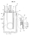
- the present invention can adopt the structure as illustrated in FIG. 14 .
- the hot water tank has a structure in which the cover 300 and the body 10 are separably engaged with each other by a screw engagement method.
- the structure of the cover 300 is the same as that in the third embodiment, but the structure of the body 10 differs from that in the third embodiment.
- the structure of the body 10 which is different from that according to the third embodiment, will be described in a state where unexplained reference numerals in the drawing are substituted by the explanation in the above-described embodiments.
- the body 10 in the same manner as the embodiments as illustrated in FIGS. 6 to 13 , has a double wall structure that includes the inner cylinder 100 and the outer cylinder 200. However, end portions of the inner cylinder 100 and the outer cylinder 200 are not bonded in a body, but the outer cylinder 200 is fit-engaged with the body engagement portion 10c formed on the outer periphery of the inner periphery.
- the body engagement portion 10c having the same function as that in the embodiments as illustrated in FIGS. 12 and 13 is formed.
- a fitting portion 100sb extending downward at right angles is formed along the circumferential direction of the body engagement portion 10c.
- the outer cylinder 200 is fit-engaged with the fitting portion 100sb as the outer periphery of the fitting portion 100sb becomes in surface contact with the inner periphery of the end portion on the open side of the outer cylinder 200.
- fitting protrusion 100sbp is formed to project (in FIG. 14 , an example in which two fitting protrusions 100sbp that are spaced apart in upward and downward directions are formed on the outer periphery of the fitting portion 100sb), and corresponding to the fitting protrusion, fitting grooves 100g are formed on the inner periphery of the end portion of the outer cylinder 200.
- the outer cylinder 200 and the fitting portion 100sb can be firmly and stably fit-engaged with each other as the outer cylinder 200 easily finds its position by the fitting grooves 100g and the fitting protrusions 100sbp inserted into the fitting grooves 100g, respectively.
- the space portion 900 between the outer cylinder 200 and the inner cylinder 100 is formed as wide as the gap formed between the fitting portion 100sp and the inner cylinder 100, and is in a vacuum state or is filled with a heat insulation material.
- the packing P is interposed along the border of the open side of the inner cylinder 100 and the edge that is bent outwardly in the form of an arc from the edge of the cover 300.
- the body 10 may adopt a double structure to improve the heat insulation performance as shown in FIGS. 15 to 26 , and specifically, may adopt a structure that includes the inner cylinder 100 and the outer cylinder 200.
- the inner cylinder 100 provides a space for accommodating the water
- the outer cylinder 200 has a structure in which the space portion 900 is formed between the outer cylinder 200 and the outer surface of the inner cylinder 100 as surrounding the inner cylinder 100.
- the cover 300 to be described later finishes the inner cylinder 100 and the outer cylinder 200
- the sealing portion 400 is installed between the inner cylinder 100 and the cover 300 or between the outer cylinder 200 and the cover 300 to keep the sealing state of the inner cylinder 100 and the outer cylinder 200.
- the outer cylinder 200 is engaged with the edge of one open side of the inner cylinder 100, and it is preferable that a gap between the inner surface of the outer cylinder 200 and the outer surface of the inner cylinder 100 is kept in a vacuum state to improve the heat insulation performance.
- the inner cylinder 100 and the outer cylinder 200 may be made of a metallic material such as stainless steel, aluminum, or the like in consideration of the convenience in forming, durability, and the like.
- the inner cylinder 100 and the outer cylinder 200 may be made of diverse materials such as glass, ceramics, enamel, and the like.
- the outer surface of the outer cylinder 200 has the lowest thermal conductivity, and thus the water accommodated in the inner cylinder 100 can be kept hot or cool.
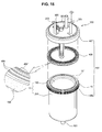
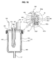
- the sealing portion 400 may adopt a structure that includes a first engagement member 406, a second engagement member 407, and a packing 408, as shown in FIGS. 15 and 16 , in the body 10 that has the double structure including the inner cylinder 100 and the outer cylinder 200.
- first engagement member 406 is engaged with the outer side of the edge of the outer cylinder 200 and has a screw portion 406s formed along the outer periphery thereof.
- the second engagement member 407 is engaged with the outer surface of the cover 300 and has a screw portion 407s formed along the inner periphery thereof to be screw-engaged with the first engagement member 406.
- the packing 408 is interposed between the end portion of the body 10 and the edge on the inner side of the cover 300 and serves to make the interior of the body 10 airtight.
- support protrusions 200p are formed to protrude along the outer periphery of the outer cylinder 200 to support one side of the first engagement member 406, and support protrusions 300p are formed to protrude along the outer periphery of the cover 300 to support one side of the second engagement member 407.
- the second engagement member 407 when the cover 300 and the body 100 are engaged with each other, surrounds the first engagement member 406 so that the screw portions 406s and 407s are screw-engaged with each other.
- the packing 408 is made of a rubber or silicon material, and has diverse shapes including an O-ring of which the vertical cross section is "O"-shaped.
- a third bent portion 15 that is bent to the outside to be engaged with the packing 408 may be formed, and as shown in FIG. 16 , end portions on the open sides of the inner cylinder 100 and the outer cylinder 200 are bent in a body to form the third bent portion 15.
- FIG. 16 shows the structure of the projection portion 15' projecting from the third bent portion 15.
- the packing 408 has a vertical cross section briefly in a " ⁇ "-shaped so that the lower side of the packing 408 is engaged with the end portion of the outer side of the third bent portion 15. Since the packing 408 is fit-engaged to cover the upper surface of the third bent portion 15, it can be easily detached when the body 10 is cleaned.
- the packing 408 has at least one ring-shaped protrusion flange 409 formed along a surface opposite to the third bent portion 15 or the fourth bent portion 35 toward the third bent portion 15 or the fourth bent portion 35, and a plurality of small protrusions 408' formed apart from one another on the interior or exterior of the protrusion flange 409 along the surface opposite to the third bent portion 15 or the fourth bent portion 35, so that the fastening force between the body 10 and the cover 300 can be strengthened.
- an extension portion 409' that extends in upward and downward directions is integrally formed on the end portion of the interior of the packing 408, being in contact with the edges of the interiors of the body 10 and the cover 300, to secure the sealing more accurately.
- the airtight performance of the body 10 can be reinforced.
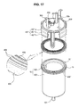
- the sealing portion 400 may adopt a structure that includes a locking portion 406', a fastening portion 407', and the packing 408 as shown in FIGS. 17 and 18 .
- the fastening portion 407' includes a fixing member 407'a and a wing 407'b having a locking piece 407'h formed thereon, and is engaged with the locking portion 406'.
- the packing 408 is interposed between the end portion of the body 10 and the edge on the interior of the cover 300, and serves to make the interior of the body 10 airtight.
- the fixing member 407'a of the fastening portion 407' is fixed to the outer surface of the cover 300, and the wing 407'b rotatably extends along the edge of the fixing member 407'a, and the locking piece 407'h that is engaged with the locking protrusion 406'p projects toward the outer side of the outer cylinder 200.
- the fixing member 407'a and the wing 407'b are connected by diverse connection methods such as hinge engagement (not illustrated) by a hinge pin.
- the fastening portion 407' is made of a material such as plastic, and the connection region of the fixing member 407'a and the wing 407'b is made to be thin, so that the connection region has a rotatable integral structure in upward and downward directions.
- the locking piece 407'h is locked in the locking protrusion 406'p to achieve the engagement, and when the wing 407'b becomes far from the outer surface of the body 10, more particularly, from the exterior of the outer cylinder 200, the engagement is released.
- the straight distance from the connection point of the fixing member 407'a and the wing 407'b to the locking piece 407'h is somewhat shorter than the distance to the lower end of the locking protrusion 406'p formed on the outer side of the bottom portion of the locking portion 406' on the horizontal line at the same position, and thus the locking piece 223 is locked as it passes through the lower end of the locking protrusion 406'p.
- fastening portions 407' are formed along the edge of the cover 300, and another fastening portion 407' is provided in a position opposite to one fastening portion 407' so that the convenience is given to the rotation of the wing 407' and the compression force by the fastening portion 407' is uniformly given along the outer surface of the outer cylinder 200.
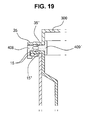
- the third bent portion 15 and the fourth bent portion 35 may adopts a structure as shown in FIG. 10 .
- grooves 15" and 35" are formed on the third bent portion 15 and the fourth bent portion 35, respectively, and both edges of the grooves 15" and 35" have the shape of projection regions.
- the packing 408 can be concentrically pressed by the projection regions on both sides of the grooves 15" and 35" when the packing 408 is interposed, and thus the airtight performance can be further improved.
- the sealing portion 400 is mounted between the inner cylinder 100 and the cover 300 or between the outer cylinder 200 and the cover 300, and includes a finishing surface and a sealing member.
- the sealing portion 400 that includes a finishing surface and a sealing member.
- the finishing surface extends along the edge of the cover 300 and is engaged with the inner cylinder 100 or the outer cylinder 200, and the sealing member is mounted on the finishing surface to serve to keep the sealing state as being in contact with the outer cylinder 200.
- edge outer side and edge inner side define an inner side and an outer side neighboring the above-described edges on the basis of the edges of the inner cylinder 100 and the outer cylinder 200 welded in a body, and indicate regions which are in contact with the sealing member to be described later.
- end side inner surface and end side outer surface indicate an inner surface and an outer surface which are engaged to face the finishing surface to be described later in the inner surface and the outer surface of the inner cylinder 100 and the outer cylinder 200 welded in a body.
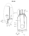
- finishing surface 40 of the cover 300 is screw-engaged with the outer cylinder 200 as shown in FIG. 20 , and the sealing member 420 is in contact with the edge of the exterior of the outer cylinder 200.
- the cover 300 includes a shielding plate 310 for sealing up one open side of the inner cylinder 100, and a contact groove 320 formed between the shielding plate 310 and the finishing surface 410 along the edge of the shielding plate 310 to face the edge of the interior of the inner cylinder 100.
- the contact groove 320 is formed for the purpose of reinforcement that properly disperses the load and stress due to the temperature control member 301 and the thermostat 302 mounted on the cover 300.
- finishing surface 410 is screw-engaged with the end side outer surface of the outer cylinder 200, and the sealing member 420 is interposed between the contact groove 320 and the finishing surface 410 to be in close contact with the edge of the inner cylinder 100 and the edge outer side of the outer cylinder 200, so that the sealing becomes possible.
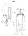
- the finishing surface of the cover 300 is screw-engaged with the inner cylinder 100, and the sealing member becomes in contact with the inner side of the inner cylinder 100. This structure will be described with reference to FIGS. 21 and 22 .
- the cover 300 may be prepared in the form that includes a shielding plate 310 that seals up one open side of the inner cylinder 100 as shown in FIG. 21 , a contact groove 330 formed between the shielding plate 310 and the finishing surface 430 along the edge of the shielding plate 310 to face the edge of the inner side of the inner cylinder 100, and a finishing sleeve 340 extending to be bent from the end portion of the finishing surface 430, having a sealing member 440 mounted thereon, and surrounding the edges of the outer cylinder 200 and the inner cylinder 100.
- the contact groove 330 is formed for the purpose of reinforcement that properly disperses the load and stress due to the temperature control member 301 and the thermostat 302 mounted on the cover 300, and the finishing sleeve 340 is prepared to provide a space in which the sealing member 440 is installed.
- the finishing surface 430 extends from the edge of the contact groove 330 and is mutually screw-engaged with the end side inner surface of the inner cylinder 100
- the sealing member 440 has one side that is in close contact with the edges of the inner cylinder 100 and the outer cylinder 200, and the other side that is in close contact with the edge inner side of the inner cylinder 100, so that the sealing becomes possible.
- the cover 300 may be prepared in the form that includes a shielding plate 310 that seals up one open side of the inner cylinder 100 as shown in FIG. 22 , and a finishing sleeve 350 extending to be bent from the end portion of the finishing surface, having a sealing member 460 mounted thereon, and surrounding the edges of the outer cylinder 200 and the inner cylinder 100.
- the finishing sleeve 350 is prepared to provide a space in which the sealing member 460 is installed.
- the finishing surface 450 is mutually screw-engaged to face the end side inner surface of the inner cylinder 100
- the sealing member 460 has one side that is in close contact with the edges of the inner cylinder 100 and the outer cylinder 200, and the other side that is in close contact with the edge inner side of the inner cylinder 100, so that the sealing becomes possible.
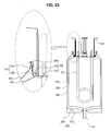
- the cover 300 may be prepared in the form that includes a shielding plate 310 that seals up one open side of the inner cylinder 100 as shown in FIG. 23 , a finishing sleeve 360 extending to be bent from the end portion of the finishing surface 450 and surrounding the edges of the outer cylinder 200 and the inner cylinder 100, and an engagement valley 370 formed along the outer surface of the finishing surface 470 and having a ring-shaped sealing member 480 mounted thereon.
- the finishing sleeve 360 is prepared to protect a welded region in which the edges of the inner cylinder 100 and the outer cylinder 200 are welded in a body from external physical and chemical impacts.
- the engagement valley 370 is prepared to provide a space in which the sealing member 480 is installed.
- finishing surface 470 is mutually screw-engaged to face the end side inner surface of the inner cylinder 100, and the sealing member 460 is mounted on the engagement valley 370 to be in close contact with the end side inner surface of the inner cylinder 100, so that the sealing becomes possible.
- the cover 300 may be prepared in the form that includes a shielding plate 310 that seals up one open side of the inner cylinder 100 as shown in FIG. 24 , a finishing sleeve 360 extending to be bent from the end portion of the finishing surface 470 and surrounding the edges of the outer cylinder 200 and the inner cylinder 100, and an engagement valley 370 formed along the outer surface of the finishing surface 470.
- the finishing sleeve 360 and the engagement valley 370 are prepared to provide a space in which the sealing member 480 is installed.
- finishing surface 470 is mutually screw-engaged with the end side inner surface of the inner cylinder 100, and the sealing member 440 is in close contact with the edges of the inner cylinder 100 and the outer cylinder 200, and is in close contact with the end side inner surface of the inner cylinder 100, so that the sealing becomes possible.
- the sealing member 480 may adopts a structure that includes a first sealing member 482 mounted on the finishing sleeve 360 and having one side that is in close contact with the edges of the inner cylinder 100 and the outer cylinder 200 and the other side that is in close contact with the edge inner side of the inner cylinder 100, and a ring-shaped second sealing member 484 mounted on the engagement valley 370 to be in close contact with the end side inner surface of the inner cylinder 100.
- the present invention may adopt a structure in which a sealing member 490' is interposed between the edges of the inner cylinder 100 and the outer cylinder 200 and the finishing surface 490.
- the cover 300 may be prepared in the form that includes a shielding plate 310 that seals up one open side of the inner cylinder 100 and a contact groove 380 formed between the shielding plate 310 and the finishing surface 490 along the edge of the shielding plate 310 to face the edge of the inner side of the inner cylinder 100.
- finishing sleeve 490 extends in parallel to the shielding plate 310 from the edge of the contact groove 380, and the sealing member 490' extends from the edges of the inner cylinder 100 and the outer cylinder 200 bonded in welding in a body and is in close contact between the finishing surface 490 and the bent surface 490" facing the finishing surface 490, so that the sealing becomes possible.
- the seal ring block 600 briefly includes a first ring block 610 and a second ring block 620.
- the first ring block 610 is in a ring shape as a whole, and has a structure in which a ring protrusion 612 having a shape corresponding to the contact groove 380 is prepared and a finishing groove 614 extending from the ring protrusion 612 and accommodating the finishing surface 490.
- the second ring block 620 is in a ring shape as a whole, and has a structure in which a stepped portion 622 for safe placement of the bent surface thereon is prepared and is engaged with the first ring block 610.
- first ring block 610 and the second ring block 620 are penetratingly engaged with each other by a plurality of fixing bolts 630 mounted apart from one another.
- a vacuum retaining portion 500 for discharging remaining air between the inner cylinder 100 and the outer cylinder 200 is further included.
- the vacuum retaining portion 500 is necessary to make the space 900 in a vacuum state after the edges of the inner cylinder 100 and the outer cylinder 200 are welded in a body, and is further necessary for the later maintenance and inspection.
- the vacuum retaining portion 500 includes an air discharge tube 510 provided on one side of the outer cylinder 200, and a protection cover 520 engaged with one side of the outer cylinder 200 to protect the air discharge tube 510.
- the present invention may be applicable by an embodiment in which a pressure member is formed on the outer surface of the outer cylinder 200, and the sealing portion 400 is formed by a curling process, welding, or filler P.
- the pressure member that is formed on the outer surface of the outer cylinder 200 keeps the balance of pressure on the inner and outer sides of the space portion 900 and keeps the shape of the inner cylinder 100 and the outer cylinder 200 when the remaining air is discharged through the air discharge tube 510 as illustrated.
- the pressure member is to keep the balance of pressure on the inner and outer sides of the space portion 900 and to keep the shape of the inner and outer cylinders 100 and 200, and includes a first protrusion ring 210 and a second protrusion ring 534.
- the pressure member is provided to improve the entire structural strength of the water tank in addition to the purpose of preventing the inner and outer cylinders 100 and 200 from being deformed due to the pressure unbalance on the inner and outer sides of the space portion 900 in the process of discharging the remaining air to keep the vacuum state of the space portion 900 through the vacuum retaining portion 500 to be described later.
- the first protrusion ring 210 projects from the outer surface of the outer cylinder 200 in a ring shape along at least one outer periphery in upward and downward directions.
- the second protrusion ring 210 is provided on a bottom surface 530 of the outer cylinder 200 through which a drain tube 101 that communicates with the center of the bottom surface of the inner cylinder 100 passes.
- At least one second protrusion ring 210 projects in the form of a concentric circle around the drain tube 101.
- the first and second protrusion rings 210 and 534 are provided on the outer periphery and the bottom surface of the outer cylinder 200, respectively, which are caused by the fact that a panel of which the actual area has been increased due to its projecting or wrinkled structure has a structural strength that is higher than that of a smooth and flat panel that does not have the projecting or wrinkled structure.
- the cover 300 finishes the body 10 as described above.
- a valley 307 that is recessed in the body 10 is formed in a ring shape along the edge, and the sealing portion 400 extends from the edge of the valley 307 and firmly keeps the sealing state in a method such as curling process, filling of packing material P, welding, and the like after the valley 307 is fit-engaged with the edge of the body 10.
- the valley 307 is firmly fastened in the initial process of making the cover 300 engaged with the body 10, and efficiently disperses and supports the load of the respective members mounted on the cover such as the pressure member and so on, and improves the structural strength.
- the valley 307 includes one side wall 307', a bottom 307", and the other side wall 307"'.
- the one side wall 307' extends from the edge of the cover 300, and bent to the interior of the body 10 at right angles to the cover 300.
- the bottom 307" extends from the end portion of the one side wall 307' and is bent in parallel to the cover.
- the other side wall 307"' extends from the bottom 307" and is bent in parallel to the one side wall 307'.
- the sealing portion 400 to be described later extends from the edge of the other side wall 307"' and an outer surface of the other side wall 307"' becomes in contact with the inner surface of the inner cylinder 100.
- a steam bent tube 308 penetrates the cover 300, and the steam bent tube 308 is provided to compulsorily discharge steam to the upper side in order to prevent the steam, which is generated when the water is heated in the case where the body 10 is used as a hot water tank, from flowing into the water outlet tube or flowing backward.
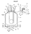
- the sealing portion 400 is provided to keep the sealing state between the body 100 and the cover 300, and as shown in FIG. 27 , includes a fifth bent portion 45, a sixth bent portion 65, and a welding engagement portion W and a packing material P.
- the fifth bent portion 45 is a portion prepared by bending the engagement surface, which is obtained by bonding the edge of the open side of the inner cylinder 100 and the edge of the open side of the outer cylinder 200, toward the outer side of the outer cylinder 200 in the form of a flange.
- the sixth bent portion 65 is a portion which extends from the edge of the cover, i.e. the edge of the other side wall 307"' of the valley 307, surrounds the upper and lower portions of the engagement surface in a " ⁇ " or " ⁇ "-shaped, and thus is kept in an actual sealing state.
- the welding engagement portion W is a portion prepared by performing welding along the region that is in contact with the end portion of the fifth bent portion 45, i.e. the end portions of the inner cylinder 100 and the outer cylinder 200, and prevents external air from flowing into the space portion 900.
- the packing material P fills between the upper surface of the engagement surface and the sixth bent portion 65, and typically is silicon and so on. More specifically, if the silicon spread in a direction of forming the sixth bent portion 65 and the engagement surface is solidified, the cover 300 and the body 10 are mutually engaged with each other, and the sixth bent portion 65 is formed through a method such as a curling process and so on.
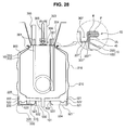
- the sealing portion 400 may be applicable by an embodiment of the present invention, in which a separate reinforcement piece 55 is engaged with the first engagement portion 46 as shown in FIG. 28 , welding and filling of the packing material P is performed, and then the sixth bent portion 65 is formed.
- the first engagement portion 46 is a portion that is formed by the engagement surface in which the edge on the open side of the inner cylinder 100 and the edge on the open side of the outer cylinder 200 are engaged with each other.
- the reinforcement piece 55 and the welding engagement portion W are formed in the first engagement portion 46.
- the reinforcement piece 55 is in the form of a ring that is engaged along the edge of the exterior of the engagement surface, and it is preferable that is made of a material of the same series as that of the inner cylinder 100 and the outer cylinder 200.
- the welding engagement portion W is a portion prepared by performing welding in the form of a ring along the regions where the first engagement portion 46 and the reinforcement piece 55 are in contact with each other.
- the welding engagement portion W is formed to intercept the inflow of external air into the space portion 900 in the direction of forming the first engagement portion 46 and to make the engagement of the reinforcement piece 55 that provides a space in which the sixth bent portion 65 is formed.
- the sixth bent portion 65 extends from the edge of the cover 300 that is in contact with the inner side surface of the engagement surface, i.e. from the edge of the other side wall 307"' of the valley 307, and surrounds the end portion of the engagement surface and the upper and lower portions of the reinforcement piece 55.
- the packing material P fills between the upper portion of the reinforcement piece 55 and the second bent portion 65.
- the upper surface of the second bent portion 65 as illustrated in FIG. 27 (see imaginary line of dotted portion extending from the upper surface of the cover 300) and FIG. 28 is formed to be equal to or lower than the upper surface of the cover 300 on which electric devices such as a temperature sensor 306 or the like is mounted so that the electronic devices mounted on the upper surface of the cover 330 do not touch the water even if the water leaks through the valley 307.
- the sealing portion 400 may be formed by making the reinforcement piece 55 engaged with the first engagement portion 46 as shown in FIG. 29 and performing welding of the reinforcement piece 55 and the edge of the cover 300.
- the first engagement portion 46 is a portion formed by the engagement surface that is obtained by mutually contacting the edge of the open side of the inner cylinder with the edge of the open side of the outer cylinder 200.
- the reinforcement piece 55 and the welding engagement portion W to be described later are formed on the first engagement portion 46.
- the reinforcement piece 55 is in the form of a ring that is engaged along the edge on the outer side of the engagement surface, and it is preferable that the reinforcement piece 55 is made of a material of the same series as that of the inner cylinder 100 and the outer cylinder 200 so that the welding can be performed.
- the second engagement portion 66 is a portion that is formed through the surface contact between the edge of the cover 300 and the reinforcement piece 55.
- the first welding engagement portion W1 is prepared by performing welding in the form of ring along the region where the first engagement portion 46 and the reinforcement piece 55 contact each other, and the second welding engagement portion W2 is prepared by performing welding in the form of a ring along the end portions of the first engagement portion 46 and the second engagement portion 65.
- the first welding engagement portion W1 is formed to intercept the inflow of an external air into the space portion 900 and to make the engagement of the reinforcement piece 55 that provides a space in which a sixth bent portion 65 to be described later is formed.
- the second welding engagement portion W2 is formed to keep the sealing state by finally sealing the body 10 and the cover 300.
- a structure for forming a reinforcement ring protrusion 308 that protrudes along the edge on the inner side of the reinforcement piece 55 on which the second engagement portion 66 is formed may be provided, and the reinforcement ring protrusion 308 is prepared for the purpose of improving the structural strength such as the valley 307.
- the space portion 900 is required to be kept nearly in vacuum state.
- the vacuum retaining portion 500 is prepared for this.
- the protection cover 520 is configured to have a following structure, in which the remaining air in the space portion 900 is discharged through an air discharge tube 510, the air discharge tube 510 is sealed by a separate finishing member (not illustrated), and then the air discharge tube 510 is surrounded by the protection cover 520.
- the protection cover 520 may be configured to include a cylindrical wall 521 that is detachably engaged with the outer surface on the lower portion of the outer cylinder 200, a bottom surface 521' which extends from the edge of the lower end portion of the cylindrical wall 521 to a drain tube 101 communicating with the center of the bottom surface of the inner cylinder 100 and the center of which is penetrated, and a contact horn 523 which extends from the edge of the penetrated center of the bottom surface 521' to a bottom surface 530 of the outer cylinder 200 and which is in close contact with the bottom surface 530 of the outer cylinder 200.
- the protection cover 520 has a detachable structure which can be detached when it is required to discharge the remaining air in the space portion 900 through the air discharge tube 510 using a vacuum pump or the like in the case where the vacuum state of the space portion 900 becomes weak due to its long-time use.
- the edge of the end portion of the contact horn 523 is fixed in close contact with a contact ring protrusion 532 that projects in the form of a ring around the drain tube 101 from the bottom surface 530 of the outer cylinder 200.
- the protection cover 520 is detachably engaged with a stepped engagement surface 220 having a stepped portion along the outer surface on the lower portion of the outer cylinder 200.
- the unexplained reference numeral "230" denotes a finishing sleeve that is prepared to make the bottom surface 530 of the outer cylinder 200, on which a second protrusion ring 534 is formed, engaged with the outer periphery of the outer cylinder 200.
- a first locking ring groove 522 that is recessed along the outer periphery toward the stepped engagement surface 220 is provided, and on the stepped engagement surface 220, a second locking ring groove 222 that is recessed toward the inner cylinder 100 in a position corresponding to the first locking ring groove 522 is provided, so that the first and second locking ring grooves 522 and 222 are engaged to provide a sealing structure.
- the water tank having a sealing element according to the present invention facilitates the cleaning of the interior of the water tank and achieves an accurate sealing. Also, the water tank according to the present invention minimizes the energy consumption for heating or cooling water in the water tank through heightening of the heat insulation performance.
Landscapes
- Engineering & Computer Science (AREA)
- Physics & Mathematics (AREA)
- Thermal Sciences (AREA)
- Chemical & Material Sciences (AREA)
- Combustion & Propulsion (AREA)
- Mechanical Engineering (AREA)
- General Engineering & Computer Science (AREA)
- Closures For Containers (AREA)
- Gasket Seals (AREA)
- Devices That Are Associated With Refrigeration Equipment (AREA)
- Heat-Exchange Devices With Radiators And Conduit Assemblies (AREA)
- Heat-Pump Type And Storage Water Heaters (AREA)
Applications Claiming Priority (3)
| Application Number | Priority Date | Filing Date | Title |
|---|---|---|---|
| KR1020090080778A KR20110023145A (ko) | 2009-08-28 | 2009-08-28 | 냉온수기용 온수조 |
| KR1020100030517A KR20110111114A (ko) | 2010-04-02 | 2010-04-02 | 진공단열 수조 |
| KR20100071065 | 2010-07-22 |
Publications (1)
| Publication Number | Publication Date |
|---|---|
| EP2295887A2 true EP2295887A2 (fr) | 2011-03-16 |
Family
ID=43127362
Family Applications (1)
| Application Number | Title | Priority Date | Filing Date |
|---|---|---|---|
| EP10008744A Withdrawn EP2295887A2 (fr) | 2009-08-28 | 2010-08-23 | Réservoir d'eau avec élément d'étanchéité |
Country Status (4)
| Country | Link |
|---|---|
| US (1) | US20110049148A1 (fr) |
| EP (1) | EP2295887A2 (fr) |
| JP (1) | JP2011064449A (fr) |
| CN (1) | CN102001478A (fr) |
Cited By (2)
| Publication number | Priority date | Publication date | Assignee | Title |
|---|---|---|---|---|
| EP2770268A1 (fr) * | 2013-02-22 | 2014-08-27 | Wolf GmbH | Boîtier destiné à recevoir au moins un élément de chauffage et système de boîtier |
| US12013169B2 (en) | 2015-05-20 | 2024-06-18 | Lg Electronics Inc. | Refrigerator |
Families Citing this family (15)
| Publication number | Priority date | Publication date | Assignee | Title |
|---|---|---|---|---|
| KR101291876B1 (ko) * | 2011-07-08 | 2013-07-31 | 엘지전자 주식회사 | 정수기 |
| JP5767927B2 (ja) * | 2011-09-25 | 2015-08-26 | 株式会社ユタカ技研 | 熱交換器 |
| KR101497080B1 (ko) * | 2013-02-01 | 2015-03-03 | 김수복 | 진공 단열 온수통 및 그 제조방법 |
| CN103990560B (zh) * | 2013-02-20 | 2018-01-05 | 珠海格力电器股份有限公司 | 一种水粒子发生器及具有其的空调器 |
| US10085584B2 (en) * | 2014-06-09 | 2018-10-02 | Whirlpool Corporation | Method of regulating temperature for sous vide cooking and apparatus therefor |
| CN104590711A (zh) * | 2014-12-30 | 2015-05-06 | 孙冰 | 一种可以制作“疙瘩”的食品罐及其制作“疙瘩”的方法 |
| KR101738294B1 (ko) * | 2016-01-04 | 2017-05-19 | 엘지전자 주식회사 | 냉장고 |
| KR102413211B1 (ko) * | 2017-09-05 | 2022-06-27 | 현대자동차주식회사 | 차량의 냉각수 가열장치 |
| CN108302759A (zh) * | 2017-12-19 | 2018-07-20 | 无锡其宏包装材料厂 | 一种蒸汽加热水箱 |
| CN109092217B (zh) * | 2018-09-10 | 2020-06-02 | 江苏民生重工有限公司 | 一种化工生产用气相超稳反应器 |
| CN109595793A (zh) * | 2018-09-26 | 2019-04-09 | 中山市恒乐电器有限公司 | 一种带可分离式热交换器的燃气热水器 |
| CN109458729B (zh) * | 2018-11-01 | 2025-06-03 | 佛山市海德精工电子科技有限公司 | 管式厚膜加热器保护装置及管式厚膜加热器 |
| CN111998529B (zh) * | 2019-05-27 | 2024-09-20 | 艾欧史密斯(中国)热水器有限公司 | 储水容器、电热水器以及热水器水箱的制造方法 |
| CN113415532B (zh) * | 2021-05-26 | 2024-11-05 | 中冶焦耐(大连)工程技术有限公司 | 一种负压水封槽 |
| AU2023278818A1 (en) * | 2022-06-02 | 2024-12-19 | Rheem Manufacturing Company | Embossed heads for tanks and tanks including same |
Family Cites Families (8)
| Publication number | Priority date | Publication date | Assignee | Title |
|---|---|---|---|---|
| JPH11245929A (ja) * | 1998-03-04 | 1999-09-14 | Inax Corp | 樹脂製タンク及び吐水設備 |
| KR100334941B1 (ko) * | 1999-07-01 | 2002-05-04 | 최상필 | 냉, 온수기의 온수조 |
| KR100334940B1 (ko) * | 1999-09-16 | 2002-05-04 | 최상필 | 냉온수기의 분리가능한 온수조 |
| JP2001300666A (ja) * | 2000-04-19 | 2001-10-30 | Sango Co Ltd | 缶の製造方法 |
| JP3951224B2 (ja) * | 2002-04-11 | 2007-08-01 | 株式会社Inax | 温水タンク |
| KR100834079B1 (ko) * | 2004-07-30 | 2008-06-09 | 최상필 | 냉온정수기용 온수조의 온도조절수단고정구 |
| KR100619159B1 (ko) * | 2004-08-27 | 2006-09-04 | 최상필 | 온수역류가 방지되는 냉온정수기용 온수조 |
| CN2830320Y (zh) * | 2005-10-13 | 2006-10-25 | 张伟平 | 带温度计的水箱盖 |
-
2010
- 2010-08-23 EP EP10008744A patent/EP2295887A2/fr not_active Withdrawn
- 2010-08-23 JP JP2010185800A patent/JP2011064449A/ja active Pending
- 2010-08-25 US US12/862,834 patent/US20110049148A1/en not_active Abandoned
- 2010-08-25 CN CN2010102634840A patent/CN102001478A/zh active Pending
Non-Patent Citations (1)
| Title |
|---|
| None |
Cited By (3)
| Publication number | Priority date | Publication date | Assignee | Title |
|---|---|---|---|---|
| EP2770268A1 (fr) * | 2013-02-22 | 2014-08-27 | Wolf GmbH | Boîtier destiné à recevoir au moins un élément de chauffage et système de boîtier |
| US12013169B2 (en) | 2015-05-20 | 2024-06-18 | Lg Electronics Inc. | Refrigerator |
| EP3628949B1 (fr) * | 2015-05-20 | 2024-10-23 | LG Electronics Inc. | Réfrigérateur |
Also Published As
| Publication number | Publication date |
|---|---|
| CN102001478A (zh) | 2011-04-06 |
| JP2011064449A (ja) | 2011-03-31 |
| US20110049148A1 (en) | 2011-03-03 |
Similar Documents
| Publication | Publication Date | Title |
|---|---|---|
| EP2295887A2 (fr) | Réservoir d'eau avec élément d'étanchéité | |
| US20090260583A1 (en) | Separable hot water tank | |
| CN1318813C (zh) | 绝热壁 | |
| JP2009229027A (ja) | 貯湯タンクユニット及びそれを用いたヒートポンプ給湯機 | |
| KR20110111114A (ko) | 진공단열 수조 | |
| KR20110096214A (ko) | 전기식 온수탱크 | |
| KR101221476B1 (ko) | 단열공간을 구비한 이중 탱크 | |
| KR101184371B1 (ko) | 냉온수기 | |
| KR20120010075A (ko) | 진공단열 수조 | |
| KR101247151B1 (ko) | 단열 온수조 | |
| CN204429621U (zh) | 一种点胶设备的胶桶装置 | |
| KR20100105173A (ko) | 단열 온수조 | |
| JPH11197020A (ja) | 電気貯湯容器 | |
| JP6500207B2 (ja) | 貯湯タンクユニットおよびそれを備えた給湯装置 | |
| JP2008541923A (ja) | 洗濯機のヒーター装置 | |
| JP5266781B2 (ja) | 断熱容器 | |
| JP6324826B2 (ja) | 貯湯タンクユニット | |
| JPWO2016001956A1 (ja) | 貯湯タンクユニット、貯湯式給湯機、および、貯湯ユニットへの代替温度センサの設置方法 | |
| JP6301221B2 (ja) | 貯湯タンクユニット | |
| JP4715885B2 (ja) | 断熱機器 | |
| KR200446236Y1 (ko) | 냉온수기용 온수조 | |
| JP6314045B2 (ja) | 貯湯タンクユニット | |
| KR20100113432A (ko) | 단열 온수조 | |
| JP5359347B2 (ja) | 炊飯器 | |
| JP2006349321A (ja) | 貯湯タンク |
Legal Events
| Date | Code | Title | Description |
|---|---|---|---|
| PUAI | Public reference made under article 153(3) epc to a published international application that has entered the european phase |
Free format text: ORIGINAL CODE: 0009012 |
|
| AK | Designated contracting states |
Kind code of ref document: A2 Designated state(s): AL AT BE BG CH CY CZ DE DK EE ES FI FR GB GR HR HU IE IS IT LI LT LU LV MC MK MT NL NO PL PT RO SE SI SK SM TR |
|
| AX | Request for extension of the european patent |
Extension state: BA ME RS |
|
| STAA | Information on the status of an ep patent application or granted ep patent |
Free format text: STATUS: THE APPLICATION IS DEEMED TO BE WITHDRAWN |
|
| 18D | Application deemed to be withdrawn |
Effective date: 20130301 |