EP2298164A2 - Vorrichtung zur Kardiale Überwachung mit Adaptive Probenentnahme - Google Patents
Vorrichtung zur Kardiale Überwachung mit Adaptive Probenentnahme Download PDFInfo
- Publication number
- EP2298164A2 EP2298164A2 EP10176687A EP10176687A EP2298164A2 EP 2298164 A2 EP2298164 A2 EP 2298164A2 EP 10176687 A EP10176687 A EP 10176687A EP 10176687 A EP10176687 A EP 10176687A EP 2298164 A2 EP2298164 A2 EP 2298164A2
- Authority
- EP
- European Patent Office
- Prior art keywords
- signal
- impedance
- ecg
- power
- integrated circuit
- Prior art date
- Legal status (The legal status is an assumption and is not a legal conclusion. Google has not performed a legal analysis and makes no representation as to the accuracy of the status listed.)
- Granted
Links
Images










Classifications
-
- A—HUMAN NECESSITIES
- A61—MEDICAL OR VETERINARY SCIENCE; HYGIENE
- A61B—DIAGNOSIS; SURGERY; IDENTIFICATION
- A61B5/00—Measuring for diagnostic purposes; Identification of persons
- A61B5/72—Signal processing specially adapted for physiological signals or for diagnostic purposes
- A61B5/7225—Details of analogue processing, e.g. isolation amplifier, gain or sensitivity adjustment, filtering, baseline or drift compensation
-
- A—HUMAN NECESSITIES
- A61—MEDICAL OR VETERINARY SCIENCE; HYGIENE
- A61B—DIAGNOSIS; SURGERY; IDENTIFICATION
- A61B5/00—Measuring for diagnostic purposes; Identification of persons
- A61B5/05—Detecting, measuring or recording for diagnosis by means of electric currents or magnetic fields; Measuring using microwaves or radio waves
- A61B5/053—Measuring electrical impedance or conductance of a portion of the body
- A61B5/0531—Measuring skin impedance
-
- A—HUMAN NECESSITIES
- A61—MEDICAL OR VETERINARY SCIENCE; HYGIENE
- A61B—DIAGNOSIS; SURGERY; IDENTIFICATION
- A61B5/00—Measuring for diagnostic purposes; Identification of persons
- A61B5/24—Detecting, measuring or recording bioelectric or biomagnetic signals of the body or parts thereof
- A61B5/30—Input circuits therefor
- A61B5/305—Common mode rejection
-
- A—HUMAN NECESSITIES
- A61—MEDICAL OR VETERINARY SCIENCE; HYGIENE
- A61B—DIAGNOSIS; SURGERY; IDENTIFICATION
- A61B5/00—Measuring for diagnostic purposes; Identification of persons
- A61B5/24—Detecting, measuring or recording bioelectric or biomagnetic signals of the body or parts thereof
- A61B5/30—Input circuits therefor
- A61B5/307—Input circuits therefor specially adapted for particular uses
- A61B5/308—Input circuits therefor specially adapted for particular uses for electrocardiography [ECG]
-
- A—HUMAN NECESSITIES
- A61—MEDICAL OR VETERINARY SCIENCE; HYGIENE
- A61B—DIAGNOSIS; SURGERY; IDENTIFICATION
- A61B5/00—Measuring for diagnostic purposes; Identification of persons
- A61B5/24—Detecting, measuring or recording bioelectric or biomagnetic signals of the body or parts thereof
- A61B5/316—Modalities, i.e. specific diagnostic methods
- A61B5/318—Heart-related electrical modalities, e.g. electrocardiography [ECG]
- A61B5/33—Heart-related electrical modalities, e.g. electrocardiography [ECG] specially adapted for cooperation with other devices
-
- A—HUMAN NECESSITIES
- A61—MEDICAL OR VETERINARY SCIENCE; HYGIENE
- A61B—DIAGNOSIS; SURGERY; IDENTIFICATION
- A61B5/00—Measuring for diagnostic purposes; Identification of persons
- A61B5/24—Detecting, measuring or recording bioelectric or biomagnetic signals of the body or parts thereof
- A61B5/316—Modalities, i.e. specific diagnostic methods
- A61B5/318—Heart-related electrical modalities, e.g. electrocardiography [ECG]
- A61B5/346—Analysis of electrocardiograms
-
- A—HUMAN NECESSITIES
- A61—MEDICAL OR VETERINARY SCIENCE; HYGIENE
- A61B—DIAGNOSIS; SURGERY; IDENTIFICATION
- A61B5/00—Measuring for diagnostic purposes; Identification of persons
- A61B5/72—Signal processing specially adapted for physiological signals or for diagnostic purposes
- A61B5/7203—Signal processing specially adapted for physiological signals or for diagnostic purposes for noise prevention, reduction or removal
- A61B5/7207—Signal processing specially adapted for physiological signals or for diagnostic purposes for noise prevention, reduction or removal of noise induced by motion artifacts
-
- A—HUMAN NECESSITIES
- A61—MEDICAL OR VETERINARY SCIENCE; HYGIENE
- A61B—DIAGNOSIS; SURGERY; IDENTIFICATION
- A61B5/00—Measuring for diagnostic purposes; Identification of persons
- A61B5/72—Signal processing specially adapted for physiological signals or for diagnostic purposes
- A61B5/7221—Determining signal validity, reliability or quality
-
- A—HUMAN NECESSITIES
- A61—MEDICAL OR VETERINARY SCIENCE; HYGIENE
- A61B—DIAGNOSIS; SURGERY; IDENTIFICATION
- A61B5/00—Measuring for diagnostic purposes; Identification of persons
- A61B5/72—Signal processing specially adapted for physiological signals or for diagnostic purposes
- A61B5/7228—Signal modulation applied to the input signal sent to patient or subject; Demodulation to recover the physiological signal
-
- A—HUMAN NECESSITIES
- A61—MEDICAL OR VETERINARY SCIENCE; HYGIENE
- A61B—DIAGNOSIS; SURGERY; IDENTIFICATION
- A61B5/00—Measuring for diagnostic purposes; Identification of persons
- A61B5/72—Signal processing specially adapted for physiological signals or for diagnostic purposes
- A61B5/7232—Signal processing specially adapted for physiological signals or for diagnostic purposes involving compression of the physiological signal, e.g. to extend the signal recording period
-
- A—HUMAN NECESSITIES
- A61—MEDICAL OR VETERINARY SCIENCE; HYGIENE
- A61B—DIAGNOSIS; SURGERY; IDENTIFICATION
- A61B5/00—Measuring for diagnostic purposes; Identification of persons
- A61B5/72—Signal processing specially adapted for physiological signals or for diagnostic purposes
- A61B5/7235—Details of waveform analysis
- A61B5/7239—Details of waveform analysis using differentiation including higher order derivatives
-
- G—PHYSICS
- G01—MEASURING; TESTING
- G01R—MEASURING ELECTRIC VARIABLES; MEASURING MAGNETIC VARIABLES
- G01R19/00—Arrangements for measuring currents or voltages or for indicating presence or sign thereof
- G01R19/25—Arrangements for measuring currents or voltages or for indicating presence or sign thereof using digital measurement techniques
- G01R19/2506—Arrangements for conditioning or analysing measured signals, e.g. for indicating peak values ; Details concerning sampling, digitizing or waveform capturing
- G01R19/2509—Details concerning sampling, digitizing or waveform capturing
Definitions
- the present invention relates to analogue signal processors and is more particularly, although not exclusively concerned with the analogue signal processors that can be used for the monitoring of biopotential signals.
- Continua Health Alliance www.continuaalliance.org .
- Continua Health Alliance members have created an ecosystem of connected personal health technologies, devices, and services that enable a more efficient exchange of health and wellness information.
- Many leading global technology companies and healthcare organizations have embraced this ecosystem, and following a set of interoperability guidelines, different products are able to exchange health information seamlessly.
- Intelesens Limited manufacture and provide a variety of wireless sensors that can be used for the remote monitoring of vital signs in a patient as described on their website, www.intelesens.com .
- a versatile wireless monitoring technology is provided which can be used for either short range or long range, using cellular communications networks, monitoring of a variety of vital sign inputs.
- the sensors are very small and light weight with an extremely long battery life, and because of their size, can be small, unobtrusive and easily worn under clothes allowing patients freedom during monitoring.
- Wireless cardiovascular systems are also available, such as, Piix and zLink (trademarks of Corventis Inc), that monitor a patient's cardiovascular system, downloads the information and transmits it to Corventis Inc. for evaluation (www.corventis.com).
- US-A-2008/0269631 discloses a seizure prediction system that includes measuring impedance within a brain of a patient to determine whether the patient is likely to have a seizure. On detecting a state in which seizure is likely to occur, therapy delivery may be activated for the patient being monitored.
- an application-specific integrated circuit for cardiac monitoring comprising:- an electrocardiogram readout channel having an input and an output, the input being arranged to receive a monitored signal and the output providing a electrocardiogram signal; and an adaptive sampling unit for sampling the electrocardiogram signal; characterised in that the adaptive sampling unit includes an adaptive threshold generation unit that generates a threshold value used to control the adaptive sampling unit.
- the adaptive sampling unit further comprises an activity detector that includes the adaptive threshold generation unit.
- the application-specific integrated circuit may further comprise a band-power extraction channel that extracts power information from the monitored signal as well as an impedance readout channel that extracts impedance information from the monitored signal.
- a stimulation current generator may also be provided for a device of which the circuit forms a part.
- the stimulation current generator preferably comprises chopper stabilised AC sources.
- the application-specific integrated circuit also includes at least one input stage for providing the monitored signal to at least the electrocardiogram channel. Ideally, one input stage is provided for both the electrocardiogram channel and the band-power extraction channel. An additional input stage is provided for the impedance readout channel.
- the application-specific integrated circuit further comprises at least one output stage, one for the electrocardiogram channel, two for the band-power extraction channel and two for the impedance readout channel - one for each of the imaginary and real components output by each of the band-power extraction channel and the impedance readout channel.
- both the input and output stages comprise instrumentation amplifiers.
- two low frequency oscillators and one high frequency oscillator is provided, together with a bias circuit generator, configuration registers and a digital control circuit.
- the adaptive sampling unit comprises an analogue-to-digital converter so that only electrocardiogram signals are sampled at a high frequency and digitised for further processing.
- a medical monitoring device comprising:- an application-specific integrated circuit as described above; a digital controller for processing signals output by the application-specific integrated circuit and for providing control signals to the application-specific integrated circuit; and a wireless module for receiving data from the digital controller and for transmitting it to a network.
- a wireless electrocardiogram monitoring system comprising:- a network; and a medical monitoring device as described above, the wireless module of the medical monitoring device transmitting data to the network.
- a method for operating a medical monitoring device comprising the steps of:- determining a change in an impedance measurement in an electrocardiogram signal with respect to a predetermined threshold value; and activating processing activities of the device.
- the processing activities of the device are activated when the impedance measurement falls below the predetermined threshold value, and are deactivated when the impedance measurement rises above the predetermined threshold value.
- a method for transferring data from a medical monitoring device as described above comprising the steps of:- determining an adaptively sampled ECG signal; processing the adaptively sampled ECG signal to extract features therefrom; and transmitting data relating to the extracted features to a host network.
- the data may be transferred continuously, or transferred when a disorder is detected in the extracted features. In either case, the data may also be stored within the medical monitoring device.
- a method for simultaneously retrieving data from a medical monitoring device described above comprising the steps of:- deriving an electrocardiogram signal; and deriving at least band-power measurements from the derived electrocardiogram signal.
- the derived band-power measurements may be used for beat detection. In this case, a low-power beat detection algorithm is used.
- the method further comprises the step of deriving impedance measurements from the derived electrocardiogram signal.
- the derived impedance measurements may be used to remove artefacts from the derived electrocardiogram signal to provide a compensated electrocardiogram signal that can be used for beat detection.
- the derived impedance measurements may also be used for detecting the presence of artefacts. If no artefacts are detected, the derived band-power measurements may be used for beat detection. If artefacts are detected, the derived electrocardiogram signal may be used for beat detection. In this case, a precision beat detection algorithm is used.
- RR intervals the distance between peaks in an electrocardiogram signal, may be determined from the derived impedance measurements. If the RR intervals are not consistent, the electrocardiogram signal is used for beat detection instead of the band-power measurements.
- the ASP ASIC extracts ECG signals with high signal quality, assists DSP platforms for low-power signal analysis and data compression, and monitors the signal integrity of the ECG signal extraction whilst enabling a significant reduction in power consumption of the system.
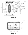
- a 'connected healthcare' system 100 that provides a vision for future healthcare systems utilising miniature and smart sensor nodes for extracting key medical information.
- the power dissipation of these sensor nodes is dominated by digital signal processing and wireless data transmission.
- a patient 110 wears a monitor 120 that can monitor vital signs, for example, electroencephalogram (EEG) signals, vision, hearing, ECG signals, blood pressure, glucose levels, DNA protein, positioning, toxins and implants.
- the monitor 120 communicates with a network 130 transmitting signals relating to the patient's vital signs.
- the network may be connected by a standard telephone landline 140, by cellular telephone 150 or by a wireless local area network (WLAN) 160.
- the network 130 monitors the signals and interacts with doctors, medical assistance and patient records, shown generally as 170, to provide continuous monitoring and diagnostics that can be used for therapy, treatment and/or feedback for the patient 110.
- FIG. 2 illustrates a monitor 200 that can be used to collect data relating to a patient's vital signs and to transmit the data to a network.
- the monitor 200 comprises an analogue front end 210, an ADC 220, a DSP 230, a microcontroller 240 and a radio or wireless link 250.
- the analogue front end 210 collects data from the patient which is sampled and digitised by the ADC 220 before further processing in the DSP 230.
- the processed data is then passed to the radio or wireless link 250 for transmission to a remote monitoring centre (not shown).
- the microcontroller 240 controls the operation of the DSP 230 and the radio or wireless link 250.
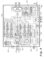
- FIG. 3 illustrates the operation of an ASP 400 in accordance with the present invention.
- the ASP 400 comprises four main building blocks, namely, a low noise and high common mode rejection ratio (CMRR) readout channel 410, two band-power extraction channels 420, an impedance readout circuit 430 and an adaptive sampling (AS) ADC 440.
- the CMRR readout channel 410 extracts ECG signals.
- the power extraction channels 420 extract signal fluctuations in a specified frequency band.
- the impedance readout circuit 430 monitors electrode-tissue contact impedance at the same time as the biopotential signals, for example, the ECG signals are being monitored.
- the AS-ADC 440 reduces the equivalent data rate of the ECG readout channel 410.
- the ASP 400 also includes two low frequency oscillators 450, 455, a high frequency oscillator 460, a bias circuit generator 465 and configuration registers 470.
- the low frequency oscillators 450, 455 operate at 8kHz and the high frequency oscillator 460 operates at 1 MHz.
- the oscillators 450, 455, 460 provide inputs for a digital control circuit 475.
- the digital control circuit 475 supplies frequency and control signals for the ECG readout channel 410, the band power extraction channels 420 and the impedance readout circuit 430 as shown.
- the ECG readout channel 410 extracts the biopotential signals as an ECG signal 412 that is compressively sampled by the AS-ADC 440. This minimises the equivalent output data rate of the ASP output which in turn reduces the power consumption of the DSP and radio or wireless data transmission ( Figure 2 ).
- the band power extraction channels 420 implement a band-pass filter for extracting signal fluctuations in the selected or specified frequency band. This enables the detection of ECG signal features with very low power consumption. This has been described in " A 60 ⁇ W 60nV/ ⁇ Hz Readout Front-end for Portable Biopotential Acquisition Systems" by RF Yazicioglu, P Merken, R Puers and C Van Hoof, IEEE J. Solid-State Circuits, vol. 42, no. 5, pages 110 to 1110, May 2007 .
- the ASP 400 also includes a current stimulation block 480 that stimulates an electrode-tissue interface (not shown) with an AC current.
- the resulting voltage is amplified by the impedance readout circuit 430 to extract imaginary and real components of the electrode-tissue impedance. This enables the system to monitor continuously the ECG signal integrity against lead connectivity and motion-induced signal artefacts.
- the sampling frequencies for signal components in the ASP 400 can be as shown in Table 1 below. Table 1.
- Signal component Sampling frequency (Hz) Band power imaginary 64
- Band power real 64 Impedance imaginary 250 Impedance real 250 ECG 64 or 1024 (adaptive sampling)
- Solid-State Circuits vol. 43, no. 12, pages 3025 to 3038, December 2008 , " 2 ⁇ W 100nV/ ⁇ Hz Chopper Stabilised Instrumentation Amplifier for Chronic Measurement of Neural Field Potentials” by T Denison, K Consoer, W Santa, A Avestruz, J Cooley and A Kelly, IEEE J. Solid-State Circuits, vol. 42, no. 12, pages 2934 to 2945, December 2007 , and " A Micro-Power EEG Acquisition SoC with Integrated Feature Extraction Processor for a Chronic Seizure Detection System” by N Verma, A Schoeb, J Bohorquez, J Dawson, J Guttag and AP Chandrakasan, IEEE J. Solid-State Circuits, vol. 45, no. 4, pages 804 to 816, April 2010 .
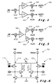
- FIG. 4 an arrangement 500 is shown in which an input signal 510 is divided into two signal paths 520, 530.
- Each signal path 520, 530 has an associated IA 540, 550 for providing respective output signals 560, 570. Whilst this arrangement enables flexible and independent demodulation for each signal path 520, 530, there is an associated increase in the overall power consumption.
- FIG. 5 illustrates a chopper modulated IA 600 that provides good trade-off between power dissipation and architectural flexibility for the implementation of different functionalities.
- a single input signal 610 is divided into two signal paths 620, 630 as shown.
- This IA 600 provides two output signals 640, 650 without the need for an IA in each signal path 620, 630.
- the chopper modulated IA 600 includes a transconductance (TC) input stage 660 that drives two output transimpedance (TI) stages 670, 680. Whilst only two output TI stages 670, 680 are shown, it will be appreciated that more than two such stages may be driven from a single TC input stage 660.
- TC transconductance
- TI output transimpedance
- a chopper modulator is inserted before the input stage and the demodulators can be included in the output stages. This isolates the different output stages and allows the implementation of independent signal paths that are tailored to extract different properties of the same input signal. On the other hand, reducing the number of IA input stages minimises the contribution of the IA to the total power consumption of the ASP ASIC ( Figure 3 ).
- FIG. 6 an architecture of an input TC stage 700 is shown.
- This stage 700 is equivalent to the TC stage 660 shown in Figure 5 .
- An input differential signal 710, 720 is copied to terminals 715, 725 of resistor R 1 .
- the current, I R1 deflects the currents of transistors M3 and M4 by the same amount.
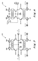
- Figure 7 illustrates an architecture of a fully-differential TI output stage 800
- Figure 8 illustrates an architecture of a single-ended TI output stage 900.
- Equation (4) indicates that the noise and respective power consumption can be optimised by forcing the transistors MC, M3 and M5 to operate in strong inversion.
- the design consideration for the input DR is according to Table 2 above.
- the lAs for the extraction of ECG signals should be capable of rejecting ⁇ 300mV DC polarization voltage (PV) from the biopotential electrodes.
- PV DC polarization voltage
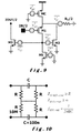
- the implemented IA uses a floating high-pass filter as shown in Figure 10 .
- a floating high-pass filter is also described in " AC-Coupled Front-End for Biopotential Measurements" by EM Spinelli, R Pallas-Areny and MA Mayosky, IEEE Trans. on Biomedical Eng., vol. 50, no. 3, March 2003 .
- the main advantage of using a floating high-pass filter compared to conventional passive high-pass filters is the elimination of the grounded resistor, thereby implementing very large common mode input impedance. This is specifically important to sustain the CMRR of the system under large electrode impedance mismatches.
- the resistors are used before the capacitors to sense the average DC potential of the input leads. This is set by a ground electrode described below with reference to Figure 28 below.
- the common mode input impedance is only defined by parasitic capacitances.
- the characterization of the IA is performed at the output of the ECG readout channel.
- Figure 11 shows that the measured input-referred noise of the IA is 85nV rms / ⁇ Hz, mainly dominated by the input transistors M1 and M2, and the resistor R 1 .
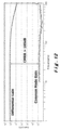
- Figure 12 shows the CMRR measurement using a 600mVpp common mode input signal, which corresponds to a CMRR larger than 105dB in the measurement bandwidth.
- the differential input impedance of the IA is defined by the off-chip high-pass filter, which is 10M ⁇ .
- the noise-efficiency-factor (NEF) of the IA can be calculated as 5.0 while using a single TI input stage and a single TC output stage.
- NEF is described in " A Micropower Low-Noise Monolithic Instrumentation Amplifier for Medical Purposes" by MSJ Steyaert, WMC Sansen and C Zhongyuan, IEEE J. Solid-State Circuits, vol. sc-22, no. 6, lines 1163 to 1168, December 1987 .
- the equivalent NEF of the IA reduces to 4.0 and 3.6 for two and three output stages respectively.
- a fundamental requirement for an ECG monitoring system is the detection of the ECG beat (QRS Complex). This is performed by extracting the features of the QRS complex, which is used as an input to a beat detection algorithm.
- QRS Complex a fundamental requirement for an ECG monitoring system.
- a high performance but rather power hungry feature extraction method is the Continuous Wavelet Transform (CWT) as described in " Low-Power Robust Beat Detection in Ambulatory Cardiac Monitoring" by I Romero, B Grundlehner, J Penders, J Huisken and YH Yassin, IEEE BioCAS, pages 249 to 252, November 2009 .
- CWT Continuous Wavelet Transform
- the power consumption can be lowered by implementing the wavelet filters in the analog domain, while limiting the configurability to different scales.
- a different approach is used that simply uses a band-pass filter to extract the features of the ECG signal.
- the band-pass filter characteristics are optimised over the MIT-BIH Arrhythmia Database (www.physion.org/physioback/database/mitdb ) and the use of the heterodyne chopper readout is selected as the power efficient and configurable implementation of a band-pass filter as is described in "A 5 ⁇ W/Channel Spectral Analysis IC for Chronic Bidirectional Brain-Machine Interfaces" mentioned above.
- FIG 13 shows the architecture of a complete beat detection system 1400 utilising the heterodyne chopping readout circuit in the ASP 400 ( Figure 3 ) for extracting the band-power for detecting the QRS complex and referring to the ECG readout channel 410 ( Figure 3 ) for detecting the location of the R-peak.
- the beat detection system 1400 comprises an ASP 1410 connected to a DSP 1420.
- the ASP 1410 receives an input signal 1430 which it processes to extract quadrature components 1440, 1450 of the ECG signal fluctuations in the selected frequency band (corresponding to band power channels 420 in Figure 3 ) and extracts a time domain ECG signal 1460 (corresponding to ECG channel 410 in Figure 3 ).
- the extracted components 1440, 1450 and the ECG signal 1460 are digitised by an ADC 1470 (corresponding to AS-ADC 440 in Figure 3 ).
- the digitised components and signals are passed to the DSP 1420 for further processing.
- the DSP calculates the band-power by taking the sum-of-squares of the quadrature channels 1440, 1450. This band-power is used as an input 1475 to a beat detection algorithm 1480.
- the beat detection algorithm 1480 detects the presence of the QRS complex 1432, 1434 in input signal 1430 and refers to the digitised time-domain ECG signal 1460 to find the exact location of the R peak within the input signal 1430.
- a single TC input stage is used for the implementation of the three readout channels for beat detection.
- Such an architecture reduces the required current consumption of the implemented IA from 4.2 ⁇ A (two fully differential IA plus a single-ended IA) to 2.2 ⁇ A (a single TC input stage with 2 fully differential and 1 single-ended TI output stages).
- the ECG signals measured from electrodes (IN+, IN-) are modulated at the input to the ASP 1410 with an in-phase clock, f(0°), 1436.
- the in-phase clock 1436 operates at a frequency of 1 kHz.
- the modulated ECG signal is demodulated with a frequency offset ( ⁇ ) at the output of two TI stages 1442 and 1452, where ( ⁇ ) defines the center of the band-pass filter.
- the quadrature demodulation clocks enable the extraction of the imaginary and real components.
- the width of the band-pass filter is defined by the switched capacitor (SC) low-pass filter (LPF) 1444 positioned after the demodulators 1442, 1452.
- the filtered components are then amplified by PGA 1446 and filtered again by filter 1448. It will be appreciated that although only the band-power I channel has been labeled, identical components can also be used in the band-power Q channel.
- FIG 14 shows a switched capacitor (SC) low-pass filter (LPF) 1500 that is used for filtering the quadrature components 1440, 1450 of Figure 13 in more detail.
- the SC LPF 1500 provides a good trade-off between area and noise performance. In order to reduce the noise, the SC LPF is operated at four times the chopper demodulation frequency, that is, 4(f+ ⁇ ).
- the SC LPF 1500 comprises three cascaded programmable capacitor stages 1510, 1520, 1530 - only stage 1510 being shown in detail. Each capacitor stage 1510, 1520, 1530 comprises an SC RC filter.
- SC LPF 1448 having a cut-off frequency of 12Hz rejects the modulated noise of the PGA 1446.
- FIG 15 shows a programmable gain amplifier (PGA) 1600 that is used for amplifying the quadrature components 1440, 1450 of Figure 14 in more detail.
- the PGA 1600 of the band-power extraction channel (420 in Figure 3 ) is implemented using a chopper modulated capacitive amplifier with three electronically selectable gains of 20, 41 and 83. Due to the large source impedance from the SC LPF 1500 ( Figure 14 ), the inputs of the PGA 1600 are buffered after input modulator 1610. The modulation frequency is kept relatively low, for example, at 128Hz, to minimise the loading of the SC LPF 1500 ( Figure 15 ).
- the gain of the PGA 1600 is controlled by the positions of the switches G 1 and G 2 . Three gain settings are available with this embodiment as follows:- G 1 G 2 Gain 0 0 83 0 1 41 1 1 20
- the implementation of the ECG readout channel in Figure 13 employs the same input TC stage of the band-power extraction channels.
- the output stage uses the single-ended TI stage 1462 as shown.
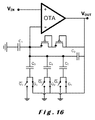
- the back-end PGA 1464 is implemented using a capacitive amplifier as shown in Figure 16 and is described in "A Low-Power Low-Noise CMOS Amplifier for Neural Recording Applications” mentioned above.
- the gain programmability is integrated using the flip-over architecture as described in " A 1V 450nW Fully Integrated Programmable Biomedical Sensor Interface System” by XD Zou, XY Xu, LB Yao and Y Lian, IEEE J. Solid-State Circuits, vol. 44, no 4, pages 1067 to 1077, April 2009 .
- the PGA has electronically settable gains of 3, 5, 9, and 13, setting the gain of the ECG channel to 300, 500, 900, and 1300 respectively.
- the DC gain of the PGA is 1.
- the heterodyne chopper readout uses 1 kHz as the modulation frequency.
- Figure 17 shows the measured band-pass filter characteristics of the heterodyne chopper readout circuit.
- the offset frequency ( ⁇ ) is set to 16Hz using the internal low-frequency oscillators of the ASIC 400 ( Figure 3 ), whereas the width of the band can be set from twice 2.3Hz to twice 3.9Hz with four steps.
- the low-range of the settings has an offset from the ideal 1.8Hz value, possibly due to the effect of the parasitic capacitance.
- the solid line indicates the characteristics used in the measurements.
- Figure 18 shows the extraction of the band-power in a real ECG recording application using the minimum bandwidth setting of the filter.
- Upper trace 1904 shows the extracted ECG signal and lower trace 1906 shows the calculated band-power using the band-power quadrature components provided by the ASIC 400 in Figure 3 .
- heterodyne chopping amplifiers folds the odd harmonics of the offset frequency ( ⁇ ) as described in "A 5 ⁇ W/Channel Spectral Analysis IC for Chronic Bidirectional Brain-Machine Interfaces" mentioned above, into the measurement band with 1/n 2 scaling. Although this has minor significance for QRS detection, which has the highest frequency components in the ECG signal, it may present a problem, if heterodyne chopping is intended to be used for monitoring P or T waves, in the presence of large QRS complex signal.
- Figure 19 shows an enlarged view of the power peak 1910 of Figure 18 .
- the power characteristics for the I and Q components can be seen.
- the sampling rate of ECG signals is conventionally selected according to the high frequency region, that is, the QRS complex, and the requirements of the application.
- HRV heart rate variability
- HRV heart rate variability
- This can benefit from higher sampling rates than the commonly accepted 256Hz sampling rate of portable ECG monitoring devices.
- HRV heart rate variability
- such constant sampling rate over the entire ECG signal significantly increases the processing load of systems.
- Significant data compression without loss of information can be achieved if the sampling frequency of the ECG signals can be adapted according to the activity of the signal as illustrated in Figure 20 .
- Time samples of an ECG signal 2110 are illustrated by dots in upper trace 2120. In trace 2120, two QRS complex portions 2130, 2140 are shown with an R-R interval 2150.
- Lower trace 2160 illustrates the comparator output where a high frequency, f H , is selected for the QRS complex 2130, 2140 and a lower frequency, f L , is used for the period between the S of complex 2130 and the Q of complex 2140.
- FIG 21 shows the architecture of an AS-ADC 2200.
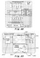
- An ADC 2210 is core to the architecture and comprises an 11-bit Successive Approximation ADC (SAR-ADC) using split-DAC (as shown in Figure 23 ) to reduce the silicon area (" A Segmented ⁇ 255 Law PCM Voice Encoder Uitlising NMOS Technology" by Y Tsividi et al., IEEE J. Solid-State Circuits, vol. 11, no.
- the adaptive sampling of an input signal 2230 is controlled by an Activity Detector (ACTDET) circuit 2240 that senses the rate of change of the input signal by using a SC differentiator 2242.
- the output of the differentiator 2242 is compared to a threshold voltage in comparator 2220 to select between a low sampling rate, f L, and a high sampling rate, f H , in a selector 2250.
- the low and high sampling rates in this embodiment are respectively 64Hz and 1024Hz.
- the threshold voltage can be an adaptive threshold that is determined from the heart rate being monitored as described below with reference to Figure 31 .
- the differentiator 2242 uses switched capacitor (SC) topology described in "New Monolithic Switched-Capacitor Differentiators with Good Noise Rejection” by C-Y Wu, T-C Yu and S-S Chang, IEEE J. Solid-State Circuits, vol. 24, no. 1, pages 177 to 180, 1989 where the clock frequency is selected as 250Hz and two differentiators operating in alternating clock phases are connected in parallel.
- SC switched capacitor
- Simulations using Spectre RF indicate a maximum group delay of 2.5ms at the output of the differentiator 2242, setting the delay between the detection of the high frequency activity and changing of the ADC sampling rate to this value. This delay is considered not to be significant as most portable recording systems rely on 256Hz constant sampling rate setting the time accuracy of the same transition region to ⁇ 4ms.
- the amplitude and morphology of ECG signals varies significantly, leading to variations in the rate of change information. This necessitates the use of an adaptive threshold.
- the adaptive threshold generation relies on the periodic nature of the ECG signals as shown in Figure 20 .
- the function of the ACTDET 2240 is to detect the high frequency activity, that is, the presence of the QRS complex, and to control the ADC sampling frequency. This means that the comparator output pulse should have the same duration and period as the QRS complex of the ECG signals. If the duty cycle of the comparator output pulse can be represented by V AVG (shown in the lower trace 2160 of Figure 20 ), an ideal value of V AVG can be calculated from the heart rate information extracted using the beat detection algorithm 1480 in Figure 13 and the morphological definition of the QRS width of between 40ms and 120ms as defined by the ANSI/AAMI-EC13 standard.
- the ACTDET 2400 comprises a differentiator stage 2410, a comparator stage 2420, a selector stage 2430 and an adaptive threshold generator stage 2440.
- the differentiator stage 2410 is as described above with reference to Figure 21 .
- the adaptive threshold generator stage 2440 forms part of a negative feedback loop in which the output from the comparator stage 2420 is filtered using a LPF 2442 to provide one input to a comparator 2444, V LPF .
- V LPF s s p s + 1 + A ⁇ s p ⁇ V IN s ⁇ H s + A ⁇ V AVG
- the LPF can be implemented by an RC filter where the resistor, R, can be implemented using pseudo resistors as described in "A Low-Power Low-Noise CMOS Amplifier for Neural Recording Applications" mentioned above. This enables the implementation of a low-pass filter with very low cut-off frequency, averaging the comparator output over a long period.
- the use of a large loop gain, for example, where A 10, sets V LPF to V AVC and reduces the effect of the SC differentiator output on the threshold voltage.
- Figure 24 illustrates the generation of a sample and convert signal for the AS-ADC 2200 of Figure 21 .
- Trace 2510 shows the low frequency sampling signal, flu of 64Hz;
- trace 2520 shows the high frequency sampling signal, f H , of 1024Hz;
- trace 2530 shows the output from the comparator 2220;
- trace 2540 shows the sample and convert signals for the ECG channel. In between the high frequency sampling signals, other ASIC channels not requiring the high frequency sampling can be converted.
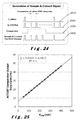
- a sinusoidal signal is fed to the input of the ADC and the duty cycle of the comparator output pulse is monitored, while changing the V AVC input of the ACTDET block 2240 in Figure 21 .
- Figure 25 shows the linear relation between the duty cycle of the comparator output pulse and the input V AVG . This enables the setting of the width of the comparator output pulse to the ideal width of the QRS complex once the average beat-to-beat interval is known.
- Figure 26 shows the effect of changing the V AVG while sampling a synthetic ECG signal at 60 beats-per-minute. Real life operation is shown in Figure 32 .
- the ideal value of the comparator output duty cycle is calculated to be between 4% and 12% (QRS complex width is between 40ms and 120ms as described in the ANSI/AAMI-EC13 standard mentioned above.
- the average beat-to-beat duration is 1 s.
- bottom trace 2710, V AVC is selected as 15mV causing the ADC to increase the sampling rate from 64Hz to 1024Hz only during the presence of the QRS complex. This has a compression ratio of 1:7.3 with respect to a constant 1024Hz sampling rate.
- V AVG is increased to 110mV, 215mV, and 415mV respectively increasing the duty cycle of the high frequency sampling rate, each trace corresponding to compression ratios of 1:4.4, 1:3.0 and 1:2 respectively with respect to a constant 1024Hz sampling rate.
- the pulse overlaid on each trace shows the regions sampled with at the high sampling rate of 1024Hz.
- Inset 2750 shows the delay between the start of the QRS complex and switching to the high frequency sampling rate for each of the traces 2710, 2720, 2730 and 2740.
- Trace 2760 is also shown in Figure 27 for a V AVC of 1000mV and a compression ratio of 1:1 with respect to a constant 1024Hz sampling rate.
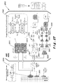
- FIG. 27 shows the architecture of the impedance measurement circuit 2800 for continuously monitoring the electrode-tissue contact impedance simultaneously with the biopotential signals.
- Chopper modulation is used to generate the AC stimulation current and separate the impedance measurement frequency from the biopotential signal frequency. This eliminates the need for power hungry sinusoidal oscillators and analogue multipliers as described in "Active Motion Artifact Cancellation for Wearable Health Monitoring Sensors using MEMS Accelerometers” mentioned above; “ An Approach to Reliable Motion Artifact Detection for Mobile Long-Term ECG Monitoring Systems using Dry Electrodes” by J Ottenbacher, M Kirst, L Jatoba, U Gro ⁇ man and W Strok, Proc.
- the impedance measurement circuit 2800 consists of two AC stimulation current sources 2810, 2815 and an impedance readout circuit 2820.
- the impedance readout circuit 2820 provides two quadrature readout signals 2822, 2824 that correspond to the imaginary and real parts of an electrode-tissue interface 2830.
- An ECG channel 2830 is also shown.
- the AC current sources 2810, 2812 are generated by multiplexing between a current source I DC,source , and a current sink I DC,sink at the same frequency, f, as the chopper modulators in the ECG and impedance readout channels 2820, 2830.
- Chopper stabilised AC current generation is shown in more detail in inset 2840.
- I DC,source should match to I DC,sink . This is accomplished by chopper stabilising the current mirrors M 1 - M 2 and N 1 - N 2 at twice the operating frequency of the chopper modulator, 2f.
- the phase of a single current source can be selected between 0° and 180°.
- the former leads to the generation of a common-mode stimulation current that can be used to monitor the impedance difference between two electrodes 2850, 2852 and the latter leads to the generation of a differential stimulation current that can be used to measure the total impedance of the measurement electrodes 2850, 2852.
- the stimulation current is adjustable between 11nApp and 100nApp with 9 steps.
- the quadrature impedance readout channel 2820 utilises a single input TC stage 2825 and two output TI stages 2826, 2827. Similar to the heterodyne readout described above, this minimises the current consumption of the IA implementation to 1.8 ⁇ A for a single TC stage with two output TI stages.
- the demodulators inside the TI output stages 2826, 2827 are operating at the same frequency as the square wave current sources, that is, at 1 kHz. This way the AC voltage generated over the electrode-tissue interface 2830 can be demodulated to the baseband, whereas the ECG signal at the baseband can be modulated and rejected by a low-pass filter 2828, 2829.
- ECG readout channel 2860 sustains the impedance voltage at modulation frequency and thus it can be rejected by a low-pass filter.
- input modulator 2862 of the ECG readout channel 2860 also demodulates the impedance signal to the base-band.
- a DC servo 2864 is included in the ECG readout channel 2860. This DC servo 2864 filters both the offset of the IA, as described in "A 60 ⁇ W 60nV/ ⁇ Hz Readout Front-end for Portable Biopotential Acquisition Systems" mentioned above, and the impedance signal demodulated to the baseband after the input modulator of the ECG readout channel 2860.
- PGAs 2821, 2831 of the impedance readout channel 2820 uses the same architecture as PGA 2866 of the ECG readout channel 2860 as described above with reference to Figure 16 implementing electronically selectable gains of 3, 5, 9 and 13.
- the high-pass filtering nature of the PGA with a DC gain of 1 enables the amplification of AC impedance changes while still allowing monitoring of the DC impedance of the electrode-tissue interface. This is crucial for detecting electrode connectivity.
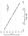
- Figure 28 shows the characterisation of the impedance measurement channel 2820 using off-chip resistors.
- Two resistors are connected to the input leads of the ASIC 400 ( Figure 3 ), two AC current stimulation sources are set to 100nApp with same phase, and the output of the impedance measurement channel (real) is monitored.
- the output voltage shows a linear change together with the changing impedance of the impedance measurement channel.
- the fitted curve to the measurements indicates that the stimulation current for the measurement of the impedance is 56nA, close to the desired value of 50nA. Note that the total gain at the output of the channel is 100 since PGA gain is 1 for DC inputs.
- the equivalent sensitivity of the impedance measurement channel is calculated as 1.7 ⁇ rms / ⁇ Hz for 100nApp stimulation current and 9 ⁇ rms / ⁇ Hz for 11 nApp stimulation current, while the total power consumed for the quadrature impedance measurement is less than 6.5 ⁇ W.
- a monitored ECG signal 3000 is shown together with an impedance measurement for the real component 3050.
- the two signal traces as shown comprise three regions 3010, 3020 and 3030 where the lead is either connected to the subject or not. Regions 3010 and 3030 show the results when the lead is connected and region 3020 show the results when the lead is no longer connected as it has fallen off. From this, it can be clearly determined when one of the measurement leads is disconnected, as the impedance readout channels give a clear indication of the presence of a disconnected lead.
- upper trace 3110 shows an ECG signal 3120 and lower trace 3130 shows reactance 3140 and resistance 3150.
- the imaginary and the real components of the impedance readout circuit show an impedance change, indicating the presence of motion artefacts.
- the measurements were taken with 100nApp current stimulation where both current sources are in-phase.
- the gain of the impedance readout channel was 1300.
- the ASP ASIC in accordance with the present invention has been implemented in a 0.5 ⁇ m standard CMOS process and includes the building blocks described above with reference to Figure 3 as follows: ECG and impedance channels; band-power channels; adaptive-based sampling; low frequency oscillators; high frequency oscillator; bias circuit generator; digital control circuit, stimulation current generator; and configuration registers. IA input stages and IA output stages are also included together with buffers.
- the ASP ASIC current consumption is reduced by 2 ⁇ A mainly due to the reduction in the ADC and SPI current consumption.
- Table 4 below shows a summary of the measured performance.
- Table 4. Supply Voltage 2V Common-Mode Rejection Ratio with floating HPF >105dB Chopper Stabilised Current Source Output 50nApeak - 5.5nApeak (9 settings) Input Referred Noise ECG Channel 85nV rms / ⁇ Hz Impedance Measurement 1.7 ⁇ rms / ⁇ Hz - 9 ⁇ rms / ⁇ Hz GAIN ECG Channel 300, 500, 900, 1300 (4 settings) Impedance Channels 300, 500, 900, 1300 (4 settings) Band-Power Extraction Channels 810, 1620, 3240 (3 settings) BANDWIDTH ECG Channel 170Hz, 140Hz (2 settings) Impedance Channels 50Hz Band-Power Extraction Channels 4.6Hz, 5.2Hz, 6Hz, 6.8Hz (centre frequency adjustable through LF oscillator) (-3dB of BPF) ADC DNL 0.3LSB INL 0.5LSB ENOB 10.6bits
- a portable and wireless ECG monitoring system has been developed using the ASP ASIC described above to perform real-time ECG monitoring, beat detection, and signal integrity monitoring. Such a system is shown in Figure 31 .
- a wireless ECG monitoring system 3300 comprises an ASP ASIC 3310, a low-power microcontroller ( ⁇ C) 3320 and a low-power radio 3330.
- ⁇ C low-power microcontroller
- a suitable ⁇ C is described at www.focus.ti.com/docs/prod/folders/print/msp430f123.html in "16-Bit Ultra-Low Power Microcontroller, 8kB Flash, 256B RAM, USART, Comparator", MSP430.
- a suitable low-power radio is described at www.nvlsi.no (Nordic-VLSI), "nRF2401A Ultra Low-Power 2.4GHz Transceiver.
- the ASP 3310 receives an input ECG signal 3340 that is processed by an ECG readout channel 3350, impedance measurement channels (real and imaginary) 3352, 3354, and band-power measurement channels (real and imaginary) 3356, 3358. Outputs from the impedance measurement channels 3352, 3354, and band-power measurement channels 3356, 3358 are passed to an ADC 3360 which samples the impedance measurement channels at 256Hz and the band-power channels at 64Hz. An adaptive sampling ADC 3365 is used for the ECG readout channel 3310 under the control of a V AVG signal from the ⁇ C 3320 at either 64Hz or 1024Hz as described above.
- the digitised signals are passed to a DSP 3370 where they are processed to provide beat detection 3372 and R peak location 3374. QRS detection 3376 is also carried out to provide an input for the R peak location 3374. The output from the R peak location 3374 is used to extract the heart rate 3378 for controlling the adaptive ADC 3365 and for transmission to a receiver (not shown) by means of the radio 3330.
- the ⁇ C 3320 also includes a system controller 3380 that provides control settings, for example, gain settings, system clock and oscillator calibration, for the ASP 3310.
- the system does not employ the ASP functionalities of the ASIC but rather only utilises the ECG readout channel in the ASP ASIC that is sampled at 256Hz.
- Raw ECG signals from the ECG readout channel are used for beat detection processing based on a continuous wavelet transform (CWT) and continuous streaming of the ECG signal over the radio or wireless link.
- the total power dissipation is shown as 3410 with the power dissipation for each of the main components being indicated as 3412 for the radio, 3414 for the controller, 3416 for the DSP and 3418 for the ASP.
- the system employs the ASP functionalities of the ASIC.
- the ⁇ C calculates the average heart rate using the R-R intervals and updates the V AVC of the AS-ADC.
- the adaptively sampled ECG signal is time stamped and transmitted over the wireless link together with the beat information.
- the total power dissipation is shown as 3420 with the power dissipation for each of the main components being indicated as 3422 for the radio, 3424 for the controller, 3426 for the DSP and 3428 for the ASP.
- the QRS detection relies on the feature extraction by CWT, which is the equivalent of the algorithm running in scenario #1.
- the total power dissipation is shown as 3430 with the power dissipation for each of the main components being indicated as 3432 for the radio, 3434 for the controller, 3436 for the DSP and 3438 for the ASP.
- the ⁇ C power consumption is split into the power consumption of the controller and DSP functions. It can be seen from the graph that the use of ASP functionality significantly reduces the DSP and radio power consumption both for the second and third scenarios.
- the DSP power dissipation can further be reduced by a factor of 2 by moving the IIR filter in the QRS detection 3376 ( Figure 31 ) of the DSP to the analogue domain.
- the power consumption of the third scenario is also significantly lower than that of the first, although both systems are running the same QRS detection algorithm.
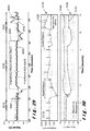
- Top trace 3510 shows the ECG signal illustrating a detected beat 3512, false detection 3514 due to motion artefact and a missed beat 3516 in the QRS complex.
- Traces 3520 and 3530 illustrate the quadrature components (imaginary and real respectively) of the impedance measurement channels. In trace 3520, there is an impedance change at 3522 and, in trace 3530, there is an impedance change at 3532 due to a motion artefact.
- Traces 3540 and 3550 illustrate the band-power quadrature components (imaginary and real respectively) of the band-power measurement channels.
- Fluctuations 3542 and 3552 are shown that correspond to the false detection 3514/missed beat 3516 scenario.
- Bottom trace 3560 illustrates pulses 62 that indicate the selection of sampling at the higher rate, that is, at 1024Hz.
- An increase in sampling rate due to the presence of a high frequency artefact is shown at 3564 and sampling QRS with high frequency at 3566.
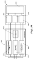
- an ASP 3600 in accordance with the present invention is shown together with a digital processor 3650 to which output signals from the ASP 3600 are connected.
- the ASP 3600 includes an ECG readout channel 3610 connected to an adaptive sampling unit or compression block 3620, a band power readout channel 3630 that provides quadrature output signals BPQ and BPI, and a continuous-time impedance monitoring channel 3640 that provides quadrature output signals IMPI and IMPQ as shown.
- the digital signal processor 3650 includes a band-power calculation block or unit 3660, a feature extraction block or unit 3670, an impedance calculation block or unit 3680 and a back-end processor 3690.
- the band-power calculation unit 3660 determines the power in the monitored ECG signal as described above and illustrated in Figure 19 and passes it to the back-end processor 3690.
- the impedance calculation unit 3680 calculates the impedance of the monitored ECG signal and passes it to the back-end processor 3690.
- the Compressed ECG signal from the compression block 3620 is processed by the feature extraction block 3670 and the output is passed to the back-end processor 3690.
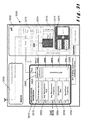
- Figure 35 illustrates a flow chart 3700 for turning on and turning off of a monitoring device in accordance with the present invention.
- the continuous impedance measurement of ECG signals using the continuous-time impedance monitoring channel 3640 ( Figure 36 ) is used to initiate activation of the device.
- the measured impedance, block 3710 is compared to a threshold value in block 3720. If the impedance value is greater than the threshold, the device is turned on and processing activities and wireless transmission can occur, block 3730. If the impedance value is greater than the threshold value, then the device iis turned off and processing activities and wireless transmission are disabled, block 3740.
- FIG 36 a flow chart 3800 for beat detection in a monitoring device in accordance with the present invention is shown.
- the output from a band power calculation, block 3810 is used as the input to a beat-detection algorithm 3820.
- the output of the beat-detection algorithm 3820 is filtered, block 3830, to remove false positives that are created by artefacts present in the ECG signal.
- Figure 37 illustrates a flow chart 3900 for the removal of artefacts from the ECG signal.
- the measured impedance, block 3910, and the ECG signal, block 3920 are passed to a filter 3930.
- Artefacts present in the ECG signal are removed using the impedance measurement in the filter, block 3930.
- the output from the filter is then passed to a low-power beat detection algorithm, block 3940, where beat detection is carried out on the filtered ECG signal.
- FIG 38 a flow chart 4000 for beat detection using a monitoring device in accordance with the present invention is shown.
- the first algorithm is low-power beat detection, block 4010, which uses the band-power calculation, block 4020, as an input to a beat-detection algorithm based on band power, block 4030. This provides an output signal that is tested for a consistent RR interval determination, block 4040.
- the second algorithm is a precise beat detection algorithm, block 4050, which is activated when the RR interval determination is inconsistent.
- the ECG signal, block 4060 either compressed as described with reference to Figure 35 above or not, is applied to a precise beat detection algorithm, block 4070.
- the precision beat detection algorithm, block 4070 is activated when block 4040 determines that the RR interval determination is not consistent so that a more consistent and/or accurate RR interval can be determined. [The RR interval is discussed above with reference to Figures 13 and 20 .]
- the low-power beat detection of block 4010 is used alone. However, if the RR interval is not consistently determined, an indication that the low-power beat detection algorithm is failing, then the precision beat detection algorithm, block 4050, is also used. A negative signal from block 4040 is used to activate the precise beat detection algorithm 4070 as shown. When the determination of the RR interval returns to being consistently determined, the precise beat detection algorithm 4070 is deactivated.
- FIG 39 illustrates a flow chart 4100 in which continuous impedance measurement is used in conjunction with the low-power beat detection algorithm and the precision beat detection algorithm.
- an impedance measurement block 4110
- An artefact detection algorithm block 4120
- the low-power beat detection algorithm 4140 is used for the determination of the beats in the input ECG signal.
- block 4130 activates the precision beat detection algorithm 4150 as described above with reference to Figure 38 .
- the precision beat detection algorithm is deactivated.
- the detection of the presence of motion artefacts using the impedance monitoring allows switching between the low-power beat detection algorithm and the precision beat detection algorithm.
- the precise beat detection algorithm uses more power than the low-power beat detection algorithm and a substantial amount of power can be saved if the low-power beat detection algorithm is used.
- the precise beat detection algorithm is only used where there is inconsistency, for example, inconsistency in the detection of the RR interval, or the presence of artefacts that may lead to false positives in the low-power beat detection algorithm.
- the monitoring device in accordance with the present invention also controls data transfer from the device to a network (not shown) via a radio or wireless link as described above with reference to Figure 33 .
- a flow chart 4200 is shown in which a compressed ECG signal, block 4210, obtained through adaptive sampling as described above, is processed, in block 4220, for feature extraction, storage and/or wireless transmission to a host network (not shown).
- beat detection is determined in block 4230.
- the signal is classified, block 4240, and any disorders present detected, block 4250. If no disorders are detected, no action is taken.
- a signal is transmitted to the host network, block 4220, using a radio or wireless transmission. The occurrence of the disorder can also be stored as a feature of block 4220.
- Data transfer can also be carried out continuously as shown in flow chart 4300 in Figure 41 .
- a compressed ECG signal is obtained through adaptive or activity based sampling, block 4310.
- the ECG signal is then processed in the back-end processor 3690 ( Figure 36 ), block 4320.
- the compressed sampled ECG signal can be stored continuously, processed continuously and/or transmitted wirelessly to the host network.
- a monitoring device including the ASP ASIC in accordance with the present invention can provide:-
- the ever increasing cost of healthcare requires a significant improvement in the delivery of healthcare efficiency.
- Remote monitoring of the patients proposes to tackle this problem, by using portable monitoring systems that have extended battery autonomy. It is especially required that these systems can perform reliable measurements, they have extended power autonomy, and also they are generic enough for reducing the costs.
- the ASP ASIC in accordance with the present invention addresses these constrains of portable ECG monitoring systems.
- the adaptive sampling and heterodyne chopper readout enables significant reduction in the overall data rate of the signal, assisting the DSP platforms to minimise their power dissipation yet keeping their generic nature to enable the implementation of different algorithms that can be used for different applications.
- the impedance measurement technique described that is, the use of chopper modulation for implementing impedance measurement circuits, eliminates the requirement for the sinusoidal current generation and reduces the power consumption of the impedance measurement circuits significantly, while enabling continuous time signal integrity monitoring.
- the ASP ASIC in accordance with the present invention merely consume 30 ⁇ W from 2V supply and leads to the development of a wireless ECG monitoring system that is more than four times more power efficient than its predecessors and sufficiently generic to allow the implementation of different ECG beat detection algorithms.
Landscapes
- Health & Medical Sciences (AREA)
- Life Sciences & Earth Sciences (AREA)
- Engineering & Computer Science (AREA)
- General Health & Medical Sciences (AREA)
- Veterinary Medicine (AREA)
- Biophysics (AREA)
- Biomedical Technology (AREA)
- Heart & Thoracic Surgery (AREA)
- Medical Informatics (AREA)
- Molecular Biology (AREA)
- Surgery (AREA)
- Animal Behavior & Ethology (AREA)
- Physics & Mathematics (AREA)
- Public Health (AREA)
- Pathology (AREA)
- Signal Processing (AREA)
- Cardiology (AREA)
- Artificial Intelligence (AREA)
- Computer Vision & Pattern Recognition (AREA)
- Physiology (AREA)
- Psychiatry (AREA)
- Dermatology (AREA)
- Nuclear Medicine, Radiotherapy & Molecular Imaging (AREA)
- Radiology & Medical Imaging (AREA)
- Power Engineering (AREA)
- Measurement And Recording Of Electrical Phenomena And Electrical Characteristics Of The Living Body (AREA)
Priority Applications (1)
| Application Number | Priority Date | Filing Date | Title |
|---|---|---|---|
| EP10176687.1A EP2298164B1 (de) | 2009-09-14 | 2010-09-14 | Vorrichtung zur kardialen Überwachung mit adaptiven Probenentnahme |
Applications Claiming Priority (4)
| Application Number | Priority Date | Filing Date | Title |
|---|---|---|---|
| US24229909P | 2009-09-14 | 2009-09-14 | |
| EP10152299.3A EP2294979B1 (de) | 2009-09-14 | 2010-02-01 | Verfahren und elektronisches medizinisches Gerät für simultane Messung sowie Impedanz und Biopotenzialsignal |
| US36529610P | 2010-07-16 | 2010-07-16 | |
| EP10176687.1A EP2298164B1 (de) | 2009-09-14 | 2010-09-14 | Vorrichtung zur kardialen Überwachung mit adaptiven Probenentnahme |
Publications (3)
| Publication Number | Publication Date |
|---|---|
| EP2298164A2 true EP2298164A2 (de) | 2011-03-23 |
| EP2298164A3 EP2298164A3 (de) | 2011-12-21 |
| EP2298164B1 EP2298164B1 (de) | 2013-05-15 |
Family
ID=46545550
Family Applications (1)
| Application Number | Title | Priority Date | Filing Date |
|---|---|---|---|
| EP10176687.1A Not-in-force EP2298164B1 (de) | 2009-09-14 | 2010-09-14 | Vorrichtung zur kardialen Überwachung mit adaptiven Probenentnahme |
Country Status (2)
| Country | Link |
|---|---|
| US (1) | US8862210B2 (de) |
| EP (1) | EP2298164B1 (de) |
Cited By (12)
| Publication number | Priority date | Publication date | Assignee | Title |
|---|---|---|---|---|
| EP2589332A1 (de) | 2011-11-03 | 2013-05-08 | Imec | System und Verfahren zur Analyse von Elektrokardiogrammsignalen |
| EP2591720A1 (de) * | 2011-11-08 | 2013-05-15 | Imec | Biomedizinisches Erfassungssystem mit Bewegungsartifaktreduktion |
| EP2767230A1 (de) | 2013-02-15 | 2014-08-20 | Imec | Schaltung, System und Verfahren für Impedanzmessungen |
| US9203422B2 (en) | 2011-09-29 | 2015-12-01 | Ecole Polytechique Federale De Lausanne (Epfl) | Low distortion switched-capacitor event-driven analog to digital converter |
| EP2974652A1 (de) * | 2014-07-17 | 2016-01-20 | Samsung Electronics Co., Ltd. | Verfahren und Vorrichtung zur Messung von Bioimpedanz |
| US9626521B2 (en) | 2014-04-16 | 2017-04-18 | Arizona Board Of Regents On Behalf Of Arizona State University | Physiological signal-based encryption and EHR management |
| US9642543B2 (en) | 2013-05-23 | 2017-05-09 | Arizona Board Of Regents | Systems and methods for model-based non-contact physiological data acquisition |
| US10238885B2 (en) | 2012-04-13 | 2019-03-26 | Health Alert, Llc | Outpatient health emergency warning system |
| CN109767392A (zh) * | 2018-12-05 | 2019-05-17 | 上海联影医疗科技有限公司 | 医学图像处理方法和系统、存储介质及计算机设备 |
| EP3967230A1 (de) * | 2020-09-09 | 2022-03-16 | MediaTek Inc. | Elektroden-gewebe-impedanzsystem zur direkten abtastung und zugehöriges signalverarbeitungsverfahren |
| US11430220B2 (en) | 2018-06-14 | 2022-08-30 | Shanghai United Imaging Healthcare Co., Ltd. | Methods and systems for image processing |
| WO2023105201A1 (en) * | 2021-12-07 | 2023-06-15 | Prevayl Innovations Limited | Electronics module, a controller for an electronics module and a method performed by a controller |
Families Citing this family (30)
| Publication number | Priority date | Publication date | Assignee | Title |
|---|---|---|---|---|
| EP2294978B1 (de) * | 2009-09-14 | 2013-09-04 | Imec | Adaptive Probenentnahme eines Elektrokardiogramms |
| US10004406B2 (en) | 2010-09-30 | 2018-06-26 | Fitbit, Inc. | Portable monitoring devices for processing applications and processing analysis of physiological conditions of a user associated with the portable monitoring device |
| ES2569683T3 (es) * | 2011-06-20 | 2016-05-12 | The Regents Of The University Of California | Sistema de registro de neuronas |
| US8878570B2 (en) * | 2011-09-30 | 2014-11-04 | Silicon Laboratories Inc. | Configurable analog front end |
| CN103505202A (zh) * | 2012-06-27 | 2014-01-15 | 天津宇迪智能技术有限公司 | 心、脑电信号同步采集的心脑耦合系统 |
| US8755873B2 (en) | 2012-09-21 | 2014-06-17 | Welch Allyn, Inc. | Evaluation of the quality of electrode contact with a skin surface |
| US9351653B1 (en) * | 2012-11-29 | 2016-05-31 | Intan Technologies, LLC | Multi-channel reconfigurable systems and methods for sensing biopotential signals |
| US9728059B2 (en) | 2013-01-15 | 2017-08-08 | Fitbit, Inc. | Sedentary period detection utilizing a wearable electronic device |
| US10039460B2 (en) | 2013-01-22 | 2018-08-07 | MiSleeping, Inc. | Neural activity recording apparatus and method of using same |
| US9662025B2 (en) * | 2013-05-03 | 2017-05-30 | The Florida International University Board Of Trustees | Low noise analog electronic circuit design for recording peripheral nerve activity |
| SG11201510134YA (en) * | 2013-06-12 | 2016-01-28 | Agency Science Tech & Res | Real-time multi-functional ecg signal processing system, dspe for the ecg signal processing system, and method thereof |
| KR102255204B1 (ko) * | 2013-08-28 | 2021-05-24 | 삼성전자주식회사 | 재구성 가능한 측정 장치 및 그 장치를 제어하는 방법 |
| US9456763B2 (en) * | 2013-09-11 | 2016-10-04 | Medtronic, Inc. | Apparatus and method for simultaneous capture of biopotential and tissue impedance signals |
| WO2016050551A1 (en) * | 2014-09-30 | 2016-04-07 | Koninklijke Philips N.V. | Wearable device for skin conductance measurement |
| DK3232922T3 (da) * | 2014-12-19 | 2022-03-14 | T&W Eng A/S | Aktiv elektrode omfattende en forstærker med closed-loop-enhedsforstærkning med choppermodulation |
| WO2016134473A1 (en) | 2015-02-27 | 2016-09-01 | Icentia Inc. | Wearable physiological data acquirer and methods of using same |
| EP3170450B1 (de) | 2015-11-18 | 2019-05-08 | Samsung Electronics Co., Ltd. | Pflaster mit einem externen schwebender hochpassfilter und elektrokardiograph (ekg)-pflaster damit |
| US11444646B1 (en) * | 2015-12-31 | 2022-09-13 | Neurowave Systems Inc. | Physiological signal acquisition system and method with improved noise and common mode rejection performance and signal quality |
| US10702184B2 (en) | 2017-06-07 | 2020-07-07 | Analog Devices International Unlimited Company | Low power measurement of skin electrical properties |
| WO2019060298A1 (en) | 2017-09-19 | 2019-03-28 | Neuroenhancement Lab, LLC | METHOD AND APPARATUS FOR NEURO-ACTIVATION |
| US11717686B2 (en) | 2017-12-04 | 2023-08-08 | Neuroenhancement Lab, LLC | Method and apparatus for neuroenhancement to facilitate learning and performance |
| US11478603B2 (en) | 2017-12-31 | 2022-10-25 | Neuroenhancement Lab, LLC | Method and apparatus for neuroenhancement to enhance emotional response |
| US12280219B2 (en) | 2017-12-31 | 2025-04-22 | NeuroLight, Inc. | Method and apparatus for neuroenhancement to enhance emotional response |
| US11364361B2 (en) | 2018-04-20 | 2022-06-21 | Neuroenhancement Lab, LLC | System and method for inducing sleep by transplanting mental states |
| EP3581100A1 (de) * | 2018-06-11 | 2019-12-18 | Polar Electro Oy | Bioimpedanzmesskonfiguration |
| US11452839B2 (en) | 2018-09-14 | 2022-09-27 | Neuroenhancement Lab, LLC | System and method of improving sleep |
| US11786694B2 (en) | 2019-05-24 | 2023-10-17 | NeuroLight, Inc. | Device, method, and app for facilitating sleep |
| RU2759404C1 (ru) * | 2020-11-26 | 2021-11-12 | Федеральное государственное автономное образовательное учреждение высшего образования "Национальный исследовательский Нижегородский государственный университет им. Н.И. Лобачевского" | Аппаратно-программный комплекс электрокардиографических измерений |
| CN114661081B (zh) * | 2020-12-22 | 2024-05-03 | 深圳英集芯科技股份有限公司 | 电源软启动控制电路、控制芯片及控制装置 |
| CN115754432B (zh) * | 2022-12-09 | 2026-02-06 | 思瑞浦微电子科技(苏州)股份有限公司 | 一种电流检测电路 |
Citations (1)
| Publication number | Priority date | Publication date | Assignee | Title |
|---|---|---|---|---|
| US20080269631A1 (en) | 2007-04-30 | 2008-10-30 | Medtronic, Inc. | Seizure prediction |
Family Cites Families (22)
| Publication number | Priority date | Publication date | Assignee | Title |
|---|---|---|---|---|
| US729168A (en) | 1902-08-06 | 1903-05-26 | Henry T Henderson | Ball-coupling. |
| US3667056A (en) | 1970-11-17 | 1972-05-30 | Instrumentation Specialties Co | Sample, hold, and subtract circuit |
| US4610254A (en) | 1984-03-08 | 1986-09-09 | Physio-Control Corporation | Interactive portable defibrillator |
| DE3509118C2 (de) | 1985-03-14 | 1994-03-24 | Bosch Gmbh Robert | Verfahren und Vorrichtung zur Messung des Durchsatzes eines ein Rohr durchströmenden Mediums |
| US5020541A (en) | 1988-07-13 | 1991-06-04 | Physio-Control Corporation | Apparatus for sensing lead and transthoracic impedances |
| US5197479A (en) | 1991-05-13 | 1993-03-30 | Mortara Instrument | Automatic electrode channel impedance measurement system for egg monitor |
| US5263486A (en) | 1991-11-01 | 1993-11-23 | Telectronics Pacing Systems, Inc. | Apparatus and method for electrocardiogram data compression |
| US5381803A (en) | 1993-03-12 | 1995-01-17 | Hewlett-Packard Corporation | QRS detector for defibrillator/monitor |
| US5836982A (en) | 1997-02-19 | 1998-11-17 | Medtronic, Inc. | System and method of data compression and non-linear sampling for implantable and battery-powered devices |
| US6812254B1 (en) * | 1999-09-29 | 2004-11-02 | Medical Merchandising Inc. | Pain reliever and method of use |
| JP2001198098A (ja) | 2000-01-21 | 2001-07-24 | Tanita Corp | むくみ測定方法及びむくみ測定装置 |
| US6821254B2 (en) | 2000-07-21 | 2004-11-23 | Institute Of Critical Care Medicine | Cardiac/respiratory arrest detector |
| BR0210833A (pt) | 2001-07-06 | 2004-06-22 | Aspect Medical Systems Inc | Sistema e método para a medição de impedância bioelétrica na presença de interferência |
| EE04767B1 (et) | 2002-12-06 | 2007-02-15 | Tallinna Tehnika�likool | Meetod ja seade elektrilise bioimpedantsi mõõtmiseks |
| AU2003902187A0 (en) | 2003-05-08 | 2003-05-22 | Aimedics Pty Ltd | Patient monitor |
| US8068905B2 (en) | 2004-02-26 | 2011-11-29 | Compumedics Limited | Method and apparatus for continuous electrode impedance monitoring |
| ATE383106T1 (de) | 2005-08-17 | 2008-01-15 | Osypka Medical Gmbh | Digitale demodulationsvorrichtung und -verfahren zur messung der elektrischen bioimpedanz oder bioadmittanz |
| US8553808B2 (en) | 2006-12-13 | 2013-10-08 | Motorola Mobility Llc | Method and apparatus for detecting the presence of a signal in a frequency band using non-uniform sampling |
| US7391257B1 (en) | 2007-01-31 | 2008-06-24 | Medtronic, Inc. | Chopper-stabilized instrumentation amplifier for impedance measurement |
| EP2309644B1 (de) | 2008-01-31 | 2015-09-02 | Imec | Steuerschaltung mit einer hohen Zeitkonstante |
| US20100324404A1 (en) | 2009-06-22 | 2010-12-23 | Analogic Corporation | Icg/ecg monitoring apparatus |
| EP2294978B1 (de) * | 2009-09-14 | 2013-09-04 | Imec | Adaptive Probenentnahme eines Elektrokardiogramms |
-
2010
- 2010-09-14 EP EP10176687.1A patent/EP2298164B1/de not_active Not-in-force
- 2010-09-14 US US12/882,120 patent/US8862210B2/en not_active Expired - Fee Related
Patent Citations (1)
| Publication number | Priority date | Publication date | Assignee | Title |
|---|---|---|---|---|
| US20080269631A1 (en) | 2007-04-30 | 2008-10-30 | Medtronic, Inc. | Seizure prediction |
Non-Patent Citations (30)
| Title |
|---|
| AC W. WONG; D MCDONAGH; O OMENI; C NUNN; M H-SILVEIRA; AJ BURDETT: "Sensium: An Ultra-Low-Power Wireless Body Sensor Network Platform: Design & Application Challenges", IEEE EMBC, September 2009 (2009-09-01), pages 6576 - 6579 |
| A-T AVESTRUZ; W SANTA; D CARLSON; R JENSEN; S STANSLASKI; A HELFENSTINE; T DENISON: "A 5pW/Channel Spectral Analysis IC for Chronic Bidirectional Brain-Machine Interfaces", IEEE J. SOLID-STATE CIRCUITS, vol. 43, no. 12, December 2008 (2008-12-01), pages 3006 - 3024 |
| B GYSELINCKX; R VULLERS; C HOOF; J RYCKAERT; RF YAZICIOGLU; P FIORINI; V LEONOV: "Human++: Emerging Technology for Body Area Networks", VERY LARGE SCALE INTEGRATION, 2006 IFIP INTERNATIONAL CONFERENCE, October 2006 (2006-10-01), pages 175 - 180 |
| B WIDROW; J GLOVER JR; J MCCOOL; J KAUNITZ; C WILLIAMS; R HEARN; J ZEIDLER; J EUGENE DONG; R GOODLIN: "Adaptive Noise Cancelling: Principles and Applications", PROCEEDINGS OF IEEE., vol. 63, 1975, pages 1692 - 1716 |
| C ENZ; E VITTOZ; F KRUMMENACHER: "A CMOS Chopper Amplifier", IEEE J. SOLID-STATE CIRCUITS, vol. 22, no. 3, June 1987 (1987-06-01), pages 335 - 342 |
| C-Y WU, T-C YU; S-S CHANG: "New Monolithic Switched-Capacitor Differentiators with Good Noise Rejection", IEEE J. SOLID-STATE CIRCUITS, vol. 24, no. 1, 1989, pages 177 - 180 |
| EM SPINELLI; R PALLAS-ARENY; MA MAYOSKY: "AC-Coupled Front-End for Biopotential Measurements", IEEE TRANS. ON BIOMEDICAL ENG., vol. 50, no. 3, March 2003 (2003-03-01) |
| G PROMITZER: "12-Bit Low-Power Fully Differential Switched Capacitor Non-Calibrating Successive Approximation ADC with 1 MS/s", IEEE J. SOLID-STATE CIRCUITS, vol. 36, no. 7, July 2001 (2001-07-01), pages 1138 - 1143 |
| H TAM; JG WEBSTER: "Minimizing Electrode Motion Artifact by Skin Abrasion", IEEE TRANS. ON BIOMEDICAL ENGINEERING, vol. BME-24, 1977, pages 134 - 139 |
| H WU; YP XU: "A 1V 2.3pW Biomedical Signal Acquisition IC", IEEE ISSCC DIG. OF TECH. PAPERS, February 2006 (2006-02-01), pages 119 - 128 |
| I ROMERO; B GRUNDLEHNER; J PENDERS; J HUISKEN; YH YASSIN: "Low-Power Robust Beat Detection in Ambulatory Cardiac Monitoring", IEEE BIOCAS, November 2009 (2009-11-01), pages 249 - 252 |
| J OTTENBACHER; M KIRST; L JATOBA; U GRO¡3MAN; W STROK: "An Approach to Reliable Motion Artifact Detection for Mobile Long-Term ECG Monitoring Systems using Dry Electrodes", PROC. IFMBE, 2007, pages 440 - 443 |
| J PENDERS; B GYSELINCKX; R VULLERS; M DE NIL; S NIMMALA; J VAN DE MOLENGRAFT; RF YAZICIOGLU; T TORFS; V LEONOV; P MERKEN: "Human++: from Technology to Emerging Health Monitoring Concepts", PROCEEDINGS OF THE 5TH INTERNATIONAL WORKSHOP ON WEARABLE AND IMPLANTABLE BODY SENSOR NETWORKS, 1 June 2008 (2008-06-01), pages 94 - 98 |
| JG WEBSTER: "Medical Instrumentation: Application and Design", 1992, HOUGHTON MIFFLIN |
| L YAN; J BAWE; S LEE; B KIM; T ROH; K SONG; H-J YOO: "A 3.9mW 25-Electrode Reconfigured Thoracic Impedance/ECG SoC with Body-Channel Transponder", IEEE ISSCC DIG. TECH. PAPERS, February 2010 (2010-02-01), pages 490 - 491 |
| MSJ STEYAERT; WMC SANSEN; C ZHONGYUAN: "A Micropower Low-Noise Monolithic Instrumentation Amplifier for Medical Purposes", IEEE J. SOLID-STATE CIRCUITS, vol. SC-22, no. 6, December 1987 (1987-12-01), pages 1163 - 1168 |
| N SAYINER; HV SORENSEN; TR VISWANATHAN: "A Level-Crossing Sampling Scheme for A/D Conversion", IEEE TRANS. CIRCUITS SYST., vol. 43, no. 4, 1996, pages 335 - 339 |
| N VERMA; A SCHOEB; J BOHORQUEZ; J DAWSON; J GUTTAG; AP CHANDRAKASAN: "A Micro-Power EEG Acquisition SoC with Integrated Feature Extraction Processor for a Chronic Seizure Detection System", IEEE J. SOLID-STATE CIRCUITS, vol. 45, no. 4, April 2010 (2010-04-01), pages 804 - 816 |
| NV THAKOR; JG WEBSTER; WJ TOMPINKS: "Estimation of QRS Complex Power Spectra for Design of a QRS Filter", IEEE J. BIOMEDICAL ENG., vol. 11, November 1984 (1984-11-01), pages 702 - 706 |
| P HAMILTON; M CURLEY; R AIMI; C SAE-HAU: "Comparison of Methods for Adaptive Removal of Motion Artifact", COMPUTERS IN CARDIOLOGY, vol. 27, 2000, pages 383 - 386 |
| PT GIBBS; LB WOOD; HH ASADA: "Active Motion Artifact Cancellation for Wearable Health Monitoring Sensors using MEMS Accelerometers", PROC. SPIE, vol. 5765, 2005 |
| RF YAZICIOGLU; P MERKEN; R PUERS; C VAN HOOF: "A 200pW Eight-Channel EEG Acquisition ASIC for Ambulatory EEG Systems", IEEE J. SOLID-STATE CIRCUITS, vol. 43, no. 12, December 2008 (2008-12-01), pages 3025 - 3038 |
| RF YAZICIOGLU; P MERKEN; R PUERS; C VAN HOOF: "A 60pW 60nV/vlHz Readout Front-end for Portable Biopotential Acquisition Systems", IEEE J. SOLID-STATE CIRCUITS, vol. 42, no. 5, May 2007 (2007-05-01), pages 110 - 1110 |
| RF YAZICIOGLU; S KIM; T TORFS; P MERKEN; C VAN HOOF: "A 30pW Analog Signal Processor ASIC for Biomedical Signal Monitoring", IEEE ISSCC DIG. OF TECH. PAPERS, February 2010 (2010-02-01), pages 124 - 125 |
| RR HARRISON; C CHARLES: "A Low-Power Low-Noise CMOS Amplifier for Neural Recording Applications", IEEE J. SOLID-STATE CIRCUITS, vol. 38, no. 6, June 2003 (2003-06-01), pages 958 - 965 |
| T DEGEN; T LOELIGER: "An Improved Method to Continuously Monitor the Electrode-Skin Impedance during Bioelectric Measurements", IEEE EMBC, August 2007 (2007-08-01), pages 6294 - 6297 |
| T DENISON; K CONSOER; W SANTA; A AVESTRUZ; J COOLEY; A KELLY: "2pW 1 OOnV/vlHz Chopper Stabilised Instrumentation Amplifier for Chronic Measurement of Neural Field Potentials", IEEE J. SOLID-STATE CIRCUITS, vol. 42, no. 12, December 2007 (2007-12-01), pages 2934 - 2945 |
| XD ZOU; XY XU; LB YAO; Y LIAN: "A 1V 450nW Fully Integrated Programmable Biomedical Sensor Interface System", IEEE J. SOLID-STATE CIRCUITS, vol. 44, no. 4, April 2009 (2009-04-01), pages 1067 - 1077 |
| Y TSIVIDI ET AL.: "A Segmented p255 Law PCM Voice Encoder Uitlising NMOS Technology", IEEE J. SOLID-STATE CIRCUITS, vol. 11, no. 6, December 1976 (1976-12-01), pages 740 - 747 |
| YW LI; KL SHEPARD; YP TSIVIDIS: "Continuous-Time Digital Signal Processors", IEEE INT. SYMP. ON ASYNCHRONOUS CIRCUITS AND SYSTEMS, 2005 |
Cited By (21)
| Publication number | Priority date | Publication date | Assignee | Title |
|---|---|---|---|---|
| US9203422B2 (en) | 2011-09-29 | 2015-12-01 | Ecole Polytechique Federale De Lausanne (Epfl) | Low distortion switched-capacitor event-driven analog to digital converter |
| EP2589332A1 (de) | 2011-11-03 | 2013-05-08 | Imec | System und Verfahren zur Analyse von Elektrokardiogrammsignalen |
| US8886299B2 (en) | 2011-11-03 | 2014-11-11 | Imec | System and method for the analysis of electrocardiogram signals |
| US9610044B2 (en) | 2011-11-08 | 2017-04-04 | Imec | Variable capacitor circuit and method |
| EP2591720A1 (de) * | 2011-11-08 | 2013-05-15 | Imec | Biomedizinisches Erfassungssystem mit Bewegungsartifaktreduktion |
| US8914099B2 (en) | 2011-11-08 | 2014-12-16 | Imec | Biomedical acquisition system with motion artifact reduction |
| US11123571B2 (en) | 2012-04-13 | 2021-09-21 | Health Alert, Llc | Outpatient health emergency warning system |
| US10238885B2 (en) | 2012-04-13 | 2019-03-26 | Health Alert, Llc | Outpatient health emergency warning system |
| EP2767230A1 (de) | 2013-02-15 | 2014-08-20 | Imec | Schaltung, System und Verfahren für Impedanzmessungen |
| US9642543B2 (en) | 2013-05-23 | 2017-05-09 | Arizona Board Of Regents | Systems and methods for model-based non-contact physiological data acquisition |
| US9626521B2 (en) | 2014-04-16 | 2017-04-18 | Arizona Board Of Regents On Behalf Of Arizona State University | Physiological signal-based encryption and EHR management |
| US10952633B2 (en) | 2014-07-17 | 2021-03-23 | Samsung Electronics Co., Ltd. | Method and apparatus for measuring bioimpedance |
| EP2974652A1 (de) * | 2014-07-17 | 2016-01-20 | Samsung Electronics Co., Ltd. | Verfahren und Vorrichtung zur Messung von Bioimpedanz |
| US10022064B2 (en) | 2014-07-17 | 2018-07-17 | Samsung Electronics Co., Ltd. | Method and apparatus for measuring bioimpedance |
| US11430220B2 (en) | 2018-06-14 | 2022-08-30 | Shanghai United Imaging Healthcare Co., Ltd. | Methods and systems for image processing |
| US11915046B2 (en) | 2018-06-14 | 2024-02-27 | Shanghai United Imaging Healthcare Co., Ltd. | Methods and systems for image processing |
| CN109767392A (zh) * | 2018-12-05 | 2019-05-17 | 上海联影医疗科技有限公司 | 医学图像处理方法和系统、存储介质及计算机设备 |
| CN109767392B (zh) * | 2018-12-05 | 2021-04-20 | 上海联影医疗科技股份有限公司 | 医学图像处理方法和系统、存储介质及计算机设备 |
| EP3967230A1 (de) * | 2020-09-09 | 2022-03-16 | MediaTek Inc. | Elektroden-gewebe-impedanzsystem zur direkten abtastung und zugehöriges signalverarbeitungsverfahren |
| US11986306B2 (en) | 2020-09-09 | 2024-05-21 | Mediatek Inc. | Direct sampling electrode-tissue impedance system and associated signal processing method |
| WO2023105201A1 (en) * | 2021-12-07 | 2023-06-15 | Prevayl Innovations Limited | Electronics module, a controller for an electronics module and a method performed by a controller |
Also Published As
| Publication number | Publication date |
|---|---|
| US20110092834A1 (en) | 2011-04-21 |
| EP2298164A3 (de) | 2011-12-21 |
| EP2298164B1 (de) | 2013-05-15 |
| US8862210B2 (en) | 2014-10-14 |
Similar Documents
| Publication | Publication Date | Title |
|---|---|---|
| EP2298164B1 (de) | Vorrichtung zur kardialen Überwachung mit adaptiven Probenentnahme | |
| Yazicioglu et al. | A 30$\mu $ w analog signal processor ASIC for portable biopotential signal monitoring | |
| US8454505B2 (en) | Method and electronic medical device for simultaneously measuring an impedance and a biopotential signal | |
| EP2676604B1 (de) | Echtzeit-QRS-Dauermessung in einem Elektrokardiogramm | |
| Verma et al. | A micro-power EEG acquisition SoC with integrated feature extraction processor for a chronic seizure detection system | |
| Buxi et al. | Correlation between electrode-tissue impedance and motion artifact in biopotential recordings | |
| JP2018522637A (ja) | インピーダンス検知 | |
| Mondal et al. | A dynamically reconfigurable ECG analog front-end with a 2.5× data-dependent power reduction | |
| CN108113660A (zh) | 一种便携式多生物信号放大器 | |
| Mondal et al. | A dynamically reconfigurable ECG analog front-end with a 2.5× data-dependent power reduction | |
| CN214434253U (zh) | 一种上肢康复穿戴式设备及系统 | |
| Romero et al. | Motion artifact reduction in ambulatory ECG monitoring: an integrated system approach | |
| Shiu et al. | Low-power low-noise ECG acquisition system with dsp for heart disease identification | |
| CN114699089A (zh) | 脑电检测装置、阻抗检测方法和存储介质 | |
| Jegan et al. | Sensor based smart real time monitoring of patients conditions using wireless protocol | |
| CN120284282B (zh) | 一种便携式动态高频心电监测方法和系统 | |
| CN110786848B (zh) | 一种多生理参数信号单通道采集放大器 | |
| Das et al. | Design and development of an Internet‐of‐Things enabled wearable ExG measuring system with a novel signal processing algorithm for electrocardiogram | |
| DongseoUniversity | The deployment of novel techniques for mobile ECG monitoring | |
| Szakacs-Simon et al. | Signal conditioning techniques for health monitoring devices | |
| Cristea et al. | A wireless ECG acquisition device for remote monitoring of heart rate and arrhythmia detection | |
| Bai et al. | Design of a signal regulating circuit for wearable ECG sensor applications | |
| Inan et al. | An 11$\mu $ w, two-electrode transimpedance biosignal amplifier with active current feedback stabilization | |
| Altini et al. | A low-power multi-modal body sensor network with application to epileptic seizure monitoring | |
| Wang et al. | A wearable ECG monitoring device with flexible embedded denoising and compression |
Legal Events
| Date | Code | Title | Description |
|---|---|---|---|
| PUAI | Public reference made under article 153(3) epc to a published international application that has entered the european phase |
Free format text: ORIGINAL CODE: 0009012 |
|
| AK | Designated contracting states |
Kind code of ref document: A2 Designated state(s): AL AT BE BG CH CY CZ DE DK EE ES FI FR GB GR HR HU IE IS IT LI LT LU LV MC MK MT NL NO PL PT RO SE SI SK SM TR |
|
| AX | Request for extension of the european patent |
Extension state: BA ME RS |
|
| PUAL | Search report despatched |
Free format text: ORIGINAL CODE: 0009013 |
|
| AK | Designated contracting states |
Kind code of ref document: A3 Designated state(s): AL AT BE BG CH CY CZ DE DK EE ES FI FR GB GR HR HU IE IS IT LI LT LU LV MC MK MT NL NO PL PT RO SE SI SK SM TR |
|
| AX | Request for extension of the european patent |
Extension state: BA ME RS |
|
| PUAF | Information related to the publication of a search report (a3 document) modified or deleted |
Free format text: ORIGINAL CODE: 0009199SEPU |
|
| PUAL | Search report despatched |
Free format text: ORIGINAL CODE: 0009013 |
|
| D17D | Deferred search report published (deleted) | ||
| RIC1 | Information provided on ipc code assigned before grant |
Ipc: A61B 5/0428 20060101AFI20110926BHEP Ipc: A61B 5/0456 20060101ALI20110926BHEP Ipc: G01R 19/25 20060101ALI20110926BHEP |
|
| AK | Designated contracting states |
Kind code of ref document: A3 Designated state(s): AL AT BE BG CH CY CZ DE DK EE ES FI FR GB GR HR HU IE IS IT LI LT LU LV MC MK MT NL NO PL PT RO SE SI SK SM TR |
|
| AX | Request for extension of the european patent |
Extension state: BA ME RS |
|
| PUAF | Information related to the publication of a search report (a3 document) modified or deleted |
Free format text: ORIGINAL CODE: 0009199SEPU |
|
| PUAL | Search report despatched |
Free format text: ORIGINAL CODE: 0009013 |
|
| D17D | Deferred search report published (deleted) | ||
| AK | Designated contracting states |
Kind code of ref document: A3 Designated state(s): AL AT BE BG CH CY CZ DE DK EE ES FI FR GB GR HR HU IE IS IT LI LT LU LV MC MK MT NL NO PL PT RO SE SI SK SM TR |
|
| AX | Request for extension of the european patent |
Extension state: BA ME RS |
|
| RIC1 | Information provided on ipc code assigned before grant |
Ipc: A61B 5/0456 20060101ALI20111116BHEP Ipc: A61B 5/0428 20060101AFI20111116BHEP Ipc: G01R 19/25 20060101ALI20111116BHEP |
|
| 17P | Request for examination filed |
Effective date: 20120621 |
|
| GRAP | Despatch of communication of intention to grant a patent |
Free format text: ORIGINAL CODE: EPIDOSNIGR1 |
|
| GRAS | Grant fee paid |
Free format text: ORIGINAL CODE: EPIDOSNIGR3 |
|
| GRAP | Despatch of communication of intention to grant a patent |
Free format text: ORIGINAL CODE: EPIDOSNIGR1 |
|
| GRAA | (expected) grant |
Free format text: ORIGINAL CODE: 0009210 |
|
| AK | Designated contracting states |
Kind code of ref document: B1 Designated state(s): AL AT BE BG CH CY CZ DE DK EE ES FI FR GB GR HR HU IE IS IT LI LT LU LV MC MK MT NL NO PL PT RO SE SI SK SM TR |
|
| REG | Reference to a national code |
Ref country code: GB Ref legal event code: FG4D Ref country code: CH Ref legal event code: EP |
|
| REG | Reference to a national code |
Ref country code: AT Ref legal event code: REF Ref document number: 611700 Country of ref document: AT Kind code of ref document: T Effective date: 20130615 |
|
| REG | Reference to a national code |
Ref country code: IE Ref legal event code: FG4D |
|
| REG | Reference to a national code |
Ref country code: DE Ref legal event code: R096 Ref document number: 602010007056 Country of ref document: DE Effective date: 20130711 |
|
| REG | Reference to a national code |
Ref country code: AT Ref legal event code: MK05 Ref document number: 611700 Country of ref document: AT Kind code of ref document: T Effective date: 20130515 |
|
| REG | Reference to a national code |
Ref country code: LT Ref legal event code: MG4D |
|
| REG | Reference to a national code |
Ref country code: NL Ref legal event code: VDEP Effective date: 20130515 |
|
| PG25 | Lapsed in a contracting state [announced via postgrant information from national office to epo] |
Ref country code: AT Free format text: LAPSE BECAUSE OF FAILURE TO SUBMIT A TRANSLATION OF THE DESCRIPTION OR TO PAY THE FEE WITHIN THE PRESCRIBED TIME-LIMIT Effective date: 20130515 Ref country code: IS Free format text: LAPSE BECAUSE OF FAILURE TO SUBMIT A TRANSLATION OF THE DESCRIPTION OR TO PAY THE FEE WITHIN THE PRESCRIBED TIME-LIMIT Effective date: 20130915 Ref country code: PT Free format text: LAPSE BECAUSE OF FAILURE TO SUBMIT A TRANSLATION OF THE DESCRIPTION OR TO PAY THE FEE WITHIN THE PRESCRIBED TIME-LIMIT Effective date: 20130916 Ref country code: SE Free format text: LAPSE BECAUSE OF FAILURE TO SUBMIT A TRANSLATION OF THE DESCRIPTION OR TO PAY THE FEE WITHIN THE PRESCRIBED TIME-LIMIT Effective date: 20130515 Ref country code: FI Free format text: LAPSE BECAUSE OF FAILURE TO SUBMIT A TRANSLATION OF THE DESCRIPTION OR TO PAY THE FEE WITHIN THE PRESCRIBED TIME-LIMIT Effective date: 20130515 Ref country code: NO Free format text: LAPSE BECAUSE OF FAILURE TO SUBMIT A TRANSLATION OF THE DESCRIPTION OR TO PAY THE FEE WITHIN THE PRESCRIBED TIME-LIMIT Effective date: 20130815 Ref country code: ES Free format text: LAPSE BECAUSE OF FAILURE TO SUBMIT A TRANSLATION OF THE DESCRIPTION OR TO PAY THE FEE WITHIN THE PRESCRIBED TIME-LIMIT Effective date: 20130826 Ref country code: GR Free format text: LAPSE BECAUSE OF FAILURE TO SUBMIT A TRANSLATION OF THE DESCRIPTION OR TO PAY THE FEE WITHIN THE PRESCRIBED TIME-LIMIT Effective date: 20130816 Ref country code: LT Free format text: LAPSE BECAUSE OF FAILURE TO SUBMIT A TRANSLATION OF THE DESCRIPTION OR TO PAY THE FEE WITHIN THE PRESCRIBED TIME-LIMIT Effective date: 20130515 Ref country code: SI Free format text: LAPSE BECAUSE OF FAILURE TO SUBMIT A TRANSLATION OF THE DESCRIPTION OR TO PAY THE FEE WITHIN THE PRESCRIBED TIME-LIMIT Effective date: 20130515 |
|
| PG25 | Lapsed in a contracting state [announced via postgrant information from national office to epo] |
Ref country code: HR Free format text: LAPSE BECAUSE OF FAILURE TO SUBMIT A TRANSLATION OF THE DESCRIPTION OR TO PAY THE FEE WITHIN THE PRESCRIBED TIME-LIMIT Effective date: 20130515 Ref country code: PL Free format text: LAPSE BECAUSE OF FAILURE TO SUBMIT A TRANSLATION OF THE DESCRIPTION OR TO PAY THE FEE WITHIN THE PRESCRIBED TIME-LIMIT Effective date: 20130515 Ref country code: BG Free format text: LAPSE BECAUSE OF FAILURE TO SUBMIT A TRANSLATION OF THE DESCRIPTION OR TO PAY THE FEE WITHIN THE PRESCRIBED TIME-LIMIT Effective date: 20130815 |
|
| PG25 | Lapsed in a contracting state [announced via postgrant information from national office to epo] |
Ref country code: LV Free format text: LAPSE BECAUSE OF FAILURE TO SUBMIT A TRANSLATION OF THE DESCRIPTION OR TO PAY THE FEE WITHIN THE PRESCRIBED TIME-LIMIT Effective date: 20130515 |
|
| PG25 | Lapsed in a contracting state [announced via postgrant information from national office to epo] |
Ref country code: SK Free format text: LAPSE BECAUSE OF FAILURE TO SUBMIT A TRANSLATION OF THE DESCRIPTION OR TO PAY THE FEE WITHIN THE PRESCRIBED TIME-LIMIT Effective date: 20130515 Ref country code: CZ Free format text: LAPSE BECAUSE OF FAILURE TO SUBMIT A TRANSLATION OF THE DESCRIPTION OR TO PAY THE FEE WITHIN THE PRESCRIBED TIME-LIMIT Effective date: 20130515 Ref country code: DK Free format text: LAPSE BECAUSE OF FAILURE TO SUBMIT A TRANSLATION OF THE DESCRIPTION OR TO PAY THE FEE WITHIN THE PRESCRIBED TIME-LIMIT Effective date: 20130515 Ref country code: BE Free format text: LAPSE BECAUSE OF FAILURE TO SUBMIT A TRANSLATION OF THE DESCRIPTION OR TO PAY THE FEE WITHIN THE PRESCRIBED TIME-LIMIT Effective date: 20130515 Ref country code: EE Free format text: LAPSE BECAUSE OF FAILURE TO SUBMIT A TRANSLATION OF THE DESCRIPTION OR TO PAY THE FEE WITHIN THE PRESCRIBED TIME-LIMIT Effective date: 20130515 |
|
| PG25 | Lapsed in a contracting state [announced via postgrant information from national office to epo] |
Ref country code: NL Free format text: LAPSE BECAUSE OF FAILURE TO SUBMIT A TRANSLATION OF THE DESCRIPTION OR TO PAY THE FEE WITHIN THE PRESCRIBED TIME-LIMIT Effective date: 20130515 Ref country code: IT Free format text: LAPSE BECAUSE OF FAILURE TO SUBMIT A TRANSLATION OF THE DESCRIPTION OR TO PAY THE FEE WITHIN THE PRESCRIBED TIME-LIMIT Effective date: 20130515 Ref country code: RO Free format text: LAPSE BECAUSE OF FAILURE TO SUBMIT A TRANSLATION OF THE DESCRIPTION OR TO PAY THE FEE WITHIN THE PRESCRIBED TIME-LIMIT Effective date: 20130515 |
|
| PLBE | No opposition filed within time limit |
Free format text: ORIGINAL CODE: 0009261 |
|
| STAA | Information on the status of an ep patent application or granted ep patent |
Free format text: STATUS: NO OPPOSITION FILED WITHIN TIME LIMIT |
|
| 26N | No opposition filed |
Effective date: 20140218 |
|
| PG25 | Lapsed in a contracting state [announced via postgrant information from national office to epo] |
Ref country code: MC Free format text: LAPSE BECAUSE OF FAILURE TO SUBMIT A TRANSLATION OF THE DESCRIPTION OR TO PAY THE FEE WITHIN THE PRESCRIBED TIME-LIMIT Effective date: 20130515 |
|
| REG | Reference to a national code |
Ref country code: DE Ref legal event code: R097 Ref document number: 602010007056 Country of ref document: DE Effective date: 20140218 |
|
| REG | Reference to a national code |
Ref country code: IE Ref legal event code: MM4A |
|
| PG25 | Lapsed in a contracting state [announced via postgrant information from national office to epo] |
Ref country code: IE Free format text: LAPSE BECAUSE OF NON-PAYMENT OF DUE FEES Effective date: 20130914 |
|
| REG | Reference to a national code |
Ref country code: CH Ref legal event code: PL |
|
| PG25 | Lapsed in a contracting state [announced via postgrant information from national office to epo] |
Ref country code: SM Free format text: LAPSE BECAUSE OF FAILURE TO SUBMIT A TRANSLATION OF THE DESCRIPTION OR TO PAY THE FEE WITHIN THE PRESCRIBED TIME-LIMIT Effective date: 20130515 |
|
| PG25 | Lapsed in a contracting state [announced via postgrant information from national office to epo] |
Ref country code: MT Free format text: LAPSE BECAUSE OF FAILURE TO SUBMIT A TRANSLATION OF THE DESCRIPTION OR TO PAY THE FEE WITHIN THE PRESCRIBED TIME-LIMIT Effective date: 20130515 Ref country code: TR Free format text: LAPSE BECAUSE OF FAILURE TO SUBMIT A TRANSLATION OF THE DESCRIPTION OR TO PAY THE FEE WITHIN THE PRESCRIBED TIME-LIMIT Effective date: 20130515 Ref country code: CY Free format text: LAPSE BECAUSE OF FAILURE TO SUBMIT A TRANSLATION OF THE DESCRIPTION OR TO PAY THE FEE WITHIN THE PRESCRIBED TIME-LIMIT Effective date: 20130515 |
|
| PG25 | Lapsed in a contracting state [announced via postgrant information from national office to epo] |
Ref country code: HU Free format text: LAPSE BECAUSE OF FAILURE TO SUBMIT A TRANSLATION OF THE DESCRIPTION OR TO PAY THE FEE WITHIN THE PRESCRIBED TIME-LIMIT; INVALID AB INITIO Effective date: 20100914 Ref country code: LI Free format text: LAPSE BECAUSE OF NON-PAYMENT OF DUE FEES Effective date: 20140930 Ref country code: MK Free format text: LAPSE BECAUSE OF FAILURE TO SUBMIT A TRANSLATION OF THE DESCRIPTION OR TO PAY THE FEE WITHIN THE PRESCRIBED TIME-LIMIT Effective date: 20130515 Ref country code: CH Free format text: LAPSE BECAUSE OF NON-PAYMENT OF DUE FEES Effective date: 20140930 Ref country code: LU Free format text: LAPSE BECAUSE OF NON-PAYMENT OF DUE FEES Effective date: 20130914 |
|
| REG | Reference to a national code |
Ref country code: FR Ref legal event code: PLFP Year of fee payment: 7 |
|
| REG | Reference to a national code |
Ref country code: FR Ref legal event code: PLFP Year of fee payment: 8 |
|
| REG | Reference to a national code |
Ref country code: FR Ref legal event code: PLFP Year of fee payment: 9 |
|
| PG25 | Lapsed in a contracting state [announced via postgrant information from national office to epo] |
Ref country code: AL Free format text: LAPSE BECAUSE OF FAILURE TO SUBMIT A TRANSLATION OF THE DESCRIPTION OR TO PAY THE FEE WITHIN THE PRESCRIBED TIME-LIMIT Effective date: 20130515 |
|
| PGFP | Annual fee paid to national office [announced via postgrant information from national office to epo] |
Ref country code: DE Payment date: 20200819 Year of fee payment: 11 Ref country code: FR Payment date: 20200819 Year of fee payment: 11 Ref country code: GB Payment date: 20200819 Year of fee payment: 11 |
|
| REG | Reference to a national code |
Ref country code: DE Ref legal event code: R079 Ref document number: 602010007056 Country of ref document: DE Free format text: PREVIOUS MAIN CLASS: A61B0005042800 Ipc: A61B0005308000 |
|
| REG | Reference to a national code |
Ref country code: DE Ref legal event code: R119 Ref document number: 602010007056 Country of ref document: DE |
|
| GBPC | Gb: european patent ceased through non-payment of renewal fee |
Effective date: 20210914 |
|
| PG25 | Lapsed in a contracting state [announced via postgrant information from national office to epo] |
Ref country code: GB Free format text: LAPSE BECAUSE OF NON-PAYMENT OF DUE FEES Effective date: 20210914 Ref country code: FR Free format text: LAPSE BECAUSE OF NON-PAYMENT OF DUE FEES Effective date: 20210930 Ref country code: DE Free format text: LAPSE BECAUSE OF NON-PAYMENT OF DUE FEES Effective date: 20220401 |