EP2298559A2 - Cartouche d'encre dotée d'éléments pour la détection du niveau de remplissage - Google Patents
Cartouche d'encre dotée d'éléments pour la détection du niveau de remplissage Download PDFInfo
- Publication number
- EP2298559A2 EP2298559A2 EP10008512A EP10008512A EP2298559A2 EP 2298559 A2 EP2298559 A2 EP 2298559A2 EP 10008512 A EP10008512 A EP 10008512A EP 10008512 A EP10008512 A EP 10008512A EP 2298559 A2 EP2298559 A2 EP 2298559A2
- Authority
- EP
- European Patent Office
- Prior art keywords
- ink
- cartridge
- light
- ink cartridge
- cartridge according
- Prior art date
- Legal status (The legal status is an assumption and is not a legal conclusion. Google has not performed a legal analysis and makes no representation as to the accuracy of the status listed.)
- Withdrawn
Links
- 238000001514 detection method Methods 0.000 title claims abstract description 15
- 238000007373 indentation Methods 0.000 claims description 2
- 230000008878 coupling Effects 0.000 claims 2
- 238000010168 coupling process Methods 0.000 claims 2
- 238000005859 coupling reaction Methods 0.000 claims 2
- 230000037431 insertion Effects 0.000 abstract 1
- 238000003780 insertion Methods 0.000 abstract 1
- 239000004743 Polypropylene Substances 0.000 description 12
- 229920001155 polypropylene Polymers 0.000 description 12
- 239000000463 material Substances 0.000 description 8
- 239000007788 liquid Substances 0.000 description 6
- 230000003287 optical effect Effects 0.000 description 6
- 238000013459 approach Methods 0.000 description 5
- 238000009423 ventilation Methods 0.000 description 4
- -1 Polypropylene Polymers 0.000 description 3
- 230000008901 benefit Effects 0.000 description 3
- 238000001746 injection moulding Methods 0.000 description 3
- 230000001427 coherent effect Effects 0.000 description 2
- 238000004891 communication Methods 0.000 description 2
- 238000001816 cooling Methods 0.000 description 2
- 239000012530 fluid Substances 0.000 description 2
- 238000004519 manufacturing process Methods 0.000 description 2
- 230000004048 modification Effects 0.000 description 2
- 238000012986 modification Methods 0.000 description 2
- 239000004033 plastic Substances 0.000 description 2
- 238000010521 absorption reaction Methods 0.000 description 1
- TZCXTZWJZNENPQ-UHFFFAOYSA-L barium sulfate Chemical compound [Ba+2].[O-]S([O-])(=O)=O TZCXTZWJZNENPQ-UHFFFAOYSA-L 0.000 description 1
- 230000004888 barrier function Effects 0.000 description 1
- 230000009286 beneficial effect Effects 0.000 description 1
- 230000008859 change Effects 0.000 description 1
- 238000010276 construction Methods 0.000 description 1
- 238000011161 development Methods 0.000 description 1
- 230000000694 effects Effects 0.000 description 1
- 230000005670 electromagnetic radiation Effects 0.000 description 1
- 230000005484 gravity Effects 0.000 description 1
- 230000003993 interaction Effects 0.000 description 1
- 238000005259 measurement Methods 0.000 description 1
- 238000005192 partition Methods 0.000 description 1
- 230000002028 premature Effects 0.000 description 1
- 230000005855 radiation Effects 0.000 description 1
- 239000000243 solution Substances 0.000 description 1
Images
Classifications
-
- B—PERFORMING OPERATIONS; TRANSPORTING
- B41—PRINTING; LINING MACHINES; TYPEWRITERS; STAMPS
- B41J—TYPEWRITERS; SELECTIVE PRINTING MECHANISMS, i.e. MECHANISMS PRINTING OTHERWISE THAN FROM A FORME; CORRECTION OF TYPOGRAPHICAL ERRORS
- B41J2/00—Typewriters or selective printing mechanisms characterised by the printing or marking process for which they are designed
- B41J2/005—Typewriters or selective printing mechanisms characterised by the printing or marking process for which they are designed characterised by bringing liquid or particles selectively into contact with a printing material
- B41J2/01—Ink jet
- B41J2/17—Ink jet characterised by ink handling
- B41J2/175—Ink supply systems ; Circuit parts therefor
- B41J2/17566—Ink level or ink residue control
-
- B—PERFORMING OPERATIONS; TRANSPORTING
- B41—PRINTING; LINING MACHINES; TYPEWRITERS; STAMPS
- B41J—TYPEWRITERS; SELECTIVE PRINTING MECHANISMS, i.e. MECHANISMS PRINTING OTHERWISE THAN FROM A FORME; CORRECTION OF TYPOGRAPHICAL ERRORS
- B41J2/00—Typewriters or selective printing mechanisms characterised by the printing or marking process for which they are designed
- B41J2/005—Typewriters or selective printing mechanisms characterised by the printing or marking process for which they are designed characterised by bringing liquid or particles selectively into contact with a printing material
- B41J2/01—Ink jet
- B41J2/17—Ink jet characterised by ink handling
- B41J2/175—Ink supply systems ; Circuit parts therefor
- B41J2/17503—Ink cartridges
- B41J2/17513—Inner structure
Definitions
- the present invention relates to an ink cartridge for use in an ink jet printer.
- the invention particularly relates to an ink cartridge which is detachably mounted on the ink jet printer.
- ink cartridges in inkjet printers
- the ink provided in the ink cartridge is consumed.
- a multiple of the volume of ink reservoir in the cartridge's cartridge is consumed. If the ink supply is coming to an end, the cartridge must be manually replaced or filled by the user. For this reason, the ink cartridges provided in ink jet printers are usually designed as removable ink cartridges.
- the user can not be expected to carry out a fill level check even at regular intervals.
- This can take place purely optically piezoelectrically, mechanically / electrically or optically by means of a modified light barrier or without mechanical components.
- a reliable level control which is realized only on the ink cartridge, but makes them unnecessarily expensive. Therefore, the light source and the light sensor are often provided on the printer while the optical path passes through optical elements provided on the ink cartridge.
- the light source may be a source of visible light, infrared radiation or other electromagnetic radiation. It is only in the interaction between the printer and the ink cartridge that a signal therefore occurs when the ink provided in the ink cartridge comes to an end. Printer and ink cartridge therefore together form a detection device.
- Such a detection device is known from the EP 955169 known.
- the patent discloses an ink tank 101 comprising a transparent light reflecting prism 103 for detecting the presence or absence of ink in the ink tank 101, the prism 103 being provided on an inner surface of the ink tank 101.
- a printer provided on the light source 105 emits a light beam 107, which penetrates through the hypotenuse of the light reflection prism 103 in this and a catheter surface of the light reflection prism hits.
- the catheter surfaces of the prism 103 protrude into the interior of the ink tank and form an interface with the ink liquid unless the ink cartridge is nearly empty.
- ink is present in the ink tank, then there is an interface to a liquid at the surface of the catheter.
- the critical angle with respect to total reflection is higher for such an interface than the angle of incidence at which the light beam hits the catheter surface on the prism side.
- the light beam is therefore not totally reflected at this interface, but transmits to a large extent in the ink, where it is rapidly absorbed.
- the catheter surfaces form an air / prism material interface, resulting in a critical angle that is less than the angle of incidence of the light.
- the light is totally reflected at the catheter surfaces and passes substantially completely through the hypotenuse surface out of the prism onto the light sensor provided on the printer.
- the light signal measured by the light sensor is converted into information to the user that the ink cartridge is empty.
- FIGS. 10A to 10C show a detection arrangement which is based on the Fresnel reflection.
- FIG. 10C shows a light source whose light is partially reflected at the planar bottom of an ink tank and reaches a detector to a small extent. In this way, the presence or absence of a plastic ink interface can be detected.
- the differences in the reflection signal are only relatively weak.
- the housing material has a refractive index of about 1.5, the result is an air-housing interface with normal incidence only a reflection of about 6% and at an ink-housing interface, a reflection of about 0.1% , It must be remembered that this approach always involves two interfaces, one of which - the outer - is always an air-housing interface, so that this outer interface in each case reflects 6% of the light.
- FIGS. 10A and 10B of FIG EP0860284B1 show a variant in which the cartridge bottom is convex so that it takes the form of a concave mirror with focal point.
- a near-focus light source emits light toward the curved cartridge bottom.
- a detector located near the focal point is a detector intended to detect the light reflected from the bottom of the cartridge. In this way it should be achieved that a higher percentage of the light emitted by the light source is reflected.
- the difficulty arises that the light source and detector must be positioned very close to each other (near the focal point).
- the light source emits coherent or at least partially coherent light, in addition very difficult to control interference effects can occur and can falsify the already weak detection signal anyway.
- the object of the present invention is therefore to specify an ink cartridge in which the measures for the detection device do not lead to a loss of ink volume and may lead to a more accurate, not premature display of an empty tank volume and lead to a reliable and easy to detect signal.
- an ink cartridge is specified whose measures for the detection device have a greater angular tolerance and are therefore easier to manufacture.
- the risk of angular deviation is significantly reduced.
- the wall at which the total reflection to be measured takes place unmodified. That means the tank bottom can simply stay as flat as it already is.
- an oblique cartridge bottom in front of the drainage of ink residue to result and accordingly also gravitational floor is called.
- This oblique cartridge bottom can be designed plan. This is achieved, for example, by supplying the light beam to the tank bottom at an angle which is below the critical angle if there is still ink in the tank and is above the critical angle if the tank is empty.
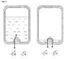
- FIG. 1 On the left side, an ink cartridge according to the prior art is in a filled state. Light falling from the bottom of the ink cartridge onto a cathode surface of the reflection prism shown impinges there at an angle of approximately 45 °. Since the ink cartridge is filled with liquid, there is no total reflection and most of the light is transmitted to the inside of the cartridge tank. In contrast, the near-empty cartridge status is shown on the right side. Here a two-time total reflection takes place and the light beam reaches the sensor. From the FIG. 1 it becomes clear that in this case an empty tank is displayed even though there is still ink in the tank. In addition, the prism occupies a significant proportion of the tank volume, which is no longer available for ink. Furthermore, such a component is difficult to produce with an injection molding process, since due to the massive prism, the cooling behavior leads to significant deformations.
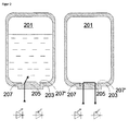
- FIG. 2 shows on the left side the cross section of an inventive ink cartridge 201 according to a first embodiment with embedded in the cartridge bottom 203 trapezoidal body 205. It can clearly be seen that the reflection point is placed in the plane which is formed by the cartridge bottom. This is made possible in the present embodiment by indentations 207, 207 'in the cartridge bottom, since now the trapezoidal body 205 is at the height of the trapezoidal bottom. In this way, on the one hand, it is ensured that the total reflection only takes place when the tank is actually empty. On the other hand, it is thus achieved that there are no significant volume losses in the cartridge tank. In addition, the trapezoidal body 205 used here has much less mass than the triangular prism known from the prior art. On the right side, the same cartridge is shown in an empty state. Here it becomes clear that only when almost no ink is left in the tank, the empty state is displayed.
- a body with a curved surface can also be used. This can be, for example, a half cylinder or a hemisphere. But also one Body showing in cross section the shape of a parabola can be used, then with the particular advantage that, as in the rectangular prism, the light beam at the same angle emerges from the body as it has entered, the ink tank should be empty. Important in all these geometries, however, is that the conditions for total reflection (full state: no, empty state: yes) are met.
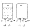
- FIG. 3 shows an inventive ink cartridge 301 according to a second embodiment.
- a total reflection body on the cartridge bottom 303 is present, for example in the form of a half hollow cylinder 305.
- the cylinder material is polypropylene (PP).
- PP polypropylene
- the geometry is chosen so that the angle of incidence on the essential interface is 57.5 °. Thus, with each total reflection, the beam direction is changed by 45 °.
- the beam direction is reversed and should exit from the cylinder jacket.
- the attentive expert will notice that there is now more than one level at which the light can enter the still-inked tank. In the example, there are two (three, because of the symmetry they are actually only two) planes. It should be noted, however, that due to the Fresnel reflections only a portion of the light enters the tank, although the total reflection condition is not met. However, this means that if the light sensor can also analyze luminous intensity differences, the discharge state can be displayed in more detail. First, the liquid surface reaches the upper level. Due to the lack of light now at these points, the light signal is stronger and the measurement of the light sensor can be transformed into a signal "cartridge almost empty" to the user.
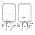
- FIG. 4 another embodiment of the present invention. Shown here is the cross section through an ink cartridge 401
- the cartridge bottom 403 remains unchanged plan and the question of whether there is still ink in the cartridge tank decides at an interface.
- the light beam entering a first extension 405 is totally reflected on a first surface 407 towards the bottom of the cartridge.
- the light beam exiting the bottom surface is absorbed in the ink.
- the light beam is further totally reflected on the bottom surface 409 and totally reflected on a second inclined surface 407 'of a second extension 405', so that the light beam can exit vertically.
- First extension 405, parts of the cartridge base 403 and second extension 405 'therefore form a kind of light guide
- the cartridge may be beneficial to provide the cartridge with a slanted bottom to allow for secure detection when the cartridge is empty.
- such an inclination would run into the image plane. It is therefore in the FIG. 4 not to be seen.
- the side walls of the light guide which are preferably parallel in the case of a flat bottom, must now be set at an angle to one another when the light source and light sensor of the detection device are in the same position relative to the longitudinal axis of the cartridge.
- there would be an undesirable deflection of the light beam which would be counteracted for example by offsetting the transmitter and receiver positions.
- the input and output surface of the light guide can be bevelled so that the light beam is deflected due to the refraction at this interface such that the side walls can still be performed in parallel.
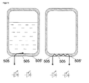
- FIG. 5 shows a further embodiment according to the present invention.
- the cartridge bottom 503 itself is designed as a light guide.
- a first diffraction grating 505 is provided on the cartridge bottom 503, which diffracts the light beam into the cartridge bottom.
- this diffraction grating 505 is arranged outside and formed as a surface structure.
- binary and / or symmetric surface gratings can be used here.
- sawtooth gratings are provided which effectively and asymmetrically divide the light beam into one Couple diffraction order.
- absorption grids or phase gratings are also possible.
- the light beam is incident on a second diffraction grating 505 '.
- the light beam uncouples in the original direction and falls on the light sensor.
- this only applies if there is no more ink in the cartridge tank. Otherwise, the light beam is absorbed by the ink as in the other embodiments.
- diffraction gratings can be produced very well by injection molding because of their dimensioning: these gratings have a grating period in the range of 10 ⁇ m to several hundred ⁇ m, the grating period defining the propagation direction of the diffraction order. With an optimal grid depth, a diffraction efficiency of a sawtooth grid can be optimized to almost 100%. If, as already described above, an obliquely positioned cartridge arc, the diffraction gratings can easily be rotated in their orientation in order to arrive at the desired optical path due to conical diffraction.
- the invention can be used in a so-called two-chamber cartridge.
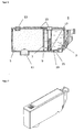
- FIG. 6 such a two-chamber cartridge 1 is shown schematically.
- the two-chamber cartridge 1 has a housing made of plastic, which is subdivided by a partition 7 into an ink chamber 3 and a storage chamber 5 in fluid communication with the ink chamber 3.
- a non-illustrated capillary ink storage is usually included, for example, a porous sponge or a nonwoven material in which the liquid ink is stored.
- the storage chamber 20 is in fluid communication with an ink discharge 11 formed on the underside of the housing, which is coupled to a supply port of the printer when the ink cartridge 1 is properly inserted into a cartridge receptacle of the printer so that ink from the ink cartridge 1 is supplied to a printhead as needed.
- the two-chamber cartridge also comprises, for example, a ventilation device 13 closed by a tear-open film, which is connected to at least one ventilation opening 15 via at least one channel, for example closed by a film, not shown here. This avoids that when the decrease Ink volume creates a negative pressure.
- a so-called bubble generator 17 which is connected via a second ventilation opening 15 with the ventilation device 13, and a gravity base 19 and the inventive light guide 21st
- the gravitational bottom 19 is formed substantially as a plane inclined plane. In this way, it is achieved that ink residues flow off in the direction of the storage chamber 5, thereby ensuring reliable draining and dewetting of the ink.
- the inventive light guide 21 is provided at the gravitational bottom 19 .
- the ink chamber 3 has little bottom surface, and thus filling level detection has only a small space available for arranging optical elements. In connection with such, often very narrow trained two-chamber cartridge 1, the provision of an inventive light guide is therefore particularly advantageous.
- such a two-chamber cartridge is usually designed to be very narrow.
- considerable ink tank volume can be saved, which is a particularly big advantage in narrow ink cartridges.
Landscapes
- Ink Jet (AREA)
Applications Claiming Priority (1)
| Application Number | Priority Date | Filing Date | Title |
|---|---|---|---|
| DE102009041650A DE102009041650A1 (de) | 2009-09-17 | 2009-09-17 | Tintenpatrone mit Elementen für Füllstandsdetektion |
Publications (2)
| Publication Number | Publication Date |
|---|---|
| EP2298559A2 true EP2298559A2 (fr) | 2011-03-23 |
| EP2298559A3 EP2298559A3 (fr) | 2011-09-21 |
Family
ID=42829525
Family Applications (1)
| Application Number | Title | Priority Date | Filing Date |
|---|---|---|---|
| EP10008512A Withdrawn EP2298559A3 (fr) | 2009-09-17 | 2010-08-16 | Cartouche d'encre dotée d'éléments pour la détection du niveau de remplissage |
Country Status (2)
| Country | Link |
|---|---|
| EP (1) | EP2298559A3 (fr) |
| DE (1) | DE102009041650A1 (fr) |
Families Citing this family (2)
| Publication number | Priority date | Publication date | Assignee | Title |
|---|---|---|---|---|
| DE102017214006A1 (de) * | 2017-08-10 | 2019-02-14 | BSH Hausgeräte GmbH | Heißgetränkezubereitungsvorrichtung |
| CN220024797U (zh) * | 2023-05-04 | 2023-11-17 | 浙江比依电器股份有限公司 | 一种光电液位式感应的环岛型双箱结构 |
Citations (2)
| Publication number | Priority date | Publication date | Assignee | Title |
|---|---|---|---|---|
| EP0955169A2 (fr) | 1993-05-26 | 1999-11-10 | Canon Kabushiki Kaisha | Appareil d'enregistrement à jet d'encre |
| EP0860284B1 (fr) | 1997-02-19 | 2000-12-06 | Canon Kabushiki Kaisha | Système détection de niveau de liquide, dispositif d'impression à jet de liquide et récipient de liquide |
Family Cites Families (14)
| Publication number | Priority date | Publication date | Assignee | Title |
|---|---|---|---|---|
| JP3167789B2 (ja) * | 1992-06-03 | 2001-05-21 | キヤノン株式会社 | インクジェット記録装置及びインク残量低下検知方法 |
| JPH0929989A (ja) * | 1995-07-14 | 1997-02-04 | Canon Inc | インク有無検出装置、インクタンク、キット、記録ユニット、記録装置、および情報処理システム |
| US6454400B1 (en) * | 1998-09-01 | 2002-09-24 | Canon Kabushiki Kaisha | Liquid container, cartridge including liquid container, printing apparatus using cartridge and liquid discharge printing apparatus |
| JP2001063098A (ja) * | 1999-04-27 | 2001-03-13 | Canon Inc | 液体収納容器、該液体収納容器に用いられる弁機構および液体供給容器 |
| US6520612B1 (en) * | 2001-03-26 | 2003-02-18 | Xerox Corporation | Sensing system for detecting presence of an ink container |
| US6619776B2 (en) * | 2001-03-30 | 2003-09-16 | Brother Kogyo Kabushiki Kaisha | Image forming device capable of detecting existence of ink and ink cartridge with high accuracy |
| JP4018422B2 (ja) * | 2002-03-29 | 2007-12-05 | キヤノン株式会社 | 液体収納容器、および液体収納容器の識別方法 |
| KR100452851B1 (ko) * | 2002-10-23 | 2004-10-14 | 삼성전자주식회사 | 적정 부압이 유지되는 잉크 카트리지 |
| US7040728B2 (en) * | 2003-06-06 | 2006-05-09 | Fuji Xerox Co., Ltd. | Geometry for a dual level fluid quantity sensing refillable fluid container |
| JP4519070B2 (ja) * | 2003-10-16 | 2010-08-04 | 理想科学工業株式会社 | インク容器 |
| JP4576871B2 (ja) * | 2004-04-21 | 2010-11-10 | セイコーエプソン株式会社 | 収容物検出装置、容器、及びインクジェットプリンタ |
| JP4101230B2 (ja) * | 2004-12-08 | 2008-06-18 | キヤノン株式会社 | 液体貯蔵容器および記録装置 |
| US20100271443A1 (en) * | 2007-12-06 | 2010-10-28 | Lori Nelson | Ink cartridge having a prism |
| JP5274120B2 (ja) * | 2008-06-20 | 2013-08-28 | キヤノン株式会社 | インクタンク、記録装置、インク残量検知システムおよびインク残量検知方法 |
-
2009
- 2009-09-17 DE DE102009041650A patent/DE102009041650A1/de not_active Withdrawn
-
2010
- 2010-08-16 EP EP10008512A patent/EP2298559A3/fr not_active Withdrawn
Patent Citations (2)
| Publication number | Priority date | Publication date | Assignee | Title |
|---|---|---|---|---|
| EP0955169A2 (fr) | 1993-05-26 | 1999-11-10 | Canon Kabushiki Kaisha | Appareil d'enregistrement à jet d'encre |
| EP0860284B1 (fr) | 1997-02-19 | 2000-12-06 | Canon Kabushiki Kaisha | Système détection de niveau de liquide, dispositif d'impression à jet de liquide et récipient de liquide |
Also Published As
| Publication number | Publication date |
|---|---|
| EP2298559A3 (fr) | 2011-09-21 |
| DE102009041650A1 (de) | 2011-03-24 |
Similar Documents
| Publication | Publication Date | Title |
|---|---|---|
| EP1147902B1 (fr) | Méthode pour détecter le niveau d'un liquide dans un réservoir | |
| DE3923007C2 (fr) | ||
| EP2102012B1 (fr) | Cartouche d'encre pour imprimante à jet d'encre | |
| DE112005002589T5 (de) | Flüssigkeitsspeicherbehälter und Tintenstrahlaufzeichnungsgerät | |
| DE3712699C2 (fr) | ||
| EP2298559A2 (fr) | Cartouche d'encre dotée d'éléments pour la détection du niveau de remplissage | |
| DE112014002837B4 (de) | Fahrzeuganzeigevorrichtung | |
| DE102009000529A1 (de) | Mikrofluidischer Chip mit Druckmesseinrichtung | |
| EP2872402A1 (fr) | Dispositif de remplissage de récipients | |
| DE19519417A1 (de) | Lenticulare optische Einrichtung | |
| EP3653304B1 (fr) | Récipient d'échantillon | |
| DE10039765A1 (de) | Vorrichtung zur Bestimmung der Füllhöhe eines Füllmediums in einem Tank | |
| DE102019212305A1 (de) | Verfahren zur Bestimmung eines Grads einer Verunreinigung des Fluids, insbesondere einer Flüssigkeit, in einem Behälter | |
| DE2534057A1 (de) | Vorrichtung zur fuellstandsanzeige und -ueberwachung | |
| AT9783U1 (de) | Verfahren und vorrichtung zur optischen messung von zustandsgrössen und füllstand in einem behälter für verflüssigte gase | |
| EP2686664A1 (fr) | Détection de milieux optiques plans en au moins deux couches à séparation optique | |
| EP2483080B1 (fr) | Cartouche d'encre pour imprimante à jet d'encre | |
| EP2425973B1 (fr) | Cartouche d'encre et imprimante à jet d'encre pour la réception d'une telle cartouche | |
| DE202009007358U1 (de) | Tintenkartusche | |
| DE3539308C2 (fr) | ||
| EP2641742A2 (fr) | Récipient collecteur de liquide, en particulier cartouche d'encre, pour imprimante à jet d'encre | |
| EP2352648A1 (fr) | Cartouche d'encre pour imprimante à jet d'encre | |
| DE19604255C2 (de) | Vorrichtung zur optischen Erfassung beschleunigungs- und/oder neigungsbedingter Bewegungen eines Körpers in einem Medium | |
| WO2011035935A1 (fr) | Cartouche d'encre pour imprimante à jet d'encre | |
| DE102014224328A1 (de) | Flüssigkeitsverbrauchsgerät |
Legal Events
| Date | Code | Title | Description |
|---|---|---|---|
| PUAI | Public reference made under article 153(3) epc to a published international application that has entered the european phase |
Free format text: ORIGINAL CODE: 0009012 |
|
| 17P | Request for examination filed |
Effective date: 20100816 |
|
| AK | Designated contracting states |
Kind code of ref document: A2 Designated state(s): AL AT BE BG CH CY CZ DE DK EE ES FI FR GB GR HR HU IE IS IT LI LT LU LV MC MK MT NL NO PL PT RO SE SI SK SM TR |
|
| AX | Request for extension of the european patent |
Extension state: BA ME RS |
|
| PUAL | Search report despatched |
Free format text: ORIGINAL CODE: 0009013 |
|
| AK | Designated contracting states |
Kind code of ref document: A3 Designated state(s): AL AT BE BG CH CY CZ DE DK EE ES FI FR GB GR HR HU IE IS IT LI LT LU LV MC MK MT NL NO PL PT RO SE SI SK SM TR |
|
| AX | Request for extension of the european patent |
Extension state: BA ME RS |
|
| RIC1 | Information provided on ipc code assigned before grant |
Ipc: B41J 2/175 20060101AFI20110816BHEP |
|
| RAP1 | Party data changed (applicant data changed or rights of an application transferred) |
Owner name: PELIKAN HARDCOPY PRODUCTION AG |
|
| STAA | Information on the status of an ep patent application or granted ep patent |
Free format text: STATUS: THE APPLICATION HAS BEEN WITHDRAWN |
|
| 18W | Application withdrawn |
Effective date: 20160822 |