EP2299330A2 - Dynamisches Meidendicke- und Biegungsabtastsystem - Google Patents
Dynamisches Meidendicke- und Biegungsabtastsystem Download PDFInfo
- Publication number
- EP2299330A2 EP2299330A2 EP10176309A EP10176309A EP2299330A2 EP 2299330 A2 EP2299330 A2 EP 2299330A2 EP 10176309 A EP10176309 A EP 10176309A EP 10176309 A EP10176309 A EP 10176309A EP 2299330 A2 EP2299330 A2 EP 2299330A2
- Authority
- EP
- European Patent Office
- Prior art keywords
- nip
- media sheet
- media
- sensor
- opposing rollers
- Prior art date
- Legal status (The legal status is an assumption and is not a legal conclusion. Google has not performed a legal analysis and makes no representation as to the accuracy of the status listed.)
- Withdrawn
Links
- 238000000034 method Methods 0.000 claims abstract description 43
- 238000012545 processing Methods 0.000 claims abstract description 15
- 238000007639 printing Methods 0.000 claims description 20
- 238000007641 inkjet printing Methods 0.000 claims description 6
- 230000032258 transport Effects 0.000 claims description 4
- 238000006073 displacement reaction Methods 0.000 description 13
- 238000005259 measurement Methods 0.000 description 5
- 238000010586 diagram Methods 0.000 description 4
- 230000008569 process Effects 0.000 description 4
- 230000006870 function Effects 0.000 description 2
- 230000015654 memory Effects 0.000 description 2
- 101100225582 Neurospora crassa (strain ATCC 24698 / 74-OR23-1A / CBS 708.71 / DSM 1257 / FGSC 987) nip-1 gene Proteins 0.000 description 1
- 230000003044 adaptive effect Effects 0.000 description 1
- 238000013459 approach Methods 0.000 description 1
- 230000006399 behavior Effects 0.000 description 1
- 230000007423 decrease Effects 0.000 description 1
- 230000000694 effects Effects 0.000 description 1
- 230000007613 environmental effect Effects 0.000 description 1
- 230000005484 gravity Effects 0.000 description 1
- 239000000463 material Substances 0.000 description 1
- 238000012986 modification Methods 0.000 description 1
- 230000004048 modification Effects 0.000 description 1
- 230000002093 peripheral effect Effects 0.000 description 1
- 239000007787 solid Substances 0.000 description 1
- 238000012360 testing method Methods 0.000 description 1
Images


Classifications
-
- G—PHYSICS
- G03—PHOTOGRAPHY; CINEMATOGRAPHY; ANALOGOUS TECHNIQUES USING WAVES OTHER THAN OPTICAL WAVES; ELECTROGRAPHY; HOLOGRAPHY
- G03G—ELECTROGRAPHY; ELECTROPHOTOGRAPHY; MAGNETOGRAPHY
- G03G15/00—Apparatus for electrographic processes using a charge pattern
- G03G15/50—Machine control of apparatus for electrographic processes using a charge pattern, e.g. regulating differents parts of the machine, multimode copiers, microprocessor control
- G03G15/5029—Machine control of apparatus for electrographic processes using a charge pattern, e.g. regulating differents parts of the machine, multimode copiers, microprocessor control by measuring the copy material characteristics, e.g. weight, thickness
-
- G—PHYSICS
- G03—PHOTOGRAPHY; CINEMATOGRAPHY; ANALOGOUS TECHNIQUES USING WAVES OTHER THAN OPTICAL WAVES; ELECTROGRAPHY; HOLOGRAPHY
- G03G—ELECTROGRAPHY; ELECTROPHOTOGRAPHY; MAGNETOGRAPHY
- G03G15/00—Apparatus for electrographic processes using a charge pattern
- G03G15/65—Apparatus which relate to the handling of copy material
- G03G15/6555—Handling of sheet copy material taking place in a specific part of the copy material feeding path
- G03G15/6558—Feeding path after the copy sheet preparation and up to the transfer point, e.g. registering; Deskewing; Correct timing of sheet feeding to the transfer point
- G03G15/6561—Feeding path after the copy sheet preparation and up to the transfer point, e.g. registering; Deskewing; Correct timing of sheet feeding to the transfer point for sheet registration
-
- G—PHYSICS
- G03—PHOTOGRAPHY; CINEMATOGRAPHY; ANALOGOUS TECHNIQUES USING WAVES OTHER THAN OPTICAL WAVES; ELECTROGRAPHY; HOLOGRAPHY
- G03G—ELECTROGRAPHY; ELECTROPHOTOGRAPHY; MAGNETOGRAPHY
- G03G2215/00—Apparatus for electrophotographic processes
- G03G2215/00362—Apparatus for electrophotographic processes relating to the copy medium handling
- G03G2215/00535—Stable handling of copy medium
- G03G2215/00548—Jam, error detection, e.g. double feeding
-
- G—PHYSICS
- G03—PHOTOGRAPHY; CINEMATOGRAPHY; ANALOGOUS TECHNIQUES USING WAVES OTHER THAN OPTICAL WAVES; ELECTROGRAPHY; HOLOGRAPHY
- G03G—ELECTROGRAPHY; ELECTROPHOTOGRAPHY; MAGNETOGRAPHY
- G03G2215/00—Apparatus for electrophotographic processes
- G03G2215/00362—Apparatus for electrophotographic processes relating to the copy medium handling
- G03G2215/00535—Stable handling of copy medium
- G03G2215/00717—Detection of physical properties
- G03G2215/00721—Detection of physical properties of sheet position
Definitions
- Embodiments herein generally relate to printing methods and devices and more particularly relate to systems that accommodate media curling and different media thicknesses.
- Printing systems such as electro-photographic, inkjet, and ultra-violet (UV) curable systems, have higher quality results if the thickness and curl of the media being used is known and adjusted for.
- Current systems rely on users to input the type of paper being used via the "user interface”. This approach only tells the printing apparatus the approximate weight of the paper and not its actual thickness and is subject to wrong input.
- Conventional decurling adjustments are also based on a combination of user inputs and some sensor data such as temperature, humidity, double sided printing mode, etc.
- Current systems do not measure actual curl, but estimate what the curl is likely to be based on setup parameters.
- some machines provide an additional manual adjustment that usually cannot be made on the fly. Complicating the problem for these systems is the uncertain nature of paper in its curl behavior.
- U.S. Patent 5,519,481 (incorporated herein by reference) describes an adaptive decurler for selective decurling localized image areas, where a segmented decurling device forms a drive nip with an elastically deformable surfaced roll.
- a plurality of sensors are provided to determine the basis weight of the copy sheet, the density of the image being transferred to the copy sheet and fused thereon, the relative humidity of the machine environment, the process speed of the print engine, and any other relevant parameters. Signals indicative of these parameters are generated and sent to the machine controller which processes these signals to determine the degree of curl expected in a sheet.
- the decurler segment Based on the degree of curl for each sheet section corresponding to a decurler segment, the decurler segment is actuated to a setting which should provide the proper amount of mechanical decurling force. Each segment is activated only for the duration deemed necessary to decurl the imaged sheet portion corresponding thereto.
- the present embodiments comprise a method and a system of rollers, sensors, and processors used to determine actual paper curl and paper thickness. Once the actual paper curl and thickness is determined, such information is used for adjusting printing parameters.
- the system uses rollers to hold the paper precisely at a fixed distance while a displacement sensor measures edge curl followed by paper thickness. The resulting data is then processed to predict the overall curl of the paper.
- the system uses the thickness data to more accurately determine curl based on methodologies and/or look up tables. Also, the setup can involve a calibration mode to accurately measure paper thickness.
- embodiments herein provide an apparatus that has a media path that transports a media sheet; a first nip (comprising opposing rollers) that moves the media sheet in a processing direction; a second nip (also comprising opposing rollers) that is positioned within the media path to receive the media sheet from the first nip; and a third nip (again comprising opposing rollers) that is positioned within the media path to receive the media sheet from the second nip.
- a sensor is positioned between the second nip and the third nip. The sensor senses the position of the media sheet relative to the sensor.
- a processor that is operatively connected to the sensor automatically calculates the amount of curl (up or down) the media sheet contains based on the difference between a predetermined position (determined using a calibration sheet) and the position of the leading edge of the media sheet (relative to the sensor) as the leading edge of the media sheet passes between the second nip and the third nip.
- the processor can automatically calculate the thickness of the media sheet based on the difference between the predetermined position and the position of the media sheet (relative to the sensor) as the media sheet passes between the second nip and the third nip.
- the opposing rollers within the first nip, the second nip, and the third nip each comprise a fixed-position roller and a floating roller.
- the floating roller is positioned to contact a first side (the top side) of the media sheet and the sensor is also positioned to sense the first side of the media sheet.
- the opposing rollers of the second nip rotate faster than the opposing rollers of the first nip, and the opposing rollers of the third nip rotate faster than the opposing rollers of the second nip to keep the media sheet taunt during the curl and thickness measurements.
- the apparatus can also include a decurler positioned within the media path.
- the processor automatically alters settings of the decurler based on the actual amount of curl the media sheet contains.
- the apparatus can contain a marking engine positioned within the media path. Again, the processor automatically alters settings of the marking engine based on the amount of curl the media sheet contains and the thickness of the media sheet.
- the marking engine can comprise any type of marking engine, such as an electro-photographic printing engine, an inkjet printing engine, an ultra-violet curable printing engine, etc.
- the method moves the media sheet in the processing direction of the media path from the first nip to the second nip and moves the media sheet in the processing direction of the media path from the second nip to the third nip.
- the method senses, using the sensor positioned between the second nip and the third nip, the position of the media sheet relative to the sensor.
- the method automatically calculates the amount of curl the media sheet contains based on the difference between the predetermined position and the position of the leading edge of the media sheet (relative to the sensor) as the leading edge of the media sheet passes between the second nip and the third nip, using the processor.
- the method automatically calculates the thickness of the media sheet based on the difference between the predetermined position and the position of the media sheet (relative to the sensor) as the media sheet passes between the second nip and the third nip, using the processor.
- the method can also automatically alter the settings of the decurler positioned within the media path based on the amount of the curl the media sheet contains using the processor. Also, the method can automatically alter settings of the marking engine positioned within the media path based on the amount of curl the media sheet contains and the thickness of the media sheet using the processor. In one embodiment of the method according to claim 11, the method further comprises automatically altering setting of a marking engine positioned within said media path based on said amount of curl said media sheet contains using said processor, said marking engine comprising one of an electro-photographic printing engine, an inkjet printing engine, and an ultra-violet curable printing engine.
- said opposing rollers within said first nip, said second nip, and said third nip each comprises a fixed-position roller and a floating roller, wherein said floating roller is positioned to contact a first side of said media sheet and said sensor is positioned to sense said first side of said media sheet.
- the method further comprises rotating said opposing rollers of said second nip faster than said opposing rollers of said first nip, and rotating said opposing rollers of said third nip faster than said opposing rollers of said second nip.
- the method further comprises automatically altering settings of a decurler positioned within said media path based on said amount of said curl said media sheet contains using said processor.
- the method further comprises automatically altering setting of a marking engine positioned within said media path based on said amount of curl said media sheet contains and said thickness of said media sheet using said processor, said marking engine comprising one of an electro-photographic printing engine, an inkjet printing engine, and an ultra-violet curable printing engine.
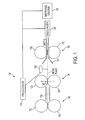
- Figure 1 is a side-view schematic diagram of a device according to embodiments herein;
- Figure 2 is a side-view schematic diagram of a device according to embodiments herein;
- Figure 3 is a schematic diagram illustrating hanging curl measurement
- Figure 4 is a chart illustrating the relationship between displacement and curl radius according to embodiments herein;
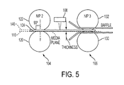
- Figure 5 is a side-view schematic diagram of a device according to embodiments herein.
- Figure 6 is a flowchart illustrating method embodiments herein.
- the embodiments herein provide a media thickness curl sensing system that comprises a series of three nips used to control a sheet of paper in a precise way so that the curl and thickness attributes can be measured.
- a displacement sensor that is used to measure fly height and paper thickness.
- one apparatus has a media path 116 that transports a media sheet 124; a first nip 102 (comprising opposing rollers 110, 112) that moves the media sheet 124 in a processing direction; a second nip 104 (also comprising opposing rollers 120, 122) that is positioned within the media path 116 to receive the media sheet 124 from the first nip 102; and a third nip 130 (again comprising opposing rollers) that is positioned within the media path 116 to receive the media sheet 124 from the second nip 104.
- a sensor 108 is positioned between the second nip 104 and the third nip 130.
- the sensor can be any type of readily available sensor, such as one that is light based (laser), sound based (sonar), air pressure based, etc.
- the sensor 108 senses the position of the media sheet 124 relative to the sensor 108.
- the apparatus can also include a decurler 136 positioned within the media path 116.
- the processor 118 automatically alters settings of the decurler 136 based on the amount of curl the media sheet 124 contains.
- the apparatus can contain a marking engine 138 positioned within the media path 116. Again, the processor 118 automatically alters setting of the marking engine 138 based on the amount of curl the media sheet 124 contains.
- the marking engine 138 can comprise any type of marking engine 138, such as an electro-photographic printing engine, an inkjet printing engine, an ultra-violet curable printing engine, etc.
- the media sheet 124 first enters nip 1 (102) then is driven to nip 2 (104) which is overdriven slightly faster than nip one 102.
- Over-driving the media sheet 124 in combination with nip 2 (104) being a set of two like rolls (both soft or both hard) helps to eliminate any bias of nip 2 (104) from driving the media sheet 124 up or down.
- nip two (104) drives the media sheet 124 out of its nip in plane with the media plane 116 formed by nips one and two.
- the media sheet 124 is held very close to 90° from the centerline 116 of nip 2 (104) so that its entry angle does not influence its exit angle.
- the media sheet 124 on exiting nip 2 (104) is free to curl up, curl down or exit straight out of the nip to be measured by the displacement sensor 108.
- the media sheet 124 curl (fly height) is read very close to nip two 104 (e.g., 10 mm, 20 mm, 30 mm, etc., from the second nip 104).
- the processor 118 (that is operatively connected to the sensor 108) automatically calculates the amount of curl the media sheet 124 contains based on the difference between a predetermined position (which could be the centerline of the media path 116) and the position of the leading edge of the media sheet 124 (relative to the sensor 108) as the leading edge of the media sheet 124 passes between the second nip 104 and the third nip 130.
- the position of the leading edge of the media 124 is shown as item 144 in Figure 2 . Therefore, the processor 118 calculates the curl distance as the difference between 116 and 144. From this distance the curl radius and sheet curl can be determined using lookup charts or methodologies, as discussed below.
- the systems and methods disclosed herein determine overall or uniform curl on media as can be seen in the hanging radius curl method of determining curl, see Figure 3 .
- media is fit to the circumference or curvature of a circle (item 202) with its curl being defined as the radius or 1/radius using a predetermined lookup chart 200. Because the curl is even, the angle formed by any line tangent to the media sheet 124 will be the same for any point about the curvature of the media sheet 124.
- measuring the height of the media sheet 124 just as the media sheet 124 exits nip 2 (104) should be the same angle that would be seen further into the sheet if gravity were not a factor. So by measuring the height of the media sheet 124 immediately exiting nip 2 (104) the hanging radius curl can be determined.
- the media sheet 124 close to the second nip 104 there are other advantages of measuring the media sheet 124 close to the second nip 104. For example, by doing so the media sheet 124 will have less distance to curl up or down and its displacement height will be less, so the displacement sensor 108 needed can be of a smaller displacement range (which lowers cost). Also, by measuring the media sheet 124 close to the second nip 104, the media cannot curl up or down excessively thereby getting out of control and possibly folding over on itself when it enters any downstream baffles 114. Note that baffles 114 have a wide opening that narrows as the baffle reaches the third nip 106 to allow curled sheets to be properly fed to the third nip 106.
- Figure 4 is a chart showing curl data taken from a laser displacement sensor 108.
- a coated 120gsm media was fed through a nip of two solid 20 mm diameter rolls and readings were taken 18mm from the center of the second nip 104.
- the data show is in pairs, that is, each sheet of media sheet 124 was fed twice, once in the up and once in the down curl position.
- the test shows that as the media sheet 124 curl decreases so does the tip fly height.
- tip fly height and media sheet caliper thickness are very close together for less curled media sheet in the 400mm radius curl area.
- the caliper thickness of the media sheet 124 was 0.10mm.
- the processor 118 can automatically calculate the thickness of the media sheet 124 based on the difference between the predetermined position 116 and the position of the media sheet 146 (relative to the sensor 108) as the media sheet 124 passes between the second nip 104 and the third nip 130. Therefore, as shown in Figure 5 , if the "predetermined position" is established as the portion of of the media path 116 where the bottom of the media sheet lies, the media sheet thickness would be the difference between items 116 and 146. If the "predetermined position" is the centerline of the media path 116, the media sheet thickness would be twice the difference between items 116 and 146.
- the media thickness measurement is accomplished with the same displacement sensor 108, but with the media sheet 124 stretched tight into nip 3 (106) as opposed to allowing the leading edge of the media to curl up or down, as was shown in Figure 2 . Again the downstream nip 106 is slightly over-driven to take up any slack and ensure that the media sheet 124 is flat between the second nip 104 and the third nip 106.
- a calibration procedure can occur, whereby a known thickness media sheet 124 is run and measured for media thickness by the displacement sensor 108 as in Figure 5 . The resulting values would then be compared to known values and the sensor 108 would be calibrated to the known value. This process establishes the "predetermined position" that is mentioned above.
- the bottom three rollers 110, 120, 130 are fixed (these rollers can rotate, but their axels do not move relative to the media path 116). Therefore, the top rollers 112, 122, 132, can rotate and move up and down relative to the media path 116 to accommodate different media thicknesses. This provides an unmovable reference plane (e.g., 116) with respect to media sheet 124 to allow the media thickness and curl measurements to be consistent. Therefore, the opposing rollers within the first nip 102, the second nip 104, and the third nip 130 each comprise a fixed-position roller and a floating roller.
- the floating roller is positioned to contact a first side (the top side) of the media sheet 124 and the sensor 108 is also positioned to sense the first side of the media sheet 124.
- the opposing rollers 120, 122 of the second nip 104 rotate faster than the opposing rollers 110, 112 of the first nip 102, and the opposing rollers 130, 132 of the third nip 130 rotate faster than the opposing rollers of the second nip 104 to keep the media sheet 124 taunt during the curl and thickness measurements.
- the method moves the media sheet 124 in the processing direction of the media path 116 from the first nip 102 to the second nip 104 and moves the media sheet 124 in the processing direction of the media path 116 from the second nip 104 to the third nip 130.
- the method senses, using the sensor 108 positioned between the second nip 104 and the third nip 130, the position of the media sheet 124 relative to the sensor 108.
- the method automatically calculates the amount of curl the media sheet 124 contains based on the difference between the predetermined position and the position of the leading edge of the media sheet 124 (relative to the sensor 108) as the leading edge of the media sheet 124 passes between the second nip 104 and the third nip 130, using the processor 118. Further, the method automatically calculates the thickness of the media sheet 124 based on the difference between the predetermined position and the position of the media sheet 124 (relative to the sensor 108) as the media sheet 124 passes between the second nip 104 and the third nip 130, using the processor 118 in item 606.
- the method can also automatically alter the settings of the decurler 136 positioned within the media path 116 based on the amount of the curl the media sheet 124 contains using the processor 118. Also, the method can automatically alter settings of the marking engine 138 positioned within the media path 116 based on the amount of curl the media sheet 124 contains and the thickness of the media sheet 124 using the processor 118 in item 610.
- the embodiments herein use a displacement sensor to measure the amount of curl of media exiting from a controlled nip and can use the same displacement sensor to measure the media sheet thickness in a controlled nip for more accurate results.
- the embodiments herein use actual measured properties of media to determine curl which is dynamic and more accurate that projections based on environmental conditions and user input.
- the embodiments herein use actual measured thickness to determine media weight which provides greater accuracy and less fallibility when compared to user input.
- Computerized devices that include chip-based central processing units (CPU's), input/output devices (including graphic user interfaces (GUI), memories, comparators, processors, etc. are well-known and readily available devices produced by manufacturers such as Dell Computers, Round Rock TX, USA and Apple Computer Co., Cupertino CA, USA.
- Such computerized devices commonly include input/output devices, power supplies, processors, electronic storage memories, wiring, etc., the details of which are omitted herefrom to allow the reader to focus on the salient aspects of the embodiments described herein.
- scanners and other similar peripheral equipment are available from Xerox Corporation, Norwalk, CT, USA and the details of such devices are not discussed herein for purposes of brevity and reader focus.
- printer or printing device encompasses any apparatus, such as a digital copier, bookmaking machine, facsimile machine, multifunction machine, etc., which performs a print outputting function for any purpose.
- the details of printers, printing engines, etc. are well-known by those ordinarily skilled in the art and are discussed in, for example, U.S. Patent 6,032,004 , the complete disclosure of which is fully incorporated herein by reference.
- the embodiments herein can encompass embodiments that print in color, monochrome, or handle color or monochrome image data. All foregoing embodiments are specifically applicable to electrostatographic and/or xerographic machines and/or processes.
Landscapes
- Physics & Mathematics (AREA)
- General Physics & Mathematics (AREA)
- Engineering & Computer Science (AREA)
- Microelectronics & Electronic Packaging (AREA)
- Controlling Sheets Or Webs (AREA)
- Separation, Sorting, Adjustment, Or Bending Of Sheets To Be Conveyed (AREA)
- Ink Jet (AREA)
Applications Claiming Priority (1)
| Application Number | Priority Date | Filing Date | Title |
|---|---|---|---|
| US12/560,006 US20110064424A1 (en) | 2009-09-15 | 2009-09-15 | Dynamic media thickness, curl sensing system |
Publications (2)
| Publication Number | Publication Date |
|---|---|
| EP2299330A2 true EP2299330A2 (de) | 2011-03-23 |
| EP2299330A3 EP2299330A3 (de) | 2012-03-14 |
Family
ID=43425833
Family Applications (1)
| Application Number | Title | Priority Date | Filing Date |
|---|---|---|---|
| EP10176309A Withdrawn EP2299330A3 (de) | 2009-09-15 | 2010-09-13 | Dynamisches Meidendicke- und Biegungsabtastsystem |
Country Status (3)
| Country | Link |
|---|---|
| US (1) | US20110064424A1 (de) |
| EP (1) | EP2299330A3 (de) |
| JP (1) | JP2011063441A (de) |
Families Citing this family (5)
| Publication number | Priority date | Publication date | Assignee | Title |
|---|---|---|---|---|
| CN103444138B (zh) | 2011-03-23 | 2016-03-30 | 日本电气株式会社 | 通信控制系统、交换节点以及通信控制方法 |
| JP6094158B2 (ja) * | 2012-01-31 | 2017-03-15 | 株式会社リコー | 画像形成装置およびカール矯正方法 |
| US9013758B1 (en) * | 2013-10-18 | 2015-04-21 | Foxlink Image Technology Co., Ltd. | Scanned image calibration device and method thereof for adjusting a scan frequency |
| US10082476B2 (en) * | 2013-12-20 | 2018-09-25 | Ncr Corporation | Sensing of media items |
| US9604478B1 (en) | 2016-06-16 | 2017-03-28 | Xerox Corporation | Print media beam strength sensor |
Citations (2)
| Publication number | Priority date | Publication date | Assignee | Title |
|---|---|---|---|---|
| US5519481A (en) | 1994-10-11 | 1996-05-21 | Xerox Corporation | Adaptive decurler for selective decurling of localized image areas |
| US6032004A (en) | 1998-01-08 | 2000-02-29 | Xerox Corporation | Integral safety interlock latch mechanism |
Family Cites Families (20)
| Publication number | Priority date | Publication date | Assignee | Title |
|---|---|---|---|---|
| US4475896A (en) * | 1981-12-02 | 1984-10-09 | Xerox Corporation | Curling/decurling method and mechanism |
| US4505695A (en) * | 1983-04-18 | 1985-03-19 | Xerox Corporation | Sheet decurling mechanism |
| US4926358A (en) * | 1987-05-20 | 1990-05-15 | Ricoh Company, Ltd. | System for controlling curls of a paper |
| JP2579636B2 (ja) * | 1987-05-20 | 1997-02-05 | 株式会社リコー | 複写装置 |
| JPH0616282A (ja) * | 1992-07-01 | 1994-01-25 | Fuji Xerox Co Ltd | 厚さ検出装置 |
| US5934140A (en) * | 1996-06-19 | 1999-08-10 | Xerox Corporation | Paper property sensing system |
| JPH10123781A (ja) * | 1996-10-23 | 1998-05-15 | Mita Ind Co Ltd | 画像形成装置 |
| KR19990000507A (ko) * | 1997-06-05 | 1999-01-15 | 손욱 | 발광 효율이 개선된 새로운 저전압용 형광체 및 그의 제조 방법 |
| JP2000229758A (ja) * | 1999-02-09 | 2000-08-22 | Fuji Xerox Co Ltd | カール補正装置、画像形成装置 |
| JP3762566B2 (ja) * | 1999-04-09 | 2006-04-05 | キヤノン電子株式会社 | シート材搬送装置及び画像読取装置及び画像形成装置 |
| JP3424095B2 (ja) * | 2000-08-02 | 2003-07-07 | ミネベア株式会社 | 磁気光学体及びこの磁気光学体を用いた光アイソレータ |
| US6684776B2 (en) * | 2001-02-23 | 2004-02-03 | Heidelberger Druckmaschinen Ag | Method and apparatus for determining slipping in a nip roller |
| US6668155B1 (en) * | 2002-07-23 | 2003-12-23 | Xerox Corporation | Lead edge paper curl sensor |
| US6881972B2 (en) * | 2002-11-04 | 2005-04-19 | Hewlett-Packard Development Company, L.P. | Media stiffness detection device and method therefor |
| US7545519B2 (en) * | 2006-07-20 | 2009-06-09 | Xerox Corporation | Lead edge sheet curl sensor |
| JP4842792B2 (ja) * | 2006-12-20 | 2011-12-21 | 株式会社リコー | 画像形成装置 |
| JP4991445B2 (ja) * | 2007-08-22 | 2012-08-01 | リコーエレメックス株式会社 | カール検出装置、カール検出方法、後処理装置、および画像形成装置 |
| JP4631914B2 (ja) * | 2008-01-23 | 2011-02-16 | コニカミノルタビジネステクノロジーズ株式会社 | 用紙処理装置 |
| JP4985434B2 (ja) * | 2008-01-29 | 2012-07-25 | Nkワークス株式会社 | デカール機構 |
| JP2010100391A (ja) * | 2008-10-23 | 2010-05-06 | Canon Inc | カール検出装置および記録装置 |
-
2009
- 2009-09-15 US US12/560,006 patent/US20110064424A1/en not_active Abandoned
-
2010
- 2010-08-27 JP JP2010190578A patent/JP2011063441A/ja active Pending
- 2010-09-13 EP EP10176309A patent/EP2299330A3/de not_active Withdrawn
Patent Citations (2)
| Publication number | Priority date | Publication date | Assignee | Title |
|---|---|---|---|---|
| US5519481A (en) | 1994-10-11 | 1996-05-21 | Xerox Corporation | Adaptive decurler for selective decurling of localized image areas |
| US6032004A (en) | 1998-01-08 | 2000-02-29 | Xerox Corporation | Integral safety interlock latch mechanism |
Also Published As
| Publication number | Publication date |
|---|---|
| US20110064424A1 (en) | 2011-03-17 |
| JP2011063441A (ja) | 2011-03-31 |
| EP2299330A3 (de) | 2012-03-14 |
Similar Documents
| Publication | Publication Date | Title |
|---|---|---|
| JP7136171B2 (ja) | パラメータ決定装置、画像形成装置、後処理装置、給紙装置、およびパラメータ決定方法 | |
| EP2299330A2 (de) | Dynamisches Meidendicke- und Biegungsabtastsystem | |
| US10029871B2 (en) | Image forming apparatus and setting method | |
| WO2009028731A1 (ja) | 画像形成装置 | |
| US20100329759A1 (en) | Sheet length measuring apparatus, image forming apparatus, and sheet length measuring method | |
| US9710202B2 (en) | Image forming apparatus having first sheet holding unit for which sheet type is registered and second sheet holding unit for which sheet type is not registered, method for controlling image forming apparatus, and storage medium | |
| US20110001996A1 (en) | Image forming apparatus and image forming method | |
| JP2006023288A (ja) | 記録材判別装置および方法 | |
| US10353324B2 (en) | Image forming apparatus and control method | |
| JP7559531B2 (ja) | 搬送装置、画像形成装置および画像形成システム | |
| EP2767872A2 (de) | Kräuselglättungsverfahren und Bilderzeugungsvorrichtung | |
| JP2023061933A (ja) | パラメータ決定装置、画像形成装置、後処理装置、給紙装置、決定モデルの作成方法、および制御プログラム | |
| JP6468862B2 (ja) | 画像形成装置 | |
| JP2023011123A (ja) | 画像形成装置、および制御プログラム | |
| US10042304B2 (en) | Sheet conveyance apparatus | |
| US11533408B2 (en) | Sheet conveyance device and image forming apparatus | |
| US9604478B1 (en) | Print media beam strength sensor | |
| US10166790B1 (en) | Dynamic print media weight determination system and method | |
| US9535355B2 (en) | Image forming apparatus | |
| US7903991B2 (en) | Method and apparatus for measuring nip width in an image production device | |
| JP2007206167A (ja) | 画像形成装置およびその制御方法 | |
| JP7834998B2 (ja) | 画像形成装置、画像形成システム、および制御プログラム | |
| JP5838495B2 (ja) | 測定装置及びそれを備えた画像形成装置 | |
| JP5721871B2 (ja) | シート搬送装置及び画像形成装置 | |
| US20130250279A1 (en) | Gloss Measuring Device and Image Forming Device Including Same |
Legal Events
| Date | Code | Title | Description |
|---|---|---|---|
| PUAI | Public reference made under article 153(3) epc to a published international application that has entered the european phase |
Free format text: ORIGINAL CODE: 0009012 |
|
| AK | Designated contracting states |
Kind code of ref document: A2 Designated state(s): AL AT BE BG CH CY CZ DE DK EE ES FI FR GB GR HR HU IE IS IT LI LT LU LV MC MK MT NL NO PL PT RO SE SI SK SM TR |
|
| AX | Request for extension of the european patent |
Extension state: BA ME RS |
|
| RIC1 | Information provided on ipc code assigned before grant |
Ipc: G03G 15/00 20060101AFI20111020BHEP |
|
| PUAL | Search report despatched |
Free format text: ORIGINAL CODE: 0009013 |
|
| AK | Designated contracting states |
Kind code of ref document: A3 Designated state(s): AL AT BE BG CH CY CZ DE DK EE ES FI FR GB GR HR HU IE IS IT LI LT LU LV MC MK MT NL NO PL PT RO SE SI SK SM TR |
|
| AX | Request for extension of the european patent |
Extension state: BA ME RS |
|
| RIC1 | Information provided on ipc code assigned before grant |
Ipc: G03G 15/00 20060101AFI20120207BHEP |
|
| 17P | Request for examination filed |
Effective date: 20120914 |
|
| STAA | Information on the status of an ep patent application or granted ep patent |
Free format text: STATUS: THE APPLICATION IS DEEMED TO BE WITHDRAWN |
|
| 18D | Application deemed to be withdrawn |
Effective date: 20160401 |