EP2301667B1 - Procédé de broyage basse pression - Google Patents
Procédé de broyage basse pression Download PDFInfo
- Publication number
- EP2301667B1 EP2301667B1 EP10174068.6A EP10174068A EP2301667B1 EP 2301667 B1 EP2301667 B1 EP 2301667B1 EP 10174068 A EP10174068 A EP 10174068A EP 2301667 B1 EP2301667 B1 EP 2301667B1
- Authority
- EP
- European Patent Office
- Prior art keywords
- grinding
- process according
- classifier
- classifying
- bar
- Prior art date
- Legal status (The legal status is an assumption and is not a legal conclusion. Google has not performed a legal analysis and makes no representation as to the accuracy of the status listed.)
- Active
Links
Images

Classifications
-
- B—PERFORMING OPERATIONS; TRANSPORTING
- B02—CRUSHING, PULVERISING, OR DISINTEGRATING; PREPARATORY TREATMENT OF GRAIN FOR MILLING
- B02C—CRUSHING, PULVERISING, OR DISINTEGRATING IN GENERAL; MILLING GRAIN
- B02C19/00—Other disintegrating devices or methods
- B02C19/06—Jet mills
-
- C—CHEMISTRY; METALLURGY
- C09—DYES; PAINTS; POLISHES; NATURAL RESINS; ADHESIVES; COMPOSITIONS NOT OTHERWISE PROVIDED FOR; APPLICATIONS OF MATERIALS NOT OTHERWISE PROVIDED FOR
- C09C—TREATMENT OF INORGANIC MATERIALS, OTHER THAN FIBROUS FILLERS, TO ENHANCE THEIR PIGMENTING OR FILLING PROPERTIES ; PREPARATION OF CARBON BLACK ; PREPARATION OF INORGANIC MATERIALS WHICH ARE NO SINGLE CHEMICAL COMPOUNDS AND WHICH ARE MAINLY USED AS PIGMENTS OR FILLERS
- C09C1/00—Treatment of specific inorganic materials other than fibrous fillers; Preparation of carbon black
- C09C1/28—Compounds of silicon
- C09C1/30—Silicic acid
- C09C1/3009—Physical treatment, e.g. grinding; treatment with ultrasonic vibrations
- C09C1/3018—Grinding
-
- C—CHEMISTRY; METALLURGY
- C09—DYES; PAINTS; POLISHES; NATURAL RESINS; ADHESIVES; COMPOSITIONS NOT OTHERWISE PROVIDED FOR; APPLICATIONS OF MATERIALS NOT OTHERWISE PROVIDED FOR
- C09C—TREATMENT OF INORGANIC MATERIALS, OTHER THAN FIBROUS FILLERS, TO ENHANCE THEIR PIGMENTING OR FILLING PROPERTIES ; PREPARATION OF CARBON BLACK ; PREPARATION OF INORGANIC MATERIALS WHICH ARE NO SINGLE CHEMICAL COMPOUNDS AND WHICH ARE MAINLY USED AS PIGMENTS OR FILLERS
- C09C1/00—Treatment of specific inorganic materials other than fibrous fillers; Preparation of carbon black
- C09C1/28—Compounds of silicon
- C09C1/30—Silicic acid
- C09C1/3072—Treatment with macro-molecular organic compounds
-
- C—CHEMISTRY; METALLURGY
- C09—DYES; PAINTS; POLISHES; NATURAL RESINS; ADHESIVES; COMPOSITIONS NOT OTHERWISE PROVIDED FOR; APPLICATIONS OF MATERIALS NOT OTHERWISE PROVIDED FOR
- C09C—TREATMENT OF INORGANIC MATERIALS, OTHER THAN FIBROUS FILLERS, TO ENHANCE THEIR PIGMENTING OR FILLING PROPERTIES ; PREPARATION OF CARBON BLACK ; PREPARATION OF INORGANIC MATERIALS WHICH ARE NO SINGLE CHEMICAL COMPOUNDS AND WHICH ARE MAINLY USED AS PIGMENTS OR FILLERS
- C09C1/00—Treatment of specific inorganic materials other than fibrous fillers; Preparation of carbon black
- C09C1/28—Compounds of silicon
- C09C1/30—Silicic acid
- C09C1/3081—Treatment with organo-silicon compounds
-
- C—CHEMISTRY; METALLURGY
- C09—DYES; PAINTS; POLISHES; NATURAL RESINS; ADHESIVES; COMPOSITIONS NOT OTHERWISE PROVIDED FOR; APPLICATIONS OF MATERIALS NOT OTHERWISE PROVIDED FOR
- C09C—TREATMENT OF INORGANIC MATERIALS, OTHER THAN FIBROUS FILLERS, TO ENHANCE THEIR PIGMENTING OR FILLING PROPERTIES ; PREPARATION OF CARBON BLACK ; PREPARATION OF INORGANIC MATERIALS WHICH ARE NO SINGLE CHEMICAL COMPOUNDS AND WHICH ARE MAINLY USED AS PIGMENTS OR FILLERS
- C09C1/00—Treatment of specific inorganic materials other than fibrous fillers; Preparation of carbon black
- C09C1/28—Compounds of silicon
- C09C1/30—Silicic acid
- C09C1/309—Combinations of treatments provided for in groups C09C1/3009 - C09C1/3081
-
- C—CHEMISTRY; METALLURGY
- C09—DYES; PAINTS; POLISHES; NATURAL RESINS; ADHESIVES; COMPOSITIONS NOT OTHERWISE PROVIDED FOR; APPLICATIONS OF MATERIALS NOT OTHERWISE PROVIDED FOR
- C09C—TREATMENT OF INORGANIC MATERIALS, OTHER THAN FIBROUS FILLERS, TO ENHANCE THEIR PIGMENTING OR FILLING PROPERTIES ; PREPARATION OF CARBON BLACK ; PREPARATION OF INORGANIC MATERIALS WHICH ARE NO SINGLE CHEMICAL COMPOUNDS AND WHICH ARE MAINLY USED AS PIGMENTS OR FILLERS
- C09C3/00—Treatment in general of inorganic materials, other than fibrous fillers, to enhance their pigmenting or filling properties
- C09C3/04—Physical treatment, e.g. grinding or treatment with ultrasonic vibrations
- C09C3/041—Grinding
-
- C—CHEMISTRY; METALLURGY
- C09—DYES; PAINTS; POLISHES; NATURAL RESINS; ADHESIVES; COMPOSITIONS NOT OTHERWISE PROVIDED FOR; APPLICATIONS OF MATERIALS NOT OTHERWISE PROVIDED FOR
- C09C—TREATMENT OF INORGANIC MATERIALS, OTHER THAN FIBROUS FILLERS, TO ENHANCE THEIR PIGMENTING OR FILLING PROPERTIES ; PREPARATION OF CARBON BLACK ; PREPARATION OF INORGANIC MATERIALS WHICH ARE NO SINGLE CHEMICAL COMPOUNDS AND WHICH ARE MAINLY USED AS PIGMENTS OR FILLERS
- C09C3/00—Treatment in general of inorganic materials, other than fibrous fillers, to enhance their pigmenting or filling properties
- C09C3/10—Treatment with macromolecular organic compounds
-
- C—CHEMISTRY; METALLURGY
- C09—DYES; PAINTS; POLISHES; NATURAL RESINS; ADHESIVES; COMPOSITIONS NOT OTHERWISE PROVIDED FOR; APPLICATIONS OF MATERIALS NOT OTHERWISE PROVIDED FOR
- C09D—COATING COMPOSITIONS, e.g. PAINTS, VARNISHES OR LACQUERS; FILLING PASTES; CHEMICAL PAINT OR INK REMOVERS; INKS; CORRECTING FLUIDS; WOODSTAINS; PASTES OR SOLIDS FOR COLOURING OR PRINTING; USE OF MATERIALS THEREFOR
- C09D7/00—Features of coating compositions, not provided for in group C09D5/00; Processes for incorporating ingredients in coating compositions
- C09D7/40—Additives
- C09D7/42—Gloss-reducing agents
-
- C—CHEMISTRY; METALLURGY
- C09—DYES; PAINTS; POLISHES; NATURAL RESINS; ADHESIVES; COMPOSITIONS NOT OTHERWISE PROVIDED FOR; APPLICATIONS OF MATERIALS NOT OTHERWISE PROVIDED FOR
- C09D—COATING COMPOSITIONS, e.g. PAINTS, VARNISHES OR LACQUERS; FILLING PASTES; CHEMICAL PAINT OR INK REMOVERS; INKS; CORRECTING FLUIDS; WOODSTAINS; PASTES OR SOLIDS FOR COLOURING OR PRINTING; USE OF MATERIALS THEREFOR
- C09D7/00—Features of coating compositions, not provided for in group C09D5/00; Processes for incorporating ingredients in coating compositions
- C09D7/40—Additives
- C09D7/65—Additives macromolecular
-
- C—CHEMISTRY; METALLURGY
- C01—INORGANIC CHEMISTRY
- C01P—INDEXING SCHEME RELATING TO STRUCTURAL AND PHYSICAL ASPECTS OF SOLID INORGANIC COMPOUNDS
- C01P2004/00—Particle morphology
- C01P2004/60—Particles characterised by their size
- C01P2004/61—Micrometer sized, i.e. from 1-100 micrometer
-
- C—CHEMISTRY; METALLURGY
- C01—INORGANIC CHEMISTRY
- C01P—INDEXING SCHEME RELATING TO STRUCTURAL AND PHYSICAL ASPECTS OF SOLID INORGANIC COMPOUNDS
- C01P2006/00—Physical properties of inorganic compounds
- C01P2006/80—Compositional purity
-
- C—CHEMISTRY; METALLURGY
- C08—ORGANIC MACROMOLECULAR COMPOUNDS; THEIR PREPARATION OR CHEMICAL WORKING-UP; COMPOSITIONS BASED THEREON
- C08K—Use of inorganic or non-macromolecular organic substances as compounding ingredients
- C08K9/00—Use of pretreated ingredients
- C08K9/04—Ingredients treated with organic substances
- C08K9/06—Ingredients treated with organic substances with silicon-containing compounds
Definitions
- the present invention relates to a method for producing fine particles by means of a jet mill and for the simultaneous surface modification of the fine particles as well as the products produced with this method.
- the material to be ground and / or to be classified consists of coarser and finer particles that are carried along in an air stream and form the product flow that can be introduced into a housing of an air classifier of the jet mill.
- the product flow arrives in a radial direction in a classifier wheel of the air classifier.
- the coarser particles are separated from the air flow and the air flow axially leaves the classifier wheel with the fine particles through a discharge pipe.
- the air stream with the fine particles to be filtered out or to be produced can then be fed to a filter in which a fluid, such as for example air, and fine particles are separated from one another.
- Such a jet mill in whose grinding chamber at least one high-energy grinding jet of superheated steam with high flow energy is introduced, the grinding chamber having an inlet for the grinding stock and an outlet for the product in addition to the inlet device for the at least one grinding jet, and in the area the coincidence of grist and at least one grinding jet of hot steam and grist have at least approximately the same temperature.
- a corresponding air classifier is particularly suitable for a jet mill, for example from the EP 0 472 930 B1 known. This air classifier and its operating method are fundamentally extremely satisfactory.
- the aforementioned processes have the disadvantage that they can only be operated with a high outlay in terms of equipment and are also very energy-intensive.
- the DE 10 2006 023 193 proposed a method in which the grinding pressure is reduced to below 4.5 bar. This method is more energy-efficient, but has the disadvantage that the operating medium (grinding gas) still has high temperatures.
- the DE 10 2006 023 193 e.g. on the DE 198 24 062 or suggests the use of a compressor.
- the object of the present invention was therefore to provide a grinding process that is as energy-efficient as possible, which leads to less contamination of the ground material compared to grinding with a mechanical or classifying mechanical mill.
- the aim was to ensure that the grain distribution of the Grist according to the new process is at least equivalent or better than grinding processes with mechanical or classifying mechanical mills.
- a special object of the present invention was to provide a grinding process that is as energy-efficient as possible, which, compared to grinding with a mechanical or classifying mechanical mill, leads to less contamination of the ground material and that enables surface modification of the ground material during grinding (e.g. coating, Doping).
- Another object was to provide novel powdery materials which have a low level of contamination with z. B. have iron.
- the inventors have surprisingly found that it is possible to grind inorganic and organic materials in a jet mill at pressures of less than 4 bar and at temperatures of less than 100 ° C. in such a way that they then have a particle spectrum that at least corresponds to that obtained is when the identical material in a mill with rotor / stator (classifying and non-classifying) would have been ground. This means that products can be manufactured with the same particle spectrum but with a lower level of impurities.
- the inventors have found that with this method it is possible to coat or dop the ground material at the same time as the grinding. This is particularly worth mentioning because in mechanical or classifying mechanical mills it is not possible to carry out a coating or doping at the same time as the grinding, since there usually caking on the rotor / stator / walls of the mill occurs and because pressure and Temperature in the process according to the invention are quite low.
- the low pressure and the low temperature also allow the use of temperature-sensitive surface modification agents or the grinding of temperature-sensitive grist such as. B. sugars which cannot be used in the prior art jet milling processes.
- the dry milling and coating process according to the invention enables the production of products under mild conditions which could not be produced by known processes.
- the grinding and simultaneous coating of Silicas with silicone polyether acrylate polymers possible without losing the polyether content.
- some of these polymers have a 10-20% by weight excess of polyether. It has been shown that this excess is partly washed out in classic wet grinding.
- the dry milling process according to the invention on the other hand, the excess of polyether is retained, so that a completely different coating of the silica particles can be produced. This leads to improved application properties of the particles.
- the new process also has ecological and economic advantages, since the contamination of waste water with polyethers can be significantly reduced or even avoided.
- the method according to the invention has particular advantages. These substances cause particularly high abrasion on the mill, but at the same time high demands are made on products for cosmetic treatments for humans and animals with regard to the impurity content.
- the present invention therefore relates to a method for producing fine particles by means of a jet mill, characterized in that the grinding gas has a pressure of ⁇ 4 bar (abs) and a temperature of less than 100 ° C.
- the present invention also relates to a method for producing fine particles by means of a jet mill (1) using compressed gases as Milling gas, characterized in that the milling gas has a pressure of ⁇ 4 bar (abs) and a temperature of less than 100 ° C and that a coating agent or dopant is added during the milling process in such a way that at least parts of the surface of the particles of the millbase with the coating agent or dopant are covered.
- the present invention also relates to a jet mill, preferably a fluidized bed opposed jet mill or a dense bed jet mill or an oval tube mill or a spiral jet mill, characterized in that a fan, preferably a rotary piston fan or a radial fan, is used to generate pressure on the operating medium.
- a fan preferably a rotary piston fan or a radial fan
- the process according to the invention represents a process that is considerably more energy-optimized than the processes of the prior art (low pressure, low temperature, less wear on the mill, reduced expenditure on equipment).
- the jet mill according to the invention and preferably used in the method according to the invention has the great advantage over the jet mills of the prior art that it does not require a compressor or pressure vessel to generate the pressure and the temperature of the operating medium, but that a simple fan, preferably a rotary piston blower or a radial fan can be used. This significantly reduces the outlay on equipment, lowers the acquisition costs and reduces the maintenance costs. The maintenance costs will be also reduced by the fact that low temperatures and pressures are used in the process according to the invention.
- Another advantage of the method according to the invention is that the method can be carried out with existing jet mills.
- the particle size distribution of the products ground with the method according to the invention can be adjusted analogously to the particle size distribution obtained by means of a mechanical or classifying mechanical mill. Due to the more efficient energy conversion, however, the fine fraction in the ground material according to the invention can be significantly reduced - compared to grinding by means of a mechanical or classifying mechanical mill. As a result, the regrind according to the invention have significantly improved application properties, eg. B. a reduced thickening effect on. Another advantage of the regrind according to the invention is that - compared to regrind which was produced with mechanical or classifying mechanical mills - significantly lower contamination with abrasive products of the mill. This is particularly advantageous in the case of products which must be of high purity.
- the method according to the invention enables coating or doping of the material to be ground to be carried out together with the grinding. This is particularly advantageous because this coating or doping can take place at the low temperatures of less than 100 ° C and thus coating agents or doping agents or millbase can be used, which are sensitive to temperature (e.g. sugar, trimethylolpropane, Tego® Rad 2300 etc.).
- the inventive method represents a gentle grinding process with which the physicochemical properties of the ground material, such. B. the DBP uptake are largely preserved.
- the method according to the invention is a method for producing fine particles by means of a jet mill using compressed gases as grinding gas, characterized in that the grinding gas has a pressure of ⁇ 4 bar (abs) and a temperature of less than 100 ° C.
- the method can preferably be further developed in that the temperature of the grinding gas is less than or equal to 95.degree. C., preferably less than or equal to 90.degree. C., particularly preferably less than or equal to 80.degree. C. and very particularly preferably from 15 to 80.degree.
- the temperature of the grinding gas is 50 to 80 ° C and in a second, especially preferred variant, 15 to 50 ° C. The temperature of the grinding gas is measured at the grinding gas inlet into the mill.
- the pressure of the grinding gas is preferably less than 3 bar, particularly preferably less than 2 bar, very particularly preferably less than 1 bar, particularly preferably 0.5 to 1 bar and very particularly preferably 0.15 to 0.5 bar.
- the following combinations of grinding gas pressure and temperature are particularly preferred: 0.15 to 0.5 bar and 15 to 50 ° C and 0.15 to 0.5 bar and 50 to 80 ° C. Examples are the combinations 0.3 bar and 20 ° C or 0.4 bar and 75 ° C.
- organic and inorganic substances can be ground in the process according to the invention.
- organic substances are carbohydrates (e.g. sugar) and carboxymethyl cellulose.
- Preferred inorganic substances are amorphous and crystalline inorganic solids.
- the crystalline inorganic solids are preferably titanium dioxide, aluminum oxide and calcium carbonate and the amorphous solids are preferably gels but also other types of amorphous solids.
- Amorphous and crystalline inorganic solids such as ceramics (e.g. sintered ceramics) are also preferred. They are particularly preferably solids containing or consisting of at least one metal and / or metal oxide, in particular amorphous oxides of metals from main groups 3 and 4 of the periodic table of the elements. This applies both to the gels and to the amorphous solids with a different structure.
- Precipitated silicas pyrogenic silicas, silicates, aluminosilicates, arc silica, e.g. B. Amosil from Quarzwerke GmbH, glasses and silica gels, with silica gels comprising both hydrogels and aerogels as well as xerogels.
- a fluidized bed opposed jet mill or a dense bed jet mill is preferably used in the process according to the invention.
- any substance or mixture of substances which is gaseous under the operating conditions can be used as the operating medium
- the term operating medium is used synonymously with the terms operating medium and grinding gas in the context of the present invention.
- Air and / or hydrogen gas and / or argon and / or noble gases such as. B. helium and / or nitrogen and / or a mixture of the mentioned resources are used. Air is very particularly preferred.
- the use of inert gases is particularly preferred when grinding oxidation-sensitive or organic material to be ground.
- the grinding jet can, for. B. a pressure tank but also a compressor can be used as they are in conventional jet mill apparatus.
- the pressure of the grinding jet is generated by means of a fan, particularly preferably by means of a rotary piston fan or radial fan.
- the jet mill is also preferably connected to a classifier.
- This can be an internal or an external classifier.
- a dynamic air classifier integrated into the jet mill is particularly preferably used. It is very preferably also provided that the air classifier contains a classifier rotor or a classifier wheel with a clear height that increases or remains constant with a decreasing radius, so that the area of the classifier rotor or wheel through which the air flows is at least approximately constant during operation. Alternatively or in addition, it can be provided that the air classifier contains a classifier rotor or a classifier wheel with an in particular exchangeable immersion tube which is designed so that it rotates with it when the classifier rotor or classifier wheel rotates.
- Yet another preferred embodiment of the method consists in providing a fine material outlet chamber which has a cross-sectional widening in the direction of flow.
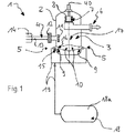
- FIG. 1 an embodiment of a jet mill 1 for carrying out the method explained above is shown schematically.
- the method according to the invention can easily be implemented with devices and means that are known per se to the person skilled in the art, but this is not intended to indicate that the person skilled in the art would also be familiar with the individual steps of the method that is the present invention was recreated.
- the jet mill 1 contains a cylindrical housing 2 which encloses a grinding chamber 3, a grinding material feed 4 approximately halfway up the grinding chamber 3, at least one grinding jet inlet 5 in the lower area of the grinding chamber 3 and a product outlet 6 in the upper area of the grinding chamber 3.
- the classifier wheel 8 can be a classifier wheel that is customary in air classifiers, the blades of which (see later for example in connection with FIG Fig. 3 ) limit radial vane channels, at the outer ends of which the sifting air enters and entrains particles of smaller grain size or mass to the central outlet and to the product outlet 6, while larger particles or particles of greater mass are rejected under the influence of centrifugal force.
- the air classifier 7 and / or at least its classifier wheel 8 are provided with at least one design feature according to FIG EP 0 472 930 B1 fitted.
- the processing temperature can be influenced, for example, by using an internal heating source 11 between the grinding material feed 4 and the area of the grinding jets 10 or a corresponding heating source 12 in the area outside the grinding material feed 4 or by processing particles of an already warm ground material, which, while avoiding heat loss, can be the grinding material task 4 arrives, for which purpose a feed pipe 13 is surrounded by a temperature-insulating jacket 14.
- the heating source 11 or 12, if it is used, can basically be arbitrary and can therefore be used for a specific purpose and selected according to the availability on the market, so that further explanations are not required.
- the temperature of the grinding jet or jets 10 is particularly relevant for the temperature, and the temperature of the material to be ground should at least approximately correspond to this grinding jet temperature.
- any substance or mixture of substances which is gaseous under the operating conditions can be used. Air and / or hydrogen gas and / or argon and / or noble gases such as. B. helium and / or nitrogen and / or mixtures of the mentioned resources are used. It should be ensured that the heat content of the operating medium after the inlet nozzle 9 of the respective milling jet inlet 5 is not significantly less than before this inlet nozzle 9.
- the pressure drop between the inlet 15 of the inlet nozzle 9 and its outlet 16 will be considerable (the pressure energy will be largely converted into flow energy) and the temperature drop will also be not insignificant.
- this temperature drop should be compensated for by the heating of the grinding stock to such an extent that the grinding stock and grinding jet 10 in the area of the center 17 of the grinding chamber 3 have the same temperature when at least two grinding jets 10 meet or a multiple of two grinding jets 10.
- a reservoir or generating device 18, such as a tank 18a is shown as a representative of any supply of an operating medium or operating medium B, from which the operating medium or operating medium B via line devices 19 to the grinding jet inlet 5 or the grinding jet inlets 5 is passed to form the grinding jet 10 or the grinding jets 10.
- a compressor can also be used to provide the appropriate operating medium B.
- a simple fan is particularly preferred, very preferably a rotary piston fan or radial fan.
- this jet mill 1 is used with a integrated dynamic air classifier 7 carried out a method for producing fine particles.
- a fluid or gas is generally used as the operating medium B, preferably the aforementioned hydrogen gas or helium gas or simply air.
- the classifier rotor 8 has a clearance height that increases or remains constant with a decreasing radius, that is to say towards its axis, with in particular the area of the classifier rotor 8 through which flow is constant.
- a fine material outlet chamber (not shown) can be provided which has a cross-sectional widening in the direction of flow.
- a particularly preferred embodiment consists in the fact that the classifying rotor 8 has an exchangeable, co-rotating immersion tube 20.
- the jet mill 1 contains, as the schematic representation in FIG Fig. 2 can be seen, an integrated air classifier 7, which is, for example, a dynamic air classifier 7, which is advantageously arranged in the center of the grinding chamber 3 of the jet mill 1 when the jet mill 1 is designed as a fluidized bed opposed jet mill or a dense bed jet mill.
- an integrated air classifier 7 which is, for example, a dynamic air classifier 7, which is advantageously arranged in the center of the grinding chamber 3 of the jet mill 1 when the jet mill 1 is designed as a fluidized bed opposed jet mill or a dense bed jet mill.
- the desired fineness of the grist can be influenced depending on the grinding gas volume flow and the classifier speed.
- a sifter housing 21 which consists essentially of the upper housing part 22 and the lower housing part 23.
- the housing upper part 22 and the housing lower part 23 are each provided with an outwardly directed peripheral flange 24 and 25 on the upper and lower edge.
- the two circumferential flanges 24, 25 lie on top of one another in the installed or functional state of the air classifier 8 and are fixed to one another by suitable means.
- suitable means for fixing are, for example, screw connections (not shown).
- Brackets (not shown) or the like can also serve as releasable fastening means.
- both circumferential flanges 24 and 25 are connected to one another by a joint 26 so that the upper housing part 22 can be pivoted upwards in the direction of arrow 27 after the flange connection means has been loosened, and the upper housing part 22 from below and the lower housing part 23 are accessible from above.
- the lower housing part 23 is in turn formed in two parts and it essentially consists of the cylindrical separating chamber housing 28 with the peripheral flange 25 at its upper open end and a discharge cone 29 which tapers conically downward.
- the discharge cone 29 and the separator housing 28 lie on top of each other at the upper and lower end with flanges 30, 31 and the two flanges 30, 31 of the discharge cone 29 and separator housing 28 are connected to each other like the peripheral flanges 24, 25 by detachable fasteners (not shown).
- the sifter housing 21 assembled in this way is in or on support arms 28a, several of which are as evenly spaced as possible around the circumference of the classifier or compressor housing 21 of the air classifier 7 of the jet mill 1 and engage the cylindrical classifying chamber housing 28.
- An essential part of the built-in housing of the air classifier 7 is again the classifier wheel 8 with an upper cover disk 32, with a lower outflow-side cover disk 33 axially spaced therefrom and with between the outer edges of the two cover disks 32 and 33, firmly connected to these and evenly around the circumference of the Classifying wheel 8 distributed blades 34 with an appropriate contour.
- the drive of the classifier wheel 8 is effected via the upper cover plate 32, while the lower cover plate 33 is the cover plate on the outflow side.
- the bearing of the classifier wheel 8 comprises an expediently forcibly driven classifier wheel shaft 35, the upper end of which is led out of the classifier housing 21 and, with its lower end, carries the classifier wheel 8 in a floating bearing within the classifier housing 21.
- the leading out of the classifier shaft 35 from the classifier housing 21 takes place in a pair of machined plates 36, 37, which close the classifier housing 21 at the upper end of an upwardly frustoconical housing end section 38, guide the classifier shaft 35 and seal this shaft passage without hindering the rotary movements of the classifier shaft 35 .
- the upper plate 36 can expediently be assigned as a flange in a rotationally fixed manner to the classifier shaft 35 and rotatably supported via pivot bearings 35a on the lower plate 37, which in turn is assigned to a housing end section 38.
- the bottom of the Cover disk 33 on the outflow side lies in the common plane between the circumferential flanges 24 and 25, so that the classifying wheel 8 is arranged in its entirety within the foldable upper housing part 22.
- the upper housing part 22 also has a tubular product feed nozzle 39 of the grinding material feed 4, the longitudinal axis of which runs parallel to the axis of rotation 40 of the classifier wheel 8 and its drive or classifier wheel shaft 35 and which is as far as possible from this axis of rotation 40 of the classifier wheel 8 and its Drive or classifying wheel shaft 35 removed, is arranged on the upper housing part 22 radially on the outside.
- the classifier housing 21 accommodates the tubular outlet stub 20, which is arranged on the same axis as the classifier wheel 8 and whose upper end lies just below the outflow-side cover disk 33 of the classifier wheel 8, but without being connected to it.
- an outlet chamber 41 is attached on the same axis, which is also tubular, but whose diameter is significantly larger than the diameter of the outlet nozzle 20 and in the present embodiment is at least twice as large as the diameter of the outlet nozzle 20.
- the outlet connection 20 is inserted into an upper cover plate 42 of the outlet chamber 41.
- the outlet chamber 41 is closed at the bottom by a removable cover 43.
- the unit of outlet nozzle 20 and outlet chamber 41 is held in a plurality of support arms 44, which are evenly distributed in a star shape around the circumference of the unit, with their inner ends in the area of the
- the outlet nozzle 20 is firmly connected to the structural unit and attached to the separator housing 21 with their outer ends.
- the outlet stub 20 is surrounded by a conical ring housing 45, the lower, larger outer diameter of which corresponds at least approximately to the diameter of the outlet chamber 41 and whose upper, smaller outer diameter corresponds at least approximately to the diameter of the classifying wheel 8.
- the support arms 44 end at the conical wall of the ring housing 45 and are firmly connected to this wall, which in turn is part of the structural unit comprising the outlet nozzle 20 and outlet chamber 41.
- the support arms 44 and the ring housing 45 are parts of a scavenging air device (not shown), the scavenging air preventing the penetration of matter from the interior of the separator housing 21 into the gap between the separator wheel 8 or, more precisely, its lower cover plate 3 and the outlet nozzle 20.
- the support arms 44 are designed as tubes, with their outer end sections passed through the wall of the separator housing 21 and connected to a purge air source (not shown) via a suction filter 46 .
- the ring housing 45 is closed at the top by a perforated plate 47 and the gap itself can be adjusted by an axially adjustable ring disk in the area between the perforated plate 47 and the lower cover disk 33 of the classifier wheel 8.
- the outlet from the exit chamber 41 is from a Fine material discharge pipe 48 is formed, which is led from the outside into the classifier housing 21 and is connected to the outlet chamber 41 in a tangential arrangement.
- the fines discharge pipe 48 is part of the product outlet 6.
- a deflector cone 49 serves to cover the confluence of the fines discharge pipe 48 with the outlet chamber 41.
- a classifying air inlet spiral 50 and a coarse material discharge 51 are assigned to the housing end section 38 in a horizontal arrangement.
- the direction of rotation of the classifying air inlet spiral 50 is opposite to the direction of rotation of the classifying wheel 8.
- the coarse material discharge 51 is detachably assigned to the housing end section 38, a flange 52 being assigned to the lower end of the housing end section 38 and a flange 53 being assigned to the upper end of the coarse material discharge 51, and both flanges 52 and 53 being detachably connected to one another by known means when the air classifier 7 is ready for use.
- the dispersion zone to be designed is denoted by 54.
- Machined (chamfered) flanges on the inner edge for a clean flow guidance and a simple lining are denoted by 55.
- an exchangeable protective tube 56 is placed on the inner wall of the outlet connection 20 as a wear part and a corresponding exchangeable protective tube 57 can be placed on the inner wall of the outlet chamber 41.
- the air inlet spiral 50 Classifying air introduced into the air classifier 7 under a pressure gradient and with an appropriately selected entry speed.
- the classifying air rises in a spiral upward into the area of the classifying wheel 8.
- the "product" of solid particles of different mass is entered into the classifier housing 21 via the product feed nozzle 39. From this product, the coarse material, ie the particle fraction with a greater mass, reaches the area of the coarse material discharge 51 against the classifying air and is made available for further processing.
- the fine material ie the particle fraction with a lower mass is mixed with the classifying air, passes radially from the outside to the inside through the classifying wheel 8 into the outlet nozzle 20, into the outlet chamber 41 and finally via a fine material outlet pipe 48 into a fine material outlet or outlet 58 and from there in a filter in which the operating medium in the form of a fluid, such as air, and fine material are separated from one another.
- Coarser fine material components are thrown radially out of the classifier wheel 8 and mixed with the coarse material in order to leave the classifier housing 21 with the coarse material or to circulate in the classifier housing 21 until it has become fine material of such a grain size that it is discharged with the classifying air.
- the air classifier 7 can again be well maintained and damaged components can be replaced with relatively little effort and within short maintenance times.
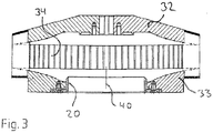
- FIG. 3 While in the schematic representation of the Fig. 2 the classifying wheel 8 with the two cover disks 32 and 33 and the blade ring 59 with the blades 34 arranged between them is shown in a known, customary form with parallel and parallel-surfaced cover disks 32 and 33, is shown in FIG Fig. 3 the classifier wheel 8 is shown for a further embodiment of the air classifier 7 of an advantageous development.
- This classifying wheel 8 contains, in addition to the blade ring 59 with the blades 34, the upper cover disk 32 and the lower outflow-side cover disk 33, which is axially spaced therefrom, and is about the axis of rotation 40 and thus the longitudinal axis of the air classifier 7 can be rotated.
- the diametrical extension of the classifier wheel 8 is perpendicular to the axis of rotation 40, ie to the longitudinal axis of the air classifier 7, regardless of whether the axis of rotation 40 and thus the named longitudinal axis is perpendicular or extends horizontally.
- the lower cover disk 33 on the outflow side concentrically surrounds the outlet nozzle 20.
- the blades 34 are connected to both cover disks 33 and 32.
- the two cover disks 32 and 33 are now conical, deviating from the prior art, and were preferably such that the distance between the upper cover disk 32 and the outflow-side cover disk 33 from the rim 59 of the blades 34 inwards, ie towards the axis of rotation 40, increases and although preferably continuously, such as linear or non-linear, and with further preference so that the area of the cylinder jacket through which the flow flows remains constant for each radius between the blade outlet edges and outlet nozzle 20.
- the outflow velocity which is decreasing due to the decreasing radius in known solutions, remains constant in this solution.
- the shape of the non-parallel cover disk can be such that at least approximately such that the area of the cylinder jacket through which the flow flows is constant for each radius between the blade outlet edges and outlet nozzle 20 remains.
- a surface modification agent is added during the grinding.
- the surface modification in the process according to the invention is particularly effective because when the particles collide inside the mill, a cloud of material is formed from the ground, fine particles into which the surface modification agent can be introduced, particularly preferably sprayed. As a result, the surface modification agent does not come into contact with the walls of the mill during the bonding reaction, so that caking is prevented. This caking represents a major disadvantage and a major problem of mechanical or classifying mechanical mills.
- the surface modification agent is preferably introduced via nozzles, preferably two-component nozzles, whereby the atomizing medium can be the same medium as the grinding gas.
- the point of injection is preferably within the immediate grinding zone, particularly preferably at the same height as the grinding nozzles.
- a particular advantage of this type of surface modification is the fact that active / fresh surfaces that have arisen are available for coating / doping quasi in situ - as a result of the grinding. This increases the interaction of the grinding material surfaces with the coating / doping agent and can lead, among other things, to a stronger bond.
- Another advantage can be that the simultaneous coating / doping during the grinding process Stabilization of the millbase (e.g. against reagglomeration) can be achieved.
- all surface modification agents can be used in the process according to the invention which can be sprayed into the grinding chamber as a liquid, solution or melt under the grinding conditions.
- Preferred surface modification agents in the context of the present invention are soda waterglass, alkali (e.g. NaOH and KOH), acids (e.g. sulfuric acid, hydrochloric acid, nitric acid), organic silicon compounds (e.g. modified or unmodified silanes, polysiloxanes, organically modified polysiloxanes, silicone oils, silicone polyether acrylate), organic Polymers, acrylates, polyvinyl alcohol (PVA), waxes (eg polyethylene waxes) and metal salts (doping).
- alkali e.g. NaOH and KOH
- acids e.g. sulfuric acid, hydrochloric acid, nitric acid
- organic silicon compounds e.g. modified or unmodified silanes, polysiloxanes, organically modified polysiloxanes, silicone oils, silicone polyether
- Non-exclusive examples of such surface modifying agents are given in US Pat WO 2004/055120 , the WO 2004/055105 , the WO 2004/054927 or the EP 1477457 called. The content of these documents is hereby explicitly included in the subject matter of the present invention.
- silicone polyether acrylate polymers which, for. B. be sold under the name TegoRad®. They are particularly preferably silicone polyether acrylate polymers or silicone polyether methacrylate polymers such as those in FIG EP 0999230 A1 are described and very particularly preferably to polymers corresponding to EP 0999230 A1 with a polyether excess of 1 to 50% by weight, preferably 5 to 30% by weight, particularly preferably 10 to 20% by weight.
- TegoRad® silicone polyether acrylate polymers
- silicone polyether methacrylate polymers such as those in FIG EP 0999230 A1 are described and very particularly preferably to polymers corresponding to EP 0999230 A1 with a polyether excess of 1 to 50% by weight, preferably 5 to 30% by weight, particularly preferably 10 to 20% by weight.
- solids composed of amorphous SiO 2 in particular precipitated silicas, silicates (e.g. aluminosilicates), arc silica, pyrogenic silicas, semigels or silica gels are particularly preferred in this variant of the process according to the invention and ground with silicone polyether acrylates, polyvinyl alcohols (PVA), acrylates and Wax coated or doped.
- This combination of coating agent or doping agent and millbase is particularly preferred because, in conventional methods, up to now a coating or doping and then grinding in mechanical or classifying mechanical mills had to take place first.
- the application of laser diffraction to determine particle size distributions of powdery solids is based on the phenomenon that particles, depending on their size, emit light from a monochrome laser beam with different intensity patterns in all directions scatter or bend.
- the subsequent implementation of the measurement is described using samples of precipitated silica.
- the sample preparation and measurement are carried out with deionized water as the dispersing liquid, in the case of precipitated silicas that are not sufficiently wettable with water, with pure ethanol.
- the LS 230 laser diffraction measuring device (Beckman Coulter; measuring range: 0.04-2000 pm) and the liquid module (Small Volume Module Plus, 120 ml, Beckman Coulter) are allowed to warm up for 2 hours and the module is also rinsed three times VE water.
- the rinsing process is carried out with pure ethanol.
- the sample can be added directly as a powdery solid using a spatula, or in suspended form using a 2 ml disposable pipette into the liquid module (Small Volume Module Plus) of the device.
- the software of the laser diffraction measuring device LS 230 reports an "OK".
- Ground precipitated silicas are dispersed by ultrasound for 60 seconds using the Vibra Cell VCX 130 ultrasonic processor from Sonics with an ultrasonic converter CV 181 and 6 mm ultrasonic tip at 70% amplitude and simultaneous pumping in the liquid module. In the case of unmilled precipitated silicas, the dispersion takes place without ultrasound by pumping in the liquid module for 60 seconds. The measurement takes place at room temperature. From the raw data, the device software calculates the volume distribution of the particle sizes and the d50 value (median value) based on the Mie theory with the aid of the previously defined optical parameters (.rfd file).
- the ISO 13320 Particle Size Analysis - Guide to Laser Diffraction Methods describes the laser diffraction method for determining particle size distributions in detail. There the person skilled in the art will find a list of the optical parameters of common solids and dispersing liquids relevant for an evaluation according to the Mie theory.
- the coating agent is applied via a two-substance nozzle (into the Figures 1 to 3 not shown), which is located in the same plane as the grinding nozzles (3 grinding nozzles at a distance of 120 ° and between two of these grinding nozzles the two-substance nozzle at a distance of 60 °), injected into the mill.
- TegoRad® 2300 7.4 percent by mass of TegoRad® 2300 (TegoRad® 2300 has a carbon content of approx. 43.9% by weight) was given up. A carbon content of 3.2% by weight was found in the end product, ie, taking into account the C content of TegoRad® 2300, an approximately quantitative coverage was achieved without loss of polyether. With a wet coating and the same percentage addition of TegoRad® 2300, only between 2.5 and 2.8% by weight of carbon was found in the end product. A considerable amount of the surface modification agent is therefore not found on the silica during wet coating, but was washed out with the water. This shows the particular advantage of the process according to the invention when surface-modifying agents are coated with water-soluble fractions on carrier materials. The product has ad 50 of 4.7 ⁇ m.
- Sipernat® 50 from Evonik Degussa GmbH was in a fluidized bed opposed jet mill, type CGS 50, from Netzsch-Condux, at a grinding air temperature of 80 ° C. and a pressure of 0.36 bar (abs) and with PE wax from Deurex (melting range: 98-103 ° C).
- the coating is carried out analogously to Example 1.
- the product has ad 50 of 5.8 ⁇ m.
- the abrasive toothpaste silica Sident® 9 from Evonik Degussa GmbH was ground once in the fluidized bed opposed jet mill, type CGS 50, from Netzsch-Condux, as in Example 2, using the process according to the invention.
- Sident® 9 was ground in a mechanical beater mill UPZ 160 from Alpine.
- abrasion of approx. 6.5 g resulted, which corresponds to an increase in iron contamination of 11 ppm.
- the increase in iron contamination was less than 1 ppm.
Landscapes
- Chemical & Material Sciences (AREA)
- Organic Chemistry (AREA)
- Engineering & Computer Science (AREA)
- Life Sciences & Earth Sciences (AREA)
- Materials Engineering (AREA)
- Wood Science & Technology (AREA)
- Food Science & Technology (AREA)
- Disintegrating Or Milling (AREA)
- Silicon Compounds (AREA)
- Combined Means For Separation Of Solids (AREA)
Claims (12)
- Procédé de génération de particules fines au moyen d'un broyeur à jet, caractérisé en ce que le gaz de broyage présente une pression ≤ 4 bar (abs) et une température inférieure à 100 °C, un agent de revêtement ou un agent dopant est ajouté pendant le broyage de telle sorte qu'au moins des parties de la surface des particules du produit broyé soient garnies avec l'agent de revêtement ou l'agent dopant, et le produit broyé est du SiO2 amorphe, et l'agent de revêtement ou l'agent dopant est du polyéther-acrylate de silicium, de l'alcool polyvinylique, de l'acrylate ou de la cire.
- Procédé selon la revendication 1, caractérisé en ce qu'un broyeur à tube ovale ou un broyeur à jet en spirale muni d'un tamisage statique est utilisé.
- Procédé selon la revendication 1, caractérisé en ce qu'un broyeur à contre-jet en lit fluidisé ou un broyeur à jet en lit dense, de préférence muni d'un tamiseur, de manière particulièrement préférée muni d'un tamiseur pneumatique dynamique, de manière tout particulièrement préférée un broyeur à jet (1) muni d'un tamiseur pneumatique dynamique intégré dans celui-ci (7), est utilisé.
- Procédé selon la revendication 3, caractérisé en ce que le tamiseur pneumatique (7) contient un rotor de tamisage ou une roue de tamisage (8) ayant une hauteur intérieure croissante ou constante lorsque le rayon est décroissant, de telle sorte que lors de l'exploitation, la surface traversée du rotor ou de la roue de tamisage (8) soit au moins approximativement constante.
- Procédé selon la revendication 3 ou 4, caractérisé en ce que le tamiseur pneumatique (7) contient un rotor de tamisage ou une roue de tamisage (8) muni d'un tube d'immersion (20) notamment remplaçable, qui est conçu de telle sorte qu'il soit mis en rotation lorsque le rotor de tamisage ou la roue de tamisage (8) est en rotation.
- Procédé selon l'une quelconque des revendications 3 à 5, caractérisé en ce qu'une chambre de sortie de produit fin (41) est prévue, qui présente un élargissement de section transversale dans la direction d'écoulement.
- Procédé selon l'une quelconque des revendications 1 à 6, caractérisé en ce qu'un ventilateur simple, de préférence un ventilateur à piston rotatif ou un ventilateur radial, est utilisé pour générer la pression et la température de l'agent d'exploitation.
- Procédé selon l'une quelconque des revendications 1 à 7, caractérisé en ce que de l'air et/ou de l'argon et/ou des gaz nobles, de préférence de l'hélium, et/ou de l'azote et/ou un mélange des agents d'exploitation mentionnés, est utilisé en tant qu'agent d'exploitation.
- Procédé selon l'une quelconque des revendications 1 à 8, caractérisé en ce que la température du gaz de broyage est inférieure ou égale à 95 °C, de préférence inférieure ou égale à 90 °C, de manière particulièrement préférée inférieure ou égale à 80 °C et de manière tout particulièrement préférée de 15 à 80 °C ou de 50 à 80 °C ou de 15 à 50 °C.
- Procédé selon l'une quelconque des revendications 1 à 9, caractérisé en ce que la pression du gaz de broyage est inférieure à 3 bar, de préférence inférieure à 2 bar, de manière particulièrement préférée inférieure à 1 bar, de manière spécialement préférée de 0,5 à 1 bar et de manière tout spécialement préférée de 0,15 à 0,5 bar.
- Procédé selon la revendication 9 ou 10, caractérisé en ce qu'il est exploité avec la combinaison suivante de pression de gaz de broyage et de température : 0,15 à 0,5 bar et 15 à 50 °C ou 0,15 à 0,5 bar et 50 à 80 °C.
- Produit pouvant être obtenu par un procédé selon l'une quelconque des revendications 1 à 10.
Applications Claiming Priority (1)
| Application Number | Priority Date | Filing Date | Title |
|---|---|---|---|
| DE102009045116A DE102009045116A1 (de) | 2009-09-29 | 2009-09-29 | Niederdruckvermahlungsverfahren |
Publications (3)
| Publication Number | Publication Date |
|---|---|
| EP2301667A2 EP2301667A2 (fr) | 2011-03-30 |
| EP2301667A3 EP2301667A3 (fr) | 2017-11-15 |
| EP2301667B1 true EP2301667B1 (fr) | 2020-12-16 |
Family
ID=43532988
Family Applications (1)
| Application Number | Title | Priority Date | Filing Date |
|---|---|---|---|
| EP10174068.6A Active EP2301667B1 (fr) | 2009-09-29 | 2010-08-26 | Procédé de broyage basse pression |
Country Status (9)
| Country | Link |
|---|---|
| US (1) | US8864056B2 (fr) |
| EP (1) | EP2301667B1 (fr) |
| JP (1) | JP6032864B2 (fr) |
| KR (1) | KR101364779B1 (fr) |
| CN (2) | CN102774841A (fr) |
| BR (1) | BRPI1003864B1 (fr) |
| DE (1) | DE102009045116A1 (fr) |
| ES (1) | ES2848429T3 (fr) |
| TW (1) | TWI503175B (fr) |
Families Citing this family (26)
| Publication number | Priority date | Publication date | Assignee | Title |
|---|---|---|---|---|
| CN102261821A (zh) * | 2011-05-16 | 2011-11-30 | 蚌埠鑫源石英材料有限公司 | 利用热烟气对粉体材料进行快速烘干打散的方法 |
| DE102011102614A1 (de) * | 2011-05-27 | 2012-11-29 | Roland Nied | Verfahren zum Betrieb einer Strahlmühle sowie Strahlmühle |
| CN102728841B (zh) * | 2012-07-10 | 2014-06-04 | 交城县融和磁材有限公司 | 一种烧结钕铁硼永磁材料的气流磨制粉装置及方法 |
| DE102013000426A1 (de) * | 2013-01-14 | 2014-07-17 | Roland Nied | Verfahren zur Strahlmahlung sowie Strahlmühle dafür |
| DE102014211037A1 (de) | 2014-06-10 | 2015-12-17 | Wacker Chemie Ag | Siliciumkeimpartikel für die Herstellung von polykristallinem Siliciumgranulat in einem Wirbelschichtreaktor |
| US9180463B1 (en) * | 2014-08-29 | 2015-11-10 | Joseph R. Fitzgerald | Method for fractionation of dry material using accelerators |
| KR20160064567A (ko) * | 2014-11-28 | 2016-06-08 | 코오롱글로텍주식회사 | 기능성 원사의 방사 첨가제로서의 구리 화합물의 개질 방법 |
| DK3346990T3 (da) | 2015-09-09 | 2020-06-02 | Vectura Ltd | Fremgangsmåde til stråleformaling |
| CN105728147B (zh) * | 2016-03-07 | 2018-05-08 | 钟文虎 | 对撞式气流粉碎机构及粉碎机 |
| CN109789425B (zh) | 2016-08-09 | 2021-05-04 | 佐竹化学机械工业株式会社 | 分级装置 |
| CN107188211B (zh) * | 2016-08-16 | 2019-04-05 | 上海奉坤新材料有限公司 | 改进的重质碳酸钙的制作方法 |
| CN109906201B (zh) | 2016-11-07 | 2022-08-09 | 瓦克化学股份公司 | 用于研磨含硅固体的方法 |
| EP3630882A4 (fr) | 2017-06-02 | 2021-02-24 | W.R. Grace & Co.-Conn. | Particules revêtues et procédés pour leur production et leur utilisation |
| DE102017209874A1 (de) | 2017-06-12 | 2018-12-13 | Evonik Degussa Gmbh | Verfahren zur Herstellung von wachsbeschichteter Kieselsäure |
| CN111655774B (zh) | 2017-08-03 | 2023-05-02 | 格雷斯公司 | 基于二氧化硅的消光剂及其制备和使用方法 |
| KR102079383B1 (ko) * | 2018-05-02 | 2020-02-19 | 농업회사법인 명성제분 주식회사 | 기능미의 제조 방법 |
| US12427444B2 (en) | 2018-06-15 | 2025-09-30 | W.R. Grace & Co.-Conn. | Defoamer active, manufacturing thereof, and deforming formulation |
| BR112020025480A2 (pt) * | 2018-06-15 | 2021-03-16 | W. R. Grace & Co.-Conn | Ativo eliminador de espuma, método de fabricação do mesmo e formulação desespumante |
| KR102505661B1 (ko) | 2018-09-26 | 2023-03-06 | 사타케 멀티믹스 가부시키가이샤 | 분급 로터 및 분급 장치 |
| AU2020207237B2 (en) * | 2019-01-09 | 2025-02-06 | Qwave Solutions, Inc | Methods of jet milling and systems |
| EP3946928A4 (fr) * | 2019-04-04 | 2023-01-25 | W. R. Grace & Co.-Conn | Compositions de revêtement pour films hydrophobes et articles ayant des surfaces hydrophobes |
| US20220315775A1 (en) * | 2019-05-07 | 2022-10-06 | W. R. Grace & Co.-Conn. | Coating compositions for hydrophobic films and articles having hydrophobic surfaces |
| CN110681455B (zh) * | 2019-10-09 | 2021-06-04 | 沪宝新材料科技(上海)股份有限公司 | 外墙真石漆涂料工艺系统及其工艺方法和配方 |
| EP3995320A1 (fr) * | 2020-11-09 | 2022-05-11 | Continental Reifen Deutschland GmbH | Procédé sans solvant à efficacité énergétique pour l'organosilanisation des matériaux de silicate et de dioxyde de silicium |
| WO2025060945A1 (fr) | 2023-09-22 | 2025-03-27 | Evonik Operations Gmbh | Procédé de préparation d'oxyde métallique ou de silice pour des applications électroniques utilisant de la silice ou de l'oxyde métallique sphérique recyclé |
| CN119217581B (zh) * | 2024-10-22 | 2025-04-25 | 杭州中平化工有限公司 | 一种pbs改性塑料母粒生产用气流磨装置及其生产工艺 |
Family Cites Families (30)
| Publication number | Priority date | Publication date | Assignee | Title |
|---|---|---|---|---|
| GB1034143A (en) | 1965-02-04 | 1966-06-29 | Corsets Silhouette Ltd | Improvements in foundation garments |
| DE3815670A1 (de) * | 1988-05-07 | 1990-01-25 | Degussa | Feinteilige faellungskieselsaeure mit hoher struktur, verfahren zu seiner herstellung und verwendung |
| JP2633974B2 (ja) * | 1990-04-18 | 1997-07-23 | 株式会社日立製作所 | 試料のイオン化および質量分析のための装置 |
| US5252110A (en) | 1990-08-01 | 1993-10-12 | Roland Nied | Preferably vertical air separator |
| US5244481A (en) | 1990-08-01 | 1993-09-14 | Roland Nied | Preferably vertical air separator |
| JP2503826B2 (ja) * | 1992-02-05 | 1996-06-05 | 株式会社栗本鐵工所 | 気流式粉砕装置 |
| ES2104359T3 (es) * | 1993-02-12 | 1997-10-01 | Cabot Corp | Silice modificada superficialmente. |
| EP0714837B1 (fr) * | 1994-11-30 | 2000-09-13 | Sintokogio, Ltd. | Dispositif pour séparer les matériaux pulvérulents d'un courant d'air |
| JPH10167968A (ja) | 1996-10-09 | 1998-06-23 | Takeda Chem Ind Ltd | マイクロパーティクルの製造法 |
| MY117802A (en) * | 1997-06-13 | 2004-08-30 | Mizusawa Industrial Chem | Amorphous silica particles having a double structure, process for producing the same and use |
| DE19824062A1 (de) | 1998-05-29 | 1999-12-02 | Roland Nied | Mahlverfahren unter Verwendung einer Strahlmühle |
| DE19850507C1 (de) | 1998-11-03 | 2000-05-04 | Goldschmidt Ag Th | Verfahren zur Herstellung von Acrylsäureestern und/oder Methacrylsäureestern von hydroxyfunktionellen Siloxanen und/oder polyoxyalkylenmodifizierten Siloxanen und deren Verwendung |
| DE60038225T2 (de) * | 1999-06-16 | 2009-03-19 | Kao Corp. | Oberflächenmodifizierer |
| CN1287023A (zh) * | 1999-09-08 | 2001-03-14 | 株式会社威士诺 | 喷射式粉碎机 |
| KR20050091733A (ko) | 2002-12-18 | 2005-09-15 | 데구사 악티엔게젤샤프트 | 표면 개질된 에어로겔형 구조화 실리카 |
| KR100983209B1 (ko) | 2002-12-18 | 2010-09-20 | 에보닉 데구사 게엠베하 | 텍스쳐 피복된 실리카 |
| CN100436548C (zh) | 2002-12-18 | 2008-11-26 | 德古萨公司 | 结构改性二氧化硅 |
| US20040121003A1 (en) | 2002-12-19 | 2004-06-24 | Acusphere, Inc. | Methods for making pharmaceutical formulations comprising deagglomerated microparticles |
| US6962006B2 (en) * | 2002-12-19 | 2005-11-08 | Acusphere, Inc. | Methods and apparatus for making particles using spray dryer and in-line jet mill |
| EP1477457B1 (fr) | 2003-05-14 | 2007-07-25 | Degussa GmbH | Dioxyde de silicium précipité modifié superficiellement |
| DE102004027874A1 (de) * | 2004-06-08 | 2006-01-05 | Bayer Chemicals Ag | Verfahren zur Herstellung von feinteiligen Treibmittelpulvern |
| DE102005036211A1 (de) | 2005-08-02 | 2007-02-08 | Lanxess Deutschland Gmbh | Strahlmühle mit integriertem dynamischen Sichter |
| US7289706B2 (en) | 2005-11-30 | 2007-10-30 | Corning Incorporated | Optical fiber ribbon with improved stripability |
| DE102006017472A1 (de) | 2006-04-13 | 2007-10-18 | Nied, Roland, Dr. Ing. | Verfahren zur Erzeugung feinster Partikel mittels einer Strahlmühle |
| DE102006023193A1 (de) | 2006-05-17 | 2007-11-22 | Nied, Roland, Dr.-Ing. | Verfahren zur Erzeugung feinster Partikel mittels einer Strahlmühle |
| DE102006048850A1 (de) * | 2006-10-16 | 2008-04-17 | Evonik Degussa Gmbh | Amorphe submicron Partikel |
| CN100584894C (zh) * | 2006-07-14 | 2010-01-27 | 浙江大学 | 一种用于紫外光固化胶粘剂中的纳米SiO2改性的方法 |
| DE102006048864A1 (de) * | 2006-10-16 | 2008-04-17 | Roland Dr. Nied | Verfahren zur Erzeugung feinster Partikel und Strahlmühle dafür sowie Windsichter und Betriebsverfahren davon |
| CN100435963C (zh) * | 2007-04-30 | 2008-11-26 | 北京航空航天大学 | 采用气流粉碎方法制备高纯纳米颗粒的工艺和装置 |
| US7985292B2 (en) * | 2007-11-26 | 2011-07-26 | Evonik Degussa Corporation | Precipitated silica for thickening and creating thixotropic behavior in liquid systems |
-
2009
- 2009-09-29 DE DE102009045116A patent/DE102009045116A1/de not_active Withdrawn
-
2010
- 2010-08-26 ES ES10174068T patent/ES2848429T3/es active Active
- 2010-08-26 EP EP10174068.6A patent/EP2301667B1/fr active Active
- 2010-09-20 CN CN2012102454669A patent/CN102774841A/zh active Pending
- 2010-09-20 CN CN201010290438XA patent/CN102029215A/zh active Pending
- 2010-09-24 TW TW099132400A patent/TWI503175B/zh active
- 2010-09-28 BR BRPI1003864-7A patent/BRPI1003864B1/pt active IP Right Grant
- 2010-09-28 US US12/892,520 patent/US8864056B2/en active Active
- 2010-09-28 KR KR1020100093601A patent/KR101364779B1/ko active Active
- 2010-09-29 JP JP2010218236A patent/JP6032864B2/ja active Active
Also Published As
| Publication number | Publication date |
|---|---|
| US8864056B2 (en) | 2014-10-21 |
| DE102009045116A1 (de) | 2011-03-31 |
| CN102774841A (zh) | 2012-11-14 |
| TW201125640A (en) | 2011-08-01 |
| EP2301667A3 (fr) | 2017-11-15 |
| JP2011072993A (ja) | 2011-04-14 |
| KR101364779B1 (ko) | 2014-02-21 |
| CN102029215A (zh) | 2011-04-27 |
| JP6032864B2 (ja) | 2016-11-30 |
| US20110073689A1 (en) | 2011-03-31 |
| ES2848429T3 (es) | 2021-08-09 |
| BRPI1003864A2 (pt) | 2013-01-29 |
| TWI503175B (zh) | 2015-10-11 |
| EP2301667A2 (fr) | 2011-03-30 |
| KR20110035926A (ko) | 2011-04-06 |
| BRPI1003864B1 (pt) | 2020-08-11 |
Similar Documents
| Publication | Publication Date | Title |
|---|---|---|
| EP2301667A2 (fr) | Procédé de broyage basse pression | |
| EP2089163B1 (fr) | Particule submicronique amorphe | |
| EP2101918B1 (fr) | Procédé de production de particules extrêmement fines, pulvérisateur à jet approprié, séparateur pneumatique et procédé d'exploitation correspondant | |
| EP2959975A1 (fr) | Procede de production de particules fines a l'aide d'un broyeur a jet et broyeur a jet associe | |
| EP2219996B1 (fr) | Nouvel acide silicilique précipité permettant d'obtenir un épaississement et de produire un comportement thixotrope dans des systèmes liquides | |
| DE4447321C2 (de) | Rührwerksmühle für die nasse Feinzerkleinerung, mit Separator zur Zurückhaltung von Mahlperlen | |
| DE69203643T2 (de) | Trockenzermahlung. | |
| EP2209739B1 (fr) | Acides siliciques précipités utilisés pour produire des formulations de caoutchouc de silicone rtv-1 stables au stockage, sans stabilisant | |
| EP2004329B1 (fr) | Procédé de génération de particules très fines au moyen d'un pulvérisateur à jet | |
| DE102013103012A1 (de) | Granulatkonditionierer | |
| EP2024093A1 (fr) | Procédé de production de très fines particules au moyen d'un broyeur à jet fluide | |
| EP1080786A1 (fr) | Procédé, dispositif et système pour broyeur à jet à lit fluidisé | |
| WO2018082789A1 (fr) | Procédé pour broyer des matières solides contenant du silicium | |
| WO2018228878A1 (fr) | Procédé pour produire de l'acide silicique recouvert de cire | |
| EP1866383B1 (fr) | Pigment a base de rutile et son procede de fabrication | |
| DE387995C (de) | Verfahren zur Zerkleinerung von festen Stoffen auf trockenem Wege bis zu einer Teilchengroesse unter 0.008 mm Durchmesser | |
| DE1288890B (de) | Verfahren und Vorrichtung zum trockenen Feinstzerkleinern von Feststoffen | |
| DE3028343C2 (fr) | ||
| DE102012217304A1 (de) | Vorrichtung zum Zerkleinern von Partikeln in einer Suspension und Verfahren dazu | |
| DE3535989A1 (de) | Verfahren zur herstellung von glimmerpulver in feinteiliger form | |
| DE1871056U (de) | Sichtermuehle. | |
| DE102014110754A1 (de) | Verfahren zur Zerkleinerung anorganischer Feststoffe |
Legal Events
| Date | Code | Title | Description |
|---|---|---|---|
| PUAI | Public reference made under article 153(3) epc to a published international application that has entered the european phase |
Free format text: ORIGINAL CODE: 0009012 |
|
| 17P | Request for examination filed |
Effective date: 20100826 |
|
| AK | Designated contracting states |
Kind code of ref document: A2 Designated state(s): AL AT BE BG CH CY CZ DE DK EE ES FI FR GB GR HR HU IE IS IT LI LT LU LV MC MK MT NL NO PL PT RO SE SI SK SM TR |
|
| AX | Request for extension of the european patent |
Extension state: BA ME RS |
|
| RIC1 | Information provided on ipc code assigned before grant |
Ipc: B02C 19/06 20060101AFI20170418BHEP |
|
| PUAL | Search report despatched |
Free format text: ORIGINAL CODE: 0009013 |
|
| AK | Designated contracting states |
Kind code of ref document: A3 Designated state(s): AL AT BE BG CH CY CZ DE DK EE ES FI FR GB GR HR HU IE IS IT LI LT LU LV MC MK MT NL NO PL PT RO SE SI SK SM TR |
|
| AX | Request for extension of the european patent |
Extension state: BA ME RS |
|
| RIC1 | Information provided on ipc code assigned before grant |
Ipc: C09D 7/12 20060101ALI20171006BHEP Ipc: C08K 9/06 20060101ALI20171006BHEP Ipc: C08L 83/12 20060101ALI20171006BHEP Ipc: C09C 3/10 20060101ALI20171006BHEP Ipc: B02C 19/06 20060101AFI20171006BHEP Ipc: C09D 7/00 20060101ALI20171006BHEP |
|
| RAP1 | Party data changed (applicant data changed or rights of an application transferred) |
Owner name: EVONIK DEGUSSA GMBH |
|
| RAP1 | Party data changed (applicant data changed or rights of an application transferred) |
Owner name: EVONIK OPERATIONS GMBH |
|
| GRAP | Despatch of communication of intention to grant a patent |
Free format text: ORIGINAL CODE: EPIDOSNIGR1 |
|
| STAA | Information on the status of an ep patent application or granted ep patent |
Free format text: STATUS: GRANT OF PATENT IS INTENDED |
|
| RIC1 | Information provided on ipc code assigned before grant |
Ipc: C09C 1/30 20060101ALI20200902BHEP Ipc: B02C 19/06 20060101AFI20200902BHEP Ipc: C09D 7/42 20180101ALI20200902BHEP Ipc: C09D 7/65 20180101ALI20200902BHEP Ipc: C09C 3/10 20060101ALI20200902BHEP Ipc: C08K 9/06 20060101ALI20200902BHEP Ipc: C09C 3/04 20060101ALI20200902BHEP |
|
| INTG | Intention to grant announced |
Effective date: 20201005 |
|
| RIN1 | Information on inventor provided before grant (corrected) |
Inventor name: MEIER, KARL Inventor name: PAULAT, FLORIAN Inventor name: LINDNER, GOTTLIEB |
|
| GRAS | Grant fee paid |
Free format text: ORIGINAL CODE: EPIDOSNIGR3 |
|
| GRAA | (expected) grant |
Free format text: ORIGINAL CODE: 0009210 |
|
| STAA | Information on the status of an ep patent application or granted ep patent |
Free format text: STATUS: THE PATENT HAS BEEN GRANTED |
|
| AK | Designated contracting states |
Kind code of ref document: B1 Designated state(s): AL AT BE BG CH CY CZ DE DK EE ES FI FR GB GR HR HU IE IS IT LI LT LU LV MC MK MT NL NO PL PT RO SE SI SK SM TR |
|
| REG | Reference to a national code |
Ref country code: GB Ref legal event code: FG4D Free format text: NOT ENGLISH |
|
| REG | Reference to a national code |
Ref country code: IE Ref legal event code: FG4D Free format text: LANGUAGE OF EP DOCUMENT: GERMAN |
|
| REG | Reference to a national code |
Ref country code: DE Ref legal event code: R096 Ref document number: 502010016819 Country of ref document: DE |
|
| REG | Reference to a national code |
Ref country code: AT Ref legal event code: REF Ref document number: 1345098 Country of ref document: AT Kind code of ref document: T Effective date: 20210115 |
|
| REG | Reference to a national code |
Ref country code: FI Ref legal event code: FGE |
|
| REG | Reference to a national code |
Ref country code: NL Ref legal event code: FP |
|
| PG25 | Lapsed in a contracting state [announced via postgrant information from national office to epo] |
Ref country code: GR Free format text: LAPSE BECAUSE OF FAILURE TO SUBMIT A TRANSLATION OF THE DESCRIPTION OR TO PAY THE FEE WITHIN THE PRESCRIBED TIME-LIMIT Effective date: 20210317 Ref country code: NO Free format text: LAPSE BECAUSE OF FAILURE TO SUBMIT A TRANSLATION OF THE DESCRIPTION OR TO PAY THE FEE WITHIN THE PRESCRIBED TIME-LIMIT Effective date: 20210316 |
|
| PG25 | Lapsed in a contracting state [announced via postgrant information from national office to epo] |
Ref country code: LV Free format text: LAPSE BECAUSE OF FAILURE TO SUBMIT A TRANSLATION OF THE DESCRIPTION OR TO PAY THE FEE WITHIN THE PRESCRIBED TIME-LIMIT Effective date: 20201216 Ref country code: SE Free format text: LAPSE BECAUSE OF FAILURE TO SUBMIT A TRANSLATION OF THE DESCRIPTION OR TO PAY THE FEE WITHIN THE PRESCRIBED TIME-LIMIT Effective date: 20201216 Ref country code: BG Free format text: LAPSE BECAUSE OF FAILURE TO SUBMIT A TRANSLATION OF THE DESCRIPTION OR TO PAY THE FEE WITHIN THE PRESCRIBED TIME-LIMIT Effective date: 20210316 |
|
| PG25 | Lapsed in a contracting state [announced via postgrant information from national office to epo] |
Ref country code: HR Free format text: LAPSE BECAUSE OF FAILURE TO SUBMIT A TRANSLATION OF THE DESCRIPTION OR TO PAY THE FEE WITHIN THE PRESCRIBED TIME-LIMIT Effective date: 20201216 |
|
| REG | Reference to a national code |
Ref country code: LT Ref legal event code: MG9D |
|
| PG25 | Lapsed in a contracting state [announced via postgrant information from national office to epo] |
Ref country code: RO Free format text: LAPSE BECAUSE OF FAILURE TO SUBMIT A TRANSLATION OF THE DESCRIPTION OR TO PAY THE FEE WITHIN THE PRESCRIBED TIME-LIMIT Effective date: 20201216 Ref country code: PT Free format text: LAPSE BECAUSE OF FAILURE TO SUBMIT A TRANSLATION OF THE DESCRIPTION OR TO PAY THE FEE WITHIN THE PRESCRIBED TIME-LIMIT Effective date: 20210416 Ref country code: SK Free format text: LAPSE BECAUSE OF FAILURE TO SUBMIT A TRANSLATION OF THE DESCRIPTION OR TO PAY THE FEE WITHIN THE PRESCRIBED TIME-LIMIT Effective date: 20201216 Ref country code: SM Free format text: LAPSE BECAUSE OF FAILURE TO SUBMIT A TRANSLATION OF THE DESCRIPTION OR TO PAY THE FEE WITHIN THE PRESCRIBED TIME-LIMIT Effective date: 20201216 Ref country code: EE Free format text: LAPSE BECAUSE OF FAILURE TO SUBMIT A TRANSLATION OF THE DESCRIPTION OR TO PAY THE FEE WITHIN THE PRESCRIBED TIME-LIMIT Effective date: 20201216 Ref country code: CZ Free format text: LAPSE BECAUSE OF FAILURE TO SUBMIT A TRANSLATION OF THE DESCRIPTION OR TO PAY THE FEE WITHIN THE PRESCRIBED TIME-LIMIT Effective date: 20201216 Ref country code: LT Free format text: LAPSE BECAUSE OF FAILURE TO SUBMIT A TRANSLATION OF THE DESCRIPTION OR TO PAY THE FEE WITHIN THE PRESCRIBED TIME-LIMIT Effective date: 20201216 |
|
| REG | Reference to a national code |
Ref country code: ES Ref legal event code: FG2A Ref document number: 2848429 Country of ref document: ES Kind code of ref document: T3 Effective date: 20210809 |
|
| PG25 | Lapsed in a contracting state [announced via postgrant information from national office to epo] |
Ref country code: PL Free format text: LAPSE BECAUSE OF FAILURE TO SUBMIT A TRANSLATION OF THE DESCRIPTION OR TO PAY THE FEE WITHIN THE PRESCRIBED TIME-LIMIT Effective date: 20201216 |
|
| REG | Reference to a national code |
Ref country code: DE Ref legal event code: R097 Ref document number: 502010016819 Country of ref document: DE |
|
| PG25 | Lapsed in a contracting state [announced via postgrant information from national office to epo] |
Ref country code: IS Free format text: LAPSE BECAUSE OF FAILURE TO SUBMIT A TRANSLATION OF THE DESCRIPTION OR TO PAY THE FEE WITHIN THE PRESCRIBED TIME-LIMIT Effective date: 20210416 |
|
| PLBE | No opposition filed within time limit |
Free format text: ORIGINAL CODE: 0009261 |
|
| STAA | Information on the status of an ep patent application or granted ep patent |
Free format text: STATUS: NO OPPOSITION FILED WITHIN TIME LIMIT |
|
| PG25 | Lapsed in a contracting state [announced via postgrant information from national office to epo] |
Ref country code: AL Free format text: LAPSE BECAUSE OF FAILURE TO SUBMIT A TRANSLATION OF THE DESCRIPTION OR TO PAY THE FEE WITHIN THE PRESCRIBED TIME-LIMIT Effective date: 20201216 |
|
| 26N | No opposition filed |
Effective date: 20210917 |
|
| PG25 | Lapsed in a contracting state [announced via postgrant information from national office to epo] |
Ref country code: DK Free format text: LAPSE BECAUSE OF FAILURE TO SUBMIT A TRANSLATION OF THE DESCRIPTION OR TO PAY THE FEE WITHIN THE PRESCRIBED TIME-LIMIT Effective date: 20201216 |
|
| PG25 | Lapsed in a contracting state [announced via postgrant information from national office to epo] |
Ref country code: SI Free format text: LAPSE BECAUSE OF FAILURE TO SUBMIT A TRANSLATION OF THE DESCRIPTION OR TO PAY THE FEE WITHIN THE PRESCRIBED TIME-LIMIT Effective date: 20201216 |
|
| REG | Reference to a national code |
Ref country code: CH Ref legal event code: PL |
|
| PG25 | Lapsed in a contracting state [announced via postgrant information from national office to epo] |
Ref country code: MC Free format text: LAPSE BECAUSE OF FAILURE TO SUBMIT A TRANSLATION OF THE DESCRIPTION OR TO PAY THE FEE WITHIN THE PRESCRIBED TIME-LIMIT Effective date: 20201216 |
|
| PG25 | Lapsed in a contracting state [announced via postgrant information from national office to epo] |
Ref country code: LI Free format text: LAPSE BECAUSE OF NON-PAYMENT OF DUE FEES Effective date: 20210831 Ref country code: CH Free format text: LAPSE BECAUSE OF NON-PAYMENT OF DUE FEES Effective date: 20210831 |
|
| PG25 | Lapsed in a contracting state [announced via postgrant information from national office to epo] |
Ref country code: IS Free format text: LAPSE BECAUSE OF FAILURE TO SUBMIT A TRANSLATION OF THE DESCRIPTION OR TO PAY THE FEE WITHIN THE PRESCRIBED TIME-LIMIT Effective date: 20210416 Ref country code: LU Free format text: LAPSE BECAUSE OF NON-PAYMENT OF DUE FEES Effective date: 20210826 |
|
| PG25 | Lapsed in a contracting state [announced via postgrant information from national office to epo] |
Ref country code: IE Free format text: LAPSE BECAUSE OF NON-PAYMENT OF DUE FEES Effective date: 20210826 |
|
| REG | Reference to a national code |
Ref country code: AT Ref legal event code: MM01 Ref document number: 1345098 Country of ref document: AT Kind code of ref document: T Effective date: 20210826 |
|
| PG25 | Lapsed in a contracting state [announced via postgrant information from national office to epo] |
Ref country code: AT Free format text: LAPSE BECAUSE OF NON-PAYMENT OF DUE FEES Effective date: 20210826 |
|
| PG25 | Lapsed in a contracting state [announced via postgrant information from national office to epo] |
Ref country code: HU Free format text: LAPSE BECAUSE OF FAILURE TO SUBMIT A TRANSLATION OF THE DESCRIPTION OR TO PAY THE FEE WITHIN THE PRESCRIBED TIME-LIMIT; INVALID AB INITIO Effective date: 20100826 Ref country code: CY Free format text: LAPSE BECAUSE OF FAILURE TO SUBMIT A TRANSLATION OF THE DESCRIPTION OR TO PAY THE FEE WITHIN THE PRESCRIBED TIME-LIMIT Effective date: 20201216 |
|
| P01 | Opt-out of the competence of the unified patent court (upc) registered |
Effective date: 20230524 |
|
| PG25 | Lapsed in a contracting state [announced via postgrant information from national office to epo] |
Ref country code: MK Free format text: LAPSE BECAUSE OF FAILURE TO SUBMIT A TRANSLATION OF THE DESCRIPTION OR TO PAY THE FEE WITHIN THE PRESCRIBED TIME-LIMIT Effective date: 20201216 |
|
| PG25 | Lapsed in a contracting state [announced via postgrant information from national office to epo] |
Ref country code: MT Free format text: LAPSE BECAUSE OF FAILURE TO SUBMIT A TRANSLATION OF THE DESCRIPTION OR TO PAY THE FEE WITHIN THE PRESCRIBED TIME-LIMIT Effective date: 20201216 |
|
| PGFP | Annual fee paid to national office [announced via postgrant information from national office to epo] |
Ref country code: NL Payment date: 20250821 Year of fee payment: 16 |
|
| PGFP | Annual fee paid to national office [announced via postgrant information from national office to epo] |
Ref country code: FI Payment date: 20250822 Year of fee payment: 16 Ref country code: ES Payment date: 20250925 Year of fee payment: 16 |
|
| PGFP | Annual fee paid to national office [announced via postgrant information from national office to epo] |
Ref country code: DE Payment date: 20250820 Year of fee payment: 16 |
|
| PGFP | Annual fee paid to national office [announced via postgrant information from national office to epo] |
Ref country code: TR Payment date: 20250819 Year of fee payment: 16 Ref country code: IT Payment date: 20250825 Year of fee payment: 16 |
|
| PGFP | Annual fee paid to national office [announced via postgrant information from national office to epo] |
Ref country code: BE Payment date: 20250820 Year of fee payment: 16 Ref country code: GB Payment date: 20250820 Year of fee payment: 16 |
|
| PGFP | Annual fee paid to national office [announced via postgrant information from national office to epo] |
Ref country code: FR Payment date: 20250829 Year of fee payment: 16 |