EP2302096A2 - Verfahren zur Behandlung einer metallischen Oberfläche - Google Patents
Verfahren zur Behandlung einer metallischen Oberfläche Download PDFInfo
- Publication number
- EP2302096A2 EP2302096A2 EP10009092A EP10009092A EP2302096A2 EP 2302096 A2 EP2302096 A2 EP 2302096A2 EP 10009092 A EP10009092 A EP 10009092A EP 10009092 A EP10009092 A EP 10009092A EP 2302096 A2 EP2302096 A2 EP 2302096A2
- Authority
- EP
- European Patent Office
- Prior art keywords
- chemical conversion
- film
- metal material
- conversion film
- substance
- Prior art date
- Legal status (The legal status is an assumption and is not a legal conclusion. Google has not performed a legal analysis and makes no representation as to the accuracy of the status listed.)
- Granted
Links
- 238000000034 method Methods 0.000 title claims abstract description 102
- 239000000126 substance Substances 0.000 claims abstract description 278
- 238000006243 chemical reaction Methods 0.000 claims abstract description 217
- 238000000576 coating method Methods 0.000 claims abstract description 117
- 239000010419 fine particle Substances 0.000 claims abstract description 74
- 230000008569 process Effects 0.000 claims abstract description 73
- 239000003795 chemical substances by application Substances 0.000 claims abstract description 70
- 238000004070 electrodeposition Methods 0.000 claims abstract description 67
- 239000007769 metal material Substances 0.000 claims description 57
- 238000001179 sorption measurement Methods 0.000 claims description 51
- 239000010949 copper Substances 0.000 claims description 44
- 239000000084 colloidal system Substances 0.000 claims description 25
- 239000004065 semiconductor Substances 0.000 claims description 22
- 238000004381 surface treatment Methods 0.000 claims description 18
- 229910052751 metal Inorganic materials 0.000 claims description 17
- 239000002184 metal Substances 0.000 claims description 17
- 229910052726 zirconium Inorganic materials 0.000 claims description 17
- 150000002500 ions Chemical class 0.000 claims description 15
- 229910052719 titanium Inorganic materials 0.000 claims description 14
- 150000001875 compounds Chemical class 0.000 claims description 13
- 229910052735 hafnium Inorganic materials 0.000 claims description 13
- 229910052710 silicon Inorganic materials 0.000 claims description 12
- 230000001681 protective effect Effects 0.000 claims description 10
- 229910052802 copper Inorganic materials 0.000 claims description 9
- RYGMFSIKBFXOCR-UHFFFAOYSA-N Copper Chemical compound [Cu] RYGMFSIKBFXOCR-UHFFFAOYSA-N 0.000 claims description 7
- 239000000615 nonconductor Substances 0.000 claims description 7
- 238000010438 heat treatment Methods 0.000 claims description 5
- JPVYNHNXODAKFH-UHFFFAOYSA-N Cu2+ Chemical compound [Cu+2] JPVYNHNXODAKFH-UHFFFAOYSA-N 0.000 claims description 3
- 229920002818 (Hydroxyethyl)methacrylate Polymers 0.000 claims description 2
- WOBHKFSMXKNTIM-UHFFFAOYSA-N Hydroxyethyl methacrylate Chemical compound CC(=C)C(=O)OCCO WOBHKFSMXKNTIM-UHFFFAOYSA-N 0.000 claims description 2
- 229910001431 copper ion Inorganic materials 0.000 claims description 2
- 239000003574 free electron Substances 0.000 abstract description 16
- GWEVSGVZZGPLCZ-UHFFFAOYSA-N Titan oxide Chemical compound O=[Ti]=O GWEVSGVZZGPLCZ-UHFFFAOYSA-N 0.000 abstract 4
- 239000010408 film Substances 0.000 description 324
- MCMNRKCIXSYSNV-UHFFFAOYSA-N Zirconium dioxide Chemical compound O=[Zr]=O MCMNRKCIXSYSNV-UHFFFAOYSA-N 0.000 description 142
- 239000011248 coating agent Substances 0.000 description 84
- 230000007797 corrosion Effects 0.000 description 52
- 238000005260 corrosion Methods 0.000 description 52
- 238000000151 deposition Methods 0.000 description 50
- 230000008021 deposition Effects 0.000 description 50
- LRXTYHSAJDENHV-UHFFFAOYSA-H zinc phosphate Chemical compound [Zn+2].[Zn+2].[Zn+2].[O-]P([O-])([O-])=O.[O-]P([O-])([O-])=O LRXTYHSAJDENHV-UHFFFAOYSA-H 0.000 description 48
- 229910000165 zinc phosphate Inorganic materials 0.000 description 48
- 238000010586 diagram Methods 0.000 description 24
- 230000008961 swelling Effects 0.000 description 15
- 238000004519 manufacturing process Methods 0.000 description 12
- 238000012360 testing method Methods 0.000 description 12
- 239000002245 particle Substances 0.000 description 11
- 239000010409 thin film Substances 0.000 description 11
- 239000010936 titanium Substances 0.000 description 11
- 238000009826 distribution Methods 0.000 description 10
- 229910000831 Steel Inorganic materials 0.000 description 9
- 239000002253 acid Substances 0.000 description 9
- 238000007654 immersion Methods 0.000 description 9
- 239000000463 material Substances 0.000 description 9
- 239000010959 steel Substances 0.000 description 9
- XLYOFNOQVPJJNP-UHFFFAOYSA-N water Chemical compound O XLYOFNOQVPJJNP-UHFFFAOYSA-N 0.000 description 9
- 230000007423 decrease Effects 0.000 description 8
- 239000004519 grease Substances 0.000 description 8
- -1 hydroxide ions Chemical class 0.000 description 8
- 239000011347 resin Substances 0.000 description 7
- 229920005989 resin Polymers 0.000 description 7
- 238000012851 eutrophication Methods 0.000 description 6
- 229910052731 fluorine Inorganic materials 0.000 description 6
- 239000000203 mixture Substances 0.000 description 6
- 239000010802 sludge Substances 0.000 description 6
- QCWXUUIWCKQGHC-UHFFFAOYSA-N Zirconium Chemical compound [Zr] QCWXUUIWCKQGHC-UHFFFAOYSA-N 0.000 description 5
- 238000005259 measurement Methods 0.000 description 5
- 239000002699 waste material Substances 0.000 description 5
- 229910003899 H2ZrF6 Inorganic materials 0.000 description 4
- 125000002091 cationic group Chemical group 0.000 description 4
- NBIIXXVUZAFLBC-UHFFFAOYSA-K phosphate Chemical compound [O-]P([O-])([O-])=O NBIIXXVUZAFLBC-UHFFFAOYSA-K 0.000 description 4
- HEMHJVSKTPXQMS-UHFFFAOYSA-M Sodium hydroxide Chemical compound [OH-].[Na+] HEMHJVSKTPXQMS-UHFFFAOYSA-M 0.000 description 3
- 125000004122 cyclic group Chemical group 0.000 description 3
- 230000003247 decreasing effect Effects 0.000 description 3
- 238000005530 etching Methods 0.000 description 3
- JEIPFZHSYJVQDO-UHFFFAOYSA-N iron(III) oxide Inorganic materials O=[Fe]O[Fe]=O JEIPFZHSYJVQDO-UHFFFAOYSA-N 0.000 description 3
- 229910052717 sulfur Inorganic materials 0.000 description 3
- 238000012546 transfer Methods 0.000 description 3
- 150000003755 zirconium compounds Chemical class 0.000 description 3
- KRHYYFGTRYWZRS-UHFFFAOYSA-N Fluorane Chemical compound F KRHYYFGTRYWZRS-UHFFFAOYSA-N 0.000 description 2
- PXGOKWXKJXAPGV-UHFFFAOYSA-N Fluorine Chemical compound FF PXGOKWXKJXAPGV-UHFFFAOYSA-N 0.000 description 2
- 229910052785 arsenic Inorganic materials 0.000 description 2
- 239000000919 ceramic Substances 0.000 description 2
- 239000012141 concentrate Substances 0.000 description 2
- 230000006866 deterioration Effects 0.000 description 2
- 239000000428 dust Substances 0.000 description 2
- 230000000694 effects Effects 0.000 description 2
- 238000005868 electrolysis reaction Methods 0.000 description 2
- 239000011737 fluorine Substances 0.000 description 2
- 229960002050 hydrofluoric acid Drugs 0.000 description 2
- 230000006872 improvement Effects 0.000 description 2
- 238000006386 neutralization reaction Methods 0.000 description 2
- 238000007254 oxidation reaction Methods 0.000 description 2
- 239000003973 paint Substances 0.000 description 2
- 229910052698 phosphorus Inorganic materials 0.000 description 2
- 239000011164 primary particle Substances 0.000 description 2
- 230000001737 promoting effect Effects 0.000 description 2
- 229910052725 zinc Inorganic materials 0.000 description 2
- 239000011701 zinc Substances 0.000 description 2
- 229910003087 TiOx Inorganic materials 0.000 description 1
- RTAQQCXQSZGOHL-UHFFFAOYSA-N Titanium Chemical compound [Ti] RTAQQCXQSZGOHL-UHFFFAOYSA-N 0.000 description 1
- QVGXLLKOCUKJST-UHFFFAOYSA-N atomic oxygen Chemical compound [O] QVGXLLKOCUKJST-UHFFFAOYSA-N 0.000 description 1
- 238000003287 bathing Methods 0.000 description 1
- 230000015572 biosynthetic process Effects 0.000 description 1
- 229910052799 carbon Inorganic materials 0.000 description 1
- 239000010960 cold rolled steel Substances 0.000 description 1
- 229910000365 copper sulfate Inorganic materials 0.000 description 1
- ARUVKPQLZAKDPS-UHFFFAOYSA-L copper(II) sulfate Chemical compound [Cu+2].[O-][S+2]([O-])([O-])[O-] ARUVKPQLZAKDPS-UHFFFAOYSA-L 0.000 description 1
- 239000013078 crystal Substances 0.000 description 1
- 230000001419 dependent effect Effects 0.000 description 1
- 239000006185 dispersion Substances 0.000 description 1
- 238000010292 electrical insulation Methods 0.000 description 1
- 230000007613 environmental effect Effects 0.000 description 1
- 238000012812 general test Methods 0.000 description 1
- VBJZVLUMGGDVMO-UHFFFAOYSA-N hafnium atom Chemical compound [Hf] VBJZVLUMGGDVMO-UHFFFAOYSA-N 0.000 description 1
- 229910052736 halogen Inorganic materials 0.000 description 1
- 150000002367 halogens Chemical class 0.000 description 1
- 229910052742 iron Inorganic materials 0.000 description 1
- 239000007788 liquid Substances 0.000 description 1
- 238000012986 modification Methods 0.000 description 1
- 230000004048 modification Effects 0.000 description 1
- 229910052759 nickel Inorganic materials 0.000 description 1
- PXHVJJICTQNCMI-UHFFFAOYSA-N nickel Substances [Ni] PXHVJJICTQNCMI-UHFFFAOYSA-N 0.000 description 1
- 230000001590 oxidative effect Effects 0.000 description 1
- 229910052760 oxygen Inorganic materials 0.000 description 1
- 239000001301 oxygen Substances 0.000 description 1
- RVTZCBVAJQQJTK-UHFFFAOYSA-N oxygen(2-);zirconium(4+) Chemical compound [O-2].[O-2].[Zr+4] RVTZCBVAJQQJTK-UHFFFAOYSA-N 0.000 description 1
- 238000010979 pH adjustment Methods 0.000 description 1
- 229920000767 polyaniline Polymers 0.000 description 1
- 238000004886 process control Methods 0.000 description 1
- 238000011160 research Methods 0.000 description 1
- 238000000790 scattering method Methods 0.000 description 1
- 239000007921 spray Substances 0.000 description 1
- 238000007751 thermal spraying Methods 0.000 description 1
- HLLICFJUWSZHRJ-UHFFFAOYSA-N tioxidazole Chemical compound CCCOC1=CC=C2N=C(NC(=O)OC)SC2=C1 HLLICFJUWSZHRJ-UHFFFAOYSA-N 0.000 description 1
- 229910001928 zirconium oxide Inorganic materials 0.000 description 1
Images







Classifications
-
- C—CHEMISTRY; METALLURGY
- C23—COATING METALLIC MATERIAL; COATING MATERIAL WITH METALLIC MATERIAL; CHEMICAL SURFACE TREATMENT; DIFFUSION TREATMENT OF METALLIC MATERIAL; COATING BY VACUUM EVAPORATION, BY SPUTTERING, BY ION IMPLANTATION OR BY CHEMICAL VAPOUR DEPOSITION, IN GENERAL; INHIBITING CORROSION OF METALLIC MATERIAL OR INCRUSTATION IN GENERAL
- C23C—COATING METALLIC MATERIAL; COATING MATERIAL WITH METALLIC MATERIAL; SURFACE TREATMENT OF METALLIC MATERIAL BY DIFFUSION INTO THE SURFACE, BY CHEMICAL CONVERSION OR SUBSTITUTION; COATING BY VACUUM EVAPORATION, BY SPUTTERING, BY ION IMPLANTATION OR BY CHEMICAL VAPOUR DEPOSITION, IN GENERAL
- C23C22/00—Chemical surface treatment of metallic material by reaction of the surface with a reactive liquid, leaving reaction products of surface material in the coating, e.g. conversion coatings, passivation of metals
-
- C—CHEMISTRY; METALLURGY
- C23—COATING METALLIC MATERIAL; COATING MATERIAL WITH METALLIC MATERIAL; CHEMICAL SURFACE TREATMENT; DIFFUSION TREATMENT OF METALLIC MATERIAL; COATING BY VACUUM EVAPORATION, BY SPUTTERING, BY ION IMPLANTATION OR BY CHEMICAL VAPOUR DEPOSITION, IN GENERAL; INHIBITING CORROSION OF METALLIC MATERIAL OR INCRUSTATION IN GENERAL
- C23C—COATING METALLIC MATERIAL; COATING MATERIAL WITH METALLIC MATERIAL; SURFACE TREATMENT OF METALLIC MATERIAL BY DIFFUSION INTO THE SURFACE, BY CHEMICAL CONVERSION OR SUBSTITUTION; COATING BY VACUUM EVAPORATION, BY SPUTTERING, BY ION IMPLANTATION OR BY CHEMICAL VAPOUR DEPOSITION, IN GENERAL
- C23C22/00—Chemical surface treatment of metallic material by reaction of the surface with a reactive liquid, leaving reaction products of surface material in the coating, e.g. conversion coatings, passivation of metals
- C23C22/05—Chemical surface treatment of metallic material by reaction of the surface with a reactive liquid, leaving reaction products of surface material in the coating, e.g. conversion coatings, passivation of metals using aqueous solutions
- C23C22/06—Chemical surface treatment of metallic material by reaction of the surface with a reactive liquid, leaving reaction products of surface material in the coating, e.g. conversion coatings, passivation of metals using aqueous solutions using aqueous acidic solutions with pH less than 6
- C23C22/34—Chemical surface treatment of metallic material by reaction of the surface with a reactive liquid, leaving reaction products of surface material in the coating, e.g. conversion coatings, passivation of metals using aqueous solutions using aqueous acidic solutions with pH less than 6 containing fluorides or complex fluorides
-
- C—CHEMISTRY; METALLURGY
- C23—COATING METALLIC MATERIAL; COATING MATERIAL WITH METALLIC MATERIAL; CHEMICAL SURFACE TREATMENT; DIFFUSION TREATMENT OF METALLIC MATERIAL; COATING BY VACUUM EVAPORATION, BY SPUTTERING, BY ION IMPLANTATION OR BY CHEMICAL VAPOUR DEPOSITION, IN GENERAL; INHIBITING CORROSION OF METALLIC MATERIAL OR INCRUSTATION IN GENERAL
- C23C—COATING METALLIC MATERIAL; COATING MATERIAL WITH METALLIC MATERIAL; SURFACE TREATMENT OF METALLIC MATERIAL BY DIFFUSION INTO THE SURFACE, BY CHEMICAL CONVERSION OR SUBSTITUTION; COATING BY VACUUM EVAPORATION, BY SPUTTERING, BY ION IMPLANTATION OR BY CHEMICAL VAPOUR DEPOSITION, IN GENERAL
- C23C22/00—Chemical surface treatment of metallic material by reaction of the surface with a reactive liquid, leaving reaction products of surface material in the coating, e.g. conversion coatings, passivation of metals
- C23C22/78—Pretreatment of the material to be coated
-
- C—CHEMISTRY; METALLURGY
- C23—COATING METALLIC MATERIAL; COATING MATERIAL WITH METALLIC MATERIAL; CHEMICAL SURFACE TREATMENT; DIFFUSION TREATMENT OF METALLIC MATERIAL; COATING BY VACUUM EVAPORATION, BY SPUTTERING, BY ION IMPLANTATION OR BY CHEMICAL VAPOUR DEPOSITION, IN GENERAL; INHIBITING CORROSION OF METALLIC MATERIAL OR INCRUSTATION IN GENERAL
- C23C—COATING METALLIC MATERIAL; COATING MATERIAL WITH METALLIC MATERIAL; SURFACE TREATMENT OF METALLIC MATERIAL BY DIFFUSION INTO THE SURFACE, BY CHEMICAL CONVERSION OR SUBSTITUTION; COATING BY VACUUM EVAPORATION, BY SPUTTERING, BY ION IMPLANTATION OR BY CHEMICAL VAPOUR DEPOSITION, IN GENERAL
- C23C22/00—Chemical surface treatment of metallic material by reaction of the surface with a reactive liquid, leaving reaction products of surface material in the coating, e.g. conversion coatings, passivation of metals
- C23C22/78—Pretreatment of the material to be coated
- C23C22/80—Pretreatment of the material to be coated with solutions containing titanium or zirconium compounds
-
- C—CHEMISTRY; METALLURGY
- C23—COATING METALLIC MATERIAL; COATING MATERIAL WITH METALLIC MATERIAL; CHEMICAL SURFACE TREATMENT; DIFFUSION TREATMENT OF METALLIC MATERIAL; COATING BY VACUUM EVAPORATION, BY SPUTTERING, BY ION IMPLANTATION OR BY CHEMICAL VAPOUR DEPOSITION, IN GENERAL; INHIBITING CORROSION OF METALLIC MATERIAL OR INCRUSTATION IN GENERAL
- C23C—COATING METALLIC MATERIAL; COATING MATERIAL WITH METALLIC MATERIAL; SURFACE TREATMENT OF METALLIC MATERIAL BY DIFFUSION INTO THE SURFACE, BY CHEMICAL CONVERSION OR SUBSTITUTION; COATING BY VACUUM EVAPORATION, BY SPUTTERING, BY ION IMPLANTATION OR BY CHEMICAL VAPOUR DEPOSITION, IN GENERAL
- C23C22/00—Chemical surface treatment of metallic material by reaction of the surface with a reactive liquid, leaving reaction products of surface material in the coating, e.g. conversion coatings, passivation of metals
- C23C22/82—After-treatment
- C23C22/83—Chemical after-treatment
-
- C—CHEMISTRY; METALLURGY
- C25—ELECTROLYTIC OR ELECTROPHORETIC PROCESSES; APPARATUS THEREFOR
- C25D—PROCESSES FOR THE ELECTROLYTIC OR ELECTROPHORETIC PRODUCTION OF COATINGS; ELECTROFORMING; APPARATUS THEREFOR
- C25D13/00—Electrophoretic coating characterised by the process
- C25D13/20—Pretreatment
Definitions
- the present invention relates to a surface treatment method of a metal material which is used as a process before an electrodeposition coating process.
- a chemical conversion treatment is generally applied to a workpiece to be coated (metal material) before a cationic electrodeposition coating.
- a zinc phosphate-based treatment agent comprising a primary component of zinc phosphate is often used as a chemical conversion treatment agent.
- the workpiece subjected to the chemical conversion treatment using the zinc phosphate-based treatment agent can obtain excellent electrodeposition coatability (excellent film thickness characteristic of a coating film) in the cationic electrodeposition coating process.
- the zinc phosphate-based treatment agent has a problem in that phosphate ions thereof may cause eutrophication.
- the chemical conversion treatment using the zinc phosphate-based treatment agent may cause a problem of production of sludge to be wasted.
- the chemical conversion treatment agent which comprises: at least one selected from the group consisting of zirconium, titanium and hafnium; fluorine; and a water-soluble resin, as disclosed in U.S. Patent No. 7,510,612 , for example.
- a chemical conversion film which has a relatively small number of local low-resistance areas i.e., a relatively low electrical conductivity, compared with a chemical conversion film formed using the zinc phosphate-based treatment agent, is formed on a surface of the workpiece.
- a relatively high voltage is applied between an anode and a portion of the workpiece adjacent to the anode (an outer panel of a vehicle body), whereas a relatively low voltage is applied between the anode and another portion of the workpiece far from the anode (an inner panel of the vehicle body), as a phenomenon specific to the electrodeposition coating process.
- the deposition amount of coating film may decrease in the portion of the workpiece far from the anode which belongs to a low voltage-applied region.
- the deposition amount of coating film may improperly decrease in the portion of the workpiece far from the anode (the inner panel of the vehicle body) which belongs to the low voltage-applied region, compared with a case of the zinc phosphate-based treatment agent being used (see FIG. 3 ).
- the present invention has been devised in view of the above circumstances, and an object of the present invention is to provide a surface treatment method of a metal material which can properly improve the electrodeposition coatability in a portion of a workpiece which belongs to a low voltage-applied region, even if any chemical conversion agent which forms a chemical conversion film having a relatively small number of local low-resistance areas is used.
- a surface treatment method of a metal material comprising attaching an electron releasing-related substance onto a surface of a metal material in an adsorption process, and applying a chemical conversion treatment to the metal material having the electron releasing-related substance attached thereto, using a chemical conversion treatment agent, in a chemical conversion process which is provided before an electrodeposition coating process such that an energy band gap of a finally-formed chemical conversion film is smaller than that of a chemical conversion film formed by using only the chemical conversion treatment agent, or attaching an electrically conductive substance onto a metal material in an adsorption process so as to form an uneven surface of the metal material, and applying a chemical conversion treatment to the metal material having the uneven surface, using a chemical conversion treatment agent, such that a thickness of a portion of a chemical conversion film between adjacent convex portions of the electrically conductive substance is smaller than that of the other portion of the chemical conversion film.
- the electron releasing-related substance is attached onto the surface of the metal material, and the chemical conversion treatment is applied to the metal material having the electron releasing-related substance attached thereto, using the chemical conversion treatment agent, before the electrodeposition coating process such that the energy band gap of the finally-formed chemical conversion film is smaller than that of the chemical conversion film formed by using only the chemical conversion treatment agent.
- the number of electrons (free electrons) which can be supplied onto the surface of the chemical conversion film can be increased during a voltage application in the electrodeposition coating process, so that the number of local electrical-conductive areas can be increased in the chemical conversion film (i.e., promotion of reducing reaction of H 2 O ). Accordingly, even if the chemical conversion treatment agent which forms the chemical conversion film having the small number of local low-resistance areas is used, deposition of a coating film is promoted, so that the electrodeposition coatability of a portion of a workpiece (metal material) to be coated which belongs to a low voltage-applied region can be improved.
- a process control of the treatment of forming the chemical conversion film e.g., bathing stability, deposition speed of a film
- a process control of the treatment of forming the chemical conversion film can be further facilitated, compared with a case of using the electron releasing-related substance which is contained in the chemical conversion treatment agent.
- the electrically conductive substance is attached onto the metal material so as to form the uneven surface of the metal material, and the chemical conversion treatment is applied to the metal material having the uneven surface, using the chemical conversion treatment agent, such that the thickness of the portion of the chemical conversion film between adjacent convex portions of the electrically conductive substance is smaller than that of the other portion of the chemical conversion film.
- respective thin film portions i.e., respective portions of the chemical conversion film between adjacent convex portions of the electrically conductive substance
- respective thin film portions can be local low-resistance areas, so that electrical conduction can be facilitated with the thin film portions during the voltage application in the electrodeposition coating process. Accordingly, even if the chemical conversion treatment agent which forms the chemical conversion film having the small number of local low-resistance areas is used, deposition of a coating film is promoted, so that the electrodeposition coatability of the portion of the workpiece (metal material) to be coated which belongs to the low voltage-applied region can be improved.
- an electron releasing substance to make the energy band gap of the finally-formed chemical conversion film be smaller than that of the chemical conversion film formed by using only the chemical conversion treatment agent is used as the electron releasing-related substance so that the finally-formed chemical conversion film can be the chemical conversion film formed by using only the chemical conversion treatment agent which contains the electron releasing substance.
- the chemical conversion treatment agent which forms the chemical conversion film having the small number of local low-resistance areas is used, the deposition of the coating film is promoted, so that the electrodeposition coatability of the portion of the workpiece to be coated which belongs to the low voltage-applied region can be improved.
- At least one kind of metal fine particles, n-type semiconductor fine particles, intrinsic semiconductor fine particles, electrically conductive organic fine particles, and electrical insulator fine particles is used as the electron releasing substance.
- the electron releasing substance is titanous oxide which excites an electron by applying an energy exceeding a specified energy band gap.
- titanous oxide which excites an electron by applying an energy exceeding a specified energy band gap.
- a compound having at least one selected from a group consisting of Zr, Ti, Hf and Si as a primary component is used as the chemical conversion treatment agent so that the chemical conversion film can be an oxide compound having at least one selected from the group consisting of Zr, Ti, Hf and Si.
- titanous oxide which excites an electron by applying an energy exceeding a specified energy band gap is used as the electron releasing substance
- a compound having at least one selected from a group consisting of Zr, Ti, Hf and Si as a primary component is used as the chemical conversion treatment agent so that the chemical conversion film can be an oxide compound having at least one selected from the group consisting of Zr, Ti, Hf and Si
- the metal material is immersed in a treatment solution in which fine particles of the titanous oxide are in a dispersed state with a concentration (density) of 10 to 500 ppm in case of attaching the titanous oxide onto the surface of the metal material.
- the electrodeposition coatability of the portion of the workpiece to be coated which belongs to the low voltage-applied region can be improved based on the titanous oxide, and also deterioration of the corrosion resistance lowering below an allowable limit can be surely prevented based on containment of fine particles of the titanous oxide.
- a protective colloid is used in case of making the fine particles of the titanous oxide in the dispersed state in the treatment solution.
- the fine particles of the titanous oxide can be properly made in the dispersed state in the treatment solution.
- a doping treatment of the electron releasing-related substance is applied to the chemical conversion film formed by using only the chemical conversion treatment agent before the electrodeposition coating process so that the finally-formed chemical conversion film can be a n-type semiconductor having surplus electrons.
- the number of free electrons which can be supplied onto the surface of the chemical conversion film can be increased during the voltage application in the electrodeposition coating process, so that the number of local electrical-conductive areas can be increased in the chemical conversion film (i.e., promotion of reducing reaction of H 2 O). Accordingly, even in this case, the deposition of the coating film can be promoted, and the electrodeposition coatability of the portion of the workpiece to be coated which belongs to the low voltage-applied region can be improved.
- a substance having a greater electric charge number than the chemical conversion film is used the electron releasing-related substance in case of applying the doping treatment, and a heating treatment is applied to the chemical conversion film formed by using only the chemical conversion treatment agent and the electron releasing-related substance in the chemical conversion film after the treatment of forming the chemical conversion film.
- the electrically conductive substance is a substance which has an ionization tendency which is smaller than that of a component of the metal material
- the attaching of the electrically conductive substance onto the metal material comprises a treatment in which the metal material is immersed in a treatment solution which contains the electrically conductive substance in an ion state so as to have the electrically conductive substance deposited on a surface of the metal material, whereby the uneven surface of the metal material can be formed.
- the surface of the metal material can be properly formed in the uneven state by utilizing difference in the ionization tendency between the electrically conductive substance and the component of the metal material in the immersion treatment.
- the portion of the chemical conversion film between adjacent convex portions of the electrically conductive substance can be made properly thin in the subsequent treatment of forming the chemical conversion film, so that the thin film portions can be the local low-resistance areas (local electrical-conductive areas).
- the electrodeposition coatability of the portion of the workpiece (metal material) to be coated which belongs to the low voltage-applied region can be improved.
- the electrically conductive substance is a metal.
- the metal is copper
- the metal material is immersed in a treatment solution which has a density of copper ion of 5 to 500 ppm to have the copper deposited on the surface thereof.
- an electrodeposition coating process is applied as a final one.
- This electrodeposition coating process is a process of a cationic electrodeposition coating (undercoating) being applied to the vehicle body W, where the vehicle body W is immersed in a cationic electrodeposition coating material contained in a tank T (for the period of time 180 sec. for example), and then a voltage is applied between the tank T and the vehicle body W under a condition that the tank T and the workpiece W are set as an anode and a cathode, respectively.
- a coating film (not illustrated in FIG. 1 ) is deposited on the surface of the workpiece W.
- a chemical conversion film forming treatment (hereinafter, referred to as "chemical conversion process") is applied before the above-described electrodeposition coating process in the coating of the vehicle body W as shown in FIG. 1 .
- the electrodeposition coating film can be improved in terms of electrodeposition coatability, adhesion, corrosion resistance and the like by a chemical conversion film formed through the chemical conversion film forming treatment.
- a tank 33 for chemical conversion treatment which is filled with a chemical conversion treatment agent 32 is prepared, and the vehicle body W is immersed in the chemical conversion treatment agent 32.
- the chemical conversion treatment agent 32 contains a compound having at least one selected from the group consisting of Zr, Ti, Hf and Si, as a primary component, and further contains fluorine (an etching agent) and a water-soluble resin, as a secondary component.
- a chemical conversion film 21 which contains an oxide compound having at least one selected from the group consisting of Zr, Ti, Hf and Si as the primary component is formed on the surface of the vehicle body W immersed in the chemical conversion treatment agent 32, so that eutrophication can be prevented and production of waste sludge associated with the chemical conversion treatment can be suppressed as well as the corrosion resistance and the like can be ensured.
- a zinc phosphate film formed using a zinc phosphate-based treatment agent as a chemical conversion film excellent in the corrosion resistance, the adhesion of a coating film, and the like.
- the use of the zinc phosphate-based treatment agent to form the zinc phosphate film involves problems that phosphate ions of the zinc phosphate-based treatment agent cause the eutrophication, and the waste sludge is produced along with the chemical conversion treatment. Therefore, the above-described chemical conversion treatment agent 32 is used to avoid the above-described problems.
- H 2 ZrF 6 of a zirconium compound is used as the primary component of the chemical conversion treatment agent 32, and the vehicle body W is immersed in the chemical conversion treatment agent 32 for the period of time 180 sec., so that the chemical conversion film (hereinafter, referred to as "ZrO 2 film") 21 comprising a primary component of a zirconium oxide (hereinafter, expressed as "ZrO 2 ") is formed on the surface of the vehicle body W. More specifically about forming this ZrO 2 film, the chemical conversion treatment agent contains HF as the primary component and H 2 ZrF 6 as the secondary component, and these are in a chemically-balanced state as expressed in the following reaction formulas (1) and (2).
- the chemical conversion film 21 may have a relatively small number of local low-resistance areas (areas with the volume resistivity less than 1000 ( ⁇ cm)), compared with a chemical conversion film formed using the zinc phosphate-based treatment agent. Accordingly, in the voltage application of the electrodeposition coating process, the number of electrons (free electrons) which can be supplied onto the surface of the chemical conversion film 21 may be relatively small (the number of local electrical-conductive areas may be decreased). Consequently, the deposition amount of coating film may decrease.
- the present invention will be more specifically taking an example of the ZrO 2 film 21.
- a relatively high voltage is applied between the anode (in FIG. 2 , the tank T) and a portion of an outer panel of the vehicle body W adjacent to the anode
- a relatively low voltage is applied between the anode and a portion of an inner panel of the vehicle body W far from the anode, as shown in FIG. 2 .
- deposition of an electrodeposition coating film is initiated from the portion of the vehicle body W adjacent to the anode.
- the deposited coating film has electrical insulation properties, and therefore the electrical resistance of the deposited coating film becomes higher as the amount (thickness) of the deposited coating film is increased along with progress of the deposition of the coating film. Consequently, the deposition of the coating film onto the portion having the deposited coating film is gradually reduced, and instead deposition of the coating film onto a portion having no deposited coating film is initiated.
- the electrodeposition coating process as shown in FIG.
- the film thickness of the electrodeposition coating film is liable to become excessively small in a low voltage (about zero to 70 V)-applied region, and to become excessively large in a high voltage (70 V or more)-applied region, compared with a case of the zinc phosphate film.
- the coating-film thickness at the outer panel of the vehicle body W adjacent to the anode which belongs to the high voltage-applied region becomes considerably larger, compared with the case of the zinc phosphate film.
- the coating-film thickness at the inner panel of the vehicle body W far from the anode which belongs to the low voltage-applied region becomes considerably smaller, compared with the case of the zinc phosphate film.
- the ZrO 2 film is inferior in throwing power of an electrodeposition coating film to the case of the zinc phosphate film.
- an adsorption process is provided after a grease removal process (where the vehicle body W is immersed in a grease removing solution 38 contained in a grease removal tank 37 for a period of time 180 sec., for example, to remove grease, dust and the like which are attached onto the vehicle body W) and before the above-described chemical conversion process.
- an electron releasing substance 34 is adsorbadsorbed in (attached onto) the vehicle body W, which makes an energy band gap (hereinafter, referred to as "band gap") of a finally-formed chemical conversion film be smaller than that of the chemical conversion film 21 formed by using only the chemical conversion treatment agent 32.
- the reason for this is to prevent the above-described problems (inferiority in throwing power of the coating film etc.) by making the band gap of the finally-formed chemical conversion film (containing the electron releasing substance 34) be smaller than that of the chemical conversion film 21, such as the ZrO 2 film, which is formed by using only the chemical conversion treatment agent 32 in the subsequent process.
- the basic functions, such as the corrosion resistance, are ensured by the properties of the chemical conversion film 21 occupying its most part (with an extremely small amount of electron releasing substance 34), an excessive deposition of the coating film F onto the outer panel of the vehicle body W adjacent to the anode is suppressed by a relative decrease of the ratio of the chemical conversion component based on containment of the electron releasing substance 34 in the chemical conversion film 21, and the deposition of the coating film F on the inner panel of the vehicle body W far from the anode is promoted by an increase of the free electrons directed to the surface of the chemical conversion film 21 on the vehicle body W (i.e., an increase of the number of electrical-conductive areas) based on containment of the electron releasing substance 34 (with the small band gap) in the chemical conversion film 21 (in the voltage application of the electrodeposition coating process).
- the improvement of the electrodeposition coatability on the inner panel of the vehicle body W far from the anode in the low voltage-applied region is aimed.
- a tank for adsorption treatment 36 which is filled with a treatment solution 35 which contains the electron releasing substance 34 in a dispersed state is provided to adsorb the electron releasing substance 34 onto the vehicle body W in the adsorption process.
- the vehicle body W is immersed in the treatment solution 35.
- At least one kind of the metal fine particles, n-type semiconductor fine particles, intrinsic semiconductor fine particles, electrically conductive organic fine particles, and electrical insulator fine particles is used as the above-described electron releasing substance 34.
- Each band gap of these fine particles is smaller than that (ZrO 2 : about 5 to 8 eV) of the chemical conversion film 21.
- Mg, Al, Ca, Co, Ni, Cu, Zn or the like is preferably used as the metal fine particles
- the n-type ZnO or the like is preferably used as the n-type semiconductor fine particles.
- fine particles which protect polyaniline, metal where the surface is covered with organic molecules to secure dispersability of metal fine particles in liquid or the like is preferably used as the electrically conductive organic fine particles
- oxide compound, such as ZnO or TiO 2 (the band gap: 2 to 3 eV) is preferably used as the electrical insulator fine particles.
- the average particle size of these fine particles of 100nm or less is preferable, and especially the average particle size of 20 to 50 nm is more preferable.
- the average particle can be measured by JISR1622 (General test material adjusting rule for measuring radius distribution of fine ceramics base material particles), JISR1629 (Method for measuring particle radius distribution of fine ceramics base material by laser-defraction or -scattering method) and JISZ8819-2 (Part 2 of displaying particle radius measuring results: calculating average particle radius or average particle diameter or moment from the particle radius distribution), respectively.
- the fine particles of titanous oxide (TiO 2 ) as the electrical insulator fine particles are used as the above-described electron releasing substance 34. This is because even if the TiO 2 fine particles adsorbadsorbed into the vehicle body W in the adsorption process are used, there occurs not any problem in the chemical conversion film 21 formed in the subsequent chemical conversion process in terms of the corrosion resistance of the chemical film and the like.
- the electrons are positively excited based on the properties of the TiO 2 fine particles having the band gap (3.0 to 3.2 eV) which is smaller than that (about 5 eV) of the ZrO 2 film 21, so that the number of the free electrons can be increased (i.e., the number of the local low-resistance areas in the chemical conversion film can be increased).
- the number of the free electrons can be increased (i.e., the number of the local low-resistance areas in the chemical conversion film can be increased).
- promotion of the hydroxide ions for the coating-film deposition can be achieved.
- the treatment solution 35 contained in the adsorption treatment tank 36 is set to have pH 6 to 10, the temperature of 10 to 40°C, and the TiO 2 fine particles are immersed in this treatment solution 35 with the concentration of 10 to 500 ppm (i.e., TiO 2 colloid concentration which will be described below).
- the protective colloid i.e., hydrophile colloid
- hydroxyethyl methacrylate is used as the protective colloid in the present embodiment.
- TiO 2 colloid the TiO 2 fine particles with the protective colloid attached thereto
- TiO 2 colloid density the density of that substantially shows the density of the TiO 2 fine particles.
- the vehicle body W is immersed in the treatment solution 35 of the adsorption treatment tank 36 for a period of time of 10 to 600 sec. (30 sec. in the present embodiment) in the adsorption process, so that a specified amount of TiO 2 fine particles is adsorbadsorbed into the vehicle body W.
- a covalent bond is utilized between the TiO 2 fine particles and the vehicle body W for this adsorption, and therefore the TiO 2 fine particles may not be released off the vehicle body W when the vehicle body W is immersed in the chemical conversion treatment tank 33 in the subsequent chemical conversion process.
- the ZrO 2 film 21 containing the TiO 2 fine particles is formed on the surface of the vehicle body W as a final chemical conversion film in the chemical conversion process following the above-described adsorption process.
- the coating-film thickness characteristic electrowetting characteristic
- the eutrophication can be prevented and the production of waste sludge associated can be suppressed, and also the excellent corrosion resistance and electrodeposition coatability can be obtained.
- the film thickness of the coating film at the portion of the workpiece adjacent to the anode which belongs to the high voltage-applied region becomes fairly greater than that of the case of the zinc phosphate film
- the film thickness of the coating film at the portion of the workpiece far from the anode which belongs to the low voltage-applied region becomes considerably smaller than that of the case of the zinc phosphate film
- the respective low-resistance areas 22 at the ZrO 2 film not containing the metal fine particles, n-type semiconductor fine particles, genuine semiconductor fine particles, electrically conductive organic fine particles, and electrical insulator fine particles
- the thickness of the film may increase, so that the deposition of the coating film may not occur unless a voltage to initiate the deposition of the coating film is increased further.
- the supplied electrons increase during the voltage application (the number of electrical-conductive areas increase) regardless of the increase of the respective low-resistance areas 22. Consequently, the concentration of the electric charges in the respective low-resistance areas 22 can be avoided.
- the above-described problem the coating-film thickness characteristic of the ZrO 2 film 21 becomes similar to that of the crystalline zinc phosphate film 1) can be avoided.
- FIG. 14 shows a coating-film thickness characteristic of the ZrO 2 film containing the TiO 2 fine particles, as chemical conversion film, for the purpose of supporting the above-described contents.
- a test sample used a vehicle body which was immersed in the treatment solution 35 containing the Ti colloid in the adsorption process, and then it was immersed in the chemical treatment agent in the chemical conversion process.
- the specific test conditions were as follows:
- the coating-film thickness characteristic (electrodeposition coatability) of the ZrO 2 film 21 containing the TiO 2 fine particles (developed film) became similar to that of the zinc phosphate film 1. This is because it can be considered that in case the ZrO 2 film 21 containing the TiO 2 fine particles was used as a final chemical conversion film, the electrons were excited in the TiO 2 fine particles during the voltage application, and thereby the number of free electrons (local electrical-conductive areas) was increased to promote the deposition of the coating film (resin) F onto the surface of the steel sheet S, as shown in an explanatory diagram of the band gap of FIG. 15 and a conceptual diagram of FIG. 16 .
- an applied voltage to increase the number of free electrons is preferably set at a value greater than a corrosion potential (e.g., about 1 V).
- a corrosion potential e.g., about 1 V.
- reference character P denotes a coating material having water solubility given by acid.
- FIG. 17 is a table showing an influence of a content ratio of the TiO 2 fine particles in the ZrO 2 film 21 containing the TiO 2 fine particles on the coating-film thickness (electrodeposition coatability) and the corrosion resistance.
- the coating-film thickness becomes greater (thicker) along with an increase in the density of the TiO 2 colloid (i.e., the substantial TiO 2 fine particle concentration (ppm)) in the treatment solution in the adsorption process, and a problem about the corrosion resistance occurs when the density (ppm) of the TiO 2 colloid is increased up to a specified value or more although the corrosion resistance is in an allowable range when the amount is less than the specified value.
- the corrosion resistance was evaluated based on measurement of a swelling rate (%) of the coating film F after 60 cycles of cyclic corrosion tests (CCTs) (1 cycle of the CCT is approximately equal to 3 cycles of JIS K5600-7-9 cycle A).
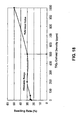
- FIG. 18 shows a technique of determining an upper limit of the density of the TiO 2 colloid (ppm) in view of the corrosion resistance. That is, the relationship between the TiO 2 colloid density (ppm) and the coating-film F swelling rate (%) after 60 cycles of the CCTs in FIG. 17 is plotted in FIG. 18 , and the upper limit of the TiO 2 colloid density (ppm) is determined based on a coating-film swelling rate of 30 (%) which is used as an allowable limit (reference value) of the corrosion resistance. In this case, the coating-film swelling rate of 30 (%) is used as the allowable limit (reference value) of the corrosion resistance. This is based on the following reason.
- the density of the TiO 2 colloid in the solution in the adsorption process at the allowable limit of corrosion resistance is 500 ppm. That is, it is necessary to set the TiO 2 colloid density at 500 ppm or less in order to ensure the corrosion resistance. Meanwhile, with respect to a lower limit, it is necessary to set that at 10 ppm or more in order to ensure the coating-film thickness.
- FIGS. 19 through 25 show a second embodiment of the present invention.
- the n-type ZnO as n-type semiconductor fine particles was used as the electron releasing substance to be adsorbadsorbed in the adsorption process, and it was contained in the ZrO 2 film 21 through the chemical conversion process to make a developed film of the present embodiment.
- the content ratio of the n-type ZnO to the ZrO 2 film 21 was 5.6 mass %
- the n-type ZnO had the following composition and characteristics:
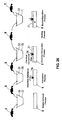
- the coating-film thickness characteristic (electrodeposition coatability) of the ZrO 2 film containing the n-type ZnO became similar to that of the zinc phosphate film 1. This is because it can be considered that in case the ZrO 2 film 21 containing the n-type ZnO was used as a chemical conversion film, the number of free electrons (local electrical-conductive areas) was increased during the voltage application to promote the deposition of the coating film (resin) F onto the surface of the steel sheet S, as shown in a conceptual diagram of FIG. 20 .
- an applied voltage to increase the number of free electrons is preferably set at a value greater than a corrosion potential (e.g., about 1 V).
- a corrosion potential e.g., about 1 V.
- reference character P denotes a coating material having water solubility given by acid.
- FIGS. 21 through 23 show results of measurement of a current density distribution on a surface of each of the ZrO 2 film 21 (not containing the n-type ZnO) and the ZrO 2 film 21 containing the above-described n-type ZnO by using a scanning vibrating electrode technique (SVET).
- FIG. 21 is a graph showing the current density distribution during non-voltage application, in each of the conventional ZrO 2 film and the ZrO 2 film containing the n-type ZnO. In this case, no current was detected in either measurement.
- FIG. 22 is a graph showing the current density distribution during voltage (1 V) application, in the ZrO 2 film. In this case, no current was detected, either.
- FIG. 23 is a graph showing the current density distribution during voltage (1 V) application, in the ZrO 2 film 21 containing the n-type ZnO. In this case, a current was detected as shown in FIG. 23 . This verified that the n-type ZnO contributes to an increase in the number of free electrons (local electrical-conductive areas), so as to promote deposition of a coating film F.
- FIG. 24 is a table showing an influence of a content ratio of the n-type ZnO (semiconductor fine particles) to the ZrO 2 film containing the n-type ZnO, on the film thickness (electrodeposition coatability) of the coating film and the corrosion resistance.
- the film thickness (electrodeposition coatability) of the coating film becomes greater (thicker) along with an increase in amount (mass %) of the n-type ZnO, and a problem about the corrosion resistance occurs when the amount (mass %) of the n-type ZnO is increased up to a specified value or more although the corrosion resistance is in an allowable range when the amount is less than the specified value.
- the corrosion resistance was evaluated based on measurement of the swelling rate (%) of the coating film F after 60 cycles of cyclic corrosion tests (CCTs) (1 cycle of the CCT is approximately equal to 3 cycles of JIS K5600-7-9 cycle A).
- FIG. 25 shows a technique of determining an upper limit of the amount (mass %) of the n-type ZnO in view of the corrosion resistance.
- the relationship between the amount (mass %) of the n-type ZnO and the coating-film swelling rate (%) of the coating film F after 60 cycles of the CCTs in FIG. 24 is plotted in FIG. 25 , and an upper limit of the amount (mass %) of the n-type ZnO is determined based on a coating-film swelling rate of 30 (%) which is used as an allowable limit (reference value) of the corrosion resistance.
- a coating-film swelling rate of 30 (%) is used as an allowable limit (reference value) of the corrosion resistance. This is based on the following reason.
- a 12-year warranty against a rust hole of an outer panel of a vehicle body becomes mainstream, and it has been confirmed by past records that the warranty is satisfied when the coating-film swelling rate is less than 30 (%).
- the amount (mass %) of the n-type ZnO at the allowable limit of the corrosion resistance is 8.2 mass %. That is, it is necessary to set the amount of the n-type ZnO at 8.2 mass % or less in order to ensure the corrosion resistance.
- a third embodiment which is shown in FIG. 26 , shows manufacturing processes, in which a doping treatment of an electron releasing-related substance which is adsorbed in the adsorption process is applied to a chemical conversion film before the electrodeposition coating process and thereby the chemical conversion film is formed on the n-type semiconductor.
- an electron releasing-related substance which has a greater electric charge number than the chemical conversion film (Zr) was used and it was adsorbed into the vehicle body W in the adsorption process. Then, the vehicle body W was heated (anneal treatment) in a heating process which is before the electrodeposition coating process and after the chemical conversion process, so that a doping treatment of the electron releasing substance was applied to the chemical conversion film.
- Specific manufacturing conditions were as follows:
- FIG. 27 is a process diagram showing manufacturing processes according to a fourth embodiment of the present invention.
- the same portions as those in the above-described manufacturing processes of the first embodiment which is shown in FIG. 1 are denoted by the same reference characters, and detailed description of those are omitted here.
- an adsorption (attachment) process is provided after the grease removal process (where the vehicle body W is immersed in the grease removing solution 38 contained in the grease removal tank 37 for a period of time 180 sec., for example, to remove grease, dust and the like which are attached onto the vehicle body W ) and before the chemical conversion process.
- an electrically conductive substance 34' is adsorbed in (attached onto) the vehicle body W.
- the reason for this is to form an uneven surface of the vehicle body W through the adsorption treatment of the electrically conductive substance 34' so that the chemical conversion film 21 formed on the vehicle body W in the subsequent chemical conversion process can have a large number of local low-resistance areas (i.e., thin film portions (superior electrical-conductive areas).
- a metal of Cu i.e., copper
- the metal Cu exists in an ion state in a treatment solution 35' contained in the adsorption treatment tank 36 (e.g., a copper sulfate solution is used as the treatment solution).
- the density of Cu ion of the treatment solution 35' is set at 5 to 500 ppm, having pH 2 to 5 and a solution temperature (bath tempt.) of 10 to 40°C, in view of the coating-film thickness (electrodeposition characteristic) and corrosion resistance.
- the vehicle body W is immersed in the treatment solution 35' as the attachment treatment.
- Fe as a component of the vehicle body W is ionized to release electrons, and the released electrons are combined with Cu 2+ in the treatment solution 35', resulting in deposition of Cu on the surface of the vehicle body W, which is expressed by the following reaction formula 6.
- an immersion period of time is set at about 10 to 600 sec. (30 sec. in the present embodiment) in view of the deposition (adsorption) of Cu.
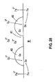
- the surface of the vehicle body W becomes uneven by the deposition of Cu as shown in FIG. 28 (conceptual diagram) (the height from a bottom face of a concave portion 41 (the surface of the vehicle body W) to a top face of a convex portion 40 is about some nm).
- This uneven state of the surface of the vehicle body W is caused by local difference in an etching reaction (deposition reaction) due to differences in a degree of surface oxidization and a state of electrons.
- Cu is deposited mainly at regions of the surface of the vehicle body W where the etching reaction occurs easily, thereby forming the convex portions 40 at the regions.
- the convex portions 40 comprised of the deposited Cu may have a circular shape, an oval shape, or their combined shape. Between the convex portions 40 are formed the concave portions 41, where the surface of the vehicle body W (bottom face of the concave portions 41) is exposed to the outside.
- a metal connection occurs between each of the deposited Cu or the deposited Cu and Fe (the component of the vehicle body W), so that the deposited Cu may not come off the vehicle body W even if the vehicle body W is immersed in the tank 33 in the chemical conversion process.
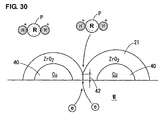
- the electrons from the ionization of the component (Fe) of the vehicle body W move to the convex portions 40 with Cu having a higher electrical potential, and ZrO 2 is deposited positively on the convex portions 40 based on the above-described electrons.
- the component (Fe) of the vehicle body W is exposed at the concave portions 41 between the adjacent convex portions 40, where ZrO 2 are not deposited very much (the electrical potential of Fe is smaller than that of Cu).
- the film thickness of ZrO 2 of the concave portions 41 is smaller than (thinner) than that of the other portion (convex portions 40), and thin film portions 42 are formed.
- the thin film portions 42 of the chemical conversion film 21 become the local low-resistance areas, so that the deposition of the coating film can be promoted by these thin film portions 42 as electrical-conductive areas during the voltage application in the electrodeposition coating process. Accordingly, the electrodeposition coatability at the low voltage-applied regions can be improved.
- the coating-film thickness characteristic (electrodeposition characteristic) of the chemical conversion film (ZrO 2 film which is formed on Cu deposited on the surface of the vehicle body W), which has been finally formed through the adsorption process and the chemical conversion process, becomes similar to that of the crystalline zinc phosphate film 1.
- the eutrophication can be prevented and the production of waste sludge associated can be suppressed, and also the excellent corrosion resistance and electrodeposition coatability can be obtained.
- the basic functions such as the corrosion resistance, are ensured by the properties of the chemical conversion film 21 occupying its most part (with an extremely small amount of deposited component 34'), and an excessive deposition of the coating film F onto the outer panel of the vehicle body W adjacent to the anode is suppressed by a relative decrease of the ratio of the chemical conversion component based on containment of Cu in the chemical conversion film 21.
- a large number of local low-resistance areas i.e., thin film portions 42, superior electrical-conductive portions
- the electrodeposition coatability on the inner panel of the vehicle body W far from the anode in the low voltage-applied region can be improved.
- the film thickness of the coating film at the portion of the workpiece adjacent to the anode which belongs to the high voltage-applied region becomes fairly greater than that of the case of the zinc phosphate film
- the film thickness of the coating film at the portion of the workpiece far from the anode which belongs to the low voltage-applied region becomes considerably smaller than that of the case of the zinc phosphate film
- the thickness of the film may increase, so that the deposition of the coating film may not occur unless a voltage to initiate the deposition of the coating film is increased further.
- the supplied electrons increase during the voltage application (the number of electrical-conductive areas increase) at the thin film portions 42. Consequently, the concentration of the electric charges in the respective low-resistance areas 22 can be avoided.
- the above-described problem the coating-film thickness characteristic of the ZrO 2 film 21 becomes similar to that of the crystalline zinc phosphate film 1) can be avoided.
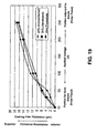
- FIG. 31 shows a coating-film thickness characteristic of the ZrO 2 film formed on the vehicle body W through the deposition of Cu in the adsorption process for the purpose of supporting the above-described contents.
- a test sample used a vehicle body which was immersed in the treatment solution 35' containing the Cu ion in the adsorption process, and then it was immersed in the chemical treatment agent 32 in the chemical conversion process.
- the specific test conditions were as follows:
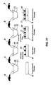
- the coating-film thickness characteristic (electrodeposition coatability) of the ZrO 2 film 21 formed on the vehicle body W through the deposition of Cu in the adsorption process became similar to that of the zinc phosphate film 1. This is because it can be considered that the chemical conversion film 21 forms the thin film portions 42 with the concave portions 41 formed between the adjacent convex portions 40 of Cu, and these thin film portions 42 become the local low-resistance areas (superior electrical-conductive areas), thereby promoting the deposition of the coating film (resin) F, as shown in a conceptual diagram of FIG. 30 .
- an applied voltage to increase the number of electrical-conductive areas is preferably set at a value greater than a corrosion potential (e.g., about 1 V).
- a corrosion potential e.g., about 1 V.
- reference character P denotes a coating material having water solubility given by acid.
- FIG. 32 is a table showing an influence of the density of the Cu ion in the treatment solution 35' in the adsorption process on the coating-film thickness (electrodeposition coatability) and the corrosion resistance.
- the coating-film thickness becomes greater (thicker) along with an increase in the density of the Cu ion and then turns to decrease when reaching a specified value, and a problem about the corrosion resistance occurs when the density (ppm) of the Cu ion is increased up to a specified value or more although the corrosion resistance is in an allowable range when the amount is less than the specified value.
- the immersion period of time of the vehicle body W in the adsorption treatment tank 36 was 30 sec.
- the temperature of the treatment agent in the adsorption treatment tank (bath tempt.) was 30°C
- pH of the treatment solution was 3, and the conditions used in the test shown in FIG. 31 were used as the conditions of the chemical conversion process.
- the corrosion resistance was evaluated based on measurement of a swelling rate (%) of the coating film F after 60 cycles of cyclic corrosion tests (CCTs) (1 cycle of the CCT is approximately equal to 3 cycles of JIS K5600-7-9 cycle A).
- FIG. 33 shows a technique of determining an upper limit of the density of the Cu ion (ppm) in the treatment solution 35' in view of the corrosion resistance. That is, the relationship between the Cu ion density (ppm) and the coating-film F swelling rate (%) after 60 cycles of the CCTs in FIG. 32 is plotted in FIG. 33 , and the upper limit of the Cu ion density (ppm) in the treatment solution is determined based on a coating-film swelling rate of 30 (%) which is used as an allowable limit (reference value) of the corrosion resistance. In this case, the coating-film swelling rate of 30 (%) is used as the allowable limit (reference value) of the corrosion resistance. This is based on the following reason.
- the density of the Cu ion in the treatment solution in the adsorption process at the allowable limit of corrosion resistance is 500 ppm. That is, it is necessary to set the Cu ion density in the treatment solution at 500 ppm or less in order to ensure the corrosion resistance. Meanwhile, with respect to a lower limit, is necessary to set that at 5ppm or more in order to ensure the coating-film thickness.
- the electron releasing-related substance or the electrically conductive substance may be attached onto the vehicle body (workpiece to be coated) through any other treatment using spray, deposition, thermal spraying or the like instead of the immersion treatment.
Landscapes
- Chemical & Material Sciences (AREA)
- Metallurgy (AREA)
- Chemical Kinetics & Catalysis (AREA)
- Engineering & Computer Science (AREA)
- Materials Engineering (AREA)
- Organic Chemistry (AREA)
- Mechanical Engineering (AREA)
- General Chemical & Material Sciences (AREA)
- Electrochemistry (AREA)
- Chemical Treatment Of Metals (AREA)
- Other Surface Treatments For Metallic Materials (AREA)
- Application Of Or Painting With Fluid Materials (AREA)
- Paints Or Removers (AREA)
Applications Claiming Priority (2)
| Application Number | Priority Date | Filing Date | Title |
|---|---|---|---|
| JP2009203999A JP5526664B2 (ja) | 2009-09-03 | 2009-09-03 | 金属部材の表面処理方法 |
| JP2009245084A JP5163622B2 (ja) | 2009-10-26 | 2009-10-26 | 金属部材の表面処理方法 |
Publications (3)
| Publication Number | Publication Date |
|---|---|
| EP2302096A2 true EP2302096A2 (de) | 2011-03-30 |
| EP2302096A3 EP2302096A3 (de) | 2012-06-13 |
| EP2302096B1 EP2302096B1 (de) | 2019-06-26 |
Family
ID=43259840
Family Applications (1)
| Application Number | Title | Priority Date | Filing Date |
|---|---|---|---|
| EP10009092.7A Not-in-force EP2302096B1 (de) | 2009-09-03 | 2010-09-01 | Verfahren zur Behandlung einer metallischen Oberfläche |
Country Status (3)
| Country | Link |
|---|---|
| US (1) | US8506728B2 (de) |
| EP (1) | EP2302096B1 (de) |
| CN (1) | CN102011111B (de) |
Cited By (2)
| Publication number | Priority date | Publication date | Assignee | Title |
|---|---|---|---|---|
| US10125424B2 (en) | 2012-08-29 | 2018-11-13 | Ppg Industries Ohio, Inc. | Zirconium pretreatment compositions containing molybdenum, associated methods for treating metal substrates, and related coated metal substrates |
| US10400337B2 (en) | 2012-08-29 | 2019-09-03 | Ppg Industries Ohio, Inc. | Zirconium pretreatment compositions containing lithium, associated methods for treating metal substrates, and related coated metal substrates |
Families Citing this family (8)
| Publication number | Priority date | Publication date | Assignee | Title |
|---|---|---|---|---|
| JP1516438S (de) | 2013-06-28 | 2015-02-02 | ||
| USD733645S1 (en) | 2013-06-28 | 2015-07-07 | Dow Global Technologies Llc | Corner connector for a photovoltaic module frame |
| USD710793S1 (en) | 2013-06-28 | 2014-08-12 | Dow Global Technologies Llc | Anchor block for photovoltaic module |
| USD710298S1 (en) | 2013-06-28 | 2014-08-05 | Dow Global Technologies Llc | Photovoltaic module assembly |
| USD710792S1 (en) | 2013-06-28 | 2014-08-12 | Dow Global Technologies Llc | Angle corner connector for photovoltaic module frame |
| USD747262S1 (en) | 2013-06-28 | 2016-01-12 | Dow Global Technologies Llc | Photovoltaic back panel |
| CN104407683A (zh) * | 2014-11-05 | 2015-03-11 | 曙光信息产业(北京)有限公司 | Cpu外壳以及cpu外壳的加工方法 |
| US11518960B2 (en) | 2016-08-24 | 2022-12-06 | Ppg Industries Ohio, Inc. | Alkaline molybdenum cation and phosphonate-containing cleaning composition |
Citations (1)
| Publication number | Priority date | Publication date | Assignee | Title |
|---|---|---|---|---|
| US7510612B2 (en) | 2002-12-24 | 2009-03-31 | Nippon Paint Co., Ltd. | Chemical conversion coating agent and surface-treated metal |
Family Cites Families (19)
| Publication number | Priority date | Publication date | Assignee | Title |
|---|---|---|---|---|
| GB1293884A (en) | 1971-01-06 | 1972-10-25 | Amchem Prod | Improvements in processes for applying paint by electrophoretic deposition onto ferrous surfaces |
| JPS61257481A (ja) | 1985-05-10 | 1986-11-14 | Nippon Parkerizing Co Ltd | りん酸塩皮膜化成処理用水性表面調整液 |
| JPS62284087A (ja) | 1986-06-03 | 1987-12-09 | Kawasaki Steel Corp | 塗膜密着性に優れた表面処理鋼板およびその製造方法 |
| DE19511573A1 (de) | 1995-03-29 | 1996-10-02 | Henkel Kgaa | Verfahren zur Phosphatierung mit metallhaltiger Nachspülung |
| JP3967796B2 (ja) | 1997-08-18 | 2007-08-29 | 新日本製鐵株式会社 | 表面処理金属材料 |
| JP3410910B2 (ja) | 1996-10-11 | 2003-05-26 | スカイアルミニウム株式会社 | リン酸塩処理用アルミニウム材およびその表面処理方法 |
| JPH10140371A (ja) | 1996-11-08 | 1998-05-26 | Sky Alum Co Ltd | 燐酸塩処理用アルミニウム板及び燐酸塩処理方法 |
| US6214132B1 (en) | 1997-03-07 | 2001-04-10 | Henkel Corporation | Conditioning metal surfaces prior to phosphate conversion coating |
| JP3451334B2 (ja) * | 1997-03-07 | 2003-09-29 | 日本パーカライジング株式会社 | 金属のりん酸塩皮膜化成処理前の表面調整用前処理液及び表面調整方法 |
| DE19913242C2 (de) * | 1999-03-24 | 2001-09-27 | Electro Chem Eng Gmbh | Chemisch passivierter Gegenstand aus Magnesium oder seinen Legierungen, Verfahren zur Herstellung und seine Verwendung |
| JP2002060960A (ja) | 2000-08-23 | 2002-02-28 | Nisshin Steel Co Ltd | 色調安定性に優れた黒色化亜鉛系めっき鋼板の製造方法 |
| JP2007039765A (ja) | 2005-08-04 | 2007-02-15 | Ishihara Sangyo Kaisha Ltd | 金属微粒子の製造方法 |
| JP2007204835A (ja) | 2006-02-03 | 2007-08-16 | Nippon Paint Co Ltd | 表面調整用組成物及び表面調整方法 |
| EP2007920B1 (de) | 2006-04-07 | 2013-10-02 | Chemetall GmbH | Oberflächenkonditionierungszusammensetzung, verfahren zu ihrer herstellung und verfahren zur oberflächenkonditionierung |
| JP2007224426A (ja) | 2007-06-11 | 2007-09-06 | Nippon Parkerizing Co Ltd | 金属のりん酸塩皮膜化成処理前の表面調整用前処理液及び表面調整方法 |
| CN101809200A (zh) | 2007-09-27 | 2010-08-18 | 日本油漆株式会社 | 表面处理金属材料和金属涂装物的制造方法 |
| US9574093B2 (en) | 2007-09-28 | 2017-02-21 | Ppg Industries Ohio, Inc. | Methods for coating a metal substrate and related coated metal substrates |
| JP2009209407A (ja) | 2008-03-04 | 2009-09-17 | Mazda Motor Corp | 化成処理剤及び表面処理金属 |
| CN104790014B (zh) | 2008-05-29 | 2017-08-25 | 日本帕卡濑精株式会社 | 带有铋被膜的金属材料及其制造方法、在其中所使用的表面处理液以及阳离子电沉积涂覆金属材料及其制造方法 |
-
2010
- 2010-07-19 US US12/839,034 patent/US8506728B2/en not_active Expired - Fee Related
- 2010-08-31 CN CN201010276050.4A patent/CN102011111B/zh not_active Expired - Fee Related
- 2010-09-01 EP EP10009092.7A patent/EP2302096B1/de not_active Not-in-force
Patent Citations (1)
| Publication number | Priority date | Publication date | Assignee | Title |
|---|---|---|---|---|
| US7510612B2 (en) | 2002-12-24 | 2009-03-31 | Nippon Paint Co., Ltd. | Chemical conversion coating agent and surface-treated metal |
Cited By (3)
| Publication number | Priority date | Publication date | Assignee | Title |
|---|---|---|---|---|
| US10125424B2 (en) | 2012-08-29 | 2018-11-13 | Ppg Industries Ohio, Inc. | Zirconium pretreatment compositions containing molybdenum, associated methods for treating metal substrates, and related coated metal substrates |
| US10400337B2 (en) | 2012-08-29 | 2019-09-03 | Ppg Industries Ohio, Inc. | Zirconium pretreatment compositions containing lithium, associated methods for treating metal substrates, and related coated metal substrates |
| US10920324B2 (en) | 2012-08-29 | 2021-02-16 | Ppg Industries Ohio, Inc. | Zirconium pretreatment compositions containing molybdenum, associated methods for treating metal substrates, and related coated metal substrates |
Also Published As
| Publication number | Publication date |
|---|---|
| EP2302096B1 (de) | 2019-06-26 |
| EP2302096A3 (de) | 2012-06-13 |
| CN102011111A (zh) | 2011-04-13 |
| CN102011111B (zh) | 2015-01-14 |
| US8506728B2 (en) | 2013-08-13 |
| US20110048584A1 (en) | 2011-03-03 |
Similar Documents
| Publication | Publication Date | Title |
|---|---|---|
| EP2302096A2 (de) | Verfahren zur Behandlung einer metallischen Oberfläche | |
| JP2018135569A (ja) | Snめっき鋼板及びSnめっき鋼板の製造方法 | |
| GB2342099A (en) | Electrode for chromium plating | |
| Li et al. | Preparation and characterization of superhydrophobic composite coatings on a magnesium–lithium alloy | |
| KR20050044602A (ko) | 금속 산화물 및/또는 금속 수산화물 피복 금속재료와 그제조방법 | |
| JP5671210B2 (ja) | 金属表面処理方法 | |
| EP2100986A1 (de) | Chemisches Umwandlungsbehandlungsmittel und oberflächenbehandeltes Metallmaterial | |
| WO2018042980A1 (ja) | 表面処理鋼板、有機樹脂被覆鋼板、及びこれらを用いた容器 | |
| KR20180132120A (ko) | Sn계 합금 도금 강판 | |
| EP3786319B1 (de) | Verfahren zur herstellung eines oberflächenbehandelten stahlblechs | |
| JP2004060052A (ja) | Si含有化成皮膜を有する錫系めっき鋼板の製造方法 | |
| JP4400372B2 (ja) | 半田付け性、耐食性および耐ホイスカー性に優れるSn系めっき鋼板およびその製造方法 | |
| Ivanova et al. | Electrodeposition of metal molybdenum from electrolytes containing hydrofluoric acid | |
| JP6852454B2 (ja) | Sn系合金めっき鋼板及びSn系合金めっき鋼板の製造方法 | |
| JP5163622B2 (ja) | 金属部材の表面処理方法 | |
| JP5526664B2 (ja) | 金属部材の表面処理方法 | |
| JP6111058B2 (ja) | 燃料電池用セパレータ、燃料電池セル、燃料電池スタック、および燃料電池用セパレータの製造方法 | |
| US9309602B2 (en) | Electrolytic iron metallizing of zinc surfaces | |
| CN115720562A (zh) | 表面处理钢板、金属容器和表面处理钢板的制造方法 | |
| JP6066030B2 (ja) | 容器用鋼板及び容器用鋼板の製造方法 | |
| JP5092332B2 (ja) | 表面処理鋼板およびその製造方法 | |
| JP4321123B2 (ja) | 半田付け性に優れる錫めっき鋼板 | |
| JPH032391A (ja) | 化成処理性と塗装後性能に優れた亜鉛系めっき鋼板の製造方法 | |
| EP1369502A1 (de) | Mittel zur Elektrobeschichtung | |
| JPH08296015A (ja) | プレス性、化成処理性、電着塗装性に優れた合金化溶融亜鉛めっき鋼板 |
Legal Events
| Date | Code | Title | Description |
|---|---|---|---|
| PUAI | Public reference made under article 153(3) epc to a published international application that has entered the european phase |
Free format text: ORIGINAL CODE: 0009012 |
|
| AK | Designated contracting states |
Kind code of ref document: A2 Designated state(s): AL AT BE BG CH CY CZ DE DK EE ES FI FR GB GR HR HU IE IS IT LI LT LU LV MC MK MT NL NO PL PT RO SE SI SK SM TR |
|
| AX | Request for extension of the european patent |
Extension state: BA ME RS |
|
| RIC1 | Information provided on ipc code assigned before grant |
Ipc: B05D 7/00 20060101ALI20120130BHEP Ipc: C25D 5/34 20060101ALI20120130BHEP Ipc: C23C 22/78 20060101ALI20120130BHEP Ipc: B05D 7/14 20060101ALI20120130BHEP Ipc: C23C 22/00 20060101AFI20120130BHEP Ipc: C23C 22/83 20060101ALI20120130BHEP |
|
| PUAL | Search report despatched |
Free format text: ORIGINAL CODE: 0009013 |
|
| AK | Designated contracting states |
Kind code of ref document: A3 Designated state(s): AL AT BE BG CH CY CZ DE DK EE ES FI FR GB GR HR HU IE IS IT LI LT LU LV MC MK MT NL NO PL PT RO SE SI SK SM TR |
|
| AX | Request for extension of the european patent |
Extension state: BA ME RS |
|
| RIC1 | Information provided on ipc code assigned before grant |
Ipc: C23C 22/00 20060101AFI20120508BHEP Ipc: B05D 7/00 20060101ALI20120508BHEP Ipc: C23C 22/83 20060101ALI20120508BHEP Ipc: B05D 7/14 20060101ALI20120508BHEP Ipc: C25D 5/34 20060101ALI20120508BHEP Ipc: C23C 22/78 20060101ALI20120508BHEP |
|
| 17P | Request for examination filed |
Effective date: 20121122 |
|
| 17Q | First examination report despatched |
Effective date: 20160217 |
|
| GRAP | Despatch of communication of intention to grant a patent |
Free format text: ORIGINAL CODE: EPIDOSNIGR1 |
|
| STAA | Information on the status of an ep patent application or granted ep patent |
Free format text: STATUS: GRANT OF PATENT IS INTENDED |
|
| INTG | Intention to grant announced |
Effective date: 20190115 |
|
| RIN1 | Information on inventor provided before grant (corrected) |
Inventor name: KATSURA, DAIJI Inventor name: SHIGENAGA, TSUTOMU |
|
| GRAS | Grant fee paid |
Free format text: ORIGINAL CODE: EPIDOSNIGR3 |
|
| GRAA | (expected) grant |
Free format text: ORIGINAL CODE: 0009210 |
|
| STAA | Information on the status of an ep patent application or granted ep patent |
Free format text: STATUS: THE PATENT HAS BEEN GRANTED |
|
| RIN1 | Information on inventor provided before grant (corrected) |
Inventor name: KATSURA, DAIJI Inventor name: SHIGENAGA, TSUTOMU |
|
| AK | Designated contracting states |
Kind code of ref document: B1 Designated state(s): AL AT BE BG CH CY CZ DE DK EE ES FI FR GB GR HR HU IE IS IT LI LT LU LV MC MK MT NL NO PL PT RO SE SI SK SM TR |
|
| REG | Reference to a national code |
Ref country code: GB Ref legal event code: FG4D |
|
| REG | Reference to a national code |
Ref country code: CH Ref legal event code: EP |
|
| REG | Reference to a national code |
Ref country code: AT Ref legal event code: REF Ref document number: 1148363 Country of ref document: AT Kind code of ref document: T Effective date: 20190715 |
|
| REG | Reference to a national code |
Ref country code: DE Ref legal event code: R096 Ref document number: 602010059639 Country of ref document: DE |
|
| REG | Reference to a national code |
Ref country code: IE Ref legal event code: FG4D |
|
| REG | Reference to a national code |
Ref country code: NL Ref legal event code: MP Effective date: 20190626 |
|
| PG25 | Lapsed in a contracting state [announced via postgrant information from national office to epo] |
Ref country code: SE Free format text: LAPSE BECAUSE OF FAILURE TO SUBMIT A TRANSLATION OF THE DESCRIPTION OR TO PAY THE FEE WITHIN THE PRESCRIBED TIME-LIMIT Effective date: 20190626 Ref country code: AL Free format text: LAPSE BECAUSE OF FAILURE TO SUBMIT A TRANSLATION OF THE DESCRIPTION OR TO PAY THE FEE WITHIN THE PRESCRIBED TIME-LIMIT Effective date: 20190626 Ref country code: HR Free format text: LAPSE BECAUSE OF FAILURE TO SUBMIT A TRANSLATION OF THE DESCRIPTION OR TO PAY THE FEE WITHIN THE PRESCRIBED TIME-LIMIT Effective date: 20190626 Ref country code: LT Free format text: LAPSE BECAUSE OF FAILURE TO SUBMIT A TRANSLATION OF THE DESCRIPTION OR TO PAY THE FEE WITHIN THE PRESCRIBED TIME-LIMIT Effective date: 20190626 Ref country code: NO Free format text: LAPSE BECAUSE OF FAILURE TO SUBMIT A TRANSLATION OF THE DESCRIPTION OR TO PAY THE FEE WITHIN THE PRESCRIBED TIME-LIMIT Effective date: 20190926 Ref country code: FI Free format text: LAPSE BECAUSE OF FAILURE TO SUBMIT A TRANSLATION OF THE DESCRIPTION OR TO PAY THE FEE WITHIN THE PRESCRIBED TIME-LIMIT Effective date: 20190626 |
|
| REG | Reference to a national code |
Ref country code: LT Ref legal event code: MG4D |
|
| PG25 | Lapsed in a contracting state [announced via postgrant information from national office to epo] |
Ref country code: GR Free format text: LAPSE BECAUSE OF FAILURE TO SUBMIT A TRANSLATION OF THE DESCRIPTION OR TO PAY THE FEE WITHIN THE PRESCRIBED TIME-LIMIT Effective date: 20190927 Ref country code: BG Free format text: LAPSE BECAUSE OF FAILURE TO SUBMIT A TRANSLATION OF THE DESCRIPTION OR TO PAY THE FEE WITHIN THE PRESCRIBED TIME-LIMIT Effective date: 20190926 Ref country code: LV Free format text: LAPSE BECAUSE OF FAILURE TO SUBMIT A TRANSLATION OF THE DESCRIPTION OR TO PAY THE FEE WITHIN THE PRESCRIBED TIME-LIMIT Effective date: 20190626 |
|
| REG | Reference to a national code |
Ref country code: AT Ref legal event code: MK05 Ref document number: 1148363 Country of ref document: AT Kind code of ref document: T Effective date: 20190626 |
|
| PG25 | Lapsed in a contracting state [announced via postgrant information from national office to epo] |
Ref country code: PT Free format text: LAPSE BECAUSE OF FAILURE TO SUBMIT A TRANSLATION OF THE DESCRIPTION OR TO PAY THE FEE WITHIN THE PRESCRIBED TIME-LIMIT Effective date: 20191028 Ref country code: SK Free format text: LAPSE BECAUSE OF FAILURE TO SUBMIT A TRANSLATION OF THE DESCRIPTION OR TO PAY THE FEE WITHIN THE PRESCRIBED TIME-LIMIT Effective date: 20190626 Ref country code: CZ Free format text: LAPSE BECAUSE OF FAILURE TO SUBMIT A TRANSLATION OF THE DESCRIPTION OR TO PAY THE FEE WITHIN THE PRESCRIBED TIME-LIMIT Effective date: 20190626 Ref country code: AT Free format text: LAPSE BECAUSE OF FAILURE TO SUBMIT A TRANSLATION OF THE DESCRIPTION OR TO PAY THE FEE WITHIN THE PRESCRIBED TIME-LIMIT Effective date: 20190626 Ref country code: EE Free format text: LAPSE BECAUSE OF FAILURE TO SUBMIT A TRANSLATION OF THE DESCRIPTION OR TO PAY THE FEE WITHIN THE PRESCRIBED TIME-LIMIT Effective date: 20190626 Ref country code: NL Free format text: LAPSE BECAUSE OF FAILURE TO SUBMIT A TRANSLATION OF THE DESCRIPTION OR TO PAY THE FEE WITHIN THE PRESCRIBED TIME-LIMIT Effective date: 20190626 Ref country code: RO Free format text: LAPSE BECAUSE OF FAILURE TO SUBMIT A TRANSLATION OF THE DESCRIPTION OR TO PAY THE FEE WITHIN THE PRESCRIBED TIME-LIMIT Effective date: 20190626 |
|
| PG25 | Lapsed in a contracting state [announced via postgrant information from national office to epo] |
Ref country code: ES Free format text: LAPSE BECAUSE OF FAILURE TO SUBMIT A TRANSLATION OF THE DESCRIPTION OR TO PAY THE FEE WITHIN THE PRESCRIBED TIME-LIMIT Effective date: 20190626 Ref country code: IS Free format text: LAPSE BECAUSE OF FAILURE TO SUBMIT A TRANSLATION OF THE DESCRIPTION OR TO PAY THE FEE WITHIN THE PRESCRIBED TIME-LIMIT Effective date: 20191026 Ref country code: SM Free format text: LAPSE BECAUSE OF FAILURE TO SUBMIT A TRANSLATION OF THE DESCRIPTION OR TO PAY THE FEE WITHIN THE PRESCRIBED TIME-LIMIT Effective date: 20190626 Ref country code: IT Free format text: LAPSE BECAUSE OF FAILURE TO SUBMIT A TRANSLATION OF THE DESCRIPTION OR TO PAY THE FEE WITHIN THE PRESCRIBED TIME-LIMIT Effective date: 20190626 |
|
| PG25 | Lapsed in a contracting state [announced via postgrant information from national office to epo] |
Ref country code: TR Free format text: LAPSE BECAUSE OF FAILURE TO SUBMIT A TRANSLATION OF THE DESCRIPTION OR TO PAY THE FEE WITHIN THE PRESCRIBED TIME-LIMIT Effective date: 20190626 |
|
| REG | Reference to a national code |
Ref country code: DE Ref legal event code: R119 Ref document number: 602010059639 Country of ref document: DE |
|
| PG25 | Lapsed in a contracting state [announced via postgrant information from national office to epo] |
Ref country code: PL Free format text: LAPSE BECAUSE OF FAILURE TO SUBMIT A TRANSLATION OF THE DESCRIPTION OR TO PAY THE FEE WITHIN THE PRESCRIBED TIME-LIMIT Effective date: 20190626 Ref country code: DK Free format text: LAPSE BECAUSE OF FAILURE TO SUBMIT A TRANSLATION OF THE DESCRIPTION OR TO PAY THE FEE WITHIN THE PRESCRIBED TIME-LIMIT Effective date: 20190626 |
|
| PG25 | Lapsed in a contracting state [announced via postgrant information from national office to epo] |
Ref country code: MC Free format text: LAPSE BECAUSE OF FAILURE TO SUBMIT A TRANSLATION OF THE DESCRIPTION OR TO PAY THE FEE WITHIN THE PRESCRIBED TIME-LIMIT Effective date: 20190626 Ref country code: IS Free format text: LAPSE BECAUSE OF FAILURE TO SUBMIT A TRANSLATION OF THE DESCRIPTION OR TO PAY THE FEE WITHIN THE PRESCRIBED TIME-LIMIT Effective date: 20200224 |
|
| REG | Reference to a national code |
Ref country code: CH Ref legal event code: PL |
|
| PLBE | No opposition filed within time limit |
Free format text: ORIGINAL CODE: 0009261 |
|
| STAA | Information on the status of an ep patent application or granted ep patent |
Free format text: STATUS: NO OPPOSITION FILED WITHIN TIME LIMIT |
|
| PG2D | Information on lapse in contracting state deleted |
Ref country code: IS |
|
| PG25 | Lapsed in a contracting state [announced via postgrant information from national office to epo] |
Ref country code: LI Free format text: LAPSE BECAUSE OF NON-PAYMENT OF DUE FEES Effective date: 20190930 Ref country code: IE Free format text: LAPSE BECAUSE OF NON-PAYMENT OF DUE FEES Effective date: 20190901 Ref country code: LU Free format text: LAPSE BECAUSE OF NON-PAYMENT OF DUE FEES Effective date: 20190901 Ref country code: CH Free format text: LAPSE BECAUSE OF NON-PAYMENT OF DUE FEES Effective date: 20190930 Ref country code: DE Free format text: LAPSE BECAUSE OF NON-PAYMENT OF DUE FEES Effective date: 20200401 |
|
| 26N | No opposition filed |
Effective date: 20200603 |
|
| REG | Reference to a national code |
Ref country code: BE Ref legal event code: MM Effective date: 20190930 |
|
| PG25 | Lapsed in a contracting state [announced via postgrant information from national office to epo] |
Ref country code: BE Free format text: LAPSE BECAUSE OF NON-PAYMENT OF DUE FEES Effective date: 20190930 Ref country code: SI Free format text: LAPSE BECAUSE OF FAILURE TO SUBMIT A TRANSLATION OF THE DESCRIPTION OR TO PAY THE FEE WITHIN THE PRESCRIBED TIME-LIMIT Effective date: 20190626 |
|
| GBPC | Gb: european patent ceased through non-payment of renewal fee |
Effective date: 20190926 |
|
| PG25 | Lapsed in a contracting state [announced via postgrant information from national office to epo] |
Ref country code: FR Free format text: LAPSE BECAUSE OF NON-PAYMENT OF DUE FEES Effective date: 20190930 Ref country code: GB Free format text: LAPSE BECAUSE OF NON-PAYMENT OF DUE FEES Effective date: 20190926 |
|
| PG25 | Lapsed in a contracting state [announced via postgrant information from national office to epo] |
Ref country code: CY Free format text: LAPSE BECAUSE OF FAILURE TO SUBMIT A TRANSLATION OF THE DESCRIPTION OR TO PAY THE FEE WITHIN THE PRESCRIBED TIME-LIMIT Effective date: 20190626 |
|
| PG25 | Lapsed in a contracting state [announced via postgrant information from national office to epo] |
Ref country code: MT Free format text: LAPSE BECAUSE OF FAILURE TO SUBMIT A TRANSLATION OF THE DESCRIPTION OR TO PAY THE FEE WITHIN THE PRESCRIBED TIME-LIMIT Effective date: 20190626 Ref country code: HU Free format text: LAPSE BECAUSE OF FAILURE TO SUBMIT A TRANSLATION OF THE DESCRIPTION OR TO PAY THE FEE WITHIN THE PRESCRIBED TIME-LIMIT; INVALID AB INITIO Effective date: 20100901 |
|
| PG25 | Lapsed in a contracting state [announced via postgrant information from national office to epo] |
Ref country code: MK Free format text: LAPSE BECAUSE OF FAILURE TO SUBMIT A TRANSLATION OF THE DESCRIPTION OR TO PAY THE FEE WITHIN THE PRESCRIBED TIME-LIMIT Effective date: 20190626 |