EP2304200B1 - Vorrichtung zur eindosierung von kraftstoff - Google Patents
Vorrichtung zur eindosierung von kraftstoff Download PDFInfo
- Publication number
- EP2304200B1 EP2304200B1 EP09779499.4A EP09779499A EP2304200B1 EP 2304200 B1 EP2304200 B1 EP 2304200B1 EP 09779499 A EP09779499 A EP 09779499A EP 2304200 B1 EP2304200 B1 EP 2304200B1
- Authority
- EP
- European Patent Office
- Prior art keywords
- valve
- dosing
- metering unit
- fuel
- downstream
- Prior art date
- Legal status (The legal status is an assumption and is not a legal conclusion. Google has not performed a legal analysis and makes no representation as to the accuracy of the status listed.)
- Active
Links
Images

Classifications
-
- F—MECHANICAL ENGINEERING; LIGHTING; HEATING; WEAPONS; BLASTING
- F01—MACHINES OR ENGINES IN GENERAL; ENGINE PLANTS IN GENERAL; STEAM ENGINES
- F01N—GAS-FLOW SILENCERS OR EXHAUST APPARATUS FOR MACHINES OR ENGINES IN GENERAL; GAS-FLOW SILENCERS OR EXHAUST APPARATUS FOR INTERNAL-COMBUSTION ENGINES
- F01N3/00—Exhaust or silencing apparatus having means for purifying, rendering innocuous, or otherwise treating exhaust
- F01N3/08—Exhaust or silencing apparatus having means for purifying, rendering innocuous, or otherwise treating exhaust for rendering innocuous
- F01N3/10—Exhaust or silencing apparatus having means for purifying, rendering innocuous, or otherwise treating exhaust for rendering innocuous by thermal or catalytic conversion of noxious components of exhaust
- F01N3/24—Exhaust or silencing apparatus having means for purifying, rendering innocuous, or otherwise treating exhaust for rendering innocuous by thermal or catalytic conversion of noxious components of exhaust characterised by constructional aspects of converting apparatus
- F01N3/36—Arrangements for supply of additional fuel
-
- F—MECHANICAL ENGINEERING; LIGHTING; HEATING; WEAPONS; BLASTING
- F01—MACHINES OR ENGINES IN GENERAL; ENGINE PLANTS IN GENERAL; STEAM ENGINES
- F01N—GAS-FLOW SILENCERS OR EXHAUST APPARATUS FOR MACHINES OR ENGINES IN GENERAL; GAS-FLOW SILENCERS OR EXHAUST APPARATUS FOR INTERNAL-COMBUSTION ENGINES
- F01N3/00—Exhaust or silencing apparatus having means for purifying, rendering innocuous, or otherwise treating exhaust
- F01N3/02—Exhaust or silencing apparatus having means for purifying, rendering innocuous, or otherwise treating exhaust for cooling, or for removing solid constituents of, exhaust
- F01N3/021—Exhaust or silencing apparatus having means for purifying, rendering innocuous, or otherwise treating exhaust for cooling, or for removing solid constituents of, exhaust by means of filters
- F01N3/023—Exhaust or silencing apparatus having means for purifying, rendering innocuous, or otherwise treating exhaust for cooling, or for removing solid constituents of, exhaust by means of filters using means for regenerating the filters, e.g. by burning trapped particles
- F01N3/025—Exhaust or silencing apparatus having means for purifying, rendering innocuous, or otherwise treating exhaust for cooling, or for removing solid constituents of, exhaust by means of filters using means for regenerating the filters, e.g. by burning trapped particles using fuel burner or by adding fuel to exhaust
- F01N3/0253—Exhaust or silencing apparatus having means for purifying, rendering innocuous, or otherwise treating exhaust for cooling, or for removing solid constituents of, exhaust by means of filters using means for regenerating the filters, e.g. by burning trapped particles using fuel burner or by adding fuel to exhaust adding fuel to exhaust gases
-
- F—MECHANICAL ENGINEERING; LIGHTING; HEATING; WEAPONS; BLASTING
- F01—MACHINES OR ENGINES IN GENERAL; ENGINE PLANTS IN GENERAL; STEAM ENGINES
- F01N—GAS-FLOW SILENCERS OR EXHAUST APPARATUS FOR MACHINES OR ENGINES IN GENERAL; GAS-FLOW SILENCERS OR EXHAUST APPARATUS FOR INTERNAL-COMBUSTION ENGINES
- F01N3/00—Exhaust or silencing apparatus having means for purifying, rendering innocuous, or otherwise treating exhaust
- F01N3/02—Exhaust or silencing apparatus having means for purifying, rendering innocuous, or otherwise treating exhaust for cooling, or for removing solid constituents of, exhaust
- F01N3/021—Exhaust or silencing apparatus having means for purifying, rendering innocuous, or otherwise treating exhaust for cooling, or for removing solid constituents of, exhaust by means of filters
- F01N3/033—Exhaust or silencing apparatus having means for purifying, rendering innocuous, or otherwise treating exhaust for cooling, or for removing solid constituents of, exhaust by means of filters in combination with other devices
- F01N3/035—Exhaust or silencing apparatus having means for purifying, rendering innocuous, or otherwise treating exhaust for cooling, or for removing solid constituents of, exhaust by means of filters in combination with other devices with catalytic reactors
-
- F—MECHANICAL ENGINEERING; LIGHTING; HEATING; WEAPONS; BLASTING
- F01—MACHINES OR ENGINES IN GENERAL; ENGINE PLANTS IN GENERAL; STEAM ENGINES
- F01N—GAS-FLOW SILENCERS OR EXHAUST APPARATUS FOR MACHINES OR ENGINES IN GENERAL; GAS-FLOW SILENCERS OR EXHAUST APPARATUS FOR INTERNAL-COMBUSTION ENGINES
- F01N3/00—Exhaust or silencing apparatus having means for purifying, rendering innocuous, or otherwise treating exhaust
- F01N3/08—Exhaust or silencing apparatus having means for purifying, rendering innocuous, or otherwise treating exhaust for rendering innocuous
- F01N3/10—Exhaust or silencing apparatus having means for purifying, rendering innocuous, or otherwise treating exhaust for rendering innocuous by thermal or catalytic conversion of noxious components of exhaust
- F01N3/103—Oxidation catalysts for HC and CO only
-
- F—MECHANICAL ENGINEERING; LIGHTING; HEATING; WEAPONS; BLASTING
- F01—MACHINES OR ENGINES IN GENERAL; ENGINE PLANTS IN GENERAL; STEAM ENGINES
- F01N—GAS-FLOW SILENCERS OR EXHAUST APPARATUS FOR MACHINES OR ENGINES IN GENERAL; GAS-FLOW SILENCERS OR EXHAUST APPARATUS FOR INTERNAL-COMBUSTION ENGINES
- F01N3/00—Exhaust or silencing apparatus having means for purifying, rendering innocuous, or otherwise treating exhaust
- F01N3/08—Exhaust or silencing apparatus having means for purifying, rendering innocuous, or otherwise treating exhaust for rendering innocuous
- F01N3/10—Exhaust or silencing apparatus having means for purifying, rendering innocuous, or otherwise treating exhaust for rendering innocuous by thermal or catalytic conversion of noxious components of exhaust
- F01N3/105—General auxiliary catalysts, e.g. upstream or downstream of the main catalyst
- F01N3/106—Auxiliary oxidation catalysts
-
- F—MECHANICAL ENGINEERING; LIGHTING; HEATING; WEAPONS; BLASTING
- F01—MACHINES OR ENGINES IN GENERAL; ENGINE PLANTS IN GENERAL; STEAM ENGINES
- F01N—GAS-FLOW SILENCERS OR EXHAUST APPARATUS FOR MACHINES OR ENGINES IN GENERAL; GAS-FLOW SILENCERS OR EXHAUST APPARATUS FOR INTERNAL-COMBUSTION ENGINES
- F01N3/00—Exhaust or silencing apparatus having means for purifying, rendering innocuous, or otherwise treating exhaust
- F01N3/08—Exhaust or silencing apparatus having means for purifying, rendering innocuous, or otherwise treating exhaust for rendering innocuous
- F01N3/10—Exhaust or silencing apparatus having means for purifying, rendering innocuous, or otherwise treating exhaust for rendering innocuous by thermal or catalytic conversion of noxious components of exhaust
- F01N3/105—General auxiliary catalysts, e.g. upstream or downstream of the main catalyst
- F01N3/108—Auxiliary reduction catalysts
-
- F—MECHANICAL ENGINEERING; LIGHTING; HEATING; WEAPONS; BLASTING
- F01—MACHINES OR ENGINES IN GENERAL; ENGINE PLANTS IN GENERAL; STEAM ENGINES
- F01N—GAS-FLOW SILENCERS OR EXHAUST APPARATUS FOR MACHINES OR ENGINES IN GENERAL; GAS-FLOW SILENCERS OR EXHAUST APPARATUS FOR INTERNAL-COMBUSTION ENGINES
- F01N3/00—Exhaust or silencing apparatus having means for purifying, rendering innocuous, or otherwise treating exhaust
- F01N3/08—Exhaust or silencing apparatus having means for purifying, rendering innocuous, or otherwise treating exhaust for rendering innocuous
- F01N3/10—Exhaust or silencing apparatus having means for purifying, rendering innocuous, or otherwise treating exhaust for rendering innocuous by thermal or catalytic conversion of noxious components of exhaust
- F01N3/18—Exhaust or silencing apparatus having means for purifying, rendering innocuous, or otherwise treating exhaust for rendering innocuous by thermal or catalytic conversion of noxious components of exhaust characterised by methods of operation; Control
- F01N3/20—Exhaust or silencing apparatus having means for purifying, rendering innocuous, or otherwise treating exhaust for rendering innocuous by thermal or catalytic conversion of noxious components of exhaust characterised by methods of operation; Control specially adapted for catalytic conversion
- F01N3/2006—Periodically heating or cooling catalytic reactors, e.g. at cold starting or overheating
- F01N3/2033—Periodically heating or cooling catalytic reactors, e.g. at cold starting or overheating using a fuel burner or introducing fuel into exhaust duct
-
- F—MECHANICAL ENGINEERING; LIGHTING; HEATING; WEAPONS; BLASTING
- F01—MACHINES OR ENGINES IN GENERAL; ENGINE PLANTS IN GENERAL; STEAM ENGINES
- F01N—GAS-FLOW SILENCERS OR EXHAUST APPARATUS FOR MACHINES OR ENGINES IN GENERAL; GAS-FLOW SILENCERS OR EXHAUST APPARATUS FOR INTERNAL-COMBUSTION ENGINES
- F01N3/00—Exhaust or silencing apparatus having means for purifying, rendering innocuous, or otherwise treating exhaust
- F01N3/08—Exhaust or silencing apparatus having means for purifying, rendering innocuous, or otherwise treating exhaust for rendering innocuous
- F01N3/10—Exhaust or silencing apparatus having means for purifying, rendering innocuous, or otherwise treating exhaust for rendering innocuous by thermal or catalytic conversion of noxious components of exhaust
- F01N3/18—Exhaust or silencing apparatus having means for purifying, rendering innocuous, or otherwise treating exhaust for rendering innocuous by thermal or catalytic conversion of noxious components of exhaust characterised by methods of operation; Control
- F01N3/20—Exhaust or silencing apparatus having means for purifying, rendering innocuous, or otherwise treating exhaust for rendering innocuous by thermal or catalytic conversion of noxious components of exhaust characterised by methods of operation; Control specially adapted for catalytic conversion
- F01N3/206—Adding periodically or continuously substances to exhaust gases for promoting purification, e.g. catalytic material in liquid form, NOx reducing agents
-
- F—MECHANICAL ENGINEERING; LIGHTING; HEATING; WEAPONS; BLASTING
- F01—MACHINES OR ENGINES IN GENERAL; ENGINE PLANTS IN GENERAL; STEAM ENGINES
- F01N—GAS-FLOW SILENCERS OR EXHAUST APPARATUS FOR MACHINES OR ENGINES IN GENERAL; GAS-FLOW SILENCERS OR EXHAUST APPARATUS FOR INTERNAL-COMBUSTION ENGINES
- F01N2610/00—Adding substances to exhaust gases
- F01N2610/03—Adding substances to exhaust gases the substance being hydrocarbons, e.g. engine fuel
-
- F—MECHANICAL ENGINEERING; LIGHTING; HEATING; WEAPONS; BLASTING
- F01—MACHINES OR ENGINES IN GENERAL; ENGINE PLANTS IN GENERAL; STEAM ENGINES
- F01N—GAS-FLOW SILENCERS OR EXHAUST APPARATUS FOR MACHINES OR ENGINES IN GENERAL; GAS-FLOW SILENCERS OR EXHAUST APPARATUS FOR INTERNAL-COMBUSTION ENGINES
- F01N2610/00—Adding substances to exhaust gases
- F01N2610/14—Arrangements for the supply of substances, e.g. conduits
-
- F—MECHANICAL ENGINEERING; LIGHTING; HEATING; WEAPONS; BLASTING
- F01—MACHINES OR ENGINES IN GENERAL; ENGINE PLANTS IN GENERAL; STEAM ENGINES
- F01N—GAS-FLOW SILENCERS OR EXHAUST APPARATUS FOR MACHINES OR ENGINES IN GENERAL; GAS-FLOW SILENCERS OR EXHAUST APPARATUS FOR INTERNAL-COMBUSTION ENGINES
- F01N2610/00—Adding substances to exhaust gases
- F01N2610/14—Arrangements for the supply of substances, e.g. conduits
- F01N2610/1446—Means for damping of pressure fluctuations in the delivery system, e.g. by puffer volumes or throttling
-
- F—MECHANICAL ENGINEERING; LIGHTING; HEATING; WEAPONS; BLASTING
- F01—MACHINES OR ENGINES IN GENERAL; ENGINE PLANTS IN GENERAL; STEAM ENGINES
- F01N—GAS-FLOW SILENCERS OR EXHAUST APPARATUS FOR MACHINES OR ENGINES IN GENERAL; GAS-FLOW SILENCERS OR EXHAUST APPARATUS FOR INTERNAL-COMBUSTION ENGINES
- F01N2610/00—Adding substances to exhaust gases
- F01N2610/14—Arrangements for the supply of substances, e.g. conduits
- F01N2610/1473—Overflow or return means for the substances, e.g. conduits or valves for the return path
-
- Y—GENERAL TAGGING OF NEW TECHNOLOGICAL DEVELOPMENTS; GENERAL TAGGING OF CROSS-SECTIONAL TECHNOLOGIES SPANNING OVER SEVERAL SECTIONS OF THE IPC; TECHNICAL SUBJECTS COVERED BY FORMER USPC CROSS-REFERENCE ART COLLECTIONS [XRACs] AND DIGESTS
- Y02—TECHNOLOGIES OR APPLICATIONS FOR MITIGATION OR ADAPTATION AGAINST CLIMATE CHANGE
- Y02T—CLIMATE CHANGE MITIGATION TECHNOLOGIES RELATED TO TRANSPORTATION
- Y02T10/00—Road transport of goods or passengers
- Y02T10/10—Internal combustion engine [ICE] based vehicles
- Y02T10/12—Improving ICE efficiencies
Definitions
- injectors are used to meter in fuel, for example to regenerate a diesel particulate filter.
- a costly coating of the diesel particulate filter or an additive tank for an additive are not required.
- the device for dosing diesel fuel upstream of the oxidation catalyst is integrated into the low-pressure fuel circuit. It injects a precisely metered amount of fuel above the oxidation catalytic converter without compressed air support into the exhaust gas line. The exhaust gas temperature when flowing through the oxidation catalyst thereby increases sharply in the exhaust system. The soot stored in the particle filter burns down. The flow rate is varied according to the current requirements.
- the robust and completely maintenance-free system controls the fuel addition as needed and independent of the injection system of the engine.
- a metering device for fuel is provided upstream of an oxidation catalytic converter for an exhaust system of internal combustion engines, wherein after a supply device for fuel a closing valve and / or a metering valve and an injection valve are integrated into a fuel line of a metering unit and at least in the region of the metering unit and / or the metering valve a device for damping pressure fluctuations is provided.
- This may be an attenuator, an extension part, a container or any additional volume designed.
- the device for damping pressure fluctuations associated with the metering unit is integrated to reduce the pressure level in the piping system of the metering unit.
- the exhaust system or the metering unit is at least connected via a return valve having a spill valve to a collecting container in the motor vehicle and upstream of the junction of the return line to the fuel line the metering unit and / or the closing valve with the device for damping pressure fluctuations is provided.
- the fuel is stored in the collecting tank.
- the first throttle can be omitted and worked only with the closing valve.
- the device for damping pressure fluctuations is formed at least from the first and / or a second throttle and / or a chamber associated with the metering unit or an extension in the piping system of the metering unit.
- the first throttle is provided upstream of the connection point of the return line to the fuel line and before the closing valve and the second throttle in the fuel line between the closing valve and the metering valve.
- At least one pressure sensor is provided on the fuel line after the closing valve and before the metering valve, which is in operative connection with the extension part for receiving an additional fuel volume.
- At least the second throttle is connected to the fuel line between the closing valve and the metering valve with a pressure sensor, which is in operative connection with the extension part for receiving an additional fuel volume.
- a second return line with an overflow valve is connected to the fuel line between the closing valve and the metering valve or the extension part for receiving an additional fuel volume.
- FIG. 1 is a currently used system for exhaust aftertreatment, especially on self-igniting internal combustion engines, refer to.
- FIG. 1 shows in a highly simplified manner, an exhaust aftertreatment system in which in an exhaust system of an internal combustion engine 10 fuel, especially diesel fuel, is metered.
- fuel especially diesel fuel
- FIG. 1 As the schematic representation in FIG. 1 can be seen, includes an internal combustion engine 10, which is here a four-cylinder internal combustion engine, in particular a self-igniting internal combustion engine, a Intake tract 12 and an exhaust tract 36.
- the internal combustion engine 10 has a charging device, as shown in FIG. 1 is realized as exhaust gas turbocharger.
- intake tract 12 of the internal combustion engine 10 there is an intake of intake air 14, which is compressed in the compressor part 20 of the charging device 16, which is designed in particular as an exhaust-gas turbocharger.
- the air heated in the compression air is then cooled in a housed in the intake 12 intercooler 28.
- the speed of the internal combustion engine 10 is influenced.
- the internal combustion engine 10 is also downstream of the exhaust tract 36.
- the exhaust gas is discharged on the exhaust side into an exhaust pipe 38, in which the mentioned turbine part 24 of the charging device 16, in particular of the exhaust gas turbocharger, of the internal combustion engine 10 is accommodated.
- the exhaust gas is expanded via the turbine part 24 of the charging device 16 and the compressor part 20 is driven to compress the intake air 14.
- the compressor part 20 and the turbine part 24 are coupled to each other via a rigid shaft 26.
- rigid shaft 26 could also couplings, coupled shaft sections or the like may be provided.
- an injection valve 40 is arranged downstream of the turbine part 24 of the charging device 16, which is designed in particular as an exhaust-gas turbocharger. Via the injection valve 40, which is preceded by a metering unit 48, fuel, in particular diesel fuel, is injected behind the turbine part 24 and upstream of an oxidation catalyst 42 arranged in the exhaust gas line 38. Behind the injection point, i. downstream of the injection valve 40, there is the oxidation catalyst 42, in turn, a diesel particulate filter 44 is connected downstream. Exhaust gas 46, which leaves the exhaust pipe 38, has accordingly passed through the oxidation catalyst 42 and the diesel particulate filter 44.
- the injection valve 40 which may be a structurally adapted fuel injection valve, opens at a supply pressure, so that fuel, in particular diesel fuel, can be injected into the exhaust gas line 38 of the exhaust gas tract 36.
- the in the illustration according to FIG. 1 schematically represented metering unit 48 includes a first pressure sensor 50 and a second pressure sensor 52. Furthermore, in the metering unit 48, a closing valve 54 and a metering valve 56 are integrated. The metering unit 48 in turn is controlled by a control module 58. The control module 58 actuates via a control signal 60 the closing valve 54 arranged in the metering unit 48, furthermore via a control signal 62 the metering valve 56 provided in the metering unit 48. From the second pressure sensor 52, which is connected upstream in the metering unit 48 of the supply line to the injection valve 40, a pressure signal 64 reaches the control module 58.
- the temperature signals 66 and 68 are also transmitted.
- the temperature signal 66 is the exhaust gas temperature that prevails after injection of fuel, in particular diesel fuel, into the exhaust gas line 38 of the exhaust gas tract 36. By injecting fuel there is a strong increase in the temperature in the exhaust line 38 before passage of the oxidation catalyst 42. Downstream of this, a temperature signal 68 is transmitted to the control module 58 after the oxidation catalyst 42, as well as in the passage of the diesel particulate filter 44 in the exhaust adjusting pressure loss 70 before the cleaned exhaust gas 46 leaves the exhaust pipe 38 of the exhaust tract 36 of the internal combustion engine 10.
- the inflow of fuel to the metering unit 48 can be interrupted by driving the closing valve 54.
- the closure valve 54 is actuated whenever there is no regeneration of the diesel particulate filter 44, i. no burnup of the accumulated soot particles should take place by increasing the exhaust gas temperature. This is usually the case in normal operation.
- the required amount of fuel to be metered is calculated. This is made available via the metering valve 56 contained in the metering unit 48 and conveyed to the injection valve 40.
- FIG. 2 The representation according to FIG. 2 It can be seen that fuel is supplied from a low-pressure circuit 72 via a throttle point 76 of the metering unit 48.
- the low-pressure circuit 72 is over in the illustration according to FIG. 2 only schematically indicated line with a sump 74 in conjunction.
- the throttle point 76 which is also referred to as a supply throttle, the fuel flows to the metering unit 48, which in the illustration in FIG FIG. 2 is indicated by the rectangular dashed frame.
- the housing in which the metering unit 48 is housed is in FIG FIG. 2 not shown in detail.
- the shut-off valve 54 downstream of the restrictor 76 interrupts the inflow of fuel to the metering unit 48.
- the fuel flows in via for example as a check valve trained spill valve 80 via a return 82 to the sump 74 back.
- the metering unit 48 as shown in FIG. 2 a first pressure sensor 50, with which the required dosage amount to be metered is calculated. This is made available via the metering valve 56 and conveyed by this to the injection valve 40.
- This is preferably a spring-loaded injection valve, which opens when a certain opening pressure is exceeded, so that fuel can be injected into the exhaust pipe 38.
- the metering unit 48 further comprises a further, the metering valve 56 downstream pressure sensor 52.
- This downstream arranged second pressure sensor 52 serves to detect a leakage in the line which extends to the injection valve 40, and measures the pressure of the fuel at the exit from the metering unit 48th ,
- FIG. 3 shows the metering unit 48 proposed according to the invention.
- Analogous to the illustration according to FIG. 2 is the metering unit 48 as shown in FIG. 3
- Fuel from a low pressure circuit 72 supplied.
- the low pressure circuit 72 the fuel from a reservoir 74 is supplied.
- the closing valve 54 is closed, ie during regeneration pauses of the diesel particulate filter 44, the return 82 branches off to the collecting container 74 upstream of an inlet throttle 76; in this case, no fuel passes from the low-pressure circuit 72 via the inlet throttle 76 to the metering unit 48
- FIG. 3 It can be seen that the metering unit 48 has a connection between the closing valve 54 and the metering valve 56.
- a second overflow valve 80 and a parallel return 88 to the collecting container 74 is connected.
- the parallel return 88 is connected between the closing valve 54 and the metering valve 56 and / or a pressure damper 78 for receiving an additional volume of fuel and communicates with the reservoir 74 in connection.
- the metering unit 48 is constructed so that the connection of the second parallel return 88 to the collecting tank 74 between the closing valve 54 and the metering valve 56 is located.
- the pressure damper 78 is assigned via a damper throttle 84, the first pressure sensor 50.
- the second pressure sensor 52 is located at the output of the metering unit 48, the metering valve 56 downstream.
- Pressure sensor 52 a leakage in the line, which extends to the injection valve 40, detected.
- the injection valve 40 which may be executed in the simplest case as a check valve, fuel is introduced into the exhaust pipe 38 and the exhaust gas flowing there.
- the injection valve 40 formed in the simplest case as a check valve opens as soon as a certain opening pressure in the supply line, i. after the metering unit 48 is reached. This opening pressure is continuously measured via the second pressure sensor 52 included in the metering unit 48.
- the second overflow valve 80 which is contained in the parallel return 88 to the collecting container 74, may be an external component which is provided as a separate component in the parallel return 88 or on the housing of the metering unit 48, not shown. In addition, the second overflow valve 80 may also be integrated into the metering unit 48. Depending on the purpose and vehicle applications, the opening pressure can be adjusted and the flow of the fuel through the second overflow valve 80 to the reservoir 54 can be influenced.
- the largest possible pressure damper 78 is provided within the metering unit 48. Between this and the first pressure sensor 50, a further damper throttle 84 may be provided. By suitable adjustment of the throttle cross-section of the damper throttle 84 in conjunction with the defined opening time of the second overflow valve 80, which is received in the parallel return line 88, the desired operating pressure range can be set in the metering unit 48 and also maintained for operation.
- damping measures can also be undertaken outside the metering unit 48.
- the pressure level may be reduced to accommodate any specifications of the closure valve 54.
- pressure oscillations that occur in the low-pressure circuit 72 can be reduced before the metering unit 48 by providing a damping volume in the area of the inlet throttle 76 in front of the metering unit 48.
- an elastic hose or the like may be used, which extends between the low-pressure circuit 72 and the metering unit 48.
- the connection of the first pressure sensor 50 behind the closing valve 54 takes place for example via a bore provided in the valve housing. Due to the direct connection of the first pressure sensor 50, pressure fluctuations and cavitation events that occur downstream of the closing valve 54 and thus cause supply pressure fluctuations can be compensated. To avoid pressure peaks before the first pressure sensor 50 or To minimize, the following measures can be taken: simple connection of the first pressure sensor 50 to the damper throttle 84, as in FIG. 3 shown. Furthermore, by representing a generously dimensioned fuel volume, ie the pressure damper 78, with the aid of the already mentioned compensation chamber or the extension part, an attenuation of pressure fluctuations can be achieved.
- the metering of the amount of fuel ultimately required for injection into the exhaust gas line 38 takes place with the aid of the metering valve 56, which is followed by the second pressure sensor 52 for measuring the pressure level.
- the closing valve 54 interrupts the inflow of fuel to the metering valve 56 in the regeneration pauses.
- the fuel flows back into the collecting container 74 via the first overflow valve 80, which is arranged upstream of the inlet throttle 76. If the closing valve 54 is opened, the fuel can reach the metering valve 56 after passage of the pressure damper 78.
- the first pressure sensor 50 is arranged for optimal coordination or calculation of the amount of fuel to be metered into the exhaust gas flow. This serves to calculate the required dosing quantity. This metered amount is made available via the metering valve 56 and conveyed to the injection valve 40.
- injection valve 40 may be a passively opening valve, for example a check valve which opens when a specific opening pressure is reached and injects fuel, in particular diesel fuel, into exhaust pipe 38 of exhaust tract 36.
- the injection valve 40 for example, in a in the illustration according to FIG. 3 Screwed not shown heat sink, which is supplied for example directly via the cooling water circuit of the internal combustion engine 10.
- the cooling of the injection valve 40 can also be made possible by means of a fuel flow, not shown in the drawing, which is guided past the injection valve 40.
- the basic connection of the second pressure sensor 52 is in the embodiments according to the representations in the FIGS. 2 and 3 identical.
- an additional serving as a pressure damper volume 78 available is provided downstream of the closing valve 54 and downstream of the first pressure sensor 50 in the metering unit 48.
- This may be provided, for example, as a cross-sectional widening in the direction of the metering unit 48, such as by a bore extension being represented.
- the provision of this additional volume 78> 2 cm 3 or between 2 cm 3 and 20 cm 3 , in particular between 2 cm 3 and 10 cm 3 serves as a damping volume within the metering unit 48.
- the metering unit 48 is, as already mentioned, as shown in FIG. 3 , connected to the low pressure circuit 72.
- the metering line leaves the metering unit 48 downstream of the second pressure sensor 52 and extends to the injection valve 40.
- This can be cooled in a cost effective manner, since the exhaust gas temperature when flowing through the oxidation catalyst to about 600 ° C increases.
- cooling device With the aid of a in the illustration according to FIG. 3 not shown cooling device, a rapid aging of the fuel can be avoided.
- a fuel return can be connected to the metering, which in turn is connected via a controllable or adjustable pressure valve to the collecting container 74.
Landscapes
- Engineering & Computer Science (AREA)
- Chemical & Material Sciences (AREA)
- Chemical Kinetics & Catalysis (AREA)
- Mechanical Engineering (AREA)
- General Engineering & Computer Science (AREA)
- Combustion & Propulsion (AREA)
- Toxicology (AREA)
- Health & Medical Sciences (AREA)
- Materials Engineering (AREA)
- Exhaust Gas After Treatment (AREA)
- Processes For Solid Components From Exhaust (AREA)
- Electrical Control Of Air Or Fuel Supplied To Internal-Combustion Engine (AREA)
- Fuel-Injection Apparatus (AREA)
Description
- An Verbrennungskraftmaschinen werden heute Maßnahmen getroffen, die der Regeneration von Komponenten des Abgassystems der Verbrennungskraftmaschine sowie von dessen Thermomanagement dienlich sind. So werden Einspritzventile zur Eindosierung von Kraftstoff eingesetzt, um zum Beispiel einen Dieselpartikelfilter zu regenerieren. Eine kostspielige Beschichtung des Dieselpartikelfilters oder ein Zusatztank für ein Additiv sind nicht erforderlich. Die Vorrichtung zur Eindosierung von Dieselkraftstoff vor dem Oxidationskatalysator ist in den Niederdruck-Kraftstoffkreislauf integriert. Sie spritzt eine genau dosierte Menge Kraftstoff oberhalb des Oxidationskatalysators ohne Druckluftunterstützung in den Abgasstrang ein. Die Abgastemperatur beim Durchströmen des Oxidationskatalysators steigt hierdurch im Abgassystem stark an. Dabei brennt der im Partikelfilter gespeicherte Ruß ab. Die Durchflussrate wird entsprechend den aktuellen Anforderungen variiert. Das robuste und komplett wartungsfreie System steuert die Kraftstoffzugabe bedarfsgerecht und unabhängig vom Einspritzsystem des Motors.
- Aus
WO 2008/080693 ist eine solche Vorrichtung zur Dosierung von Kraftstoff zum Abgassystem eines Verbrennungsmotors mit einem im Abgassystem angeordneten Einspritzventil bekannt. - Erfindungsgemäß wird eine Eindosierungsvorrichtung für Kraftstoff vor einem Oxidationskatalysator für eine Abgasanlage von Verbrennungsmotoren geschaffen, wobei nach einer Versorgungseinrichtung für Kraftstoff ein Schließventil und/oder ein Dosierventil sowie ein Einspritzventil in eine Kraftstoffleitung einer Zumesseinheit integriert sind und im Bereich der Zumesseinheit und/oder des Dosierventils zumindest eine Einrichtung zur Dämpfung von Druckschwankungen vorgesehen ist. Bei dieser kann es sich um ein Dämpfungsglied, einen Erweiterungsteil, einen Behälter oder ein wie auch immer gestaltetes Zusatzvolumen handeln. Mit Hilfe der Einrichtung zur Dämpfung können in der Eindosieruhgsvorrichtung bzw. in der Abgasanlage auftretende Druckspitzen bzw. Drucksignale so minimiert werden, dass an den einzelnen Aggregaten keine Beschädigungen auftreten. Das heißt auch, dass Druckspitzen stark reduziert werden, dass sie auf die einzelnen Sensoren wirken und somit registriert werden. Außerdem kann mit der erfindungsgemäß vorgeschlagenen Anordnung ein mittleres Druckniveau der Zumesseinheit angepasst bzw. reduziert werden. Des Weiteren kann über das Vorschalten einer Zulaufdrossel vor die Zumesseinheit der Druckverlauf geeignet gedämpft werden, um sowohl Spezifikationsrandbedingungen der Zumesseinheit wie auch des Einspritzventils für den Kraftstoff in das Abgassystem vor dem Dieselpartikelfilter zu erfüllen.
- Vorteilhaft ist es, dass nach der Eindosierungsvorrichtung oder einer Niederdruckeinrichtung für Kraftstoff, insbesondere für Dieselkraftstoff, die Einrichtung zur Dämpfung von Druckschwankungen der Zumesseinheit zugeordnet und zur Reduzierung des Druckniveaus in das Leitungssystem der Zumesseinheit integriert ist.
- Ferner ist es vorteilhaft, dass das Abgassystem bzw. die Zumesseinheit zumindest über eine ein Überströmventil aufweisende Rücklaufleitung an einen Sammelbehälter im Kraftfahrzeug angeschlossen ist und stromaufwärts nach der Anschlussstelle der Rücklaufleitung an die Kraftstoffleitung die Zumesseinheit und/oder das Schließventil mit der Einrichtung zur Dämpfung von Druckschwankungen vorgesehen ist. Im Sammelbehälter wird der Kraftstoff bevorratet. Je nach Ausführungsform kann auch die erste Drossel entfallen und nur mit dem Schließventil gearbeitet werden.
- Gemäß einer bevorzugten Ausführungsform der erfindungsgemäßen Lösung ist schließlich vorgesehen, dass die Einrichtung zur Dämpfung von Druckschwankungen zumindest aus der ersten und/oder einer zweiten Drossel und/oder einer der Zumesseinheit zugeordneten Kammer oder einer Erweiterung im Leitungssystem der Zumesseinheit gebildet ist.
- Vorteilhaft ist es ferner, dass die erste Drossel stromaufwärts nach der Anschlussstelle der Rücklaufleitung an die Kraftstoffleitung und vor dem Schließventil und die zweite Drossel in der Kraftstoffleitung zwischen dem Schließventil und dem Dosierventil vorgesehen ist.
- Außerdem ist es vorteilhaft, dass der Behälter oder das Erweiterungsteil zur Aufnahme eines Kraftstoff-Zusatzvolumens zwischen dem Schließventil und dem Dosierventil in die Kraftstoffleitung integriert und Teil eines Ventilblocks bzw. Teil der Kraftstoffleitung ist.
- Vorteilhaft ist es auch, dass an die Kraftstoffleitung nach dem Schließventil und vor dem Dosierungsventil zumindest ein Drucksensor vorgesehen ist, der mit dem Erweiterungsteil zur Aufnahme eines zusätzlichen Kraftstoffvolumens in Wirkverbindung steht.
- Ferner ist es vorteilhaft, dass an die Kraftstoffleitung zwischen dem Schließventil und dem Dosierungsventil zumindest die zweite Drossel mit einem Drucksensor angeschlossen ist, der mit dem Erweiterungsteil zur Aufnahme eines zusätzlichen Kraftstoffvolumens in Wirkverbindung steht.
- Es ist auch vorteilhaft, dass an die Kraftstoffleitung zwischen dem Schließventil und dem Dosierungsventil oder dem Erweiterungsteil zur Aufnahme eines zusätzlichen Kraftstoffvolumens eine zweite Rücklaufleitung mit einem Überströmventil angeschlossen ist.
- Anhand der Zeichnung wird die Erfindung nachstehend eingehender beschrieben.
- Es zeigt:
- Figur 1
- ein Blockschaltbild eines Beispiels einer Abgasanlage mit verschiedenen elektromagnetisch bzw. elektronisch gesteuerten Ventilen, einer Zumesseinheit, einem Oxidationskatalysator sowie einem Partikelfilter;
- Figur 2
- ein Blockschaltbild ähnlich wie das erste Ausführungsbeispiel, wobei zwischen einer Zulaufdrossel und der Zumesseinheit eine ein Überströmventil aufweisende Rücklaufleitung an die Kraftstoffleitung angeschlossen und mit dem Sammelbehälter verbunden ist;
- Figur 3
- ein Blockschaltbild eines weiteren Ausführungsbeispiels mit der Möglichkeit, ein zusätzliches Dämpfungsglied in Form einer Kammer innerhalb der Zumesseinheit zu integrieren.
- Der Darstellung gemäß
Figur 1 ist ein derzeit eingesetztes System zur Abgasnachbehandlung, insbesondere an selbstzündenden Verbrennungskraftmaschinen, zu entnehmen. -
Figur 1 zeigt in stark vereinfachter Weise ein Abgasnachbehandlungssystem, bei dem in ein Abgassystem einer Verbrennungskraftmaschine 10 Kraftstoff, insbesondere Dieselkraftstoff, eindosiert wird. - Wie der schematischen Darstellung in
Figur 1 zu entnehmen ist, umfasst eine Verbrennungskraftmaschine 10, bei der es sich hier um eine Vierzylinder-Verbrennungskraftmaschine, insbesondere eine selbstzündende Verbrennungskraftmaschine, handelt, einen Ansaugtrakt 12 sowie einen Abgastrakt 36. Die Verbrennungskraftmaschine 10 verfügt über eine Aufladeeinrichtung, die gemäß der Darstellung inFigur 1 als Abgasturbolader realisiert ist. Im Ansaugtrakt 12 der Verbrennungskraftmaschine 10 erfolgt ein Ansaugen von Ansaugluft 14, die im Verdichterteil 20 der insbesondere als Abgasturbolader beschaffenen Aufladeeinrichtung 16 verdichtet wird. Die bei der Verdichtung erhitzte Luft wird anschließend in einem im Ansaugtrakt 12 untergebrachten Zwischenkühler 28 abgekühlt. Über eine dem Zwischenkühler 28 nachgeschaltete Drosseleinrichtung wird die Drehzahl der Verbrennungskraftmaschine 10 beeinflusst. Hinter der Drosseleinrichtung 30, die im Ansaugtrakt 12 der Verbrennungskraftmaschine 10 vorgesehen ist, mündet eine Abgasrückführung 32, welche eine Abgasrückführventil sowie einen Kühler 34 zur Abkühlung der sehr heißen Abgase aufweist, die der verdichteten und im Zwischenkühler 28 abgekühlten Frischluft wieder zugeführt werden. - Der Verbrennungskraftmaschine 10 ist darüber hinaus der Abgastrakt 36 nachgeschaltet. An einem Abgaskrümmer wird das Abgas abgasseitig in eine Abgasleitung 38 überführt, in der der erwähnte Turbinenteil 24 der insbesondere als Abgasturbolader beschaffenen Aufladeeinrichtung 16 der Verbrennungskraftmaschine 10 untergebracht ist. Über den Turbinenteil 24 der Aufladeeinrichtung 16 wird das Abgas entspannt und der Verdichterteil 20 zur Verdichtung der Ansaugluft 14 angetrieben. Der Verdichterteil 20 und der Turbinenteil 24 sind über eine starre Welle 26 miteinander gekoppelt. Anstelle der in
Figur 1 dargestellten starren Welle 26 könnten auch Kupplungen, miteinander gekoppelte Wellenabschnitte oder dergleichen vorgesehen sein. - In der Abgasleitung 38 ist stromab des Turbinenteils 24 der insbesondere als Abgasturbolader beschaffenen Aufladeeinrichtung 16 ein Einspritzventil 40 angeordnet. Über das Einspritzventil 40, dem eine Zumesseinheit 48 vorgeschaltet ist, wird Kraftstoff, insbesondere Dieselkraftstoff, hinter dem Turbinenteil 24 und vor einem in der Abgasleitung 38 angeordneten Oxidationskatalysator 42 eingespritzt. Hinter der Einspritzstelle, d.h. stromab des Einspritzventiles 40, befindet sich der Oxidationskatalysator 42, dem wiederum ein Dieselpartikelfilter 44 nachgeschaltet ist. Abgas 46, welches die Abgasleitung 38 verlässt, hat demnach den Oxidationskatalysator 42 sowie den Dieselpartikelfilter 44 passiert.
- Dem Einspritzventil 40, bei dem es sich um ein konstruktiv angepasstes Kraftstoffeinspritzventil handeln kann, öffnet bei einem Versorgungsdruck, so dass Kraftstoff, insbesondere Dieselkraftstoff, in die Abgasleitung 38 des Abgastraktes 36 eingespritzt werden kann. Die in der Darstellung gemäß
Figur 1 schematisch wiedergegebene Zumesseinheit 48 umfasst einen ersten Drucksensor 50 sowie einen zweiten Drucksensor 52. Des Weiteren sind in die Zumesseinheit 48 ein Schließventil 54 sowie ein Dosierventil 56 integriert. Die Zumesseinheit 48 ihrerseits wird von einem Steuerungsmodul 58 gesteuert. Das Steuerungsmodul 58 steuert über ein Ansteuersignal 60 das in der Zumesseinheit 48 angeordnete Schließventil 54 an, ferner über ein Ansteuersignal 62 das in der Zumesseinheit 48 vorgesehene Dosierventil 56. Vom zweiten Drucksensor 52, der in der Zumesseinheit 48 der Zuleitung zum Einspritzventil 40 vorgeschaltet ist, gelangt ein Drucksignal 64 zum Steuerungsmodul 58. - Diesem werden darüber hinaus Temperatursignale 66 und 68 übermittelt. Bei dem Temperatursignal 66 handelt es sich um die Abgastemperatur, die nach Einspritzen von Kraftstoff, insbesondere Dieselkraftstoff, in die Abgasleitung 38 des Abgastraktes 36 herrscht. Durch das Einspritzen von Kraftstoff erfolgt eine starke Erhöhung der Temperatur in der Abgasleitung 38 vor Passage des Oxidationskatalysators 42. Diesem nachgeschaltet, wird ein Temperatursignal 68 nach dem Oxidationskatalysator 42 ebenfalls an das Steuerungsmodul 58 übermittelt, ebenso der sich bei der Passage des Dieselpartikelfilters 44 im Abgas einstellende Druckverlust 70, bevor das gereinigte Abgas 46 die Abgasleitung 38 des Abgastraktes 36 der Verbrennungskraftmaschine 10 verlässt.
- Das Zuströmen von Kraftstoff zur Zumesseinheit 48 kann durch Ansteuerung des Schließventils 54 unterbrochen werden. Das Schließventil 54 wird immer dann betätigt, wenn keine Regeneration des Dieselpartikelfilters 44, d.h. kein Abbrand der dort angelagerten Rußpartikel durch Erhöhung der Abgastemperatur erfolgen soll. Dies ist im Normalbetrieb in der Regel der Fall. Über den ersten stromaufwärts angeordneten Drucksensor 50 wird die erforderliche einzudosierende Kraftstoffmenge errechnet. Diese wird über das in der Zumesseinheit 48 enthaltene Dosierventil 56 zur Verfugung gestellt und zum Einspritzventil 40 gefördert.
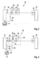
- Der Darstellung gemäß
Figur 2 ist zu entnehmen, dass aus einem Niederdruckkreis 72 Kraftstoff über eine Drosselstelle 76 der Zumesseinheit 48 zugeführt wird. Der Niederdruckkreis 72 steht über eine in der Darstellung gemäßFigur 2 nur schematisch angedeutete Leitung mit einem Sammelbehälter 74 in Verbindung. Über die Drosselstelle 76, die auch als Zuführdrossel bezeichnet wird, strömt der Kraftstoff der Zumesseinheit 48 zu, die in der Darstellung gemäßFigur 2 durch die rechteckige gestrichelte Umrahmung angedeutet ist. Das Gehäuse, in dem die Zumesseinheit 48 untergebracht ist, ist in derFigur 2 nicht näher dargestellt. - In Regenerationspausen, d.h. dann, wenn der Dieselpartikelfilter 44 nicht regeneriert werden soll, d.h. kein Abbrand von in diesem angelagerten Rußpartikeln durchgeführt wird, unterbricht das der Drosselstelle 76 nachgeschaltete Schließventil 54 den Zufluss von Kraftstoff zur Zumesseinheit 48. In diesem Falle strömt der Kraftstoff über ein zum Beispiel als Rückschlagventil ausgebildetes Überströmventil 80 über einen Rücklauf 82 zum Sammelbehälter 74 zurück. Darüber hinaus umfasst die Zumesseinheit 48 gemäß der Darstellung in
Figur 2 einen ersten Drucksensor 50, mit welchem die erforderliche, einzudosierende Dosiermenge berechnet wird. Diese wird über das Dosierventil 56 zur Verfügung gestellt und von diesem zum Einspritzventil 40 gefördert. Bei diesem handelt es sich bevorzugt um ein federbelastetes Einspritzventil, welches bei Überschreiten eines bestimmten Öffnungsdrucks öffnet, so dass Kraftstoff in die Abgasleitung 38 eingespritzt werden kann. - Die Zumesseinheit 48 umfasst darüber hinaus einen weiteren, dem Dosierventil 56 nachgeschalteten Drucksensor 52. Dieser stromab angeordnete zweite Drucksensor 52 dient zur Erkennung einer Leckage in der Leitung, die sich zum Einspritzventil 40 erstreckt, und misst den Druck des Kraftstoffs bei Austritt aus der Zumesseinheit 48.
-
Figur 3 zeigt die erfindungsgemäß vorgeschlagene Zumesseinheit 48. Analog zur Darstellung gemäßFigur 2 wird der Zumesseinheit 48 gemäß der Darstellung inFigur 3 Kraftstoff aus einem Niederdruckkreis 72 zugeführt. Dem Niederdruckkreis 72 wird der Kraftstoff aus einem Sammelbehälter 74 zugeführt. Bei geschlossenem Schließventil 54, d.h. in Regenerationspausen des Dieselpartikelfilters 44, zweigt vor einer Zulaufdrossel 76 der Rücklauf 82 zum Sammelbehälter 74 ab, in diesem Falle gelangt kein Kraftstoff aus dem Niederdruckkreis 72 über die Zulaufdrossel 76 zur Zumesseinheit 48. Der Darstellung gemäßFigur 3 ist zu entnehmen, dass die Zumesseinheit 48 einen Anschluss zwischen dem Schließventil 54 und dem Dosierventil 56 aufweist. An diesem Anschluss wird ein zweites Überströmventil 80 sowie ein Parallelrücklauf 88 zum Sammelbehälter 74 angeschlossen. Der Parallelrücklauf 88 ist zwischen dem Schließventil 54 und dem Dosierventil 56 und/oder einem Druckdämpfer 78 zur Aufnahme eines zusätzlichen Kraftstoffvolumens angeschlossen und steht mit dem Sammelbehälter 74 in Verbindung. Durch diese Lösung kann das mittlere Druckniveau, welches in der Zumesseinheit 48 herrscht, d.h. ein Betriebsdruckniveau in der Zumesseinheit 48, eingestellt und aufrechterhalten werden. Darüber hinaus kann der Druckverlauf durch entsprechende Dimensionierung der Zulaufdrossel 76 beeinflusst werden. - Wie aus der Darstellung gemäß
Figur 3 hervorgeht, befindet sich zwischen dem Schließventil 54 und dem Dosierventil 56 der Druckdämpfer 78, der als Erweiterung des Strömungsquerschnitts, als Dämpfungsvolumen oder dergleichen ausgestaltet sein kann. Wie aus der Darstellung gemäßFigur 3 weiter hervorgeht, ist die Zumesseinheit 48 so aufgebaut, dass der Anschluss des zweiten Parallelrücklaufes 88 zum Sammelbehälter 74 zwischen dem Schließventil 54 und dem Dosierventil 56 liegt. Dem Druckdämpfer 78 ist über eine Dämpferdrossel 84 der erste Drucksensor 50 zugeordnet. Der zweite Drucksensor 52 liegt am Ausgang der Zumesseinheit 48, dem Dosierventil 56 nachgeschaltet. Über den zweiten - Drucksensor 52 wird eine Leckage in der Leitung, die zum Einspritzventil 40 verläuft, erkannt. Über das Einspritzventil 40, welches im einfachsten Falle als ein Rückschlagventil ausgeführt sein kann, wird Kraftstoff in die Abgasleitung 38 und das dort strömende Abgas eingebracht. Das im einfachsten Falle als Rückschlagventil ausgebildete Einspritzventil 40 öffnet, sobald ein bestimmter Öffnungsdruck in der Zuleitung, d.h. nach der Zumesseinheit 48, erreicht ist. Dieser Öffnungsdruck wird über den zweiten Drucksensor 52, der in der Zumesseinheit 48 enthalten ist, kontinuierlich gemessen.
- Das zweite Überströmventil 80, welches in dem Parallelrücklauf 88 zum Sammelbehälter 74 enthalten ist, kann ein externes Bauteil sein, welches als separates Bauteil in dem Parallelrücklauf 88 bzw. am nicht dargestellten Gehäuse der Zumesseinheit 48 vorgesehen ist. Daneben kann das zweite Überströmventil 80 auch in die Zumesseinheit 48 integriert sein. Je nach Einsatzzweck und Fahrzeugapplikationen kann der Öffnungsdruck angepasst werden und der Durchfluss des Kraftstoffs durch das zweite Überströmventil 80 zum Sammelbehälter 54 beeinflusst werden.
- Darüber hinaus ist innerhalb der Zumesseinheit 48 ein möglichst großer Druckdämpfer 78 vorgesehen. Zwischen diesem und dem ersten Drucksensor 50 kann eine weitere Dämpferdrossel 84 vorgesehen sein. Durch geeignete Abstimmung des Drosselquerschnittes der Dämpferdrossel 84 in Verbindung mit dem definierten Öffnungszeitpunkt des zweiten Überströmventils 80, das im Parallelrücklauf 88 aufgenommen ist, kann in der Zumesseinheit 48 der gewünschte Betriebsdruckbereich eingestellt und auch für den Betrieb aufrechterhalten werden.
- Bei Bedarf können Dämpfungsmaßnahmen auch außerhalb der Zumesseinheit 48 vorgenommen werden. Zum Beispiel kann das Druckniveau reduziert werden, damit eventuellen Spezifikationen des Schließventils 54 Rechnung getragen werden kann. Optional können Druckschwingungen, die sich im Niederdruckkreis 72 einstellen, vor der Zumesseinheit 48 dadurch reduziert werden, dass ein Dämpfungsvolumen im Bereich der Zulaufdrossel 76 vor der Zumesseinheit 48 vorgesehen wird. Hierzu kann zum Beispiel ein elastischer Schlauch oder dergleichen eingesetzt werden, der sich zwischen dem Niederdruckkreis 72 und der Zumesseinheit 48 erstreckt.
- Die Anbindung des ersten Drucksensors 50 hinter dem Schließventil 54 erfolgt zum Beispiel über eine im Ventilgehäuse vorgesehene Bohrung. Durch die direkte Anbindung des ersten Drucksensors 50 können Druckschwankungen und Kavitationsereignisse, die sich stromab des Schließventils 54 einstellen und somit Versorgungsdruckschwankungen hervorrufen, ausgeglichen werden. Um Druckspitzen vor dem ersten Drucksensor 50 zu vermeiden oder zu minimieren, können folgende Maßnahmen getroffen werden: einfache Anbindung des ersten Drucksensors 50 an die Dämpferdrossel 84, wie in
Figur 3 dargestellt. Des Weiteren kann durch Darstellung eines großzügig ausgelegten Kraftstoffvolumens, d.h. des Druckdämpfers 78, mit Hilfe des bereits erwähnten Ausgleichsraumes oder des Erweiterungsteils eine Dämpfung von Druckschwankungen erreicht werden. - Die Dosierung der letztlich zur Einspritzung in die Abgasleitung 38 erforderlichen Kraftstoffmenge erfolgt mit Hilfe des Dosierventils 56, dem zur Messung des Druckniveaus der zweite Drucksensor 52 nachgeschaltet ist.
- Das Schließventil 54 unterbricht in den Regenerationspausen den Zufluss von Kraftstoff zum Dosierventil 56. In diesem Falle strömt der Kraftstoff über das erste Überströmventil 80, welches der Zulaufdrossel 76 vorgeschaltet ist, und den Rücklauf 82 in den Sammelbehälter 74 zurück. Wird das Schließventil 54 geöffnet, kann der Kraftstoff nach Passage des Druckdämpfers 78 zum Dosierventil 56 gelangen. An einer Verbindungsbohrung zwischen dem Schließventil 54 und dem Dosierventil 56 ist zur optimalen Abstimmung bzw. Berechnung der in den Abgasstrom einzudosierenden Kraftstoffmenge der erste Drucksensor 50 angeordnet. Dieser dient der Berechnung der erforderlichen Dosiermenge. Diese Dosiermenge wird über das Dosierventil 56 zur Verfügung gestellt und zum Einspritzventil 40 gefördert. Bei dem Einspritzventil 40 kann es sich - wie oben erwähnt - um ein passiv öffnendes Ventil handeln, so zum Beispiel ein Rückschlagventil, das sich bei Erreichen eines bestimmten Öffnungsdruckes öffnet und Kraftstoff, insbesondere Dieselkraftstoff, in die Abgasleitung 38 des Abgastraktes 36 einspritzt.
- Bei Einsatz des erfindungsgemäß vorgeschlagenen Abgasbehandlungssystems wird das Einspritzventil 40 zum Beispiel in einen in der Darstellung gemäß
Figur 3 nicht dargestellten Kühlkörper eingeschraubt, der zum Beispiel direkt über den Kühlwasserkreislauf der Verbrennungskraftmaschine 10 versorgt wird. Die Kühlung des Einspritzventils 40 kann auch mit Hilfe eines in der Zeichnung nicht dargestellten, am Einspritzventil 40 vorbeigeführten Kraftstoffstromes ermöglicht werden. - Die prinzipielle Anbindung des zweiten Drucksensors 52 ist in den Ausführungsformen gemäß der Darstellungen in den
Figuren 2 und 3 identisch. - Gemäß der Darstellung in
Figur 3 wird stromab des Schließventils 54 bzw. stromab des ersten Drucksensors 50 in der Zumesseinheit 48 ein zusätzliches als Druckdämpfer dienendes Volumen 78 zur Verfügung gestellt. Dieses kann zum Beispiel als Querschnittserweiterung in der Leitung der Zumesseinheit 48 vorgesehen sein, so zum Beispiel durch eine Bohrungserweiterung dargestellt werden. Das Zurverfügungstellen dieses zusätzlichen Volumens 78 > 2 cm3 oder zwischen 2 cm3 und 20 cm3, insbesondere zwischen 2 cm3 und 10 cm3, dient als Dämpfungsvolumen innerhalb der Zumesseinheit 48. - Die Zumesseinheit 48 ist, wie bereits erwähnt, gemäß der Darstellung in
Figur 3 , an den Niederdruckkreis 72 angeschlossen. Die Dosierleitung verlässt die Zumesseinheit 48 stromab des zweiten Drucksensors 52 und erstreckt sich bis zum Einspritzventil 40. Mit Hilfe von vorbeiströmendem Kraftstoff kann dieses auf kostengünstige Weise gekühlt werden, da die Abgastemperatur beim Durchströmen des Oxidationskatalysators auf ca. 600 °C ansteigt. Ferner kann mit Hilfe einer in der Darstellung gemäßFigur 3 nicht dargestellten Kühleinrichtung ein schnelles Altern des Kraftstoffs vermieden werden. Kurz vor der Auslassöffnung des Einspritzventils 40 kann an die Dosierleitung ein Kraftstoffrücklauf angeschlossen werden, der über ein steuer- bzw. regelbares Druckventil wiederum an den Sammelbehälter 74 angeschlossen ist.
Claims (14)
- Eindosierungsvorrichtung für Kraftstoff vor einem Oxidationskatalysator (42) im Abgastrakt (36) einer Verbrennungskraftmaschine (10), wobei nach einer Versorgungseinrichtung (72) für Kraftstoff ein Ventil (54) sowie eine Einspritzdüse (40) in eine Leitung einer Zumesseinheit (48) integriert sind, von der ein Rücklauf (82) mit einem ersten Überströmventil (80) abzweigt, dadurch gekennzeichnet, dass stromabwärts des Ventils (54) ein weiterer Rücklauf (88) mit einem ein mittleres Druckniveau der Zumesseinheit (48) beeinflussenden Ventil (90) angeordnet ist.
- Eindosierungsvorrichtung nach Anspruch 1, dadurch gekennzeichnet, dass stromabwärts des Ventils (54) ein Dosierventil (56) angeordnet ist.
- Eindosierungsvorrichtung nach Anspruch 2, dadurch gekennzeichnet, dass der weitere Rücklauf (88) zwischen dem Ventil (54) und dem Dosierventil (56) angeordnet ist.
- Eindosierungsvorrichtung nach einem der vorhergehenden Ansprüche, dadurch gekennzeichnet, dass der Versorgungsvorrichtung (72) für Kraftstoff, insbesondere für Dieselkraftstoff, nachgeschaltet, eine Drosselstelle (76, 86) der Zumesseinheit (48) vorgeschaltet ist.
- Eindosierungsvorrichtung nach einem der vorhergehenden Ansprüche, dadurch gekennzeichnet, dass eine Einrichtung (78, 84) zur Dämpfung von Druckschwankungen in das Leitungssystem der Zumesseinheit (48) integriert ist.
- Eindosierungsvorrichtung nach Anspruch 5, dadurch gekennzeichnet, dass die Zumesseinheit (48) über den ein erstes Überströmventil (80) aufweisenden Rücklauf (82) an einen Sammelbehälter (74) im Kraftfahrzeug angeschlossen ist und stromabwärts nach der Anschlussstelle des Rücklaufs (82) die Zumesseinheit (48) und/oder das Schließventil (54) mit der Einrichtung (78, 84) zur Dämpfung von Druckschwankungen versehen ist.
- Eindosierungsvorrichtung nach Anspruch 5, dadurch gekennzeichnet, dass die Einrichtung zur Dämpfung (78, 84) von Druckschwankungen zumindest eine Dämpferdrossel (84) und/oder eine der Zumesseinheit (48) zugeordnete Kammer oder eine Erweiterung im Leitungssystem der Zumesseinheit (48) umfasst.
- Eindosierungsvorrichtung nach Anspruch 2, 4 und 7, dadurch gekennzeichnet, dass die Zulaufdrossel (86) stromabwärts nach der Anschlussstelle des Rücklaufes (82) vor dem Schließventil (54) und die Dämpferdrossel (84) in der Zumesseinheit (48) zwischen dem Schließventil (54) und dem Dosierventil (56) vorgesehen ist.
- Ein dosierungsvorrichtung nach Anspruch 2 und 5, dadurch gekennzeichnet, dass die Einrichtung (78, 84) zur Dämpfung von Druckschwankungen zwischen dem Schließventil (54) und dem Dosierventil (56) in die Zumesseinheit (48) integriert ist.
- Eindosierungsvorrichtung nach Anspruch 7, dadurch gekennzeichnet, dass die Einrichtung (78, 84) zur Dämpfung von Druckschwankungen als Behälter oder als Erweiterungsteil zur Aufnahme eines zusätzlichen Kraftstoffvolumens Teil eines Ventilblockes oder Teil des Leitungssystems der Zumesseinheit (48) ist.
- Eindosierungsvorrichtung nach Anspruch 2 und 5, dadurch gekennzeichnet, dass in der Zumesseinheit (48) nach dem Schließventil (54) und vor dem Dosierventil (56) zumindest ein erster Drucksensor (50) vorgesehen ist, der mit der Einrichtung (78, 84) zur Dämpfung von Druckschwankungen in Wirkverbindung steht.
- Eindosierungsvorrichtung nach einem der vorhergehenden Ansprüche, dadurch gekennzeichnet, dass zwischen dem Schließventil (54) und dem Dosierventil (56) zumindest eine Drosselstelle (84) mit dem ersten Drucksensor (50) verbunden ist, die mit der Einrichtung (78) zur Dämpfung von Druckschwankungen in Wirkverbindung steht.
- Eindosierungsvorrichtung nach einem der vorhergehenden Ansprüche, dadurch gekennzeichnet, dass zwischen dem Schließventil (54) und dem Dosierventil (56) oder einem Druckdämpfer (78) der Parallelrücklauf (88) mit einem zweiten Überstromventil (90) verläuft.
- Eindosierungsvorrichtung nach einem der vorhergehenden Ansprüche, dadurch gekennzeichnet, dass die Einspritzdüse (40) als Einspritzventil ausgebildet ist.
Applications Claiming Priority (2)
| Application Number | Priority Date | Filing Date | Title |
|---|---|---|---|
| DE102008040463A DE102008040463A1 (de) | 2008-07-16 | 2008-07-16 | Vorrichtung zur Eindosierung von Kraftstoff |
| PCT/EP2009/055972 WO2010006829A1 (de) | 2008-07-16 | 2009-05-18 | Vorrichtung zur eindosierung von kraftstoff |
Publications (2)
| Publication Number | Publication Date |
|---|---|
| EP2304200A1 EP2304200A1 (de) | 2011-04-06 |
| EP2304200B1 true EP2304200B1 (de) | 2013-09-25 |
Family
ID=41008904
Family Applications (1)
| Application Number | Title | Priority Date | Filing Date |
|---|---|---|---|
| EP09779499.4A Active EP2304200B1 (de) | 2008-07-16 | 2009-05-18 | Vorrichtung zur eindosierung von kraftstoff |
Country Status (7)
| Country | Link |
|---|---|
| US (1) | US8528324B2 (de) |
| EP (1) | EP2304200B1 (de) |
| JP (1) | JP5312583B2 (de) |
| CN (1) | CN102099554A (de) |
| DE (1) | DE102008040463A1 (de) |
| RU (1) | RU2490483C2 (de) |
| WO (1) | WO2010006829A1 (de) |
Families Citing this family (11)
| Publication number | Priority date | Publication date | Assignee | Title |
|---|---|---|---|---|
| FR2839446B1 (fr) | 2002-05-13 | 2006-06-30 | Oreal | Composes diazirine-actifs photo-activables, compositions les contenant et leurs utilisations |
| DE102011081580A1 (de) * | 2011-03-04 | 2012-09-06 | Robert Bosch Gmbh | Abgasnachbehandlungssystem einer Brennkraftmaschine und Verfahren zur Eindosierung einer Flüssigkeit in den Abgaskanal der Brennkraftmaschine |
| FR2973832B1 (fr) * | 2011-04-08 | 2015-05-29 | Peugeot Citroen Automobiles Sa | Dispositif de dosage d'injection dans un systeme de reduction catalytique selective |
| DE102011081628A1 (de) * | 2011-08-26 | 2013-02-28 | Robert Bosch Gmbh | Dosiersystem für ein flüssiges Reduktionsmittel |
| DE102012222040A1 (de) | 2012-12-03 | 2014-06-05 | Robert Bosch Gmbh | Eindosierungsvorrichtung |
| DE102013220799B4 (de) * | 2013-10-15 | 2018-11-29 | Continental Automotive Gmbh | Dosieranlage zur Zuführung von Substanzen in Gasströme |
| JP2016176365A (ja) * | 2015-03-19 | 2016-10-06 | いすゞ自動車株式会社 | 内燃機関及び捕集装置の強制再生方法 |
| JP6489642B2 (ja) * | 2015-04-27 | 2019-03-27 | 日野自動車株式会社 | 排気浄化装置 |
| CN106593604B (zh) * | 2016-12-26 | 2022-05-24 | 南岳电控(衡阳)工业技术股份有限公司 | 一种柴油车hc喷射装置 |
| CN107060954B (zh) * | 2017-03-22 | 2023-04-07 | 中国第一汽车股份有限公司 | 用于净化排气碳烟颗粒的喷射系统及控制方法 |
| WO2020214920A1 (en) | 2019-04-18 | 2020-10-22 | Cummins Inc. | Apparatus, system, and method for thermal management by deploying engine fueling on demand |
Family Cites Families (16)
| Publication number | Priority date | Publication date | Assignee | Title |
|---|---|---|---|---|
| JPH0631153Y2 (ja) * | 1987-05-26 | 1994-08-22 | ダイハツ工業株式会社 | 内燃機関の吸気圧検出装置 |
| DE19946900A1 (de) * | 1999-06-22 | 2000-12-28 | Bosch Gmbh Robert | Vorrichtung zur Dosierung eines Reduktionsmittels |
| JP4306101B2 (ja) * | 2000-07-24 | 2009-07-29 | トヨタ自動車株式会社 | エンジンの燃料供給装置 |
| JP2002242780A (ja) * | 2001-02-16 | 2002-08-28 | Toyota Motor Corp | 内燃機関の燃料供給装置 |
| JP2003344713A (ja) | 2002-05-29 | 2003-12-03 | Kyocera Corp | 光素子モジュール及びその製造方法 |
| DE10324482B4 (de) * | 2003-05-30 | 2014-08-21 | Robert Bosch Gmbh | Vorrichtung zur Dosierung eines Reduktionsmittels zum Abgas eines Verbrennungsmotors |
| US7594393B2 (en) | 2004-09-07 | 2009-09-29 | Robert Bosch Gmbh | Apparatus for introducing a reducing agent into the exhaust of an internal combustion engine |
| AT500849B8 (de) * | 2004-11-15 | 2007-02-15 | Pankl Emission Control Systems | Harnstoffdosiervorrichtung |
| DE102005034704A1 (de) | 2005-07-26 | 2007-02-01 | Robert Bosch Gmbh | Vorrichtung und Verfahren zur Regeneration eines Partikelfilters |
| DE102005046070A1 (de) * | 2005-09-27 | 2007-03-29 | Daimlerchrysler Ag | Vorrichtung zum Dosieren von Kraftstoff in ein Abgassystem einer Brennkraftmaschine |
| DE102006009099A1 (de) * | 2006-02-28 | 2007-08-30 | Daimlerchrysler Ag | Einspritzsystem mit einer Vorrichtung zum Dosieren von Kraftstoff in ein Abgassystem einer Brennkraftmaschine und einem Verfahren hierzu |
| DE102006032155A1 (de) | 2006-07-12 | 2008-01-24 | Daimler Ag | Brennkraftmaschine eines Kraftfahrzeugs |
| EP2047076A1 (de) | 2006-07-13 | 2009-04-15 | Inergy Automotive Systems Research (Société A.) | System und verfahren zur speicherung eines zusatzes und dessen injizierung in abgase eines motors |
| JP4616817B2 (ja) * | 2006-11-10 | 2011-01-19 | 三菱重工業株式会社 | エンジンの蓄圧式燃料噴射装置 |
| DE102006062491A1 (de) * | 2006-12-28 | 2008-07-03 | Robert Bosch Gmbh | Vorrichtung zur Dosierung von Kraftstoff zum Abgassystem eines Verbrennungsmotors |
| US8116972B2 (en) * | 2008-02-08 | 2012-02-14 | Ford Global Technologies, Llc | System and method for determining a vehicle refueling strategy |
-
2008
- 2008-07-16 DE DE102008040463A patent/DE102008040463A1/de not_active Withdrawn
-
2009
- 2009-05-18 US US13/054,320 patent/US8528324B2/en not_active Expired - Fee Related
- 2009-05-18 RU RU2011105053/06A patent/RU2490483C2/ru not_active IP Right Cessation
- 2009-05-18 JP JP2011517827A patent/JP5312583B2/ja not_active Expired - Fee Related
- 2009-05-18 WO PCT/EP2009/055972 patent/WO2010006829A1/de not_active Ceased
- 2009-05-18 EP EP09779499.4A patent/EP2304200B1/de active Active
- 2009-05-18 CN CN2009801279419A patent/CN102099554A/zh active Pending
Also Published As
| Publication number | Publication date |
|---|---|
| RU2490483C2 (ru) | 2013-08-20 |
| RU2011105053A (ru) | 2012-08-27 |
| WO2010006829A1 (de) | 2010-01-21 |
| JP5312583B2 (ja) | 2013-10-09 |
| EP2304200A1 (de) | 2011-04-06 |
| JP2011528080A (ja) | 2011-11-10 |
| US20110138792A1 (en) | 2011-06-16 |
| CN102099554A (zh) | 2011-06-15 |
| DE102008040463A1 (de) | 2010-01-21 |
| US8528324B2 (en) | 2013-09-10 |
Similar Documents
| Publication | Publication Date | Title |
|---|---|---|
| EP2304200B1 (de) | Vorrichtung zur eindosierung von kraftstoff | |
| EP1989410B1 (de) | Einspritzsystem mit einer vorrichtung zum dosieren von kraftstoff in ein abgassystem einer brennkraftmaschine und einem verfahren hierzu | |
| DE102009026754B4 (de) | Abgasreinigungsvorrichtung und Verfahren zum Reinigen von Abgas | |
| DE19947198B4 (de) | Vorrichtung zum Nachbehandeln von Abgasen einer Brennkraftmaschine | |
| EP2789839A2 (de) | System und Verfahren zur Wassereinspritzung für eine Brennkraftmaschine | |
| DE4041628A1 (de) | Gemischverdichtende brennkraftmaschine mit sekundaerlufteinblasung und mit luftmassenmessung im saugrohr | |
| DE102012113108A1 (de) | Fahrzeug mit einem system und einem verfahren zum diagnostizieren von sekundärlufteinblas-vorrichtung | |
| EP2647814B1 (de) | Verfahren und Vorrichtung zum Steuern des Motorbremsbetriebs an Brennkraftmaschinen | |
| EP3346120B1 (de) | Wassereinspritzvorrichtung einer brennkraftmaschine und verfahren zum betreiben einer solchen wassereinspritzvorrichtung | |
| DE102011003912A1 (de) | Vorrichtung und Verfahren zur Eindosierung einer Flüssigkeit in den Abgasstrang einer Brennkraftmaschine | |
| WO2009024447A1 (de) | Einspritzanlage für eine brennkraftmaschine | |
| EP1582709B1 (de) | Regenerationsverfahren für ein Partikelfilter sowie Abgasanlage mit Partikelfilter | |
| WO2010052120A1 (de) | Einspritzanlage für eine brennkraftmaschine | |
| EP2337933A1 (de) | Vorrichtung zur eindosierung von kraftstoff | |
| DE102005061876A1 (de) | Verfahren und Vorrichtung zur Steuerung eines Abgasnachbehandlungssystems | |
| WO2009010569A1 (de) | Vorrichtung und verfahren zur dosierung eines reduktionsmittels in einen abgastrakt eines fahrzeugs | |
| WO2010072443A1 (de) | Vorrichtung zur eindosierung von kraftstoff | |
| DE102010035364B4 (de) | Vorrichtung zum Betreiben einer Brennkraftmaschine | |
| DE102017205777A1 (de) | Verfahren zur Überwachung des Volumenstroms eines Dosierventils eines fluidischen Dosiersystems einer Brennkraftmaschine insbesondere eines Kraftfahrzeugs | |
| WO2011113659A1 (de) | Verfahren und vorrichtung zur bewertung eines einspritzorgans | |
| DE102013108225A1 (de) | Abgasrückführungs-Steuervorrichtung und Verfahren für eine Brennkraftmaschine | |
| DE10233945A1 (de) | Verfahren zur Reinigung eines Partikelfilters | |
| DE102018216767A1 (de) | Maschinensystem und verfahren zum steuern von diesem | |
| EP3337962B1 (de) | Kraftstoffversorgungseinrichtung zur motoreinspritzung und zur abgasnachbehandlung | |
| DE102013224414A1 (de) | Verfahren zum Betreiben eines Fluidfördersystems |
Legal Events
| Date | Code | Title | Description |
|---|---|---|---|
| PUAI | Public reference made under article 153(3) epc to a published international application that has entered the european phase |
Free format text: ORIGINAL CODE: 0009012 |
|
| 17P | Request for examination filed |
Effective date: 20110216 |
|
| AK | Designated contracting states |
Kind code of ref document: A1 Designated state(s): AT BE BG CH CY CZ DE DK EE ES FI FR GB GR HR HU IE IS IT LI LT LU LV MC MK MT NL NO PL PT RO SE SI SK TR |
|
| AX | Request for extension of the european patent |
Extension state: AL BA RS |
|
| DAX | Request for extension of the european patent (deleted) | ||
| GRAP | Despatch of communication of intention to grant a patent |
Free format text: ORIGINAL CODE: EPIDOSNIGR1 |
|
| INTG | Intention to grant announced |
Effective date: 20130625 |
|
| GRAS | Grant fee paid |
Free format text: ORIGINAL CODE: EPIDOSNIGR3 |
|
| GRAA | (expected) grant |
Free format text: ORIGINAL CODE: 0009210 |
|
| AK | Designated contracting states |
Kind code of ref document: B1 Designated state(s): AT BE BG CH CY CZ DE DK EE ES FI FR GB GR HR HU IE IS IT LI LT LU LV MC MK MT NL NO PL PT RO SE SI SK TR |
|
| REG | Reference to a national code |
Ref country code: GB Ref legal event code: FG4D Free format text: NOT ENGLISH |
|
| REG | Reference to a national code |
Ref country code: CH Ref legal event code: EP |
|
| REG | Reference to a national code |
Ref country code: AT Ref legal event code: REF Ref document number: 633802 Country of ref document: AT Kind code of ref document: T Effective date: 20131015 |
|
| REG | Reference to a national code |
Ref country code: IE Ref legal event code: FG4D Free format text: LANGUAGE OF EP DOCUMENT: GERMAN |
|
| REG | Reference to a national code |
Ref country code: DE Ref legal event code: R096 Ref document number: 502009008071 Country of ref document: DE Effective date: 20131121 |
|
| PG25 | Lapsed in a contracting state [announced via postgrant information from national office to epo] |
Ref country code: LT Free format text: LAPSE BECAUSE OF FAILURE TO SUBMIT A TRANSLATION OF THE DESCRIPTION OR TO PAY THE FEE WITHIN THE PRESCRIBED TIME-LIMIT Effective date: 20130925 Ref country code: HR Free format text: LAPSE BECAUSE OF FAILURE TO SUBMIT A TRANSLATION OF THE DESCRIPTION OR TO PAY THE FEE WITHIN THE PRESCRIBED TIME-LIMIT Effective date: 20130925 Ref country code: NO Free format text: LAPSE BECAUSE OF FAILURE TO SUBMIT A TRANSLATION OF THE DESCRIPTION OR TO PAY THE FEE WITHIN THE PRESCRIBED TIME-LIMIT Effective date: 20131225 Ref country code: SE Free format text: LAPSE BECAUSE OF FAILURE TO SUBMIT A TRANSLATION OF THE DESCRIPTION OR TO PAY THE FEE WITHIN THE PRESCRIBED TIME-LIMIT Effective date: 20130925 |
|
| REG | Reference to a national code |
Ref country code: NL Ref legal event code: VDEP Effective date: 20130925 |
|
| REG | Reference to a national code |
Ref country code: LT Ref legal event code: MG4D |
|
| PG25 | Lapsed in a contracting state [announced via postgrant information from national office to epo] |
Ref country code: GR Free format text: LAPSE BECAUSE OF FAILURE TO SUBMIT A TRANSLATION OF THE DESCRIPTION OR TO PAY THE FEE WITHIN THE PRESCRIBED TIME-LIMIT Effective date: 20131226 Ref country code: LV Free format text: LAPSE BECAUSE OF FAILURE TO SUBMIT A TRANSLATION OF THE DESCRIPTION OR TO PAY THE FEE WITHIN THE PRESCRIBED TIME-LIMIT Effective date: 20130925 Ref country code: FI Free format text: LAPSE BECAUSE OF FAILURE TO SUBMIT A TRANSLATION OF THE DESCRIPTION OR TO PAY THE FEE WITHIN THE PRESCRIBED TIME-LIMIT Effective date: 20130925 Ref country code: SI Free format text: LAPSE BECAUSE OF FAILURE TO SUBMIT A TRANSLATION OF THE DESCRIPTION OR TO PAY THE FEE WITHIN THE PRESCRIBED TIME-LIMIT Effective date: 20130925 |
|
| PG25 | Lapsed in a contracting state [announced via postgrant information from national office to epo] |
Ref country code: IS Free format text: LAPSE BECAUSE OF FAILURE TO SUBMIT A TRANSLATION OF THE DESCRIPTION OR TO PAY THE FEE WITHIN THE PRESCRIBED TIME-LIMIT Effective date: 20140125 Ref country code: SK Free format text: LAPSE BECAUSE OF FAILURE TO SUBMIT A TRANSLATION OF THE DESCRIPTION OR TO PAY THE FEE WITHIN THE PRESCRIBED TIME-LIMIT Effective date: 20130925 Ref country code: RO Free format text: LAPSE BECAUSE OF FAILURE TO SUBMIT A TRANSLATION OF THE DESCRIPTION OR TO PAY THE FEE WITHIN THE PRESCRIBED TIME-LIMIT Effective date: 20130925 Ref country code: CZ Free format text: LAPSE BECAUSE OF FAILURE TO SUBMIT A TRANSLATION OF THE DESCRIPTION OR TO PAY THE FEE WITHIN THE PRESCRIBED TIME-LIMIT Effective date: 20130925 Ref country code: EE Free format text: LAPSE BECAUSE OF FAILURE TO SUBMIT A TRANSLATION OF THE DESCRIPTION OR TO PAY THE FEE WITHIN THE PRESCRIBED TIME-LIMIT Effective date: 20130925 Ref country code: NL Free format text: LAPSE BECAUSE OF FAILURE TO SUBMIT A TRANSLATION OF THE DESCRIPTION OR TO PAY THE FEE WITHIN THE PRESCRIBED TIME-LIMIT Effective date: 20130925 |
|
| PG25 | Lapsed in a contracting state [announced via postgrant information from national office to epo] |
Ref country code: CY Free format text: LAPSE BECAUSE OF FAILURE TO SUBMIT A TRANSLATION OF THE DESCRIPTION OR TO PAY THE FEE WITHIN THE PRESCRIBED TIME-LIMIT Effective date: 20130925 Ref country code: PL Free format text: LAPSE BECAUSE OF FAILURE TO SUBMIT A TRANSLATION OF THE DESCRIPTION OR TO PAY THE FEE WITHIN THE PRESCRIBED TIME-LIMIT Effective date: 20130925 Ref country code: ES Free format text: LAPSE BECAUSE OF FAILURE TO SUBMIT A TRANSLATION OF THE DESCRIPTION OR TO PAY THE FEE WITHIN THE PRESCRIBED TIME-LIMIT Effective date: 20130925 |
|
| REG | Reference to a national code |
Ref country code: DE Ref legal event code: R097 Ref document number: 502009008071 Country of ref document: DE |
|
| PG25 | Lapsed in a contracting state [announced via postgrant information from national office to epo] |
Ref country code: PT Free format text: LAPSE BECAUSE OF FAILURE TO SUBMIT A TRANSLATION OF THE DESCRIPTION OR TO PAY THE FEE WITHIN THE PRESCRIBED TIME-LIMIT Effective date: 20140127 |
|
| PLBE | No opposition filed within time limit |
Free format text: ORIGINAL CODE: 0009261 |
|
| STAA | Information on the status of an ep patent application or granted ep patent |
Free format text: STATUS: NO OPPOSITION FILED WITHIN TIME LIMIT |
|
| PG25 | Lapsed in a contracting state [announced via postgrant information from national office to epo] |
Ref country code: IT Free format text: LAPSE BECAUSE OF FAILURE TO SUBMIT A TRANSLATION OF THE DESCRIPTION OR TO PAY THE FEE WITHIN THE PRESCRIBED TIME-LIMIT Effective date: 20130925 |
|
| 26N | No opposition filed |
Effective date: 20140626 |
|
| PG25 | Lapsed in a contracting state [announced via postgrant information from national office to epo] |
Ref country code: DK Free format text: LAPSE BECAUSE OF FAILURE TO SUBMIT A TRANSLATION OF THE DESCRIPTION OR TO PAY THE FEE WITHIN THE PRESCRIBED TIME-LIMIT Effective date: 20130925 |
|
| REG | Reference to a national code |
Ref country code: DE Ref legal event code: R097 Ref document number: 502009008071 Country of ref document: DE Effective date: 20140626 |
|
| PG25 | Lapsed in a contracting state [announced via postgrant information from national office to epo] |
Ref country code: LU Free format text: LAPSE BECAUSE OF FAILURE TO SUBMIT A TRANSLATION OF THE DESCRIPTION OR TO PAY THE FEE WITHIN THE PRESCRIBED TIME-LIMIT Effective date: 20140518 |
|
| REG | Reference to a national code |
Ref country code: CH Ref legal event code: PL |
|
| GBPC | Gb: european patent ceased through non-payment of renewal fee |
Effective date: 20140518 |
|
| PG25 | Lapsed in a contracting state [announced via postgrant information from national office to epo] |
Ref country code: MC Free format text: LAPSE BECAUSE OF FAILURE TO SUBMIT A TRANSLATION OF THE DESCRIPTION OR TO PAY THE FEE WITHIN THE PRESCRIBED TIME-LIMIT Effective date: 20130925 Ref country code: CH Free format text: LAPSE BECAUSE OF NON-PAYMENT OF DUE FEES Effective date: 20140531 Ref country code: LI Free format text: LAPSE BECAUSE OF NON-PAYMENT OF DUE FEES Effective date: 20140531 |
|
| REG | Reference to a national code |
Ref country code: IE Ref legal event code: MM4A |
|
| PG25 | Lapsed in a contracting state [announced via postgrant information from national office to epo] |
Ref country code: IE Free format text: LAPSE BECAUSE OF NON-PAYMENT OF DUE FEES Effective date: 20140518 |
|
| PG25 | Lapsed in a contracting state [announced via postgrant information from national office to epo] |
Ref country code: GB Free format text: LAPSE BECAUSE OF NON-PAYMENT OF DUE FEES Effective date: 20140518 |
|
| REG | Reference to a national code |
Ref country code: AT Ref legal event code: MM01 Ref document number: 633802 Country of ref document: AT Kind code of ref document: T Effective date: 20140518 |
|
| PG25 | Lapsed in a contracting state [announced via postgrant information from national office to epo] |
Ref country code: AT Free format text: LAPSE BECAUSE OF NON-PAYMENT OF DUE FEES Effective date: 20140518 |
|
| PG25 | Lapsed in a contracting state [announced via postgrant information from national office to epo] |
Ref country code: MT Free format text: LAPSE BECAUSE OF FAILURE TO SUBMIT A TRANSLATION OF THE DESCRIPTION OR TO PAY THE FEE WITHIN THE PRESCRIBED TIME-LIMIT Effective date: 20130925 |
|
| REG | Reference to a national code |
Ref country code: FR Ref legal event code: PLFP Year of fee payment: 8 |
|
| PG25 | Lapsed in a contracting state [announced via postgrant information from national office to epo] |
Ref country code: BG Free format text: LAPSE BECAUSE OF FAILURE TO SUBMIT A TRANSLATION OF THE DESCRIPTION OR TO PAY THE FEE WITHIN THE PRESCRIBED TIME-LIMIT Effective date: 20130925 |
|
| PG25 | Lapsed in a contracting state [announced via postgrant information from national office to epo] |
Ref country code: TR Free format text: LAPSE BECAUSE OF FAILURE TO SUBMIT A TRANSLATION OF THE DESCRIPTION OR TO PAY THE FEE WITHIN THE PRESCRIBED TIME-LIMIT Effective date: 20130925 Ref country code: HU Free format text: LAPSE BECAUSE OF FAILURE TO SUBMIT A TRANSLATION OF THE DESCRIPTION OR TO PAY THE FEE WITHIN THE PRESCRIBED TIME-LIMIT; INVALID AB INITIO Effective date: 20090518 Ref country code: BE Free format text: LAPSE BECAUSE OF FAILURE TO SUBMIT A TRANSLATION OF THE DESCRIPTION OR TO PAY THE FEE WITHIN THE PRESCRIBED TIME-LIMIT Effective date: 20140531 |
|
| REG | Reference to a national code |
Ref country code: FR Ref legal event code: PLFP Year of fee payment: 9 |
|
| REG | Reference to a national code |
Ref country code: FR Ref legal event code: PLFP Year of fee payment: 10 |
|
| PG25 | Lapsed in a contracting state [announced via postgrant information from national office to epo] |
Ref country code: MK Free format text: LAPSE BECAUSE OF FAILURE TO SUBMIT A TRANSLATION OF THE DESCRIPTION OR TO PAY THE FEE WITHIN THE PRESCRIBED TIME-LIMIT Effective date: 20130925 |
|
| PGFP | Annual fee paid to national office [announced via postgrant information from national office to epo] |
Ref country code: FR Payment date: 20190521 Year of fee payment: 11 |
|
| PG25 | Lapsed in a contracting state [announced via postgrant information from national office to epo] |
Ref country code: FR Free format text: LAPSE BECAUSE OF NON-PAYMENT OF DUE FEES Effective date: 20200531 |
|
| PGFP | Annual fee paid to national office [announced via postgrant information from national office to epo] |
Ref country code: DE Payment date: 20250716 Year of fee payment: 17 |