EP2305923A2 - Tour d'éolienne et système et procédé de fabrication associés - Google Patents
Tour d'éolienne et système et procédé de fabrication associés Download PDFInfo
- Publication number
- EP2305923A2 EP2305923A2 EP10173655A EP10173655A EP2305923A2 EP 2305923 A2 EP2305923 A2 EP 2305923A2 EP 10173655 A EP10173655 A EP 10173655A EP 10173655 A EP10173655 A EP 10173655A EP 2305923 A2 EP2305923 A2 EP 2305923A2
- Authority
- EP
- European Patent Office
- Prior art keywords
- flange
- concrete segment
- formwork
- tension
- wind turbine
- Prior art date
- Legal status (The legal status is an assumption and is not a legal conclusion. Google has not performed a legal analysis and makes no representation as to the accuracy of the status listed.)
- Withdrawn
Links
- 238000000034 method Methods 0.000 title description 35
- 239000004567 concrete Substances 0.000 claims abstract description 111
- 238000009415 formwork Methods 0.000 claims description 102
- 229920002430 Fibre-reinforced plastic Polymers 0.000 claims description 78
- 239000011151 fibre-reinforced plastic Substances 0.000 claims description 78
- 239000011374 ultra-high-performance concrete Substances 0.000 claims description 32
- 239000000463 material Substances 0.000 claims description 29
- 239000000203 mixture Substances 0.000 claims description 4
- 230000013011 mating Effects 0.000 description 29
- 238000004519 manufacturing process Methods 0.000 description 10
- 230000006870 function Effects 0.000 description 5
- 239000004918 carbon fiber reinforced polymer Substances 0.000 description 4
- 230000006835 compression Effects 0.000 description 3
- 238000007906 compression Methods 0.000 description 3
- 230000002787 reinforcement Effects 0.000 description 3
- 229910000831 Steel Inorganic materials 0.000 description 2
- 239000000853 adhesive Substances 0.000 description 2
- 230000001070 adhesive effect Effects 0.000 description 2
- 238000005260 corrosion Methods 0.000 description 2
- 230000007797 corrosion Effects 0.000 description 2
- 238000005336 cracking Methods 0.000 description 2
- 230000003247 decreasing effect Effects 0.000 description 2
- 238000002347 injection Methods 0.000 description 2
- 239000007924 injection Substances 0.000 description 2
- 238000003780 insertion Methods 0.000 description 2
- 230000037431 insertion Effects 0.000 description 2
- 238000009987 spinning Methods 0.000 description 2
- 239000010959 steel Substances 0.000 description 2
- 230000004888 barrier function Effects 0.000 description 1
- 230000015572 biosynthetic process Effects 0.000 description 1
- 230000007613 environmental effect Effects 0.000 description 1
- 230000009972 noncorrosive effect Effects 0.000 description 1
- 238000005728 strengthening Methods 0.000 description 1
Images



Classifications
-
- E—FIXED CONSTRUCTIONS
- E04—BUILDING
- E04C—STRUCTURAL ELEMENTS; BUILDING MATERIALS
- E04C5/00—Reinforcing elements, e.g. for concrete; Auxiliary elements therefor
- E04C5/08—Members specially adapted to be used in prestressed constructions
- E04C5/085—Tensile members made of fiber reinforced plastics
-
- E—FIXED CONSTRUCTIONS
- E04—BUILDING
- E04C—STRUCTURAL ELEMENTS; BUILDING MATERIALS
- E04C5/00—Reinforcing elements, e.g. for concrete; Auxiliary elements therefor
- E04C5/07—Reinforcing elements of material other than metal, e.g. of glass, of plastics, or not exclusively made of metal
-
- E—FIXED CONSTRUCTIONS
- E04—BUILDING
- E04H—BUILDINGS OR LIKE STRUCTURES FOR PARTICULAR PURPOSES; SWIMMING OR SPLASH BATHS OR POOLS; MASTS; FENCING; TENTS OR CANOPIES, IN GENERAL
- E04H12/00—Towers; Masts or poles; Chimney stacks; Water-towers; Methods of erecting such structures
- E04H12/02—Structures made of specified materials
- E04H12/12—Structures made of specified materials of concrete or other stone-like material, with or without internal or external reinforcements, e.g. with metal coverings, with permanent form elements
-
- E—FIXED CONSTRUCTIONS
- E04—BUILDING
- E04H—BUILDINGS OR LIKE STRUCTURES FOR PARTICULAR PURPOSES; SWIMMING OR SPLASH BATHS OR POOLS; MASTS; FENCING; TENTS OR CANOPIES, IN GENERAL
- E04H12/00—Towers; Masts or poles; Chimney stacks; Water-towers; Methods of erecting such structures
- E04H12/16—Prestressed structures
-
- E—FIXED CONSTRUCTIONS
- E04—BUILDING
- E04H—BUILDINGS OR LIKE STRUCTURES FOR PARTICULAR PURPOSES; SWIMMING OR SPLASH BATHS OR POOLS; MASTS; FENCING; TENTS OR CANOPIES, IN GENERAL
- E04H12/00—Towers; Masts or poles; Chimney stacks; Water-towers; Methods of erecting such structures
- E04H12/34—Arrangements for erecting or lowering towers, masts, poles, chimney stacks, or the like
- E04H12/341—Arrangements for casting in situ concrete towers or the like
-
- E—FIXED CONSTRUCTIONS
- E04—BUILDING
- E04H—BUILDINGS OR LIKE STRUCTURES FOR PARTICULAR PURPOSES; SWIMMING OR SPLASH BATHS OR POOLS; MASTS; FENCING; TENTS OR CANOPIES, IN GENERAL
- E04H12/00—Towers; Masts or poles; Chimney stacks; Water-towers; Methods of erecting such structures
- E04H12/34—Arrangements for erecting or lowering towers, masts, poles, chimney stacks, or the like
- E04H12/342—Arrangements for stacking tower sections on top of each other
-
- F—MECHANICAL ENGINEERING; LIGHTING; HEATING; WEAPONS; BLASTING
- F03—MACHINES OR ENGINES FOR LIQUIDS; WIND, SPRING, OR WEIGHT MOTORS; PRODUCING MECHANICAL POWER OR A REACTIVE PROPULSIVE THRUST, NOT OTHERWISE PROVIDED FOR
- F03D—WIND MOTORS
- F03D13/00—Assembly, mounting or commissioning of wind motors; Arrangements specially adapted for transporting wind motor components
- F03D13/20—Arrangements for mounting or supporting wind motors; Masts or towers for wind motors
-
- F—MECHANICAL ENGINEERING; LIGHTING; HEATING; WEAPONS; BLASTING
- F05—INDEXING SCHEMES RELATING TO ENGINES OR PUMPS IN VARIOUS SUBCLASSES OF CLASSES F01-F04
- F05B—INDEXING SCHEME RELATING TO WIND, SPRING, WEIGHT, INERTIA OR LIKE MOTORS, TO MACHINES OR ENGINES FOR LIQUIDS COVERED BY SUBCLASSES F03B, F03D AND F03G
- F05B2230/00—Manufacture
-
- F—MECHANICAL ENGINEERING; LIGHTING; HEATING; WEAPONS; BLASTING
- F05—INDEXING SCHEMES RELATING TO ENGINES OR PUMPS IN VARIOUS SUBCLASSES OF CLASSES F01-F04
- F05B—INDEXING SCHEME RELATING TO WIND, SPRING, WEIGHT, INERTIA OR LIKE MOTORS, TO MACHINES OR ENGINES FOR LIQUIDS COVERED BY SUBCLASSES F03B, F03D AND F03G
- F05B2240/00—Components
- F05B2240/90—Mounting on supporting structures or systems
- F05B2240/91—Mounting on supporting structures or systems on a stationary structure
- F05B2240/912—Mounting on supporting structures or systems on a stationary structure on a tower
-
- Y—GENERAL TAGGING OF NEW TECHNOLOGICAL DEVELOPMENTS; GENERAL TAGGING OF CROSS-SECTIONAL TECHNOLOGIES SPANNING OVER SEVERAL SECTIONS OF THE IPC; TECHNICAL SUBJECTS COVERED BY FORMER USPC CROSS-REFERENCE ART COLLECTIONS [XRACs] AND DIGESTS
- Y02—TECHNOLOGIES OR APPLICATIONS FOR MITIGATION OR ADAPTATION AGAINST CLIMATE CHANGE
- Y02E—REDUCTION OF GREENHOUSE GAS [GHG] EMISSIONS, RELATED TO ENERGY GENERATION, TRANSMISSION OR DISTRIBUTION
- Y02E10/00—Energy generation through renewable energy sources
- Y02E10/70—Wind energy
- Y02E10/72—Wind turbines with rotation axis in wind direction
-
- Y—GENERAL TAGGING OF NEW TECHNOLOGICAL DEVELOPMENTS; GENERAL TAGGING OF CROSS-SECTIONAL TECHNOLOGIES SPANNING OVER SEVERAL SECTIONS OF THE IPC; TECHNICAL SUBJECTS COVERED BY FORMER USPC CROSS-REFERENCE ART COLLECTIONS [XRACs] AND DIGESTS
- Y02—TECHNOLOGIES OR APPLICATIONS FOR MITIGATION OR ADAPTATION AGAINST CLIMATE CHANGE
- Y02E—REDUCTION OF GREENHOUSE GAS [GHG] EMISSIONS, RELATED TO ENERGY GENERATION, TRANSMISSION OR DISTRIBUTION
- Y02E10/00—Energy generation through renewable energy sources
- Y02E10/70—Wind energy
- Y02E10/728—Onshore wind turbines
-
- Y—GENERAL TAGGING OF NEW TECHNOLOGICAL DEVELOPMENTS; GENERAL TAGGING OF CROSS-SECTIONAL TECHNOLOGIES SPANNING OVER SEVERAL SECTIONS OF THE IPC; TECHNICAL SUBJECTS COVERED BY FORMER USPC CROSS-REFERENCE ART COLLECTIONS [XRACs] AND DIGESTS
- Y02—TECHNOLOGIES OR APPLICATIONS FOR MITIGATION OR ADAPTATION AGAINST CLIMATE CHANGE
- Y02P—CLIMATE CHANGE MITIGATION TECHNOLOGIES IN THE PRODUCTION OR PROCESSING OF GOODS
- Y02P70/00—Climate change mitigation technologies in the production process for final industrial or consumer products
- Y02P70/50—Manufacturing or production processes characterised by the final manufactured product
Definitions
- the subject matter described herein relates generally to wind turbines and, more particularly, to a wind turbine tower and a system and method for fabricating or making a wind turbine tower.
- wind turbines include a tower and a rotor mounted on the tower via a nacelle.
- the rotor includes a number of blades that facilitate converting wind energy into rotational energy.
- the rotor drives a generator through a gearbox via a rotor shaft, and the gearbox steps up the inherently low rotational speed of the rotor shaft such that the generator can convert the mechanical energy to electrical energy.
- wind turbine towers are often reinforced (e.g., with steel) to facilitate increasing the structural integrity of the wind turbine.
- at least some wind turbines are utilized in wet environments (e.g., offshore wind farms), and the increased moisture has been known to contribute to corrosion of the wind turbine towers and/or the wind turbine tower reinforcements.
- a method for fabricating a wind turbine tower includes providing at least one fiber reinforced plastic ("FRP") strand, embedding a first portion of the FRP strand into a first concrete segment, and embedding a second portion of the FRP strand into a second concrete segment such that a third portion of the FRP strand extends from the first concrete segment to the second concrete segment.
- the method further includes displacing at least one of the first concrete segment and the second concrete segment relative to the other such that a tension is applied to the third portion of the FRP strand.
- a wind turbine tower including a plurality of tower sections. At least one of the tower sections includes a first concrete segment, a second concrete segment formed separately from the first concrete segment, and a third concrete segment formed separately from the first concrete segment and the second concrete segment. The third concrete segment is positioned between the first concrete segment and the second concrete segment.
- a system for fabricating a wind turbine tower section includes a first flange formwork and a second flange formwork. Each of the first flange formwork and the second flange formwork defines an annular cavity and a first aperture configured to permit access to the cavity.
- the system also includes a wall formwork including an inner form and an outer form. The wall formwork is configured to be coupled between the first flange formwork and the second flange formwork such that the first aperture of the first flange formwork and the first aperture of the second flange formwork are oriented toward one another between the inner form and the outer form.
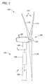
- FIG. 1 is a side elevation view of an exemplary wind turbine 100.
- wind turbine 100 is a horizontal axis wind turbine.
- wind turbine 100 may be a vertical axis wind turbine.
- Wind turbine 100 includes a tower 102 erected from a foundation (not shown), a nacelle 104 mounted on tower 102, and a rotor 108 rotatably coupled to nacelle 104.
- Tower 102 includes a plurality of tower sections 106 that are stacked atop of one another and are coupled together using a suitable coupler or fastener, such as a plurality of bolts, for example.
- tower sections 106 are substantially similar (e.g., are fabricated from substantially similar processes, as described below). In other embodiments, tower sections 106 may not be substantially similar.
- rotor 108 includes a rotatable hub 110 and a plurality of rotor blades 112 coupled to and extending outwardly from hub 110.
- rotor blades 112 include a first rotor blade 114, a second rotor blade 116, and a third rotor blade 118.
- rotor 108 may include any suitable number of rotor blades 112.
- rotor blades 112 are equidistantly spaced about hub 110 to facilitate enabling kinetic energy of the wind to be converted into rotational energy and, subsequently, into electrical energy.
- rotor blades 112 may be spaced any suitable distance from one another about hub 110.
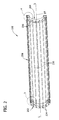
- FIG. 2 is an enlarged sectional view of tower section 106 shown in Figure 1 and taken along sectional line 2-2.
- Figure 3 is an enlarged portion of tower section 106 as shown in Figure 2 .
- Figure 4 is another enlarged portion of tower section 106 as shown in Figure 2 .
- tower section 106 has a longitudinal axis L and a radius R, and tower section 106 includes a first segment (e.g., a first flange 202), a second segment (e.g., a second flange 204), and a third segment (e.g., a wall section 206) extending from the first segment to the second segment along longitudinal axis L.
- tower section 106 is generally cylindrical.
- tower section 106 may have any suitable size and/or shape (e.g., tower section 106 may be tapered).
- first flange 202 is annular and includes a first mating surface 208, a first inner surface 210 adjacent first mating surface 208, a first support surface 212 adjacent first inner surface 210, and a first outer surface 214 between first mating surface 208 and first support surface 212, forming a substantially quadrilateral (e.g., rectangular) cross-section of first flange 202.
- second flange 204 is annular and includes a second mating surface 216, a second inner surface 218 adjacent second mating surface 216, a second support surface 220 adjacent second inner surface 218, and a second outer surface 222 between second mating surface 216 and second support surface 220, forming a substantially quadrilateral (e.g., rectangular) cross-section of second flange 204.
- First flange 202 has a first inner perimeter PI 1 defined by first inner surface 210 and a first outer perimeter PO 1 defined by first outer surface 214
- second flange 204 has a second inner perimeter PI 2 defined by second inner surface 218 and a second outer perimeter PO 2 defined by second outer surface 222.
- first flange 202 includes a plurality of first fastener apertures 224
- second flange 204 includes a plurality of second fastener apertures 226 that facilitate fastening tower section 106 to adjacent tower sections 106 via any suitable fastener (e.g., bolts).
- First fastener apertures 224 extend from first support surface 212 through first mating surface 208 in a predetermined pattern (e.g., a circumferential pattern in the exemplary embodiment) about first flange 202
- second fastener apertures 226 extend from second support surface 220 through second mating surface 216 in a predetermined pattern (e.g., a circumferential pattern in the exemplary embodiment) about second flange 204.
- first fastener apertures 224 and/or second fastener apertures 226 may be arranged in any suitable pattern.
- first flange 202 and/or second flange 204 may not include first fastener apertures 224 and/or second fastener apertures 226, respectively.
- first flange 202 and second flange 204 are fabricated from an ultra-high performance concrete ("UHPC").
- UHPC ultra-high performance concrete
- the term "ultra-high performance concrete" refers to a concrete material that has improved compression strength, tensile strength, and/or ductility over conventional concrete materials.
- the UHPC has a compression strength of between about 150 megapascals and about 300 megapascals and a tensile strength of between about 15 megapascals and 30 megapascals.
- the UHPC may have any suitable compression strength, tensile strength, and/or ductility that facilitates enabling the UHPC to function as described herein.
- first flange 202 and/or second flange 204 may be fabricated from any suitable material that enables tower section 106 to function as described herein, including, without limitation, another suitable concrete material.
- wall section 206 includes a first end surface 228, a second end surface 230, an interior surface 232, and an exterior surface 234.
- First end surface 228 is seated against first support surface 212 of first flange 202 adjacent first outer perimeter PO 1 such that first fastener apertures 224 (i.e., the circumferential pattern of first fastener apertures 224) are disposed radially between interior surface 232 of wall section 206 and first inner surface 210.
- second end surface 230 is seated against second support surface 220 of second flange 204 adjacent second outer perimeter PO 2 such that second fastener apertures 226 (i.e., the circumferential pattern of second fastener apertures 226) are disposed radially between interior surface 232 and second inner surface 218.
- wall section 206 may have any suitable radial positioning relative to first flange 202 and/or second flange 204 (e.g., wall section 206 may be positioned such that first fastener apertures 224 and/or second fastener apertures 226 are disposed between wall section 206 and outer surface 214 of flange 202 and/or outer surface 222 of flange 204).
- wall section 206 is fabricated from a concrete material.
- the concrete material of wall section 206 is different in composition than the UHPC of first flange 202 and/or second flange 204.
- the concrete material of wall section 206 may be at least substantially the same as the UHPC of first flange 202 and/or second flange 204.
- wall section 206 may be fabricated from any suitable material that enables tower section 106 to function as described herein.
- wall section 206 includes a plurality of pre-stressed, fiber reinforced plastic ("FRP") strands 236 (e.g., carbon fiber reinforced plastic (“CFRP”) strands) embedded therein.
- FRP strands 236 extend through wall section 206 along longitudinal axis L from first flange 202 to second flange 204 such that each FRP strand 236 extends through first support surface 212 into first flange 202 and/or through second support surface 220 and into second flange 204.
- FRP strands 236 are directly bonded to the concrete material of wall section 206 and are directly bonded to the UHPC of first flange 202 and second flange 204.
- FRP strands 236 may have any suitable engagement with first flange 202, second flange 204, and/or wall section 206 (e.g., an intermediate material may be disposed between FRP strands 236 and first flange 202, second flange 204, and/or wall section 206).
- FIG 5 is a perspective view of a flange formwork 300 suitable for use in fabricating first flange 202 and/or second flange 204.
- Figure 6 is a sectional view of flange formwork 300 taken along sectional line 6-6.
- flange formwork 300 is formed from an annular, wooden material that includes an inner wall 302, a mating wall 304 adjacent inner wall 302, an outer wall 306 adjacent mating wall 304, and a support wall 308 between outer wall 306 and inner wall 302, forming a cavity C having a substantially quadrilateral (e.g., rectangular) cross-section sized to match the substantially quadrilateral cross-section of first flange 202 and/or second flange 204.
- a substantially quadrilateral e.g., rectangular
- inner wall 302, mating wall 304, outer wall 306, and/or support wall 308 may be formed separately from one another and coupled together using any suitable fastener (e.g., screws, nails, and/or adhesives).
- inner wall 302, mating wall 304, outer wall 306, and/or support wall 308 may be integrally formed together (i.e., formed from a single, continuous, and unjointed material).
- flange formwork 300 may be formed from any suitable material and may have any suitable number of walls arranged in any suitable configuration (e.g., flange formwork 300 may have a shape other than an annular shape) that facilitates fabricating first flange 202 and/or second flange 204 as described herein having desired dimensions and/or configuration.
- support wall 308 includes a plurality of support wall strand apertures 310 extending therethrough
- mating wall 304 includes a plurality of mating wall strand apertures 312 extending therethrough.
- Support wall strand apertures 310 are arranged in a predetermined pattern (e.g., a circumferential pattern in the exemplary embodiment) about support wall 308, and mating wall strand apertures 312 are arranged in a predetermined pattern (e.g., a circumferential pattern in the exemplary embodiment) about mating wall 304 such that the circumferential pattern of mating wall strand apertures 312 substantially matches the circumferential pattern of support wall strand apertures 310 (i.e., each support wall strand aperture 310 is substantially coaxially aligned with a corresponding mating wall strand aperture 312 along an X-axis shown in Figure 6 ).
- flange formwork 300 also includes a plurality of fastener bosses 314 extending from support wall 308 to mating wall 304.
- Fastener bosses 314 are arranged in a circumferential pattern disposed radially between strand apertures 310, 312 and inner wall 302 (i.e., the circumferential pattern of fastener bosses 314 is positioned to generate the circumferential pattern of first fastener apertures 224 and/or second fastener apertures 226 through first flange 202 and/or second flange 204, as shown in Figure 2 ).
- Figures 7 and 8 are sectional views of a skeleton 400 suitable for use in fabricating tower section 106.
- skeleton 400 initially includes a first flange formwork 402, a second flange formwork 404, and a plurality of FRP strands 236 that extend from first flange formwork 402 to second flange formwork 404 substantially without tension.
- First flange formwork 402 and second flange formwork 404 are substantially similar to flange formwork 300 shown in Figure 5 , and similar components will be referenced using the same numerals of Figure 5 .
- a first portion 406 of each FRP strand 236 is disposed within cavity C of first flange formwork 402 by inserting each FRP strand 236 through first flange formwork 402 via one support wall strand aperture 310 and a corresponding, and substantially coaxial, mating wall strand aperture 312 and fastening each FRP strand 236 to an outer surface 412 of mating wall 304 of first flange formwork 402 (e.g., via knotting, stapling, etc.) to prevent or limit retraction of FRP strands 236 back through mating wall strand apertures 312 and/or support wall strand apertures 310.
- each FRP strand 236 is disposed within cavity C of second flange formwork 404 by inserting each FRP strand 236 through second flange formwork 404 via one support wall strand aperture 310 and a corresponding, and substantially coaxial, mating wall strand aperture 312 and fastening each FRP strand 236 to an outer surface 414 of mating wall 304 of second flange formwork 404 (e.g., via knotting, stapling, etc.) to prevent or limit retraction of FRP strands 236 back through mating wall strand apertures 312 and/or support wall strand apertures 310.
- first flange formwork 402 and/or second flange formwork 404 may not include inner wall 302, and the UHPC may be added into first flange formwork 402 and/or second flange formwork 404 via a spinning method (i.e., to facilitate obtaining a "spun-concrete").
- the UHPC may be added to first flange formwork 402 and/or second flange formwork 404 via any suitable method that enables formation of first flange 202 and second flange 204, respectively, from first flange formwork 402 and/or second flange formwork 404 as described herein.
- first flange formwork 402 and/or second flange formwork 404 the UHPC is permitted to harden into first flange 202 and second flange 204, respectively, as shown in Figure 8 (e.g., such that each of first flange 202 and/or second flange 204 is about 10-20 centimeters in thickness T and such that FRP strands 236 extend a distance D into and are directly bonded to the UHPC of first flange 202 and second flange 204).
- first portion 406 of each FRP strand extends through first flange 202 from first support surface 212 to first mating surface 208
- second portion 408 of each FRP strand 236 extends through second flange 204 from second support surface 220 to second mating surface 216
- a third portion 410 of each FRP strand 236 extends from first flange 202 to second flange 204.
- first flange 202 and/or second flange 204 may have any suitable thickness T, and first portion 406 and/or second portion 408 of FRP strands 236 may extend any suitable distance D into first flange 202 and/or second flange 204, respectively, that enables tower section 106 to function and/or to be fabricated as described herein.
- first flange form work 402 and second flange formwork 404 are removed, as shown in Figure 8 .
- first flange formwork 402 and/or second flange formwork 404 may remain coupled to first flange 202 and/or second flange 204, respectively, during at least one subsequent stage of fabrication of tower section 106.
- Figure 9 is a sectional view of skeleton 400 during a subsequent stage of fabrication of tower section 106.
- skeleton 400 is inserted into a frame 600 to facilitate applying tension to FRP strands 236, as described below.
- Frame 600 includes a base 602, a first sidewall 604 extending outwardly from base 602, and a second sidewall 606 extending outwardly from base 602.
- First sidewall 604 and second sidewall 606 include a plurality of frame apertures 608 arranged in a pattern that corresponds to the pattern of first fastener apertures 224 of first flange 202 and/or second fastener apertures 226 of second flange 204 (e.g., a circumferential pattern).
- frame 600 is fabricated from a rigid material (e.g., steel). In other embodiments, frame 600 may be fabricated from any suitable material that enables frame 600 to function as described herein.
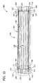
- first outer surface 214 of first flange 202 and second outer surface 222 of second flange 204 are raised above base 602 via a plurality of fasteners 610 (e.g., bolts) that are inserted through frame apertures 608 of sidewalls 604, 606 and into fastener apertures 224, 226 of first flange 202 and second flange 204, respectively, thereby engaging first flange 202 and second flange 204.
- fasteners 610 e.g., bolts
- Fasteners 610 are then tightened against first sidewall 604 and second sidewall 606 to facilitate displacing first flange 202 and second flange 204, respectively, toward first sidewall 604 in a direction D 1 and toward second sidewall 606 in a direction D 2 , respectively, (i.e., away from one another) thereby applying a desired tension to FRP strands 236.
- first portion 406 of each FRP strand 236 has a first tension
- second portion 408 of each FRP strand 236 has a second tension
- third portion 410 of each FRP strand 236 has a third tension such that the third tension is greater than the first tension and the second tension.
- first tension of first portion 406 and/or the second tension of second portion 408 may vary along distance D (e.g., may be substantially the same as the third tension of third portion 410 near third portion 410 and may be less than the third tension of third portion 410 away from third portion 410).
- first portion 406, second portion 408, and/or third portion 410 of each FRP strand 236 may have any suitable tension relative to one another (e.g., may be different than one another or substantially the same as one another).
- the UHPC of first flange 202 and second flange 204 in combination with the direct bonding between FRP strands 236 and flanges 202, 204, facilitates providing first flange 202 and second flange 204 with an increased tensile strength (e.g., an increased ability to withstand tensile stresses without cracking).
- This increased tensile strength is due, at least in part, to the strength of the direct bond between the UHPC and FRP strands 236, which enables higher tensile loads to be applied to FRP strands 236 via fasteners 610 during fabrication of tower section 106 with a reduced risk of cracking first flange 202 and/or second flange 204.
- FRP strands 236 extend distance D into first flange 202 and second flange 204 (e.g., substantially completely through first flange 202 and/or second flange 204 in some embodiments), a lateral (i.e., radial) force applied to FRP strands 236 by first flange 202 and/or second flange 204 (e.g., in reaction to the tensile stress applied to FRP strands 236 upon tightening fasteners 610) is facilitated to be distributed throughout a larger portion of first flange 202 and/or second flange 204, thereby enabling higher tensile loads to be applied to FRP strands 236 during fabrication of tower section 106 without breaking FRP strands 236.
- a lateral (i.e., radial) force applied to FRP strands 236 by first flange 202 and/or second flange 204 e.g., in reaction to the tensile stress applied to FRP
- Figure 10 is a sectional view of skeleton 400 inserted into frame 600 with the desired tension applied to FRP strands 236 and during a subsequent stage of fabrication of tower section 106.
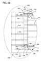
- Figure 11 is an enlarged sectional view of a portion of skeleton 400 and frame 600 as shown in Figure 10 .
- a wall formwork 700 is coupled to first flange 202 and second flange 204.
- wall formwork 700 includes an annular outer form 702 and an annular inner form 704.
- Inner form 704 includes a first end 706 and a second end 708, and outer form 702 includes a first end 710 and a second end 712.
- Inner form 704 is positioned between first flange 202 and second flange 204 such that inner form 704 is located radially between the circumferential patterns of fastener apertures 224, 226 and the circumferential arrangement of FRP strands 236 and such that first end 706 of inner form 704 abuts first support surface 212 of first flange 202 and second end 708 of inner form 704 abuts second support surface 220 of second flange 204.
- outer form 702 is positioned radially outward of FRP strands 236 such that outer form 702 is seated on outer surfaces 214, 222 of first flange 202 and second flange 204, respectively, and such that first end 710 of outer form 702 is substantially aligned with first mating surface 208 of first flange 202 and second end 712 of outer form 702 is substantially aligned with second mating surface 216 of second flange 204.
- wall formwork 700 may be extendable (e.g., telescopic) to facilitate protracting and/or retracting outer form 702 and/or inner form 704 between first flange 202 and second flange 204 (e.g., to facilitate using the same wall formwork 700 during fabrication of differently sized tower sections 106 and/or to facilitate easier insertion and/or removal of wall formwork 700 from between first flange 202 and/or second flange 204).
- extendable e.g., telescopic
- inner form 704 and/or outer form 702 may be positioned at any suitable location that facilitates enabling fabrication of tower section 106 as described herein.
- first flange formwork 402, second flange formwork 404, and/or wall formwork 700 may be a unitary structure (i.e., a single, continuous, and unjointed material) such that first flange 202, second flange 204, and/or wall section 206 are hardened before the unitary structure is removed.
- first flange formwork 402, second flange formwork 404, and/or wall formwork 700 are a unitary structure
- a temporary wall may be provided between cavities C and gap G during the forming (e.g., pouring and hardening) of first flange 202 and/or second flange 204 to facilitate preventing a flow of the UHPC into gap G.
- the concrete material is added into gap G between inner form 704 and outer form 702, and the concrete material is permitted to harden, thereby forming wall section 206 (shown in Figure 2 ).
- the concrete material is added into gap G with frame 600 oriented in a substantially horizontal position (e.g., with base 602 positioned on a planar surface, such as a ground surface or a table surface).
- the concrete material may be added into gap G via any suitable concrete injection method.
- wall formwork 700 may not include inner form 704, and the concrete material of wall section 206 may be added via a spinning method (e.g., skeleton 400 and/or frame 600 may be spun about longitudinal axis L to facilitate obtaining a "spun-concrete").
- the concrete material of wall section 206 may be added into gap G with frame 600 oriented in a vertical position.
- inner form 704 and outer form 702 are removed after the concrete material of wall section 206 has hardened. With inner form 704 and outer form 702 removed, tower section 106 is completely fabricated (as shown in Figure 2 ), and tower section 106 may be removed from frame 600.
- tower section 106 may subsequently be stacked with, and/or fastened to, adjacent tower sections 106 as shown in Figure 1 (e.g., by bolting adjacent tower sections 106 together via first fastener apertures 224 and/or second fastener apertures 226).
- wall section 206 and flanges 202, 204 are not bonded together but, rather, the tension applied to FRP strands 236 during fabrication of each tower section 106 and the weight of each tower section 106 atop of the other facilitate maintaining flanges 202, 204 and wall section 206 in abutment with one another (i.e., facilitate preventing flanges 202, 204 and/or wall section 206 from moving laterally relative to one another).
- an additional fastener e.g., a mechanical fastener and/or an adhesive fastener
- a mechanical fastener and/or an adhesive fastener may be provided to facilitate maintaining flanges 202, 204 and/or wall section 206 in proper position relative to one another during an operation of wind turbine 100.
- a plurality of shorter, unstressed FRP strands 236 may be embedded into flanges 202, 204 and wall section 206 during fabrication of tower section 106 such that the shorter, unstressed FRP strands 236 extend between flanges 202, 204 and wall section 206 to facilitate maintaining flanges 202, 204 and wall section 206 in abutment during an operation of wind turbine 100 (e.g., to facilitate preventing flanges 202, 204 and/or wall section 206 from moving laterally relative to one another).
- Figure 12 is a flow chart of a method 800 for fabricating or making a wind turbine tower as described herein.
- the method includes providing 802 at least one fiber reinforced plastic (FRP) strand, embedding 804 a first portion of the FRP strand into a first concrete segment, and embedding 806 a second portion of the FRP strand into a second concrete segment such that a third portion of the FRP strand extends from the first concrete segment to the second concrete segment.
- the method 800 also includes displacing 808 at least one of the first concrete segment and the second concrete segment relative to the other such that a tension is applied to the third portion of the FRP strand.
- Various of the methods and systems described herein facilitate providing a noncorrosive reinforcement for a tower such that the tower can be fabricated with a reduced thickness (e.g., a smaller layer of concrete surrounding the reinforcement), thereby decreasing an overall weight of the tower (and the individual tower sections) and enabling easier transportation of the tower to an erection site. Additionally, the methods and systems described herein facilitate strengthening the tower despite the reduced thickness (e.g., the methods and systems described herein facilitate increasing fatigue strength and tensile strength of the tower, which may facilitate decreasing a diameter of the tower proximate the nacelle).
- a reduced thickness e.g., a smaller layer of concrete surrounding the reinforcement
- Exemplary embodiments of a wind turbine tower and systems and methods for fabricating or making the same are described above in detail.
- the methods and systems described herein are not limited to the specific embodiments described herein, but rather, components of the systems and/or steps of the methods may be utilized independently and separately from other components and/or steps described herein.
- the methods and systems described herein may have other applications not limited to practice with wind turbines, as described herein. Rather, the methods and systems described herein can be implemented and utilized in connection with various other industries.
Landscapes
- Engineering & Computer Science (AREA)
- Architecture (AREA)
- Structural Engineering (AREA)
- Civil Engineering (AREA)
- Life Sciences & Earth Sciences (AREA)
- Chemical & Material Sciences (AREA)
- Sustainable Energy (AREA)
- General Engineering & Computer Science (AREA)
- Mechanical Engineering (AREA)
- Combustion & Propulsion (AREA)
- Sustainable Development (AREA)
- Materials Engineering (AREA)
- Wood Science & Technology (AREA)
- Wind Motors (AREA)
Applications Claiming Priority (1)
| Application Number | Priority Date | Filing Date | Title |
|---|---|---|---|
| US12/553,395 US8511013B2 (en) | 2009-09-03 | 2009-09-03 | Wind turbine tower and system and method for fabricating the same |
Publications (2)
| Publication Number | Publication Date |
|---|---|
| EP2305923A2 true EP2305923A2 (fr) | 2011-04-06 |
| EP2305923A3 EP2305923A3 (fr) | 2017-06-14 |
Family
ID=42221531
Family Applications (1)
| Application Number | Title | Priority Date | Filing Date |
|---|---|---|---|
| EP10173655.1A Withdrawn EP2305923A3 (fr) | 2009-09-03 | 2010-08-23 | Tour d'éolienne et système et procédé de fabrication associés |
Country Status (7)
| Country | Link |
|---|---|
| US (1) | US8511013B2 (fr) |
| EP (1) | EP2305923A3 (fr) |
| JP (1) | JP2011052692A (fr) |
| KR (1) | KR20110025147A (fr) |
| CN (1) | CN102011709A (fr) |
| AU (1) | AU2010214700A1 (fr) |
| CA (1) | CA2713522C (fr) |
Cited By (3)
| Publication number | Priority date | Publication date | Assignee | Title |
|---|---|---|---|---|
| CN102374134A (zh) * | 2010-08-18 | 2012-03-14 | 通用电气公司 | 带有转接区段的塔架 |
| DE102013108692A1 (de) * | 2013-08-12 | 2015-02-12 | Max Bögl Wind AG | Turm mit wenigstens einem Turmabschnitt mit Faserspanngliedern |
| CN112942954A (zh) * | 2019-12-10 | 2021-06-11 | 乌本产权有限公司 | 用于制造塔的区段的方法,被预紧的区段,塔环,塔,风能设施及预紧装置 |
Families Citing this family (29)
| Publication number | Priority date | Publication date | Assignee | Title |
|---|---|---|---|---|
| ES2378199B1 (es) * | 2009-06-24 | 2013-06-05 | Acciona Windpower S.A. | Sistema de unión de una góndola con la torre de hormigón de un aerogenerador. |
| IT1396433B1 (it) * | 2009-11-16 | 2012-11-23 | Rolic Invest Sarl | Impianto eolico per la generazione di energia elettrica e metodo per realizzare un pilone del suddetto impianto eolico. |
| US8468776B2 (en) * | 2010-06-16 | 2013-06-25 | Cortina Innovations S.A. de C.V. | Flange for wind power generators |
| US9016012B1 (en) * | 2011-05-23 | 2015-04-28 | Iowa State University Research Foundation, Inc. | Wind turbine tower system |
| ES2401787B2 (es) * | 2011-06-09 | 2014-01-21 | Inneo Torres, S.L. | Montaje machihembrado de fijación |
| DE102011078016A1 (de) * | 2011-06-22 | 2012-12-27 | Aloys Wobben | Turmfertigung |
| CN102425529B (zh) * | 2011-10-29 | 2013-12-11 | 邓允河 | 一种垂直轴风力发电机的现场安装方法 |
| EP2834435A1 (fr) * | 2012-04-04 | 2015-02-11 | Forida Development A/S | Turbine éolienne comprenant une partie de tour d'un composite renforcé de fibre ultra haute performance |
| EP4206413B1 (fr) * | 2012-09-17 | 2025-01-29 | Cpc Ag | Éléments de construction en béton précontraint et procédé de fabrication d'éléments de construction en béton précontraint |
| ES2471641B1 (es) * | 2012-12-21 | 2015-04-07 | Acciona Windpower, S.A. | Dovela prefabricada de hormigón, torre de aerogenerador que comprende dicha dovela, aerogenerador que comprende dicha torre y procedimiento de montaje de dicho aerogenerador |
| EP2781673B1 (fr) * | 2013-03-21 | 2016-03-16 | ALSTOM Renewable Technologies | Tour |
| US9574349B2 (en) * | 2013-05-13 | 2017-02-21 | Hawkeye Pedershaab Concrete Technologies, Inc. | Post-tensioning concrete pipe wrap |
| CN103375043B (zh) * | 2013-07-17 | 2015-12-23 | 上海交通大学 | 一种预应力超高性能混凝土海上风电塔架 |
| PL2846040T3 (pl) * | 2013-09-06 | 2018-09-28 | youWINenergy GmbH | Zespół wieży dla instalacji turbiny wiatrowej |
| CN103669973A (zh) * | 2013-12-03 | 2014-03-26 | 国网河南省电力公司商丘供电公司 | 高弯矩碳纤维混凝土线杆及制作方法 |
| ES2538734B1 (es) * | 2013-12-20 | 2016-05-10 | Acciona Windpower, S.A. | Procedimiento de montaje de torres de hormigón de sección troncocónica y torre de hormigón montada con dicho procedimiento |
| ES2545038B1 (es) * | 2014-03-07 | 2016-04-26 | Inneo Torres, S.L. | Sistema constructivo para torres eólicas |
| EP2942453A1 (fr) * | 2014-05-05 | 2015-11-11 | Siemens Aktiengesellschaft | Tour éolienne et son procédé de production |
| DE102014209857A1 (de) * | 2014-05-23 | 2015-11-26 | Wobben Properties Gmbh | Windenergieanlagen-Turm und Verfahren zum Errichten eines Windenergieanlagen-Turms |
| US11536045B2 (en) * | 2014-10-30 | 2022-12-27 | Byo Towers, S.L. | Method for installing a hollow concrete tower made from more than one segment and corresponding hollow concrete tower |
| EP3212862B1 (fr) * | 2014-10-31 | 2019-04-24 | Soletanche Freyssinet | Procédé de fabrication de blocs de construction en béton pour une tour d'aérogénérateur et système associé |
| FR3029231B1 (fr) * | 2014-12-01 | 2016-12-30 | Lafarge Sa | Section en beton |
| CN113738586A (zh) * | 2015-08-31 | 2021-12-03 | 西门子歌美飒可再生能源有限公司 | 具有混凝土底座的设备塔架 |
| DE202016009246U1 (de) * | 2015-09-15 | 2026-01-28 | Max Bögl Wind AG | Turm für eine Windkraftanlage aus ringsegmentförmigen Betonfertigteilen |
| EP3246493A1 (fr) * | 2016-05-17 | 2017-11-22 | Holcim Technology Ltd. | Procédé de construction d'un mât pour une éolienne |
| EP3987179B1 (fr) * | 2019-06-21 | 2024-06-26 | Vestas Wind Systems A/S | Améliorations relatives au renforcement des tours d'éoliennes |
| EP3926164A1 (fr) * | 2020-06-19 | 2021-12-22 | Vestas Offshore Wind A/S | Dispositif et procédé d'assemblage d'éolienne |
| CN118510993A (zh) * | 2021-11-23 | 2024-08-16 | 格雷戈里·约翰·内伯尔斯 | 伸长构件、其构造方法及其设备 |
| JP2023135028A (ja) * | 2022-03-15 | 2023-09-28 | 日本ヒューム株式会社 | プレキャスト部材 |
Family Cites Families (38)
| Publication number | Priority date | Publication date | Assignee | Title |
|---|---|---|---|---|
| US909299A (en) * | 1908-05-22 | 1909-01-12 | Herbert H Hilborn | Method of reinforcing tubular structures. |
| SE415992B (sv) * | 1977-02-07 | 1980-11-17 | A Betong Ab | Sett att tillverka en armeringsbur till betongstoplr jemte fixtur for utforande av settet |
| US4910940A (en) * | 1977-08-29 | 1990-03-27 | Grady Ii Clyde C | Modular structural arrays |
| US5218810A (en) * | 1992-02-25 | 1993-06-15 | Hexcel Corporation | Fabric reinforced concrete columns |
| DE4313227A1 (de) | 1993-04-22 | 1994-10-27 | Horst Dr Ing Kinkel | Vorgespanntes Bewehrungselement |
| US5599599A (en) * | 1995-07-06 | 1997-02-04 | University Of Central Florida | Fiber reinforced plastic ("FRP")-concrete composite structural members |
| US6082063A (en) * | 1996-11-21 | 2000-07-04 | University Technologies International Inc. | Prestressing anchorage system for fiber reinforced plastic tendons |
| US6123485A (en) * | 1998-02-03 | 2000-09-26 | University Of Central Florida | Pre-stressed FRP-concrete composite structural members |
| DE19823650C2 (de) * | 1998-05-27 | 2001-05-23 | Wilfried Arand | Verfahren und Vorrichtung zum Herstellen von hohen, hohlen, turmartigen Bauwerken von bis zu zweihundert Metern Höhe und mehr, insbesondere von Türmen für Windkraftanlagen |
| JP2000283018A (ja) * | 1999-03-30 | 2000-10-10 | Fuji Heavy Ind Ltd | 水平軸風車及び該水平軸風車の建設方法 |
| JP2000283019A (ja) * | 1999-03-31 | 2000-10-10 | Pc Bridge Co Ltd | コンクリート製風車支持タワー及びその構築方法 |
| US6305140B1 (en) * | 1999-09-07 | 2001-10-23 | Lenard Knight | Pole |
| DE10033845A1 (de) * | 2000-07-12 | 2002-01-24 | Aloys Wobben | Turm aus Spannbeton-Fertigteilen |
| US6467233B1 (en) * | 2000-11-09 | 2002-10-22 | Beaird Industries, Inc | Wind tower |
| US6532700B1 (en) * | 2000-11-09 | 2003-03-18 | Beaird Industries, Inc. | Flange with cut for wind tower |
| US6811861B2 (en) * | 2000-11-28 | 2004-11-02 | Wisconsin Alumni Research Foundation | Structural reinforcement using composite strips |
| EP1396321A4 (fr) | 2001-05-24 | 2006-04-05 | Japan Science & Tech Agency | Procede de fabrication de beton precontraint |
| US6851231B2 (en) * | 2001-06-27 | 2005-02-08 | Maher K. Tadros | Precast post-tensioned segmental pole system |
| US6898908B2 (en) | 2002-03-06 | 2005-05-31 | Oldcastle Precast, Inc. | Insulative concrete building panel with carbon fiber and steel reinforcement |
| US6938392B2 (en) * | 2002-08-14 | 2005-09-06 | Newmark International, Inc. | Concrete filled pole |
| JP2004077244A (ja) | 2002-08-14 | 2004-03-11 | Mitsubishi Heavy Ind Ltd | 繊維強化コンクリートキャスク及びその成型用支持枠体、該コンクリートキャスクの製造方法 |
| JP4355949B2 (ja) * | 2002-10-01 | 2009-11-04 | ゼネラル・エレクトリック・カンパニイ | 風力タービンタワー用のモジュラーキット |
| US20040071372A1 (en) * | 2002-10-15 | 2004-04-15 | Osmun Richard Lee | Rocking hinge bearing system for isolating structures from dynamic/seismic loads |
| US20050183381A1 (en) * | 2003-01-21 | 2005-08-25 | Rosenberg Jean G. | Method for manufacturing brakeless lightweight concrete poles |
| CA2519277C (fr) * | 2003-03-19 | 2011-07-12 | Vestas Wind Systems A/S | Procede de construction de grandes tours destinees a des turbines eoliennes |
| EP1634999B1 (fr) * | 2003-06-02 | 2007-06-13 | Yurkevich Engineering Bureau LTD | Colonne en beton arme placee dans une excavation et procede d'erection correspondant |
| US7253786B1 (en) * | 2003-06-04 | 2007-08-07 | Rocco Logozzo | Reinforced monopole construction |
| AT413042B (de) * | 2003-12-19 | 2005-10-15 | Rund Stahl Bau Gmbh & Co | Innenschalungsabschnitt zur errichtung eines bauwerksabschnitts |
| FR2866330B1 (fr) * | 2004-02-13 | 2006-08-18 | Eiffage Tp | Beton ultra haute performance et autoplacant, son procede de preparation et son utilisation. |
| US7426807B2 (en) * | 2004-03-03 | 2008-09-23 | Charles E Cadwell | Composite telephone pole |
| US7762041B1 (en) * | 2004-11-03 | 2010-07-27 | Valmont Newmark, Inc. | Hybrid metal pole |
| ES2246734B1 (es) | 2005-04-21 | 2007-04-16 | STRUCTURAL CONCRETE & STEEL, S.L. | Torre modular prefabricada. |
| WO2007012201A1 (fr) * | 2005-07-25 | 2007-02-01 | The University Of Manitoba | Systèmes de tours éoliennes composites et procédés de fabrication |
| ES2326010B2 (es) * | 2006-08-16 | 2011-02-18 | Inneo21, S.L. | Estructura y procedimiento de montaje de torres de hormigon para turbinas eolicas. |
| PT103562B (pt) * | 2006-09-13 | 2008-08-14 | Alexandre Francisco Mal Aragao | Torres em betão polimérico para geradores eólicos e outras grandes aplicações estruturais |
| JP5096029B2 (ja) * | 2007-03-29 | 2012-12-12 | 株式会社ピーエス三菱 | コンクリート製塔状構造物及びその製造方法 |
| US20080236073A1 (en) * | 2007-03-30 | 2008-10-02 | General Electric Company | Low cost rail-transportable wind turbine tower |
| WO2009056898A1 (fr) * | 2007-11-02 | 2009-05-07 | Alejandro Cortina-Cordero | Tour en béton postcontraint pour génératrices éoliennes |
-
2009
- 2009-09-03 US US12/553,395 patent/US8511013B2/en not_active Expired - Fee Related
-
2010
- 2010-08-23 EP EP10173655.1A patent/EP2305923A3/fr not_active Withdrawn
- 2010-08-26 CA CA2713522A patent/CA2713522C/fr not_active Expired - Fee Related
- 2010-08-27 JP JP2010190211A patent/JP2011052692A/ja not_active Ceased
- 2010-08-27 AU AU2010214700A patent/AU2010214700A1/en not_active Abandoned
- 2010-09-02 KR KR1020100086065A patent/KR20110025147A/ko not_active Withdrawn
- 2010-09-03 CN CN2010102871418A patent/CN102011709A/zh active Pending
Non-Patent Citations (1)
| Title |
|---|
| None |
Cited By (7)
| Publication number | Priority date | Publication date | Assignee | Title |
|---|---|---|---|---|
| CN102374134A (zh) * | 2010-08-18 | 2012-03-14 | 通用电气公司 | 带有转接区段的塔架 |
| CN102374134B (zh) * | 2010-08-18 | 2015-07-08 | 通用电气公司 | 带有转接区段的塔架 |
| DE102013108692A1 (de) * | 2013-08-12 | 2015-02-12 | Max Bögl Wind AG | Turm mit wenigstens einem Turmabschnitt mit Faserspanngliedern |
| CN112942954A (zh) * | 2019-12-10 | 2021-06-11 | 乌本产权有限公司 | 用于制造塔的区段的方法,被预紧的区段,塔环,塔,风能设施及预紧装置 |
| EP3845354A2 (fr) | 2019-12-10 | 2021-07-07 | Wobben Properties GmbH | Procédé de fabrication de segments pour une tour, segment précontraint, anneau de tour, tour, éolienne ainsi que dispositif de précontrainte |
| EP3845354A3 (fr) * | 2019-12-10 | 2021-09-15 | Wobben Properties GmbH | Procédé de fabrication de segments pour une tour, segment précontraint, anneau de tour, tour, éolienne ainsi que dispositif de précontrainte |
| US11566605B2 (en) | 2019-12-10 | 2023-01-31 | Wobben Properties Gmbh | Method for manufacturing segments for a tower, prestressed segment, tower ring, tower, wind turbine, and prestressing device |
Also Published As
| Publication number | Publication date |
|---|---|
| EP2305923A3 (fr) | 2017-06-14 |
| US20100132282A1 (en) | 2010-06-03 |
| AU2010214700A1 (en) | 2011-03-17 |
| KR20110025147A (ko) | 2011-03-09 |
| JP2011052692A (ja) | 2011-03-17 |
| CA2713522C (fr) | 2017-10-10 |
| CN102011709A (zh) | 2011-04-13 |
| CA2713522A1 (fr) | 2011-03-03 |
| US8511013B2 (en) | 2013-08-20 |
Similar Documents
| Publication | Publication Date | Title |
|---|---|---|
| US8511013B2 (en) | Wind turbine tower and system and method for fabricating the same | |
| EP2420639B1 (fr) | Tour avec section adaptatrice | |
| EP2541047B1 (fr) | Procédé d'assemblage d'éoliennes et éolienne assemblée selon ce procédé | |
| EP2402529A2 (fr) | Tour avec câbles d'ancrage | |
| US7805895B2 (en) | Foundation for enabling anchoring of a wind turbine tower thereto by means of replaceable through-bolts | |
| EP3111022B1 (fr) | Tour de béton composite hybride pour une éolienne et procédé de fabrication | |
| CN100570108C (zh) | 预制模块式塔 | |
| US20180128246A1 (en) | Wind turbine comprising a tower part of an ultra-high performance fiber reinforced composite | |
| KR20110004797A (ko) | 윈드 터빈 스페이스 프레임 타워용의 모듈형 지상 기초부 | |
| CN112654747A (zh) | 用于风力设备的基座 | |
| CN111456909A (zh) | 中心筒构件、具有其的中心筒和塔筒基础 | |
| CN111594390B (zh) | 将塔架连接到基座的方法 | |
| JP4874152B2 (ja) | プレキャスト工法による変断面塔状構造物 | |
| EP3055560A1 (fr) | Dispositif de support et procédés pour améliorer et construire un dispositif de support | |
| US12305348B2 (en) | Foundation for an offshore structure | |
| US20230003046A1 (en) | Wind turbine and method for manufacturing a wind turbine tower |
Legal Events
| Date | Code | Title | Description |
|---|---|---|---|
| PUAI | Public reference made under article 153(3) epc to a published international application that has entered the european phase |
Free format text: ORIGINAL CODE: 0009012 |
|
| AK | Designated contracting states |
Kind code of ref document: A2 Designated state(s): AL AT BE BG CH CY CZ DE DK EE ES FI FR GB GR HR HU IE IS IT LI LT LU LV MC MK MT NL NO PL PT RO SE SI SK SM TR |
|
| AX | Request for extension of the european patent |
Extension state: BA ME RS |
|
| RIC1 | Information provided on ipc code assigned before grant |
Ipc: E04H 12/16 20060101ALI20170125BHEP Ipc: E04C 5/08 20060101ALI20170125BHEP Ipc: E04H 12/34 20060101ALI20170125BHEP Ipc: E04C 5/07 20060101AFI20170125BHEP |
|
| PUAL | Search report despatched |
Free format text: ORIGINAL CODE: 0009013 |
|
| AK | Designated contracting states |
Kind code of ref document: A3 Designated state(s): AL AT BE BG CH CY CZ DE DK EE ES FI FR GB GR HR HU IE IS IT LI LT LU LV MC MK MT NL NO PL PT RO SE SI SK SM TR |
|
| AX | Request for extension of the european patent |
Extension state: BA ME RS |
|
| RIC1 | Information provided on ipc code assigned before grant |
Ipc: E04C 5/08 20060101ALI20170505BHEP Ipc: E04C 5/07 20060101AFI20170505BHEP Ipc: E04G 11/20 20060101ALI20170505BHEP Ipc: E04H 12/12 20060101ALI20170505BHEP Ipc: E04H 12/16 20060101ALI20170505BHEP Ipc: E04H 12/34 20060101ALI20170505BHEP |
|
| 17P | Request for examination filed |
Effective date: 20171214 |
|
| RBV | Designated contracting states (corrected) |
Designated state(s): AL AT BE BG CH CY CZ DE DK EE ES FI FR GB GR HR HU IE IS IT LI LT LU LV MC MK MT NL NO PL PT RO SE SI SK SM TR |
|
| RIC1 | Information provided on ipc code assigned before grant |
Ipc: E04G 11/20 20060101ALI20180430BHEP Ipc: E04C 5/08 20060101ALI20180430BHEP Ipc: E04H 12/12 20060101ALI20180430BHEP Ipc: E04H 12/34 20060101ALI20180430BHEP Ipc: E04H 12/16 20060101ALI20180430BHEP Ipc: E04C 5/07 20060101AFI20180430BHEP |
|
| GRAP | Despatch of communication of intention to grant a patent |
Free format text: ORIGINAL CODE: EPIDOSNIGR1 |
|
| RIC1 | Information provided on ipc code assigned before grant |
Ipc: E04H 12/16 20060101AFI20180802BHEP Ipc: E04H 12/12 20060101ALI20180802BHEP Ipc: E04C 5/08 20060101ALI20180802BHEP Ipc: E04H 12/34 20060101ALI20180802BHEP Ipc: F03D 13/20 20160101ALI20180802BHEP Ipc: E04C 5/07 20060101ALI20180802BHEP |
|
| INTG | Intention to grant announced |
Effective date: 20180816 |
|
| RIN1 | Information on inventor provided before grant (corrected) |
Inventor name: VOSS, STEFAN |
|
| STAA | Information on the status of an ep patent application or granted ep patent |
Free format text: STATUS: THE APPLICATION IS DEEMED TO BE WITHDRAWN |
|
| 18D | Application deemed to be withdrawn |
Effective date: 20190103 |