EP2306321A1 - Erhöhung der Speicherleistung in Flash-Speichervorrichtungen mittels gleichzeitiger Durchführung des Schreibvorgangs auf mehreren Vorrichtungen - Google Patents
Erhöhung der Speicherleistung in Flash-Speichervorrichtungen mittels gleichzeitiger Durchführung des Schreibvorgangs auf mehreren Vorrichtungen Download PDFInfo
- Publication number
- EP2306321A1 EP2306321A1 EP10012048A EP10012048A EP2306321A1 EP 2306321 A1 EP2306321 A1 EP 2306321A1 EP 10012048 A EP10012048 A EP 10012048A EP 10012048 A EP10012048 A EP 10012048A EP 2306321 A1 EP2306321 A1 EP 2306321A1
- Authority
- EP
- European Patent Office
- Prior art keywords
- information
- sector
- volatile memory
- memory unit
- bus
- Prior art date
- Legal status (The legal status is an assumption and is not a legal conclusion. Google has not performed a legal analysis and makes no representation as to the accuracy of the status listed.)
- Granted
Links
Images


Classifications
-
- G—PHYSICS
- G11—INFORMATION STORAGE
- G11C—STATIC STORES
- G11C16/00—Erasable programmable read-only memories
- G11C16/02—Erasable programmable read-only memories electrically programmable
- G11C16/06—Auxiliary circuits, e.g. for writing into memory
- G11C16/10—Programming or data input circuits
- G11C16/102—External programming circuits, e.g. EPROM programmers; In-circuit programming or reprogramming; EPROM emulators
-
- G—PHYSICS
- G06—COMPUTING OR CALCULATING; COUNTING
- G06F—ELECTRIC DIGITAL DATA PROCESSING
- G06F12/00—Accessing, addressing or allocating within memory systems or architectures
- G06F12/02—Addressing or allocation; Relocation
- G06F12/0223—User address space allocation, e.g. contiguous or non contiguous base addressing
- G06F12/023—Free address space management
- G06F12/0238—Memory management in non-volatile memory, e.g. resistive RAM or ferroelectric memory
- G06F12/0246—Memory management in non-volatile memory, e.g. resistive RAM or ferroelectric memory in block erasable memory, e.g. flash memory
-
- G—PHYSICS
- G06—COMPUTING OR CALCULATING; COUNTING
- G06F—ELECTRIC DIGITAL DATA PROCESSING
- G06F3/00—Input arrangements for transferring data to be processed into a form capable of being handled by the computer; Output arrangements for transferring data from processing unit to output unit, e.g. interface arrangements
- G06F3/06—Digital input from, or digital output to, record carriers, e.g. RAID, emulated record carriers or networked record carriers
- G06F3/0601—Interfaces specially adapted for storage systems
- G06F3/0602—Interfaces specially adapted for storage systems specifically adapted to achieve a particular effect
- G06F3/061—Improving I/O performance
- G06F3/0613—Improving I/O performance in relation to throughput
-
- G—PHYSICS
- G06—COMPUTING OR CALCULATING; COUNTING
- G06F—ELECTRIC DIGITAL DATA PROCESSING
- G06F3/00—Input arrangements for transferring data to be processed into a form capable of being handled by the computer; Output arrangements for transferring data from processing unit to output unit, e.g. interface arrangements
- G06F3/06—Digital input from, or digital output to, record carriers, e.g. RAID, emulated record carriers or networked record carriers
- G06F3/0601—Interfaces specially adapted for storage systems
- G06F3/0628—Interfaces specially adapted for storage systems making use of a particular technique
- G06F3/0638—Organizing or formatting or addressing of data
- G06F3/064—Management of blocks
-
- G—PHYSICS
- G06—COMPUTING OR CALCULATING; COUNTING
- G06F—ELECTRIC DIGITAL DATA PROCESSING
- G06F3/00—Input arrangements for transferring data to be processed into a form capable of being handled by the computer; Output arrangements for transferring data from processing unit to output unit, e.g. interface arrangements
- G06F3/06—Digital input from, or digital output to, record carriers, e.g. RAID, emulated record carriers or networked record carriers
- G06F3/0601—Interfaces specially adapted for storage systems
- G06F3/0628—Interfaces specially adapted for storage systems making use of a particular technique
- G06F3/0655—Vertical data movement, i.e. input-output transfer; data movement between one or more hosts and one or more storage devices
- G06F3/0658—Controller construction arrangements
-
- G—PHYSICS
- G06—COMPUTING OR CALCULATING; COUNTING
- G06F—ELECTRIC DIGITAL DATA PROCESSING
- G06F3/00—Input arrangements for transferring data to be processed into a form capable of being handled by the computer; Output arrangements for transferring data from processing unit to output unit, e.g. interface arrangements
- G06F3/06—Digital input from, or digital output to, record carriers, e.g. RAID, emulated record carriers or networked record carriers
- G06F3/0601—Interfaces specially adapted for storage systems
- G06F3/0668—Interfaces specially adapted for storage systems adopting a particular infrastructure
- G06F3/0671—In-line storage system
- G06F3/0673—Single storage device
- G06F3/0679—Non-volatile semiconductor memory device, e.g. flash memory, one time programmable memory [OTP]
-
- G—PHYSICS
- G11—INFORMATION STORAGE
- G11C—STATIC STORES
- G11C16/00—Erasable programmable read-only memories
- G11C16/02—Erasable programmable read-only memories electrically programmable
- G11C16/06—Auxiliary circuits, e.g. for writing into memory
- G11C16/08—Address circuits; Decoders; Word-line control circuits
-
- G—PHYSICS
- G11—INFORMATION STORAGE
- G11C—STATIC STORES
- G11C29/00—Checking stores for correct operation ; Subsequent repair; Testing stores during standby or offline operation
- G11C29/70—Masking faults in memories by using spares or by reconfiguring
- G11C29/76—Masking faults in memories by using spares or by reconfiguring using address translation or modifications
- G11C29/765—Masking faults in memories by using spares or by reconfiguring using address translation or modifications in solid state disks
-
- G—PHYSICS
- G11—INFORMATION STORAGE
- G11C—STATIC STORES
- G11C29/00—Checking stores for correct operation ; Subsequent repair; Testing stores during standby or offline operation
- G11C29/70—Masking faults in memories by using spares or by reconfiguring
- G11C29/78—Masking faults in memories by using spares or by reconfiguring using programmable devices
- G11C29/80—Masking faults in memories by using spares or by reconfiguring using programmable devices with improved layout
- G11C29/816—Masking faults in memories by using spares or by reconfiguring using programmable devices with improved layout for an application-specific layout
- G11C29/82—Masking faults in memories by using spares or by reconfiguring using programmable devices with improved layout for an application-specific layout for EEPROMs
-
- G—PHYSICS
- G06—COMPUTING OR CALCULATING; COUNTING
- G06F—ELECTRIC DIGITAL DATA PROCESSING
- G06F11/00—Error detection; Error correction; Monitoring
- G06F11/07—Responding to the occurrence of a fault, e.g. fault tolerance
- G06F11/08—Error detection or correction by redundancy in data representation, e.g. by using checking codes
- G06F11/10—Adding special bits or symbols to the coded information, e.g. parity check, casting out 9's or 11's
- G06F11/1008—Adding special bits or symbols to the coded information, e.g. parity check, casting out 9's or 11's in individual solid state devices
- G06F11/1068—Adding special bits or symbols to the coded information, e.g. parity check, casting out 9's or 11's in individual solid state devices in sector programmable memories, e.g. flash disk
-
- G—PHYSICS
- G06—COMPUTING OR CALCULATING; COUNTING
- G06F—ELECTRIC DIGITAL DATA PROCESSING
- G06F2212/00—Indexing scheme relating to accessing, addressing or allocation within memory systems or architectures
- G06F2212/10—Providing a specific technical effect
- G06F2212/1016—Performance improvement
-
- G—PHYSICS
- G06—COMPUTING OR CALCULATING; COUNTING
- G06F—ELECTRIC DIGITAL DATA PROCESSING
- G06F2212/00—Indexing scheme relating to accessing, addressing or allocation within memory systems or architectures
- G06F2212/72—Details relating to flash memory management
- G06F2212/7203—Temporary buffering, e.g. using volatile buffer or dedicated buffer blocks
-
- G—PHYSICS
- G06—COMPUTING OR CALCULATING; COUNTING
- G06F—ELECTRIC DIGITAL DATA PROCESSING
- G06F2212/00—Indexing scheme relating to accessing, addressing or allocation within memory systems or architectures
- G06F2212/72—Details relating to flash memory management
- G06F2212/7208—Multiple device management, e.g. distributing data over multiple flash devices
Definitions
- This invention relates to the field of digital systems, such as personal computers and digital cameras, employing nonvolatile memory as mass storage, for use in replacing hard disk storage or conventional film. More particularly, this invention relates to an architecture for increasing the performance of such digital systems by increasing the rate at which digital information is read from and written to the nonvolatile memory.
- nonvolatile memory such as flash or EEPROM memory
- flash or EEPROM memory many digital systems have replaced conventional mass storage devices with flash and/or EEPROM memory devices.
- PC s personal computers
- solid state storage devices for mass storage purposes in place of conventional hard disks.
- Digital cameras employ solid state storage devices in cards to replace conventional films.
- Fig. 1 shows a prior art memory system 10 including a controller 12, which is generally a semiconductor (or integrated circuit) device, coupled to a host 14 which may be a PC or a digital camera.
- the controller 12 is further coupled to a nonvolatile memory bank 16.
- Host 14 writes and reads information, organized in sectors, to and from memory bank 16 which includes a first nonvolatile memory chip 18 and a second nonvolatile memory chip 20.
- Chip 18 includes: an I/O register 22 having a port 24 connected to a port 26 of controller 12 via a first bus 28 which includes 8 bit lines; and a storage area 30 coupled with I/O register 22.
- Chip 20 includes: an I/O register 32 having a port 34 connected to a port 36 of controller 12 via a second bus 38 which includes 8 bit lines; and a storage area 40 coupled with I/O register 32.
- the first and second buses 28, 38 are used to transmit data, address, and command signals between the controller and the memory chips 18 and 20.
- the least significant 8 bits (LSBs) of 16 bits of information are provided to chip 18 via the first bus 28, and the most significant 8 bits (MSBs) are provided to the chip 20 via the second bus 38.
- Memory bank 16 includes a plurality of block locations 42 each of which includes a plurality of memory row locations.
- Each block location of the memory bank is comprised of a first sub-block 44 located in the first non-volatile memory chip, and a corresponding second sub-block 46 located in the second non-volatile memory chip.
- Each memory row location includes a first row-portion 48 and a corresponding second row-portion 50.
- each of the first and second row-portions 48 and 50 includes storage for 256 bytes of data information plus an additional 8 bytes of storage space for overhead information.
- a sector includes 512 bytes of user data and 16 bytes of non-user data (the latter commonly referred to as overhead information)
- 256 bytes of the user data and 8 bytes of the overhead information of the sector may be maintained in the first row portion 48 of chip 18 and the remaining 256 bytes of user data and remaining 8 bytes of overhead information of the same sector may be maintained in the second row portion 50 of chip 20.
- half of a sector is stored in a memory row location 48 of chip 18 and the other half of the sector is stored in memory row location 50 of chip 20.
- half of the overhead information of each stored sector is maintained by chip 18 and the other half by chip 20.
- reading and writing data to flash memory chips 18 and 20 is time consuming.
- Writing data to the flash memory chips is particularly time consuming because data must be latched in I/O registers 22 and 32, which are loaded 1 byte at a time via the first and second buses, and then transferred from the I/O registers 22 and 32 to the memory cells of the flash memory chips 18 and 20 respectively.
- the time required to transfer data from the I/O registers to memory, per byte of data, is proportional to the size of the I/O registers and the size of the flash memory chip.
- controller 12 writes a single sector of information to memory bank 16 by: (1) transmitting a write command signal to each of chips 18 and 20 via buses 28 and 38 simultaneously; (2) transmitting address data to chips 18 and 20 specifying corresponding sub-blocks 44 and 46 of the chips via buses 28 and 38 simultaneously; and (3) sequentially transmitting a byte of user data to each of chips 18 and 20 via buses 28 and 38 simultaneously for storage in the corresponding sub-blocks 44 and 46.
- the problem with such prior art systems is that while two bytes of information are written and read at a time, only one sector of information is accommodated at a time by the memory bank 16 during a write command initiated by the host 14.
- FIG. 2 Another prior art digital system 60 is shown in Fig. 2 to include a controller 62 coupled to a host 64, and a nonvolatile memory bank 66 for storing and reading information organized in sectors to and from nonvolatile memory chip 68, included in the memory bank 66. While not shown, more chips may be included in the memory bank, although the controller, upon command by the host, stores an entire sector in one chip.
- a block, such as block 0, includes 16 sectors S0, S1,..., S 15.
- Also included in the chip 68 is an I/O register 70, which includes 512 bytes plus 16 bytes, a total of 528 bytes, of storage space. The controller transfers information between host 64 and memory 66 a byte at-a-time.
- a sector of 512 bytes of user data plus 16 bytes of overhead information is temporarily stored in the I/O register during a write operation and then transferred to one of the blocks within the memory device for storage thereof.
- a sector of information is read from one of the blocks of the memory device and then stored in the I/O register for transfer to the controller .
- An important problem with the prior art architecture of Fig. 2 is that while a total of 528 bytes may be stored in the I/O register 36, only one byte of sector information may be transferred at a time between the controller and the memory bank thereby impeding the overall performance of the system.
- Both of the prior art systems of Figs. 1 and 2 maintain LBA to PBA mapping information for translating a host-provided logical block address (LBA) identifying a sector of information to a physical block address (PBA) identifying the location of a sector within the memory bank.
- LBA logical block address
- PBA physical block address
- This mapping information may generally be included in volatile memory, such as a RAM, within the controller, although it may be maintained outside of the controller.
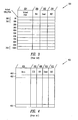
- Fig. 3 shows a table diagram illustrating an example of an LBA-PBA map 300 defined by rows and columns, with each row 302 being uniquely identified, addressed, by a value equal to that of the LBA received from the host divided by 16.
- the row numbers of Fig. 3 are shown using hexadecimal notation. Thus, for example, row 10H (in Hex.) has an address value equal to 16 in decimal.
- Each row 302 of map 300 includes a storage location field 304 for maintaining a virtual PBA value, an 'old' flag field 306, a 'used' flag field 308, and a 'defect' flag field 310.
- the flag fields provide information relating to the status of a block of information maintained within the memory bank (in Figs. 1 and 2 ).
- the virtual PBA field 304 stores information regarding the location of the block within the memory bank.
- Fig. 4 shows a table diagram illustrating an exemplary format for storage of a sector of data maintained in a memory bank.
- the virtual PBA field 304 ( Fig. 3 ) provides information regarding the location of a block 400 of information with each block having a plurality of sectors 402.
- Each sector 402 is comprised of a user data field 404, an ECC field 406, an 'old' flag field 408, a 'used' flag field 410 and a 'defect' flag field 412.
- table 300 occupies much 'real estate' and since it is commonly comprised of RAM technology, which is in itself costly and generally kept within the controller, there is substantial costs associated with its manufacturing. Furthermore, as each row of table 300 is associated with one block of information, the larger the number of blocks of information, the larger the size of the table, which is yet an additional cost for manufacturing the controller and therefore the digital system employing such a table.
- the present invention includes a digital system having a controller semiconductor device coupled to a host and a nonvolatile memory bank including a plurality of nonvolatile memory devices.
- the controller transfers information, organized in sectors, with each sector including a user data portion and an overhead portion, between the host and the nonvolatile memory bank and stores and reads two bytes of information relating to the same sector simultaneously within two nonvolatile memory devices.
- Each nonvolatile memory device is defined by a row of memory locations wherein corresponding rows of at least two semiconductor devices maintain two sectors of information therein with the overhead information relating to the two sectors maintained in one of the memory rows of the nonvolatile memory device.
- Each 32 sectors of information defines a block identified by a virtual physical block address with a block of information expanding between two memory devices wherein an even and an odd byte of a sector is simultaneously read from or written to two nonvolatile memory devices.
- the controller stores an entire sector of information within a single nonvolatile memory device and reads from or writes to, a sector of information by processing corresponding bytes of at least two sectors in two nonvolatile memory devices simultaneously.
- Fig. 5 shows a generalized block diagram at 500 of a memory system in accordance with principles of the present invention.
- the system includes a memory card 502 coupled to a host system 504.
- host 504 is a digital camera and memory card 502 is a digital film card
- host 504 is a personal computer system and memory card 502 is a PCMCIA card.
- Memory card 502 includes: a non-volatile memory bank 506 including a plurality of non-volatile memory units 508 for storing sectors of information organized in blocks; a memory controller 510 coupled to the memory bank via a memory bus 512, and coupled to the host 504 via a host bus 514.
- Memory controller 510 controls transfer of sector-organized information between host 504 and memory bank 506. Each sector of information includes a user data portion and an overhead portion.
- the memory controller performs write and read operations, in accordance with the present invention, to and from the memory units of the memory bank as further explained below.
- the non-volatile memory bank 506 may include any number of non-volatile memory units 508 while in a preferred embodiment, the non-volatile memory bank has an even number of memory units. Also in the preferred embodiment, each of the non-volatile memory units is a flash memory integrated circuit device.
- Controller 510 is shown to include: a host interface 610 connected to the host 504 via host bus 514 for transmitting address, data, and control signals between the controller and the host; a data buffer 614 having a port 616 coupled to a port 618 of the host interface; a microprocessor 620 having a port 622 coupled to a port 624 of the host interface; a code storage unit 626 having a port 628 coupled to a port 630 of the microprocessor; a boot ROM unit 632 having a port 634 coupled to port 630 of the microprocessor and to port 628 of the code storage unit; a space manager 636 having a port 638 coupled to a port 640 of the microprocessor; a flash state machine 642 including a port 644 coupled to a port 646 of the microprocessor, a port 648 coupled to a port 650 of the space manager, and a port 645 coupled to a port 6
- memory bank 506 includes two non-volatile memory units (although additional memory units may be included, only two are shown for simplicity); a first flash memory chip 670 designated FLASH0 and a second flash memory chip 672 designated FLASH1.
- First flash memory chip 670 includes a first input/output register (first I/O register) 671 and a storage area 669.
- Second flash memory chip 672 includes a second input/output register (second I/O register) 673 and a storage area 674.
- Memory bus 512 is used to transmit address, data, and control signals between the controller 510 and memory bank 506.
- Memory bus 512 includes a flash bus 675 connected to a port 676 of memory I/O unit 652 for transmitting address, data, and command signals between flash memory chips 670, 672 and the memory I/O unit 652.
- Flash bus 675 includes 16 bit lines, 8 bit lines of which form a first bus 680 connected to a port 682 of I/O register 671 of the first flash memory chip, and another 8 bit lines of which form a second bus 684 connected to a port 686 of I/O register 673 of the second flash memory chip.
- Memory bus 512 also includes: a control bus 690 which connects a control signal (CTRL signal) output 692 of the flash state machine 642 to an input 694 of the first flash memory chip and to an input 696 of the second flash memory chip; a chip enable line 698 which connects a chip enable (CE ) output 700 of the flash state machine 642 to an enable input 702 of the first flash memory chip and to enable an input 704 of the second flash memory chip; and a ready/busy signal (FRDY-BSY* signal) line 706 which connects an output 708 of the first flash memory chip and an output 710 of the second flash memory chip to an input 712 of the flash state machine 642.
- CTRL signal control signal
- CE chip enable
- FRDY-BSY* signal ready/busy signal
- Microprocessor 620 executes program instructions (or code) stored in ROM 632, and at other times, such as during operation of the memory system, the microprocessor executes code that is stored in code storage unit 626, which may be either a volatile, i.e., read-and-write memory (RAM) or a non-volatile, i.e., EEPROM, type of memory storage.
- code storage unit 626 may be either a volatile, i.e., read-and-write memory (RAM) or a non-volatile, i.e., EEPROM, type of memory storage.
- the program code Prior to the execution of program code from code storage unit 626, the program code may be stored in the memory bank 506 and later downloaded to the code storage unit for execution thereof.
- the microprocessor 620 can execute instructions from ROM 632.
- Sector-organized information including user data and overhead information, is received at host interface 610 from host 504 via host bus 514 and provided to the data buffer 614 for temporary storage therein. Sectors of information stored in the data buffer are retrieved under control of flash state machine 642 and provided to memory bank 506 in a manner further described below. It is common in the industry for each sector to include 512 bytes of user data plus overhead information. Although a sector may include other numbers of bytes of information, in the preferred embodiment, a sector has 512 bytes of user data and 16 bytes of overhead information.
- ECC logic block 660 includes circuitry for performing error coding and correction on the sector-organized information. ECC logic block 660 performs error detection and/or correction operations on the user data portions of each sector stored in the flash memory chips 670, 672 or data received from host 504.
- the space manager 636 finds a next unused (or free) non-volatile memory location within the memory bank for storing a block of information with each block including multiple sectors of information.
- a block includes 32 sectors although, alternatively a block may be defined to include another number of sectors such as, for example, 16.
- the physical address of a storage block located within memory bank 506, referred to as a virtual physical block address (virtual PBA), and the physical block address of a sector of information located within the memory bank 506, referred to as an actual physical block address (actual PBA), is determined by the space manager by performing a translation of a logical block address (LBA) received from the host.
- LBA logical block address
- Space manager 636 includes a space manager memory unit, which is preferably a volatile memory unit, for storing an LBA-PBA map for translating a modified version of the host-provided LBAs to virtual PBAs as further explained below.
- the space manager includes a space manager RAM unit (SPM RAM unit) 720 for storing the LBA-PBA map under the control of a space manager controller (SPM controller) 724 which is coupled to the SPM RAM unit.
- SPM RAM unit space manager RAM unit
- SPM controller space manager controller
- Fig. 7 shows a table diagram generally illustrating organization of user data, error correction information, and flag information stored in memory bank 506 in accordance with an embodiment of the present invention.
- Memory bank 506 includes a plurality of M blocks 727 designated BLCK0, BLCK1, BLCK(M-1), each having a virtual physical block addresses (PBA).
- Each block 727 of memory bank 506 is comprised of a first sub-block 730 of first flash memory chip 670, and a corresponding second sub-block 731 of second flash memory chip 672.
- Corresponding sub-blocks 730, 731 which together form a block, are identified by the same virtual PBA.
- Each memory row location 728 includes a first row-portion 732 and a corresponding second row-portion 733
- each of the first and second row-portions 732, 733 includes storage for 512 bytes of data information plus additional storage space for other information.
- the storage of information in the first row-portions 732 of the first flash memory chip is accomplished in a manner dissimilar from that in the second row-portions 733 of the second flash memory chip.
- Each of the first row-portions 732 includes: a first even sector field 734 for storing even data bytes D0, D2, D4,...D510 of an even sector (S0, S2, S4,%) of information; a first spare field 736; a first odd sector field 738 for storing even data bytes D0, D2, D4,...D510 of an odd sector (S1, S3, S5,%) of data; and a second spare field 740.
- Each of the second row-portions 733 includes: a second even sector field 742 for storing odd data bytes D1, D3, D5,...D511 of the even sector of data which has it's corresponding even data bytes stored in first even sector field 734; a first error correction field 744 for storing error correction information corresponding to the even sector of information stored collectively in fields 734 and 742; a second odd sector field 746 for storing odd data bytes of the odd sector of information which has it's even data bytes stored in first odd sector field 738; a second error correction field 748 for storing ECC information corresponding to the odd sector of information stored collectively in fields 738 and 746; a block address field 750; and a flag field 752.
- Fields 734 and 742 form an even sector location while fields 738 and 746 form an odd sector location. It is understood in the present invention that fields 734 and 742 could alternatively form an odd sector location while fields 738 and 746 could alternatively form an even sector location, and that fields 734 and 738 could alternatively be used to store odd data bytes while fields 742 and 746 could alternatively be used to store even data bytes. Additionally, first row-portion 732 could alternatively be used for storing the overhead information relating to the sectors stored in the memory row location 728.
- Flag field 752 is used for storing flag information which is used by controller 510 ( Fig. 6 ) during access operations as further explained below.
- Block address field 750 is used for storing a modified version of a host-provided LBA value which is assigned to a block, as further described below. Only a single block address entry is required in the block address field per block. In a preferred embodiment, a modified host-provided LBA value is entered in block address field 759 of the Nth row, ROW 15, of the row locations 728 of each block 727.
- the controller 510 accesses an even sector of information stored collectively in the first and second flash memory chips by simultaneously accessing first and second even sector fields 734, 742 of corresponding row-portions of the first and second flash memory chips via the first and second split buses 680, 684 ( Fig. 6 ), respectively.
- the first and second split buses 680, 684 include lines coupled to receive the even and odd data bytes respectively of a sector of information.
- the controller 510 ( Fig. 6 ) accesses an odd sector of information stored collectively in the first and second flash memory chips by simultaneously accessing the first and second odd sector fields 738, 746 via the first and second split buses 680, 684 ( Fig. 6 ), respectively.
- the split buses 680, 684 ( Fig. 6 ) also provide for: transmission of ECC information between the flash memory chips and the flash state machine 642 and ECC logic unit 660 of the memory controller 510; and transmission of address information from flash state machine 642 to the flash memory chips.
- Controller 510 monitors the status of blocks 727 of memory bank 506 using the space manager 636.
- controller 510 monitors the status of each block location 727 of the memory bank using block level flags including a used/free block flag and a defect block flag stored in a used flag location 754 and a defect flag location 756 respectively of the flag field 752.
- Block level flags provide information concerning the status of a whole block 727 of the memory bank and therefore, only a single block level flag entry is required in the flag locations 754 and 756 per block.
- the used/new block flag indicates whether the corresponding block 727 is currently being "used" to store information or whether it is available (or free) to store information.
- the defect block flag indicates whether the corresponding block 727 is defective.
- controller 510 monitors the status of each memory row location 728 of the memory bank using flags including a used/free row flag stored in the used flag location 754, a defect row flag stored in the defect flag location 756, an old row flag stored in an old flag location 758 of the flag field 752, an even sector move flag stored in an even sector move flag location 760, and an odd sector move flag stored in an odd sector move flag location 762.
- the used/new flag indicates whether the corresponding memory row location 728 is currently being "used” to store information or whether it is available (or free) to store information.
- the defect flag indicates whether the memory block 727 is defective.
- non-volatile memory locations 732, 733 are determined to be defective, then the whole memory block 727 is declared to be defective as indicated by the value in the defect flag location 756 being set, and the defective block can no longer be used.
- locations 758, 754, and 756 are included in a single 3-bit flag location 764.
- the even and odd sector move flag locations 760, 762 store values indicating whether the corresponding even and odd sectors stored in the non-volatile memory sector location have been moved to another location within the non-volatile memory bank 506 ( Fig. 6 ). For example, if an even sector of information stored collectively in a particular pair of even sector fields 734 , 742 of a row location 728 has been moved to another pair of even sector fields in the non-volatile memory bank 506, the value in the corresponding even sector move flag location 760 is set.
- Fig. 8A shows a table diagram generally illustrating organization of an exemplary LBA-PBA map at 800, which is stored in SPM RAM 720 ( Fig. 6 ), for translating a modified version of the host-provided LBA's to PBA's.
- the modified host-provided LBA is derived by dividing the host-provided LBA by the number of sectors with a block, as explained in more detail below.
- the depicted LBA-PBA map includes: a plurality of map row locations 802 which are addressable by a modified host-provided LBA or by a virtual PBA; a virtual PBA field 804 for storing a virtual PBA value identifying a block 727 ( Fig.
- the actual PBA specifies the location of a sector of information in the memory bank and the virtual PBA specifies the location of a block 727 ( Fig. 7 ) in the memory bank.
- Virtual PBA values are retrieved by space manager 636 ( Fig. 7 ) from the depicted map and transferred to port 648 of the flash state machine 642 for use in addressing blocks within memory bank 506.
- Fig. 8B shows a block diagram illustrating a host-provided-LBA format 810 and an actual PBA format 820.
- LBA format 810 includes "offset bits" 812, which comprise the least significant bits of the host-provided LBA value.
- each block 727 ( Fig. 7 ) includes memory space for storing 32 sectors of information, each sector includes 512 bytes of user data and 16 bytes of overhead information. Because each block 727 ( Fig. 7 ) includes 32 sectors in the preferred embodiment, five offset bits 812 are required to identify each of the 32 sectors in each block.
- the translation of the host-provided-LBA to actual and virtual PBA values is performed by first masking the five least significant "offset" bits 812, of the host-provided-LBA, shifting the result to the right by 5 bits and using the shifted value as a modified host-provided LBA value or an "LBA-map-value" to address a map row location 802 in the LBA-PBA map 800 ( Fig. 8A ). This, in effect, is dividing the host-provided LBA by 32.
- the actual PBA value 820 which specifies the location of a sector within a block of the memory bank, is formed by concatenating offset bits 812 of the LBA value with a virtual PBA 822 value stored in the corresponding field 804 ( Fig. 8A ) of the LBA-PBA map. That is, the virtual PBA value 822 is used to identify a block within the memory bank and the five remaining offset bits 812 are used to address a sector within the identified block.
- the virtual PBA value stored in the virtual PBA field 804 of each map row location 802 is set to an all '1's state.
- the virtual PBA value stored in the corresponding virtual PBA field 804 of the corresponding map row location is modified by the space manager controller 724 ( Fig. 6 ) to specify a new virtual PBA value.
- the old virtual PBA value (the virtual PBA value corresponding to the erased block), rather than a modified version of the host-provided LBA, is used to address the SPM RAM 720 ( Fig.
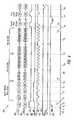
- Fig. 9 shows a timing diagram illustrating the timing of control, address, and data signals for a write operation performed by memory system 600 ( Fig. 6 ) wherein two sectors of information are simultaneously written in the non-volatile memory bank 506 ( Fig. 6 ) during a single write operation.
- the diagram includes: a wave form 902 representing a first flash signal which transmits time multiplexed command, address, and data information from flash state machine 642 ( Fig. 6 ) of the controller via bus 680 ( Fig. 6 ) to port 682 of the first flash memory chip; a wave form 904 representing a second flash signal which transmits time multiplexed command, address, and data signals from the flash state machine via bus 684 ( Fig. 6 ) to port 686 of the second flash memory chip; a time line 905; and a plurality of control signal wave forms.
- the control signal wave forms include: a wave form 906 representing a command line enable signal (CLE signal) transmitted from flash state machine 642 ( Fig. 6 ) to the first and second flash memory chips via control bus 690 ( Fig. 6 ); a wave form 908 representing an address line enable signal (ALE signal) transmitted from the flash state machine to the flash memory chips via the control bus; a wave form 910 representing a write enable signal (WE signal) transmitted from the flash state machine to the flash memory chips via the control bus; a wave form 912 representing a read enable signal (RE signal) transmitted from the flash state machine to the memory chips via the control bus; a wave form 914 representing a flash chip enable signal (FCE* signal) transmitted from chip enable signal output 700 ( Fig.
- a wave form 916 representing a flash ready/busy signal (FRDY-BSY* signal) transmitted from outputs 708 and 710 ( Fig. 6 ) of the first and second flash memory chips to the flash state machine via flash ready/busy signal line 706.
- the write operation commences at a time t0 at which the FCE* signal (wave form 914) transitions from a HIGH state to a LOW state thereby enabling the first and second flash memory chips to begin receiving command, address, data, and control signals.
- the FRDY_BSY* signal (wave form 916), transmitted from the flash memory chips to input 712 of the flash state machine ( Fig. 6 ), is already activated indicating that the first and second flash memory chips are ready to receive access commands.
- the CLE signal (wave form 906) is activated, transitioning from a LOW state to a HIGH state, thereby enabling the first and second flash memory chips to read command signals.
- the first and second flash signals (wave forms 902 and 904) simultaneously transmit a serial data shift-in command signal 80H to the first and second flash memory chips via the first and second first split buses 680 and 684 respectively.
- the WE signal (wave form 910) transitions from a HIGH state to a LOW state thereby enabling the first and second flash memory chips to read the serial data command signals 80H.
- the CLE signal (wave form 906) is deactivated, transitioning back to the LOW state, thereby disabling the flash memory chips from reading command signals.
- the ALE signal (wave form 908) is activated, transitioning from a LOW state to a HIGH state, thereby enabling the first and second flash memory chips to read packets of address information.
- the first and second flash signals (wave forms 902 and 904) each transmit first, second, and third address packets ADD0, ADD1, and ADD2 respectively to the first and second flash memory chips.
- the ALE signal (wave form 908) is deactivated, transitioning from the HIGH state to a LOW state, thereby disabling the first and second flash memory chips from reading address information.
- the WE signal transitions from a HIGH state to a LOW state thereby enabling the first and second flash memory chips to read the read the first, second, and third address packets ADD0, ADD1, and ADD2 respectively.
- the three address- packets ADD0, ADD1, and ADD2 specify a row-portion 732, 733 within a first sub-block 730 (Fig. 16).
- the first and second flash signals begin simultaneously transmitting interleaved even and odd data bytes wherein the even and odd bytes form one sector of information.
- the even bytes are transmitted to the first flash memory chip via bus 680 ( Fig. 6 ) and the odd sector bytes are transmitted to the second flash memory chip via bus 684 ( Fig. 6 ).
- the even data bytes D0, D2, D4,....D510 of the even sector are received by the first flash chip and stored in the first even sector field 734 (Fig. 16) of the corresponding location 732 of the first flash memory chip. This is done by storing a byte each time the write enable signal WE* (Wave form 910) is activated.
- the odd data bytes D1, D3, D5,....D511 of the even sector are received by the second flash chip and stored in the second even sector field 742 (Fig. 16) of the corresponding location 733 thereof with each byte being stored when the WE* signal is activated.
- the first and second flash signals (wave forms 902 and 904) complete transmission of the interleaved even and odd data bytes of the even sector.
- the first flash signal (wave form 902) transmits four packets of filler information (FFH, hexadecimal F, equivalent binary value "1111,” decimal value “15”) to the first flash memory chip via the first split bus 680 ( Fig. 6 ) while the second flash signal (wave form 904) transmits error correction codes (ECC) to the second flash memory chip via the second split bus 684 ( Fig. 6 ).
- the filler information FFH transmitted during this time period is received by the first flash memory chip and stored in the first spare field 736 (Fig. 16).
- the error correction code transmitted during this time period is received by the second flash memory chip and stored in the first error correction field 744 (Fig. 16) of the nonvolatile memory section 733 of the second flash memory chip.
- This error correction code generated by ECC logic unit 660 (Fig. 16), relates to the even sector transmitted during the preceding time interval between time t10 and t11.
- the first and second flash signals begin simultaneously transmitting interleaved even and odd data bytes, synchronous with the write enable signal WE* (wave form 910), of an odd sector to the first and second flash memory chips via the first and second first split buses 680 and 684 ( Fig. 6 ) respectively.
- the even data bytes D0, D2, D4,....D510 of the odd sector are received by the first flash chip and stored to the first odd sector field 738 (Fig. 16) of the corresponding location 732 of the first flash memory chip.
- the odd data bytes D1, D3, D5,....D511 of the odd sector are received by the second flash memory chip and stored to the second odd sector field 746 (Fig. 16) of the corresponding location 733 of the second flash memory chip.
- the first and second flash signals (wave forms 902 and 904) complete transmission of the interleaved even and odd data bytes of the odd sector.
- the first flash signal (wave form 902) transmits no information to the first flash memory chip thereby maintaining the value in corresponding storage location bytes of the first flash memory chip at FFH (hexadecimal) or all I's in binary.
- the second flash signal (wave form 904) transmits error correction codes (ECC) to the second flash memory chip via the second split bus 684 ( Fig. 6 ).
- ECC error correction codes
- the error correction code transmitted during this time period is received by the second flash memory chip and stored to the second error correction field 748 (Fig. 16) of the nonvolatile memory section 733 of the second flash memory chip.
- This error correction code generated by ECC logic unit 660 (Fig. 16), relates to the odd sector transmitted during the preceding time interval between time t11 and t12.
- the first and second flash signals each transmit a read command signal 70H to the first and second first and second flash memory chips via the first and second split buses 680 and 684 respectively.
- the WE signal transitions from a HIGH state to a LOW state thereby enabling the first and second flash memory chips to read the read command signals 70H.
- the CLE signal (wave form 906) is deactivated, transitioning back to the LOW state, thereby disabling the flash memory chips from reading command signals.
- the first and second flash signals each transmit a status command signal STATUS to the first and second first and second flash memory chips via the first and second split buses 680 and 684 respectively.
- the WE signal transitions from a HIGH state to a LOW state thereby enabling the first and second flash memory chips to read the read command signals 70H.
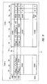
- Fig. 10 shows a table diagram generally illustrating the memory storage format, as depicted in Fig. 7 , for storing a block of information in memory bank 506 ( Fig. 6 ) wherein a single sector is written to a particular memory row location of the memory bank.
- a memory row location 728 designated ROW1 has an even sector S2 and an odd sector S3 stored therein in accordance with the format described above in reference to Fig. 7 .
- a memory row location 728 designated ROW2 has a single even sector S4 stored in the first and second even sector fields 734 and 742 of a corresponding pair of row-portions of the first and second flash memory chips 670, 672. Because no odd sector is required to be stored in this case, fields 736, 738, 746, 748, 750, and 752 are shown to be erased.
- Fig. 11 shows a table diagram illustrating the alternative memory storage format, as depicted in Fig. 7 , for storing a block of information in memory bank 506 ( Fig. 6 ) wherein a single sector is written to a particular memory row location of the memory bank.
- field 764 is a three bit field which is used for storing the old row flag in the first bit place, the used/free row flag in the second bit place, and the defect row flag in the third bit place.
- field 766 is a two bit field which is used for storing the even sector move flag in the first bit place and the odd sector move flag in the second bit place.
- a value of logic state "0" generally indicates that moved sectors have been updated by the host. Therefore, when the remaining sectors are moved from the old block which was not updated by the host, it can be determined that these sectors are not to be overwritten by the old data during the move.
- a memory location 728 designated ROW1 has an even sector S2 and an odd sector S3 stored therein in accordance with the format described above in reference to Fig. 7 .
- a memory location 728 designated ROW2 has a single even sector S4 stored in the first and second even sector fields 734 and 742 of a corresponding pair of row-portions of the first and second flash memory chips 670, 672. Because no odd sector is required to be stored in this case, fields 736, 738, 746, 748, 750, and 752 are shown to be erased.
- Fig. 12 is a flowchart illustrating a process of simultaneously writing two sectors of information to two memory units during a single write operation in accordance with the present invention.
- the memory controller 510 receives host addressing information from host 504 which specifies addresses for one or more sector locations, in the form of a logical block address (host-provided LBA) or in the form of cylinder head sector (CHS) information. If the host addressing information is in the form of CHS information, the controller translates the CHS information to LBA information. As mentioned, the sectors are organized in blocks and therefore, the host-provided LBA's may correspond to sectors of more than one block. This information is used by microprocessor 620 ( Fig. 6 ) as will be further discussed below.
- host-provided LBA logical block address
- CHS cylinder head sector
- Microprocessor 620 executes instructions, which are stored in code storage unit 626 ( Fig. 6 ) to carry out the depicted process.
- a sector count value is set equal to the number of sector locations of a current block, being addressed by the host wherein a sector location may, for example, be comprised of fields 734 and 742 ( Fig. 7 ) or fields 738 and 746 ( Fig. 7 ) of the memory bank.
- the microprocessor determines at 1206 whether or not each of the sector locations specified by the host-provided LBA values has been accessed by the host before. This determination is made by reading the contents of the corresponding virtual PBA field 804 ( Fig.
- step 1210 If it is determined that one or more sector locations, of the current block, specified by the host-provided-LBA's have been accessed previously by the host, the write process proceeds to step 1210 in which microprocessor 620 ( Fig. 6 ) sets the corresponding one of the move flags 760, 762 ( Fig. 7 ) corresponding to the current sector location, and the write process proceeds to step 1208.
- microprocessor 620 Fig. 6
- the microprocessor maintains the status of sectors as to whether or not they have been moved to other blocks. This is done by keeping track of two values for each block.
- One value is the starting sector location within a block where sectors have been moved and the second value is the number sectors within the block that have been moved. With these two values, status information as to whether or not and which sectors of a block have been moved to other block(s) may be reconstructed.
- step 1206 If it is determined, at step 1206, that none of the sector locations of the current block specified by the host-provided-LBA have been previously accessed, the write process proceeds directly to step 1208.
- step 1208 the space manager 636 ( Fig. 6 ) of the controller searches for a free (or unused) block, such as block 727 ( Fig. 7 ) located within the nonvolatile memory bank, each free block being identified by a specific virtual PBA value.
- the microprocessor determines at 1212 whether a free block is located, and if not, an error is reported by the controller 510 ( Fig. 6 ) to the host indicating that the nonvolatile memory bank is unable to accommodate further storage of information. As this can result in a fatal system error, the inventors of the present invention have exercised great care in preventing this situation from occurring.
- step 1214 microprocessor 620 prompts space manager 636 ( Fig. 6 ) to assign a virtual PBA value 822 ( Fig. 8B ) to the free block found in step 1208.
- This virtual PBA value is stored in the LBA-PBA map 800 ( Fig. 8A ) in a map row location 802 ( Fig. 8A ) identified by the masked bits 814 ( Fig. 8B ) of the host-provided LBA corresponding to the current block.
- the masked bits 814 Fig.
- the microprocessor determines whether the actual PBA value is an even or odd value.
- the host-provided LBA may be checked in place of the actual PBA value to determine whether this value is odd or even.
- each sector includes 512 bytes of user data and 16 bytes of overhead information.
- the microprocessor waits until such a transfer is completed, as shown by the 'NO' branch loop at 1232.
- the microprocessor initiates the writing of the two sectors that have been temporarily saved to the data buffer to the memory bank 506 ( Fig. 6 ) by issuing a write command, followed by address and data information.
- the write operation at step 1234 is performed according to the method and apparatus discussed above relative to Figs. 7 and 9 .
- step 1235 Upon completion of writing two sectors of information, the write operation is verified at 1235. If information was not correctly programmed into the sectors at step 1234, the process continues to step 1237 where a defect management routine is performed, as will be discussed in greater detail below. After execution of the defect management routine, the sector count is decremented by two at step 1236. At 1235, if the write operation was verified as being successful, step 1236 is executed and no defect management is necessary. The microprocessor then determines at 1238 whether the sector count is equal to zero and if so, it is assumed that no more sectors remain to be written and the process proceeds to 1228. If, however, more sectors need to be written the process proceeds to step 1240 at which the host-provided LBA is incremented by two to point to the next sector that is to be written.
- the microprocessor determines whether the last sector of the block has been reached.
- the block boundary is determined by comparing the 'offset' value of the current LBA to the number of sectors in a block, and if those values are equal, a block boundary is reached. For example, in the preferred embodiment, since a block includes 32 sectors, the 'offset' value of the current LBA is compared against '32' (in decimal notation). If alternatively, a block is defined to have other than 32 sectors, such as 16 sectors, the latter is compared against the 'offset'.
- step 1206 the virtual PBA value corresponding to the current LBA value is checked for an all 'I's condition and so on. If a block boundary is not reached at step 1242, the write process continues from step 1218.
- the microprocessor proceeds to determine at 1220 whether data buffer 614 ( Fig. 6 ) has received at least one sector of information from the host. If not, the microprocessor waits until one sector of information is transferred from the host to the data buffer 614. Upon receipt of one sector of information, writing of the next sector is initiated and performed at step 1222 according to the method and apparatus discussed above relative to Figs. 10 and 11 . Upon completion of writing a sector of information, the write operation is verified at 1223. If information was not correctly programmed into the sector at step 1222, the process continues to step 1225 where a defect management routine is performed, as will be discussed in greater detail below.
- step 1224 the sector count is decremented by one. If at 1223, it is determined that the write operation was correctly performed, the process continues to step 1224 and no defect management routine is executed.
- the microprocessor determines whether the sector count is equal to zero and, if not, the host-provided LBA is incremented by one and the write process continues to step 1242 where the microprocessor checks for a block boundary as explained above.
- step 1226 If at step 1226, as in step 1238, it is determined that no more sectors remain to be written, i.e. the sector count is zero, the depicted process proceeds to 1228 at which the microprocessor determines whether the move flag is set. As noted above, the move flag would be set at step 1210 if it was determined at 1206 that an LBA was being re-accessed by the host.
- the write process ends. However, upon a determined at 1228 that the move flag is set, the block is updated. That is, those sectors of the current block that were not accessed are moved to corresponding sector locations in the block within memory bank 506 identified by the virtual PBA value assigned in step 1214 to the free block found in step 1208. This is perhaps best understood by an example.
- step 1230 after the sectors, identified by host-provided LBAs 3, 4, and 5, have been written to corresponding sectors of the block identified by virtual PBA "8", sectors in the block identified by virtual PBA "3" that were not re-accessed during the write operation are moved from the block identified by virtual PBA "3" to corresponding sector locations of the block identified by virtual PBA "8” and the block identified by virtual PBA "3” is thereafter erased.
- This example assumes that remaining sectors of the block identified by virtual PBA "3”, such as sectors 0 and 7-31 (assuming there are 32 sectors in a block), were not accessed since the last erase of the block in which they reside and therefore contain no valid sector information. Otherwise, if those sectors were previously accessed, then they would also be moved to the virtual PBA location 8.
- Step 1230 may be implemented in many ways.
- the inventors of the present invention disclose various methods and apparatus which may be alternatively employed for performing the move operation of step 1230.
- Serial No. 08/946,331 entitled “Moving Sequential Sectors Within a Block of Information In a Flash Memory Mass Storage Architecture", filed on Oct. 7, 1997
- Serial No. 08/831,266 entitled “Moving Sectors Within a Block of Information In a Flash Memory Mass Storage Architecture"
- the disclosures of which are herein incorporated by reference are herein incorporated by reference.
- Fig. 12a shows the steps performed by the micorprocessor if the defect management routine at steps 1237 and 1225 (in Fig. 12 ) is executed.
- the block management routine is executed when the write operation is not successfully verified; the block(s) being programmed is in some way defective and a different area in the nonvolatile memory, i.e. another block need be located for programming therein.
- the block that was being unsuccessfully programmed is marked as "defective” by setting the "defect" flags 756 (in Fig. 7 ).
- the space manager within the controller is commanded to find a free block.
- the information that would have been programmed at steps 1234 and 1222 (in Fig. 12 ) i.e. the block marked "defective" is programmed into corresponding sector locations within the free block found in step 1602.
- step 1606 the block marked "defective" is checked for the presence of any sector information that was previously written thereto successfully. If any such sectors exist, at step 1608, these previouly-programmed sectors are moved to the free block, as is additional block information in the process of Fig. 12 .
- Fig. 13 shows a table diagram generally illustrating a memory storage format for storing a block, including 32 sectors, of information in memory bank 506 in accordance with an alternative embodiment of the present invention.
- memory bank 506 includes a plurality of M blocks 1302 designated BLCK0, BLCK1, BLCK(M-1) each having a physical block addresses (PBA).
- Each block 1302 of memory bank 506 is comprised of a first sub-block 1306 of first flash memory chip 670, and a corresponding second sub-block 1308 of second flash memory chip 672 wherein the corresponding sub-blocks are identified by the same virtual PBA.
- Each memory row location 1304 includes a first row-portion 1310 and a corresponding second row-portion 1312.
- each of the first and second row-portions 1310, 1312 includes storage for 512 bytes of data information plus additional storage space for error correction information (ECC information) and flag information.
- ECC information error correction information
- Each of the first row-portions 1310 includes an even sector field 1314 for storing an even sector (S0, S2, S4,...) of information, and an even sector error correction field 1316 for storing error correction information corresponding to the even sector stored in field 1314.
- Each of the second row-portions 1312 includes an odd sector field 1318 for storing an odd sector (S1, S3, S5,%) of information, an odd sector error correction field 1320 for storing error correction information corresponding to the odd sector stored in 1318, a block address field 1322, and a flag field 1324. It is understood in the present invention that field 1314 could alternatively be used to store an odd sector while field 1318 could alternatively be used to store an even sector. Also, first row-portion 1310 could alternatively be used for storing the block address and flags.
- Flag field 1324 is used for storing flag information which is used by controller 510 ( Fig. 6 ) during access operations as further explained below.
- Block address field 1322 is used for storing the block address permanently assigned to block 1302, such as "0" for BLCK0. Only a single block address entry is required in the block address field per block. In a preferred embodiment, a block address entry is entered in block address field 1322 of the last row 1304, which is row 15.
- the first and second split buses 680, 684 include lines coupled to receive data bytes of the even and odd sectors respectively.
- the controller 510 ( Fig. 6 ) writes two sectors simultaneously by simultaneously writing a byte of an even sector and an odd sector simultaneously via the first and second split buses 680, 684 ( Fig. 6 ), respectively.
- the split buses 680, 684 ( Fig. 6 ) also provide for: transmission of ECC information between the flash memory chips and the flash state machine 642 and ECC logic unit 660 of the memory controller 510; and transmission of address information from flash state machine 642 to the flash memory chips.
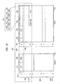
- Fig. 14 shows a timing diagram illustrating the timing of control signals, address signals, and data signals for an erase operation of the memory system of Fig. 6 .
- the diagram includes: the wave form 902 representing the first flash signal which transmits time multiplexed command, address, and data information from the flash state machine 642 ( Fig. 6 ) via first split bus 680 ( Fig. 6 ) to the first flash memory chip; the wave form 904 representing the second flash signal which transmits time multiplexed command, address, and data signals transmitted from the flash state machine via second split bus 684 ( Fig. 6 ) to the second flash memory chip; a time line 1450; and a plurality of control signal wave forms.
- control signal wave forms include: wave form 906 representing the command line enable (CLE) signal; wave form 908 representing the address line enable (ALE) signal; wave form 910 representing the write enable (WE) signal; wave form 912 representing the read enable (RE) signal; wave form 914 representing the flash chip enable (FCE*) signal; and wave form 916 representing the flash ready/busy signal (FRDY_BSY* signal).
- the erase operation commences at a time E0 at which the FCE* signal (wave form 914) transitions from a HIGH state to a LOW state thereby enabling the first and second flash memory chips to begin receiving command, address, and data signals.
- the CLE signal (wave form 906) is activated, transitioning from a LOW state to a HIGH state, thereby enabling the first and second flash memory chips to read command signals.
- the first and second flash signals (wave forms 902 and 904) each transmit a command signal.
- the first flash signal (wave form 902) transmits an 'erase set' command, 60H, via the first split bus 680 ( Fig.
- the second flash signal (wave form 904) transmits a read status command signal 70H via the second split bus 684 ( Fig. 6 ) to the second flash memory chip.
- the WE signal (wave form 910) transitions from a HIGH state to a LOW state thereby enabling the first and second flash memory chips to read the command signals 60H and 70H.
- the CLE signal (wave form 906) is deactivated, transitioning back to the LOW state, thereby disabling the flash memory chips from reading command signals.
- the ALE signal (wave form 908) is activated, transitioning from a LOW state to a HIGH state, thereby enabling the first and second flash memory chips to read packets of address information.
- the first flash signal (wave form 902) transmits first and second address packets ADD0 and ADD1 respectively to the first flash memory chip wherein the first and second address packets ADD0 and ADD1 specify a sub-block 730 ( Fig. 7 ) of the first flash memory chip 670 of the memory bank.
- the ALE signal (wave form 908) is deactivated.
- the WE signal (wave form 910) transitions to the LOW state to enable the flash memory chip to read the address packets.
- the CLE signal (wave form 906) is again activated to enable the first and second memory chips to read command signals.
- the first flash signal (wave form 902) transmits DOH, which is an 'erase confirm command' to the first flash memory chip. This command, as sampled by the CLE signal, actually initiates the erase operation within the flash chips, after which, the contents of data fields 734 and 738 of each memory row portion 732 of the addressed sub-block 730 ( Fig. 7 ) of the first flash memory chip 670 are erased, i.e. set to an "all I's" state.
- the FRDY-BSY* signal (wave form 912) transitions from a HIGH state to a LOW state to indicate to the flash state machine 642 ( Fig. 6 ) that at least one of the flash memory chips is busy.
- the CLE signal (wave form 906) is activated to enable the first and second flash memory chips to read command signals.
- the first and second flash signals (wave forms 902 and 904) each transmit a command signal.
- the first flash signal (wave form 902) transmits a read command signal 70H via the first split bus 680 ( Fig. 6 ) to the first flash memory chip while the second flash signal (wave form 904) transmits an erase command signal 60H via the second split bus 684 ( Fig. 6 ) to the second flash memory chip.
- the WE signal (wave form 910) transitions to the LOW state to enable the first and second flash memory chips to read the command signals 60H and 70H.
- the CLE signal (wave form 906) is deactivated to disable the flash memory chips from reading command signals and the ALE signal (wave form 908) is activated thereby enabling the first and second flash memory chips to read packets of address information.
- the second flash signal (wave form 904) transmits first and second address packets ADD0 and ADD1 respectively to the second flash memory chip wherein the first and second address packets ADD0 and ADD1 specify a sub-block 731 ( Fig. 7 ) of the second flash memory chip 672 of the memory bank.
- the ALE signal (wave form 908) is deactivated.
- the WE signal (wave form 910) enables the flash memory chips to read the address packets.
- the CLE signal (wave form 906) is again activated to enable the first and second memory chips to read command signals.
- the first flash signal (wave form 902) transmits DOH to the first flash memory chip to erase the contents of data fields 734 and 738 of each memory row portion 732 of the specified block and thereby set them to an "all 1's" state.
- the memory controller erases an addressed sub-block 730 ( Fig. 7 ) of the first flash memory chip 670. Also, during a time interval TEB2, between the times E11 and E20, the memory controller erases a corresponding addressed sub-block 731 ( Fig. 7 ) of the second flash memory chip 672.
- the FRDY_BSY* signal transitions from a LOW state to a HIGH state to indicate to the flash state machine 642 ( Fig. 6 ) that both of the flash memory chips are finished with the erase operation.
- the first and second flash signals (wave forms 902 and 904) each transmit a read status command signal 70H to the first and second flash memory chips respectively. While the read command signals 70H are active, the WE signal (wave form 910) transitions to the LOW state thereby enabling the first and second flash memory chips to read the read command signals 70H.
- the first and second flash signals (wave forms 902 and 904) both transmit a status data back to the controller.
- the entire block 727 ( Fig. 7 ) within the chips is marked defective by setting the contents of the defect flag 756 ( Fig. 7 ) in the second flash memory chip 672.
- Fig. 15 is a flowchart illustrating a process of erasing a block, including a first sub-block stored in a first memory unit and a second sub-block stored in a second memory unit, in accordance with the present invention.
- Microprocessor 620 executes instructions, which are stored in code RAM 626 ( Fig. 6 ) to carry out the depicted process.
- microprocessor 620 ( Fig. 6 ) loads a block address to be erased.
- the microprocessor initiates the erase operations described above in reference to the timing diagram at 1400 ( Fig. 14 ).
- the microprocessor determines whether the erase operation is finished by reading the flash ready/busy (FRDY_BSY* ) signal (wave form 916 of Fig. 14 ) which transitions from a LOW state to a HIGH state to indicate to the flash state machine 642 ( Fig. 6 ) that both of the flash memory chips are finished with the erase operation.
- the microprocessor reads the status of the flash chips 670, 672 ( Fig. 6 ).
- the microprocessor determines whether the erase operation performed in step 1504 was successful in both of the flash chips 670, 672 ( Fig. 6 ) and, if so, the process ends. If it is determined that the erase operation performed in step 1504 was not successful in both of the flash chips, then the microprocessor marks the block in both of the flash chips 670, 672 defective.
Landscapes
- Engineering & Computer Science (AREA)
- Theoretical Computer Science (AREA)
- Physics & Mathematics (AREA)
- General Engineering & Computer Science (AREA)
- General Physics & Mathematics (AREA)
- Human Computer Interaction (AREA)
- Techniques For Improving Reliability Of Storages (AREA)
- Memory System (AREA)
- Information Retrieval, Db Structures And Fs Structures Therefor (AREA)
- Read Only Memory (AREA)
Applications Claiming Priority (3)
| Application Number | Priority Date | Filing Date | Title |
|---|---|---|---|
| US09/030,697 US6081878A (en) | 1997-03-31 | 1998-02-25 | Increasing the memory performance of flash memory devices by writing sectors simultaneously to multiple flash memory devices |
| PCT/US1999/004247 WO1999044113A2 (en) | 1998-02-25 | 1999-02-25 | Increasing the memory performance of flash memory devices by writing sectors simultaneously to multiple flash memory devices |
| EP99911004A EP0983550A4 (de) | 1998-02-25 | 1999-02-25 | Leistungsverbesserung in flash-speichern durch gleichzeitige schreiboperation in mehreren vorrichtungen |
Related Parent Applications (2)
| Application Number | Title | Priority Date | Filing Date |
|---|---|---|---|
| EP99911004A Division EP0983550A4 (de) | 1998-02-25 | 1999-02-25 | Leistungsverbesserung in flash-speichern durch gleichzeitige schreiboperation in mehreren vorrichtungen |
| EP99911004.2 Division | 1999-02-25 |
Publications (2)
| Publication Number | Publication Date |
|---|---|
| EP2306321A1 true EP2306321A1 (de) | 2011-04-06 |
| EP2306321B1 EP2306321B1 (de) | 2018-08-08 |
Family
ID=21855540
Family Applications (2)
| Application Number | Title | Priority Date | Filing Date |
|---|---|---|---|
| EP99911004A Withdrawn EP0983550A4 (de) | 1998-02-25 | 1999-02-25 | Leistungsverbesserung in flash-speichern durch gleichzeitige schreiboperation in mehreren vorrichtungen |
| EP10012048.4A Expired - Lifetime EP2306321B1 (de) | 1998-02-25 | 1999-02-25 | Erhöhung der Speicherleistung in Flash-Speichervorrichtungen mittels gleichzeitiger Durchführung des Schreibvorgangs auf mehreren Vorrichtungen |
Family Applications Before (1)
| Application Number | Title | Priority Date | Filing Date |
|---|---|---|---|
| EP99911004A Withdrawn EP0983550A4 (de) | 1998-02-25 | 1999-02-25 | Leistungsverbesserung in flash-speichern durch gleichzeitige schreiboperation in mehreren vorrichtungen |
Country Status (5)
| Country | Link |
|---|---|
| US (4) | US6081878A (de) |
| EP (2) | EP0983550A4 (de) |
| JP (6) | JP3792259B2 (de) |
| AU (1) | AU2975099A (de) |
| WO (1) | WO1999044113A2 (de) |
Families Citing this family (256)
| Publication number | Priority date | Publication date | Assignee | Title |
|---|---|---|---|---|
| US5430859A (en) | 1991-07-26 | 1995-07-04 | Sundisk Corporation | Solid state memory system including plural memory chips and a serialized bus |
| US8171203B2 (en) | 1995-07-31 | 2012-05-01 | Micron Technology, Inc. | Faster write operations to nonvolatile memory using FSInfo sector manipulation |
| US6978342B1 (en) | 1995-07-31 | 2005-12-20 | Lexar Media, Inc. | Moving sectors within a block of information in a flash memory mass storage architecture |
| US5845313A (en) | 1995-07-31 | 1998-12-01 | Lexar | Direct logical block addressing flash memory mass storage architecture |
| US6728851B1 (en) | 1995-07-31 | 2004-04-27 | Lexar Media, Inc. | Increasing the memory performance of flash memory devices by writing sectors simultaneously to multiple flash memory devices |
| US5890192A (en) * | 1996-11-05 | 1999-03-30 | Sandisk Corporation | Concurrent write of multiple chunks of data into multiple subarrays of flash EEPROM |
| JPH10326493A (ja) * | 1997-05-23 | 1998-12-08 | Ricoh Co Ltd | 複合化フラッシュメモリ装置 |
| JPH117505A (ja) * | 1997-06-17 | 1999-01-12 | Fujitsu Ltd | カード型記憶媒体 |
| JP4079506B2 (ja) * | 1997-08-08 | 2008-04-23 | 株式会社東芝 | 不揮発性半導体メモリシステムの制御方法 |
| US6182162B1 (en) | 1998-03-02 | 2001-01-30 | Lexar Media, Inc. | Externally coupled compact flash memory card that configures itself one of a plurality of appropriate operating protocol modes of a host computer |
| GB2339044B (en) * | 1998-03-02 | 2003-06-04 | Lexar Media Inc | Flash memory card with enhanced operating mode detection and user-friendly interfacing system |
| US7047357B1 (en) * | 1998-10-01 | 2006-05-16 | Intel Corporation | Virtualized striping controller |
| US6901457B1 (en) | 1998-11-04 | 2005-05-31 | Sandisk Corporation | Multiple mode communications system |
| GB9903490D0 (en) | 1999-02-17 | 1999-04-07 | Memory Corp Plc | Memory system |
| US6427186B1 (en) * | 1999-03-30 | 2002-07-30 | Frank (Fong-Long) Lin | Memory, interface system and method for mapping logical block numbers to physical sector numbers in a flash memory, using a master index table and a table of physical sector numbers |
| US6141249A (en) * | 1999-04-01 | 2000-10-31 | Lexar Media, Inc. | Organization of blocks within a nonvolatile memory unit to effectively decrease sector write operation time |
| US6401161B1 (en) | 1999-04-15 | 2002-06-04 | Dell Products, Lp | High speed bus interface for non-volatile integrated circuit memory supporting continuous transfer |
| US6467015B1 (en) * | 1999-04-15 | 2002-10-15 | Dell Products, L.P. | High speed bus interface for non-volatile integrated circuit memory supporting continuous transfer |
| US6622199B1 (en) * | 1999-07-02 | 2003-09-16 | Qualcomm Incorporated | Method for minimizing data relocation overhead in flash based file systems |
| CN1227591C (zh) * | 1999-07-28 | 2005-11-16 | 索尼公司 | 记录系统、数据记录设备、存储设备和数据记录方法 |
| US7744387B2 (en) * | 1999-08-04 | 2010-06-29 | Super Talent Electronics, Inc. | Multi-level cell (MLC) rotate flash memory device |
| US7984303B1 (en) | 2000-01-06 | 2011-07-19 | Super Talent Electronics, Inc. | Flash memory devices with security features |
| US20080071973A1 (en) * | 2000-01-06 | 2008-03-20 | Chow David Q | Electronic data flash card with various flash memory cells |
| US7702831B2 (en) * | 2000-01-06 | 2010-04-20 | Super Talent Electronics, Inc. | Flash memory controller for electronic data flash card |
| US8043099B1 (en) | 2004-02-12 | 2011-10-25 | Super Talent Electronics, Inc. | Extended USB plug, USB PCBA, and USB flash drive with dual-personality |
| US8102662B2 (en) * | 2007-07-05 | 2012-01-24 | Super Talent Electronics, Inc. | USB package with bistable sliding mechanism |
| US7628622B2 (en) * | 1999-08-04 | 2009-12-08 | Super Talent Electronics, Inc. | Multi-level cell (MLC) slide flash memory |
| US8625270B2 (en) | 1999-08-04 | 2014-01-07 | Super Talent Technology, Corp. | USB flash drive with deploying and retracting functionalities using retractable cover/cap |
| US8073985B1 (en) | 2004-02-12 | 2011-12-06 | Super Talent Electronics, Inc. | Backward compatible extended USB plug and receptacle with dual personality |
| US8078794B2 (en) * | 2000-01-06 | 2011-12-13 | Super Talent Electronics, Inc. | Hybrid SSD using a combination of SLC and MLC flash memory arrays |
| US7690031B2 (en) * | 2000-01-06 | 2010-03-30 | Super Talent Electronics, Inc. | Managing bad blocks in flash memory for electronic data flash card |
| US8240034B1 (en) | 2000-01-06 | 2012-08-14 | Super Talent Electronics, Inc. | High throughput manufacturing method for micro flash memory cards |
| US7676640B2 (en) * | 2000-01-06 | 2010-03-09 | Super Talent Electronics, Inc. | Flash memory controller controlling various flash memory cells |
| US7788553B2 (en) * | 2000-01-06 | 2010-08-31 | Super Talent Electronics, Inc. | Mass production testing of USB flash cards with various flash memory cells |
| US20080082813A1 (en) * | 2000-01-06 | 2008-04-03 | Chow David Q | Portable usb device that boots a computer as a server with security measure |
| US20050204187A1 (en) * | 2004-03-11 | 2005-09-15 | Lee Charles C. | System and method for managing blocks in flash memory |
| US7440287B1 (en) | 2000-01-06 | 2008-10-21 | Super Talent Electronics, Inc. | Extended USB PCBA and device with dual personality |
| US7874067B1 (en) | 2000-01-06 | 2011-01-25 | Super Talent Electronics, Inc. | Manufacturing method for single chip COB USB devices with optional embedded LED |
| US6381175B2 (en) * | 2000-01-10 | 2002-04-30 | Texas Instruments Incorporated | Method and system for validating flash memory |
| US7102671B1 (en) | 2000-02-08 | 2006-09-05 | Lexar Media, Inc. | Enhanced compact flash memory card |
| US6426893B1 (en) | 2000-02-17 | 2002-07-30 | Sandisk Corporation | Flash eeprom system with simultaneous multiple data sector programming and storage of physical block characteristics in other designated blocks |
| US6467014B1 (en) * | 2000-02-29 | 2002-10-15 | Plasmon Lms, Inc. | Automatic mapping and efficient address translation for multi-surface, multi-zone storage devices |
| US6851026B1 (en) | 2000-07-28 | 2005-02-01 | Micron Technology, Inc. | Synchronous flash memory with concurrent write and read operation |
| US6675278B1 (en) * | 2000-04-19 | 2004-01-06 | Motorola, Inc. | Method and apparatus for managing memory |
| US6772273B1 (en) | 2000-06-29 | 2004-08-03 | Intel Corporation | Block-level read while write method and apparatus |
| US6721843B1 (en) * | 2000-07-07 | 2004-04-13 | Lexar Media, Inc. | Flash memory architecture implementing simultaneously programmable multiple flash memory banks that are host compatible |
| US7167944B1 (en) | 2000-07-21 | 2007-01-23 | Lexar Media, Inc. | Block management for mass storage |
| US7155559B1 (en) | 2000-08-25 | 2006-12-26 | Lexar Media, Inc. | Flash memory architecture with separate storage of overhead and user data |
| US6772274B1 (en) * | 2000-09-13 | 2004-08-03 | Lexar Media, Inc. | Flash memory system and method implementing LBA to PBA correlation within flash memory array |
| US7020739B2 (en) * | 2000-12-06 | 2006-03-28 | Tdk Corporation | Memory controller, flash memory system having memory controller and method for controlling flash memory device |
| DE10064356A1 (de) * | 2000-12-21 | 2002-07-11 | Claas Selbstfahr Erntemasch | Vorrichtung und Verfahren zur Erntegutförderung in landwirtschaftlichen Arbeitsmaschinen |
| DE10064649A1 (de) * | 2000-12-22 | 2002-07-04 | Bosch Gmbh Robert | Schnittstelle für einen Speicher und Verfahren zum variablen Konfigurieren einer Speichervorrichtung |
| TW539950B (en) * | 2000-12-28 | 2003-07-01 | Sony Corp | Data recording device and data write method for flash memory |
| US6763424B2 (en) * | 2001-01-19 | 2004-07-13 | Sandisk Corporation | Partial block data programming and reading operations in a non-volatile memory |
| JP4711531B2 (ja) * | 2001-03-23 | 2011-06-29 | ルネサスエレクトロニクス株式会社 | 半導体記憶装置 |
| US6754765B1 (en) * | 2001-05-14 | 2004-06-22 | Integrated Memory Logic, Inc. | Flash memory controller with updateable microcode |
| JP4256600B2 (ja) * | 2001-06-19 | 2009-04-22 | Tdk株式会社 | メモリコントローラ、メモリコントローラを備えるフラッシュメモリシステム及びフラッシュメモリの制御方法 |
| US6603683B2 (en) * | 2001-06-25 | 2003-08-05 | International Business Machines Corporation | Decoding scheme for a stacked bank architecture |
| JP4059473B2 (ja) * | 2001-08-09 | 2008-03-12 | 株式会社ルネサステクノロジ | メモリカード及びメモリコントローラ |
| JP2003067244A (ja) | 2001-08-24 | 2003-03-07 | Matsushita Electric Ind Co Ltd | 不揮発性記憶装置及びその制御方法 |
| GB0123410D0 (en) * | 2001-09-28 | 2001-11-21 | Memquest Ltd | Memory system for data storage and retrieval |
| GB0123416D0 (en) | 2001-09-28 | 2001-11-21 | Memquest Ltd | Non-volatile memory control |
| GB0123412D0 (en) * | 2001-09-28 | 2001-11-21 | Memquest Ltd | Memory system sectors |
| GB0123421D0 (en) * | 2001-09-28 | 2001-11-21 | Memquest Ltd | Power management system |
| GB0123415D0 (en) | 2001-09-28 | 2001-11-21 | Memquest Ltd | Method of writing data to non-volatile memory |
| GB0123417D0 (en) * | 2001-09-28 | 2001-11-21 | Memquest Ltd | Improved data processing |
| GB0123419D0 (en) | 2001-09-28 | 2001-11-21 | Memquest Ltd | Data handling system |
| EP1308964B1 (de) * | 2001-10-25 | 2007-10-03 | STMicroelectronics S.r.l. | Schnelle Programmiermethode für nichtflüchtige Speicher, insbesondere flash Speicher und ähnliche Speicherarchitekturen |
| US6976143B2 (en) | 2001-11-13 | 2005-12-13 | Hewlett-Packard Development Company, L.P. | Systems and methods for controlling communication with nonvolatile memory devices |
| US6721229B1 (en) * | 2001-12-19 | 2004-04-13 | Network Equipment Technologies, Inc. | Method and apparatus for using SDRAM to read and write data without latency |
| JP4061272B2 (ja) * | 2002-01-09 | 2008-03-12 | 株式会社ルネサステクノロジ | メモリシステム及びメモリカード |
| TWI240861B (en) * | 2002-01-11 | 2005-10-01 | Integrated Circuit Solution In | Data access method and architecture of flash memory |
| US6621739B2 (en) | 2002-01-18 | 2003-09-16 | Sandisk Corporation | Reducing the effects of noise in non-volatile memories through multiple reads |
| US6957295B1 (en) | 2002-01-18 | 2005-10-18 | Lexar Media, Inc. | File management of one-time-programmable nonvolatile memory devices |
| US6950918B1 (en) | 2002-01-18 | 2005-09-27 | Lexar Media, Inc. | File management of one-time-programmable nonvolatile memory devices |
| CN100533378C (zh) * | 2002-01-31 | 2009-08-26 | 松下电器产业株式会社 | 信息处理装置和方法、存储器管理装置和方法 |
| US6839826B2 (en) | 2002-02-06 | 2005-01-04 | Sandisk Corporation | Memory device with pointer structure to map logical to physical addresses |
| US20030156207A1 (en) * | 2002-02-20 | 2003-08-21 | Creo Il. Ltd | Image capture apparatus with backup memory |
| JP2005518589A (ja) * | 2002-02-22 | 2005-06-23 | レクサー メディア,インク. | インジケータライトが一体化されたリムーバブル記憶媒体 |
| US7231643B1 (en) | 2002-02-22 | 2007-06-12 | Lexar Media, Inc. | Image rescue system including direct communication between an application program and a device driver |
| US6871257B2 (en) | 2002-02-22 | 2005-03-22 | Sandisk Corporation | Pipelined parallel programming operation in a non-volatile memory system |
| US7242632B2 (en) | 2002-06-20 | 2007-07-10 | Tokyo Electron Device Limited | Memory device, memory managing method and program |
| US6941411B2 (en) * | 2002-08-21 | 2005-09-06 | Micron Technology, Inc. | Non-contiguous address erasable blocks and command in flash memory |
| US20040054846A1 (en) * | 2002-09-16 | 2004-03-18 | Wen-Tsung Liu | Backup device with flash memory drive embedded |
| JP4129381B2 (ja) * | 2002-09-25 | 2008-08-06 | 株式会社ルネサステクノロジ | 不揮発性半導体記憶装置 |
| DE10256502A1 (de) * | 2002-12-04 | 2004-06-24 | Hyperstone Ag | Speichersystem mit mehreren Speichercontrollern und Verfahren zu deren Synchronisierung |
| US6944063B2 (en) * | 2003-01-28 | 2005-09-13 | Sandisk Corporation | Non-volatile semiconductor memory with large erase blocks storing cycle counts |
| TWI220474B (en) * | 2003-03-12 | 2004-08-21 | Glovic Electronics Corp | Physical page allocation method of flash memory |
| US6900761B2 (en) * | 2003-04-03 | 2005-05-31 | Optistreams, Inc. | Automated portable remote robotic transceiver with directional antenna |
| US6973519B1 (en) | 2003-06-03 | 2005-12-06 | Lexar Media, Inc. | Card identification compatibility |
| US6906961B2 (en) * | 2003-06-24 | 2005-06-14 | Micron Technology, Inc. | Erase block data splitting |
| US7426596B2 (en) * | 2003-07-30 | 2008-09-16 | Hewlett-Packard Development Company, L.P. | Integrated circuit with a scalable high-bandwidth architecture |
| US7343440B2 (en) * | 2003-07-30 | 2008-03-11 | Hewlett-Packard Development Company, L.P. | Integrated circuit with a scalable high-bandwidth architecture |
| US7771215B1 (en) | 2003-12-02 | 2010-08-10 | Super Talent Electronics, Inc. | MLC COB USB flash memory device with sliding plug connector |
| WO2005059854A2 (en) | 2003-12-17 | 2005-06-30 | Lexar Media, Inc. | Electronic equipment point-of-sale activation to avoid theft |
| CN100433195C (zh) * | 2003-12-31 | 2008-11-12 | 深圳市朗科科技股份有限公司 | 闪存介质数据写入方法 |
| TW200523946A (en) * | 2004-01-13 | 2005-07-16 | Ali Corp | Method for accessing a nonvolatile memory |
| US8021166B1 (en) | 2004-02-12 | 2011-09-20 | Super Talent Electronics, Inc. | Extended USB plug, USB PCBA, and USB flash drive with dual-personality for embedded application with mother boards |
| RU2325689C2 (ru) * | 2004-01-20 | 2008-05-27 | ТРЕК 2000 Интернейшнл Лтд. | Портативное устройство хранения данных с использованием множества запоминающих устройств |
| US7815469B1 (en) | 2004-02-12 | 2010-10-19 | Super Talent Electronics, Inc. | Dual-personality extended USB plugs and receptacles using with PCBA and cable assembly |
| US7869219B2 (en) * | 2004-01-20 | 2011-01-11 | Super Talent Electronics, Inc. | Flash drive with spring-loaded retractable connector |
| WO2005069150A1 (en) * | 2004-01-20 | 2005-07-28 | Trek 2000 International Ltd. | Portable data storage device using multiple memory devices |
| US8014130B1 (en) | 2004-02-26 | 2011-09-06 | Super Talent Electronics, Inc. | Pen-like universal serial bus (USB) flash drive with deploying and retracting functionalities |
| KR100608592B1 (ko) | 2004-01-27 | 2006-08-03 | 삼성전자주식회사 | 플래시 메모리의 데이터 관리 장치 및 방법 |
| US7607177B2 (en) * | 2004-02-23 | 2009-10-20 | Micron Technology, Inc. | Secure compact flash |
| US20080147964A1 (en) * | 2004-02-26 | 2008-06-19 | Chow David Q | Using various flash memory cells to build usb data flash cards with multiple partitions and autorun function |
| US7806705B2 (en) * | 2004-02-26 | 2010-10-05 | Super Talent Electronics, Inc. | Slide flash memory devices |
| US20080082736A1 (en) * | 2004-03-11 | 2008-04-03 | Chow David Q | Managing bad blocks in various flash memory cells for electronic data flash card |
| US7664902B1 (en) | 2004-03-16 | 2010-02-16 | Super Talent Electronics, Inc. | Extended SD and microSD hosts and devices with USB-like high performance packetized interface and protocol |
| US7725628B1 (en) | 2004-04-20 | 2010-05-25 | Lexar Media, Inc. | Direct secondary device interface by a host |
| US7370166B1 (en) | 2004-04-30 | 2008-05-06 | Lexar Media, Inc. | Secure portable storage device |
| US7009889B2 (en) * | 2004-05-28 | 2006-03-07 | Sandisk Corporation | Comprehensive erase verification for non-volatile memory |
| JP2006004079A (ja) | 2004-06-16 | 2006-01-05 | Sony Corp | 記憶装置 |
| JP2006040497A (ja) * | 2004-07-30 | 2006-02-09 | Renesas Technology Corp | 半導体記憶装置、不揮発性半導体記憶装置 |
| US7464306B1 (en) | 2004-08-27 | 2008-12-09 | Lexar Media, Inc. | Status of overall health of nonvolatile memory |
| US7594063B1 (en) | 2004-08-27 | 2009-09-22 | Lexar Media, Inc. | Storage capacity status |
| US20060069896A1 (en) * | 2004-09-27 | 2006-03-30 | Sigmatel, Inc. | System and method for storing data |
| US7660938B1 (en) | 2004-10-01 | 2010-02-09 | Super Talent Electronics, Inc. | Flash card reader and data exchanger utilizing low power extended USB protocol without polling |
| US7850082B1 (en) | 2004-10-01 | 2010-12-14 | Super Talent Electronics, Inc. | Extended universal serial bus (USB) card reader |
| ITMI20041968A1 (it) * | 2004-10-15 | 2005-01-15 | Atmel Corp | "metodo e sistema per la gestione dei bit di indirizzo durante le operazioni di programmazione bufferizzata in un dispositivo di memoria" |
| US7212440B2 (en) * | 2004-12-30 | 2007-05-01 | Sandisk Corporation | On-chip data grouping and alignment |
| US7426623B2 (en) * | 2005-01-14 | 2008-09-16 | Sandisk Il Ltd | System and method for configuring flash memory partitions as super-units |
| US7757037B2 (en) * | 2005-02-16 | 2010-07-13 | Kingston Technology Corporation | Configurable flash memory controller and method of use |
| JP4910426B2 (ja) * | 2005-03-03 | 2012-04-04 | パナソニック株式会社 | 不揮発性記憶装置の書込み方法 |
| US7627712B2 (en) * | 2005-03-22 | 2009-12-01 | Sigmatel, Inc. | Method and system for managing multi-plane memory devices |
| EP1712985A1 (de) | 2005-04-15 | 2006-10-18 | Deutsche Thomson-Brandt Gmbh | Verfahren und System zum Speichern von logischen Datenblöcken in Löschblöcken in mehreren nichtflüchtigen Speichereinheiten, die an mindestens einem gemeinsamen Datenbus angeschlossen sind |
| JP5130646B2 (ja) * | 2005-06-06 | 2013-01-30 | ソニー株式会社 | 記憶装置 |
| KR101305490B1 (ko) * | 2005-10-01 | 2013-09-06 | 삼성전자주식회사 | 메모리 맵핑 방법 및 장치 |
| US20070079098A1 (en) * | 2005-10-03 | 2007-04-05 | Hitachi, Ltd. | Automatic allocation of volumes in storage area networks |
| US7547218B2 (en) * | 2005-10-24 | 2009-06-16 | Super Talent Electronics Inc. | Plug and cap for a universal-serial-bus (USB) device |
| US7877540B2 (en) * | 2005-12-13 | 2011-01-25 | Sandisk Corporation | Logically-addressed file storage methods |
| US7653778B2 (en) | 2006-05-08 | 2010-01-26 | Siliconsystems, Inc. | Systems and methods for measuring the useful life of solid-state storage devices |
| JP4153535B2 (ja) | 2006-05-30 | 2008-09-24 | Tdk株式会社 | メモリコントローラ及びメモリコントローラを備えるフラッシュメモリシステム、並びに、フラッシュメモリの制御方法 |
| CN101416167B (zh) * | 2006-07-20 | 2012-07-25 | 日本电气株式会社 | 存储器访问控制设备、存储器访问控制方法、数据存储方法以及存储器访问控制程序 |
| KR100825535B1 (ko) * | 2006-07-26 | 2008-04-25 | 트렉 2000 인터네셔널 엘티디. | 다수의 메모리 장치들을 이용하는 휴대용 데이터 저장 장치 |
| US7280398B1 (en) * | 2006-08-31 | 2007-10-09 | Micron Technology, Inc. | System and memory for sequential multi-plane page memory operations |
| DE102006045655A1 (de) * | 2006-09-27 | 2008-04-10 | Infineon Technologies Ag | Speichersteuervorrichtung und Verfahren zur Vergabe von Zugriffsrechten |
| US8706968B2 (en) * | 2007-12-06 | 2014-04-22 | Fusion-Io, Inc. | Apparatus, system, and method for redundant write caching |
| JP2010512584A (ja) | 2006-12-06 | 2010-04-22 | フュージョン マルチシステムズ,インク.(ディービイエイ フュージョン−アイオー) | 空データトークン指令を有する要求デバイスからのデータを管理する装置、システムおよび方法 |
| US8489817B2 (en) | 2007-12-06 | 2013-07-16 | Fusion-Io, Inc. | Apparatus, system, and method for caching data |
| US9495241B2 (en) | 2006-12-06 | 2016-11-15 | Longitude Enterprise Flash S.A.R.L. | Systems and methods for adaptive data storage |
| US9116823B2 (en) | 2006-12-06 | 2015-08-25 | Intelligent Intellectual Property Holdings 2 Llc | Systems and methods for adaptive error-correction coding |
| US9104599B2 (en) | 2007-12-06 | 2015-08-11 | Intelligent Intellectual Property Holdings 2 Llc | Apparatus, system, and method for destaging cached data |
| US8443134B2 (en) * | 2006-12-06 | 2013-05-14 | Fusion-Io, Inc. | Apparatus, system, and method for graceful cache device degradation |
| US8549236B2 (en) * | 2006-12-15 | 2013-10-01 | Siliconsystems, Inc. | Storage subsystem with multiple non-volatile memory arrays to protect against data losses |
| US7515500B2 (en) * | 2006-12-20 | 2009-04-07 | Nokia Corporation | Memory device performance enhancement through pre-erase mechanism |
| US7518932B2 (en) * | 2006-12-22 | 2009-04-14 | Intel Corporation | Erase cycle counting in non-volatile memories |
| KR100877609B1 (ko) * | 2007-01-29 | 2009-01-09 | 삼성전자주식회사 | 버퍼 메모리의 플래그 셀 어레이를 이용하여 데이터 오류 정정을 수행하는 반도체 메모리 시스템 및 그 구동 방법 |
| WO2008093606A1 (ja) | 2007-01-30 | 2008-08-07 | Panasonic Corporation | 不揮発性記憶装置、不揮発性記憶システム、及びアクセス装置 |
| US7596643B2 (en) * | 2007-02-07 | 2009-09-29 | Siliconsystems, Inc. | Storage subsystem with configurable buffer |
| US20080235438A1 (en) * | 2007-03-20 | 2008-09-25 | Sony Corporation And Sony Electronics Inc. | System and method for effectively implementing a multiple-channel memory architecture |
| JP4640366B2 (ja) * | 2007-03-23 | 2011-03-02 | Tdk株式会社 | メモリコントローラ及びメモリコントローラを備えるフラッシュメモリシステム、並びにフラッシュメモリの制御方法 |
| US8239639B2 (en) * | 2007-06-08 | 2012-08-07 | Sandisk Technologies Inc. | Method and apparatus for providing data type and host file information to a mass storage system |
| US20080307156A1 (en) * | 2007-06-08 | 2008-12-11 | Sinclair Alan W | System For Interfacing A Host Operating Through A Logical Address Space With A Direct File Storage Medium |
| US8713283B2 (en) * | 2007-06-08 | 2014-04-29 | Sandisk Technologies Inc. | Method of interfacing a host operating through a logical address space with a direct file storage medium |
| US7850468B2 (en) | 2007-06-28 | 2010-12-14 | Super Talent Electronics, Inc. | Lipstick-type USB device |
| US20090190277A1 (en) * | 2007-09-28 | 2009-07-30 | Super Talent Electronics, Inc. | ESD Protection For USB Memory Devices |
| US7789680B2 (en) * | 2007-07-05 | 2010-09-07 | Super Talent Electronics, Inc. | USB device with connected cap |
| US8122322B2 (en) | 2007-07-31 | 2012-02-21 | Seagate Technology Llc | System and method of storing reliability data |
| TWI348617B (en) * | 2007-08-09 | 2011-09-11 | Skymedi Corp | Non-volatile memory system and method for reading data therefrom |
| US20090055605A1 (en) * | 2007-08-20 | 2009-02-26 | Zining Wu | Method and system for object-oriented data storage |
| US7944702B2 (en) | 2007-08-27 | 2011-05-17 | Super Talent Electronics, Inc. | Press-push flash drive apparatus with metal tubular casing and snap-coupled plastic sleeve |
| WO2009095902A2 (en) | 2008-01-31 | 2009-08-06 | Densbits Technologies Ltd. | Systems and methods for handling immediate data errors in flash memory |
| US8694715B2 (en) | 2007-10-22 | 2014-04-08 | Densbits Technologies Ltd. | Methods for adaptively programming flash memory devices and flash memory systems incorporating same |
| US8241047B2 (en) * | 2007-10-30 | 2012-08-14 | Super Talent Electronics, Inc. | Flash drive with spring-loaded swivel connector |
| US7768838B2 (en) * | 2007-10-30 | 2010-08-03 | Micron Technology, Inc. | Operating memory cells |
| TWI368225B (en) * | 2007-11-29 | 2012-07-11 | Ind Tech Res Inst | Recoding medium structure capable of displaying defect rate |
| US8116083B2 (en) * | 2007-12-04 | 2012-02-14 | Super Talent Electronics, Inc. | Lipstick-type USB device with tubular housing |
| US8321625B2 (en) | 2007-12-05 | 2012-11-27 | Densbits Technologies Ltd. | Flash memory device with physical cell value deterioration accommodation and methods useful in conjunction therewith |
| US7836226B2 (en) | 2007-12-06 | 2010-11-16 | Fusion-Io, Inc. | Apparatus, system, and method for coordinating storage requests in a multi-processor/multi-thread environment |
| US9519540B2 (en) | 2007-12-06 | 2016-12-13 | Sandisk Technologies Llc | Apparatus, system, and method for destaging cached data |
| US8316277B2 (en) * | 2007-12-06 | 2012-11-20 | Fusion-Io, Inc. | Apparatus, system, and method for ensuring data validity in a data storage process |
| WO2009074978A2 (en) | 2007-12-12 | 2009-06-18 | Densbits Technologies Ltd. | Systems and methods for error correction and decoding on multi-level physical media |
| WO2009118720A2 (en) | 2008-03-25 | 2009-10-01 | Densbits Technologies Ltd. | Apparatus and methods for hardware-efficient unbiased rounding |
| US7817097B2 (en) * | 2008-04-07 | 2010-10-19 | Toyota Motor Engineering & Manufacturing North America, Inc. | Microwave antenna and method for making same |
| US7971023B2 (en) * | 2008-04-30 | 2011-06-28 | Sandisk Corporation | Guaranteed memory card performance to end-of-life |
| US8904083B2 (en) * | 2008-07-30 | 2014-12-02 | Infineon Technologies Ag | Method and apparatus for storing data in solid state memory |
| US20100174845A1 (en) * | 2009-01-05 | 2010-07-08 | Sergey Anatolievich Gorobets | Wear Leveling for Non-Volatile Memories: Maintenance of Experience Count and Passive Techniques |
| US8094500B2 (en) * | 2009-01-05 | 2012-01-10 | Sandisk Technologies Inc. | Non-volatile memory and method with write cache partitioning |
| US8244960B2 (en) * | 2009-01-05 | 2012-08-14 | Sandisk Technologies Inc. | Non-volatile memory and method with write cache partition management methods |
| US8040744B2 (en) * | 2009-01-05 | 2011-10-18 | Sandisk Technologies Inc. | Spare block management of non-volatile memories |
| US8700840B2 (en) * | 2009-01-05 | 2014-04-15 | SanDisk Technologies, Inc. | Nonvolatile memory with write cache having flush/eviction methods |
| US8819385B2 (en) | 2009-04-06 | 2014-08-26 | Densbits Technologies Ltd. | Device and method for managing a flash memory |
| US8458574B2 (en) | 2009-04-06 | 2013-06-04 | Densbits Technologies Ltd. | Compact chien-search based decoding apparatus and method |
| KR20100115583A (ko) * | 2009-04-20 | 2010-10-28 | 삼성전자주식회사 | 데이터 저장 시스템 |
| US8566510B2 (en) * | 2009-05-12 | 2013-10-22 | Densbits Technologies Ltd. | Systems and method for flash memory management |
| KR101143397B1 (ko) | 2009-07-29 | 2012-05-23 | 에스케이하이닉스 주식회사 | 페이지 복사 발생 빈도를 줄이는 반도체 스토리지 시스템 및 그 제어 방법 |
| US8995197B1 (en) | 2009-08-26 | 2015-03-31 | Densbits Technologies Ltd. | System and methods for dynamic erase and program control for flash memory device memories |
| US9330767B1 (en) | 2009-08-26 | 2016-05-03 | Avago Technologies General Ip (Singapore) Pte. Ltd. | Flash memory module and method for programming a page of flash memory cells |
| CN102696010B (zh) | 2009-09-08 | 2016-03-23 | 才智知识产权控股公司(2) | 用于将数据高速缓存在固态存储设备上的装置、系统和方法 |
| US8730729B2 (en) | 2009-10-15 | 2014-05-20 | Densbits Technologies Ltd. | Systems and methods for averaging error rates in non-volatile devices and storage systems |
| US8724387B2 (en) | 2009-10-22 | 2014-05-13 | Densbits Technologies Ltd. | Method, system, and computer readable medium for reading and programming flash memory cells using multiple bias voltages |
| US9037777B2 (en) | 2009-12-22 | 2015-05-19 | Densbits Technologies Ltd. | Device, system, and method for reducing program/read disturb in flash arrays |
| US8745317B2 (en) | 2010-04-07 | 2014-06-03 | Densbits Technologies Ltd. | System and method for storing information in a multi-level cell memory |
| US8416624B2 (en) | 2010-05-21 | 2013-04-09 | SanDisk Technologies, Inc. | Erase and programming techniques to reduce the widening of state distributions in non-volatile memories |
| US8621321B2 (en) | 2010-07-01 | 2013-12-31 | Densbits Technologies Ltd. | System and method for multi-dimensional encoding and decoding |
| US8964464B2 (en) | 2010-08-24 | 2015-02-24 | Densbits Technologies Ltd. | System and method for accelerated sampling |
| KR101796116B1 (ko) | 2010-10-20 | 2017-11-10 | 삼성전자 주식회사 | 반도체 장치, 이를 포함하는 메모리 모듈, 메모리 시스템 및 그 동작방법 |
| US9063878B2 (en) | 2010-11-03 | 2015-06-23 | Densbits Technologies Ltd. | Method, system and computer readable medium for copy back |
| US8452914B2 (en) * | 2010-11-26 | 2013-05-28 | Htc Corporation | Electronic devices with improved flash memory compatibility and methods corresponding thereto |
| US8850100B2 (en) | 2010-12-07 | 2014-09-30 | Densbits Technologies Ltd. | Interleaving codeword portions between multiple planes and/or dies of a flash memory device |
| WO2012106362A2 (en) | 2011-01-31 | 2012-08-09 | Fusion-Io, Inc. | Apparatus, system, and method for managing eviction of data |
| US9003104B2 (en) | 2011-02-15 | 2015-04-07 | Intelligent Intellectual Property Holdings 2 Llc | Systems and methods for a file-level cache |
| US8874823B2 (en) | 2011-02-15 | 2014-10-28 | Intellectual Property Holdings 2 Llc | Systems and methods for managing data input/output operations |
| US9201677B2 (en) | 2011-05-23 | 2015-12-01 | Intelligent Intellectual Property Holdings 2 Llc | Managing data input/output operations |
| WO2012116369A2 (en) | 2011-02-25 | 2012-08-30 | Fusion-Io, Inc. | Apparatus, system, and method for managing contents of a cache |
| US8990665B1 (en) | 2011-04-06 | 2015-03-24 | Densbits Technologies Ltd. | System, method and computer program product for joint search of a read threshold and soft decoding |
| US9110785B1 (en) | 2011-05-12 | 2015-08-18 | Densbits Technologies Ltd. | Ordered merge of data sectors that belong to memory space portions |
| US9396106B2 (en) | 2011-05-12 | 2016-07-19 | Avago Technologies General Ip (Singapore) Pte. Ltd. | Advanced management of a non-volatile memory |
| US9501392B1 (en) | 2011-05-12 | 2016-11-22 | Avago Technologies General Ip (Singapore) Pte. Ltd. | Management of a non-volatile memory module |
| US9372792B1 (en) | 2011-05-12 | 2016-06-21 | Avago Technologies General Ip (Singapore) Pte. Ltd. | Advanced management of a non-volatile memory |
| US8996790B1 (en) | 2011-05-12 | 2015-03-31 | Densbits Technologies Ltd. | System and method for flash memory management |
| US9195592B1 (en) | 2011-05-12 | 2015-11-24 | Densbits Technologies Ltd. | Advanced management of a non-volatile memory |
| US20130080731A1 (en) * | 2011-09-28 | 2013-03-28 | Ping-Yi Hsu | Method and apparatus for performing memory management |
| US9251052B2 (en) | 2012-01-12 | 2016-02-02 | Intelligent Intellectual Property Holdings 2 Llc | Systems and methods for profiling a non-volatile cache having a logical-to-physical translation layer |
| US9767032B2 (en) | 2012-01-12 | 2017-09-19 | Sandisk Technologies Llc | Systems and methods for cache endurance |
| US10102117B2 (en) | 2012-01-12 | 2018-10-16 | Sandisk Technologies Llc | Systems and methods for cache and storage device coordination |
| US9251086B2 (en) | 2012-01-24 | 2016-02-02 | SanDisk Technologies, Inc. | Apparatus, system, and method for managing a cache |
| US9116812B2 (en) | 2012-01-27 | 2015-08-25 | Intelligent Intellectual Property Holdings 2 Llc | Systems and methods for a de-duplication cache |
| US8996788B2 (en) | 2012-02-09 | 2015-03-31 | Densbits Technologies Ltd. | Configurable flash interface |
| US8947941B2 (en) | 2012-02-09 | 2015-02-03 | Densbits Technologies Ltd. | State responsive operations relating to flash memory cells |
| US10019353B2 (en) | 2012-03-02 | 2018-07-10 | Longitude Enterprise Flash S.A.R.L. | Systems and methods for referencing data on a storage medium |
| US8996793B1 (en) | 2012-04-24 | 2015-03-31 | Densbits Technologies Ltd. | System, method and computer readable medium for generating soft information |
| US8838937B1 (en) | 2012-05-23 | 2014-09-16 | Densbits Technologies Ltd. | Methods, systems and computer readable medium for writing and reading data |
| US8879325B1 (en) | 2012-05-30 | 2014-11-04 | Densbits Technologies Ltd. | System, method and computer program product for processing read threshold information and for reading a flash memory module |
| US10339056B2 (en) | 2012-07-03 | 2019-07-02 | Sandisk Technologies Llc | Systems, methods and apparatus for cache transfers |
| US9612966B2 (en) | 2012-07-03 | 2017-04-04 | Sandisk Technologies Llc | Systems, methods and apparatus for a virtual machine cache |
| US9921954B1 (en) | 2012-08-27 | 2018-03-20 | Avago Technologies General Ip (Singapore) Pte. Ltd. | Method and system for split flash memory management between host and storage controller |
| US10346095B2 (en) | 2012-08-31 | 2019-07-09 | Sandisk Technologies, Llc | Systems, methods, and interfaces for adaptive cache persistence |
| US9368225B1 (en) | 2012-11-21 | 2016-06-14 | Avago Technologies General Ip (Singapore) Pte. Ltd. | Determining read thresholds based upon read error direction statistics |
| US20140189201A1 (en) * | 2012-12-31 | 2014-07-03 | Krishnamurthy Dhakshinamurthy | Flash Memory Interface Using Split Bus Configuration |
| US9069659B1 (en) | 2013-01-03 | 2015-06-30 | Densbits Technologies Ltd. | Read threshold determination using reference read threshold |
| US9842053B2 (en) | 2013-03-15 | 2017-12-12 | Sandisk Technologies Llc | Systems and methods for persistent cache logging |
| US9136876B1 (en) | 2013-06-13 | 2015-09-15 | Densbits Technologies Ltd. | Size limited multi-dimensional decoding |
| US9413491B1 (en) | 2013-10-08 | 2016-08-09 | Avago Technologies General Ip (Singapore) Pte. Ltd. | System and method for multiple dimension decoding and encoding a message |
| US9348694B1 (en) | 2013-10-09 | 2016-05-24 | Avago Technologies General Ip (Singapore) Pte. Ltd. | Detecting and managing bad columns |
| US9786388B1 (en) | 2013-10-09 | 2017-10-10 | Avago Technologies General Ip (Singapore) Pte. Ltd. | Detecting and managing bad columns |
| US9397706B1 (en) | 2013-10-09 | 2016-07-19 | Avago Technologies General Ip (Singapore) Pte. Ltd. | System and method for irregular multiple dimension decoding and encoding |
| US9536612B1 (en) | 2014-01-23 | 2017-01-03 | Avago Technologies General Ip (Singapore) Pte. Ltd | Digital signaling processing for three dimensional flash memory arrays |
| US10120792B1 (en) | 2014-01-29 | 2018-11-06 | Avago Technologies General Ip (Singapore) Pte. Ltd. | Programming an embedded flash storage device |
| US9933980B2 (en) * | 2014-02-24 | 2018-04-03 | Toshiba Memory Corporation | NAND raid controller for connection between an SSD controller and multiple non-volatile storage units |
| US9542262B1 (en) | 2014-05-29 | 2017-01-10 | Avago Technologies General Ip (Singapore) Pte. Ltd. | Error correction |
| US9892033B1 (en) | 2014-06-24 | 2018-02-13 | Avago Technologies General Ip (Singapore) Pte. Ltd. | Management of memory units |
| US9972393B1 (en) | 2014-07-03 | 2018-05-15 | Avago Technologies General Ip (Singapore) Pte. Ltd. | Accelerating programming of a flash memory module |
| US9584159B1 (en) | 2014-07-03 | 2017-02-28 | Avago Technologies General Ip (Singapore) Pte. Ltd. | Interleaved encoding |
| US9449702B1 (en) | 2014-07-08 | 2016-09-20 | Avago Technologies General Ip (Singapore) Pte. Ltd. | Power management |
| US10002043B2 (en) * | 2014-08-19 | 2018-06-19 | Samsung Electronics Co., Ltd. | Memory devices and modules |
| US10002044B2 (en) | 2014-08-19 | 2018-06-19 | Samsung Electronics Co., Ltd. | Memory devices and modules |
| US9524211B1 (en) | 2014-11-18 | 2016-12-20 | Avago Technologies General Ip (Singapore) Pte. Ltd. | Codeword management |
| US10305515B1 (en) | 2015-02-02 | 2019-05-28 | Avago Technologies International Sales Pte. Limited | System and method for encoding using multiple linear feedback shift registers |
| US10628255B1 (en) | 2015-06-11 | 2020-04-21 | Avago Technologies International Sales Pte. Limited | Multi-dimensional decoding |
| US9851921B1 (en) | 2015-07-05 | 2017-12-26 | Avago Technologies General Ip (Singapore) Pte. Ltd. | Flash memory chip processing |
| US9916091B2 (en) | 2015-07-13 | 2018-03-13 | Samsung Electronics Co., Ltd. | Memory system architecture |
| TWI611408B (zh) * | 2015-11-25 | 2018-01-11 | 旺宏電子股份有限公司 | 記憶體裝置的抹除方法 |
| US9954558B1 (en) | 2016-03-03 | 2018-04-24 | Avago Technologies General Ip (Singapore) Pte. Ltd. | Fast decoding of data stored in a flash memory |
| US10141065B1 (en) * | 2017-08-29 | 2018-11-27 | Cypress Semiconductor Corporation | Row redundancy with distributed sectors |
Citations (1)
| Publication number | Priority date | Publication date | Assignee | Title |
|---|---|---|---|---|
| GB2265740A (en) * | 1992-03-31 | 1993-10-06 | Intel Corp | Flash memory card with a ready/busy mask register and a ready/busy mode register |
Family Cites Families (158)
| Publication number | Priority date | Publication date | Assignee | Title |
|---|---|---|---|---|
| US3633175A (en) | 1969-05-15 | 1972-01-04 | Honeywell Inc | Defect-tolerant digital memory system |
| US4006457A (en) | 1975-02-18 | 1977-02-01 | Motorola, Inc. | Logic circuitry for selection of dedicated registers |
| US4013902A (en) | 1975-08-06 | 1977-03-22 | Honeywell Inc. | Initial reset signal generator and low voltage detector |
| US4250570B1 (en) | 1976-07-15 | 1996-01-02 | Intel Corp | Redundant memory circuit |
| US4354253A (en) | 1976-12-17 | 1982-10-12 | Texas Instruments Incorporated | Bubble redundancy map storage using non-volatile semiconductor memory |
| GB2020437B (en) | 1978-04-14 | 1982-08-04 | Seiko Instr & Electronics | Voltage detecting circuit |
| US4210959A (en) | 1978-05-10 | 1980-07-01 | Apple Computer, Inc. | Controller for magnetic disc, recorder, or the like |
| FR2426938A1 (fr) * | 1978-05-26 | 1979-12-21 | Cii Honeywell Bull | Dispositif de detection de secteurs defectueux et d'allocation de secteurs de remplacement dans une memoire a disques |
| DE2828855C2 (de) | 1978-06-30 | 1982-11-18 | Siemens AG, 1000 Berlin und 8000 München | Wortweise elektrisch umprogrammierbarer, nichtflüchtiger Speicher sowie Verfahren zum Löschen bzw. Einschreiben eines bzw. in einen solchen Speicher(s) |
| US4295205A (en) | 1978-10-16 | 1981-10-13 | Kunstadt George H | Solid state mass memory system compatible with rotating disc memory equipment |
| US4281398A (en) | 1980-02-12 | 1981-07-28 | Mostek Corporation | Block redundancy for memory array |
| IN155448B (de) | 1980-03-19 | 1985-02-02 | Int Computers Ltd | |
| DE3032630C2 (de) | 1980-08-29 | 1983-12-22 | Siemens AG, 1000 Berlin und 8000 München | Halbleiterspeicher aus Speicherbausteinen mit redundanten Speicherbereichen und Verfahren zu dessen Betrieb |
| US4355376A (en) | 1980-09-30 | 1982-10-19 | Burroughs Corporation | Apparatus and method for utilizing partially defective memory devices |
| JPS5760409A (en) | 1980-09-30 | 1982-04-12 | Fanuc Ltd | Loading system of numerical control device |
| JPS5764383A (en) * | 1980-10-03 | 1982-04-19 | Toshiba Corp | Address converting method and its device |
| US4380066A (en) | 1980-12-04 | 1983-04-12 | Burroughs Corporation | Defect tolerant memory |
| JPS57130298A (en) | 1981-02-06 | 1982-08-12 | Hitachi Ltd | Semiconductor integrated circuit memory and relieving method for its fault |
| JPS57132256A (en) * | 1981-02-09 | 1982-08-16 | Sony Corp | Memory device |
| US4353376A (en) | 1981-03-12 | 1982-10-12 | Schuler Murry W | Combine having separating and cleaning apparatus |
| US4422161A (en) | 1981-10-08 | 1983-12-20 | Rca Corporation | Memory array with redundant elements |
| JPS5877034A (ja) * | 1981-10-30 | 1983-05-10 | Hitachi Ltd | 記録方法 |
| US4450559A (en) * | 1981-12-24 | 1984-05-22 | International Business Machines Corporation | Memory system with selective assignment of spare locations |
| US4493075A (en) | 1982-05-17 | 1985-01-08 | National Semiconductor Corporation | Self repairing bulk memory |
| JPS58215794A (ja) * | 1982-06-08 | 1983-12-15 | Toshiba Corp | 不揮発性メモリ装置 |
| JPS58215795A (ja) * | 1982-06-08 | 1983-12-15 | Toshiba Corp | 不揮発性メモリ装置 |
| US4479214A (en) | 1982-06-16 | 1984-10-23 | International Business Machines Corporation | System for updating error map of fault tolerant memory |
| US4498146A (en) * | 1982-07-30 | 1985-02-05 | At&T Bell Laboratories | Management of defects in storage media |
| JPS5945695A (ja) * | 1982-09-07 | 1984-03-14 | Fujitsu Ltd | Icメモリ |
| JPS5949022A (ja) | 1982-09-13 | 1984-03-21 | Toshiba Corp | 多値論理回路 |
| GB2129585B (en) | 1982-10-29 | 1986-03-05 | Inmos Ltd | Memory system including a faulty rom array |
| US4710871A (en) * | 1982-11-01 | 1987-12-01 | Ncr Corporation | Data transmitting and receiving apparatus |
| AU557723B2 (en) * | 1982-12-17 | 1987-01-08 | Blue Circle Southern Cement Ltd. | Electronic memory system |
| US4527251A (en) | 1982-12-17 | 1985-07-02 | Honeywell Information Systems Inc. | Remap method and apparatus for a memory system which uses partially good memory devices |
| US4617627A (en) | 1983-01-17 | 1986-10-14 | Hitachi, Ltd. | Method for automatic operation of a vehicle |
| US4672240A (en) | 1983-02-07 | 1987-06-09 | Westinghouse Electric Corp. | Programmable redundancy circuit |
| JPS59162695A (ja) * | 1983-03-07 | 1984-09-13 | Nec Corp | 記憶装置 |
| US4612640A (en) | 1984-02-21 | 1986-09-16 | Seeq Technology, Inc. | Error checking and correction circuitry for use with an electrically-programmable and electrically-erasable memory array |
| US4617651A (en) | 1984-02-22 | 1986-10-14 | Seeq Technology, Inc. | Redundancy circuit for use in a semiconductor memory array |
| US4896262A (en) * | 1984-02-24 | 1990-01-23 | Kabushiki Kaisha Meidensha | Emulation device for converting magnetic disc memory mode signal from computer into semiconductor memory access mode signal for semiconductor memory |
| US4642759A (en) | 1984-04-02 | 1987-02-10 | Targa Electronics Systems Inc. | Bubble memory disk emulation system |
| JPS60212900A (ja) * | 1984-04-09 | 1985-10-25 | Nec Corp | 半導体固定記憶装置 |
| US4617624A (en) | 1984-04-16 | 1986-10-14 | Goodman James B | Multiple configuration memory circuit |
| US4727475A (en) | 1984-05-18 | 1988-02-23 | Frederick Kiremidjian | Self-configuring modular computer system with automatic address initialization |
| JPS6150293A (ja) | 1984-08-17 | 1986-03-12 | Fujitsu Ltd | 半導体記憶装置 |
| JPS6196598A (ja) | 1984-10-17 | 1986-05-15 | Fuji Electric Co Ltd | 電気的消去可能なp−romのカウントデ−タ記憶方法 |
| US4796233A (en) | 1984-10-19 | 1989-01-03 | Fujitsu Limited | Bipolar-transistor type semiconductor memory device having redundancy configuration |
| US4654847A (en) * | 1984-12-28 | 1987-03-31 | International Business Machines | Apparatus for automatically correcting erroneous data and for storing the corrected data in a common pool alternate memory array |
| JPS61208673A (ja) * | 1985-03-12 | 1986-09-17 | Matsushita Electric Ind Co Ltd | 情報記録再生装置 |
| EP0198935A1 (de) | 1985-04-23 | 1986-10-29 | Deutsche ITT Industries GmbH | Elektrisch umprogrammierbarer Halbleiterspeicher mit Redundanz |
| US4744062A (en) * | 1985-04-23 | 1988-05-10 | Hitachi, Ltd. | Semiconductor integrated circuit with nonvolatile memory |
| JPS62102482A (ja) * | 1985-10-28 | 1987-05-12 | Matsushita Electric Ind Co Ltd | 情報記録再生装置 |
| US4800520A (en) * | 1985-10-29 | 1989-01-24 | Kabushiki Kaisha Toshiba | Portable electronic device with garbage collection function |
| JP2664137B2 (ja) * | 1985-10-29 | 1997-10-15 | 凸版印刷株式会社 | Icカード |
| US4746998A (en) * | 1985-11-20 | 1988-05-24 | Seagate Technology, Inc. | Method for mapping around defective sectors in a disc drive |
| US4924331A (en) * | 1985-11-20 | 1990-05-08 | Seagate Technology, Inc. | Method for mapping around defective sectors in a disc drive |
| FR2591008B1 (fr) | 1985-11-30 | 1991-05-17 | Toshiba Kk | Dispositif electronique portatif |
| US4718041A (en) | 1986-01-09 | 1988-01-05 | Texas Instruments Incorporated | EEPROM memory having extended life |
| US4757474A (en) * | 1986-01-28 | 1988-07-12 | Fujitsu Limited | Semiconductor memory device having redundancy circuit portion |
| KR950008676B1 (ko) | 1986-04-23 | 1995-08-04 | 가부시기가이샤 히다찌세이사꾸쇼 | 반도체 메모리 장치 및 그의 결함 구제 방법 |
| KR890001847B1 (ko) | 1986-05-07 | 1989-05-25 | 삼성전자 주식회사 | 반도체 메모리 장치의 리던던시 회로 |
| JPH07109717B2 (ja) | 1986-05-31 | 1995-11-22 | キヤノン株式会社 | メモリ書き込み制御方法 |
| JP2685173B2 (ja) * | 1986-05-31 | 1997-12-03 | キヤノン株式会社 | メモリ書き込み制御方法 |
| US4740882A (en) | 1986-06-27 | 1988-04-26 | Environmental Computer Systems, Inc. | Slave processor for controlling environments |
| US4953122A (en) * | 1986-10-31 | 1990-08-28 | Laserdrive Ltd. | Pseudo-erasable and rewritable write-once optical disk memory system |
| JPS63183700A (ja) | 1987-01-26 | 1988-07-29 | Mitsubishi Electric Corp | Eepromアクセス方法 |
| US4785425A (en) | 1987-02-27 | 1988-11-15 | Emhart Industries, Inc. | Electronic locking system |
| US4949240A (en) | 1987-03-13 | 1990-08-14 | Kabushiki Kaisha Toshiba | Data storage system having circuitry for dividing received data into sequential wards each stored in storage region identified by chain data |
| GB2205667B (en) | 1987-06-12 | 1991-11-06 | Ncr Co | Method of controlling the operation of security modules |
| US4814903A (en) | 1987-06-29 | 1989-03-21 | International Business Machines Corporation | Alternate storage areas in magnetooptical media |
| JPS6454543A (en) | 1987-08-25 | 1989-03-02 | Mitsubishi Electric Corp | Information processor |
| JPS6472228A (en) | 1987-09-14 | 1989-03-17 | Hitachi Maxell | Semiconductor file storage device |
| JPH0778997B2 (ja) | 1987-10-30 | 1995-08-23 | 株式会社東芝 | 不揮発性半導体メモリ |
| US5053990A (en) | 1988-02-17 | 1991-10-01 | Intel Corporation | Program/erase selection for flash memory |
| US4949309A (en) | 1988-05-11 | 1990-08-14 | Catalyst Semiconductor, Inc. | EEPROM utilizing single transistor per cell capable of both byte erase and flash erase |
| US5268870A (en) | 1988-06-08 | 1993-12-07 | Eliyahou Harari | Flash EEPROM system and intelligent programming and erasing methods therefor |
| US5043940A (en) | 1988-06-08 | 1991-08-27 | Eliyahou Harari | Flash EEPROM memory systems having multistate storage cells |
| US5268319A (en) | 1988-06-08 | 1993-12-07 | Eliyahou Harari | Highly compact EPROM and flash EEPROM devices |
| US5293560A (en) | 1988-06-08 | 1994-03-08 | Eliyahou Harari | Multi-state flash EEPROM system using incremental programing and erasing methods |
| US5268318A (en) | 1988-06-08 | 1993-12-07 | Eliyahou Harari | Highly compact EPROM and flash EEPROM devices |
| US5095344A (en) | 1988-06-08 | 1992-03-10 | Eliyahou Harari | Highly compact eprom and flash eeprom devices |
| US5198380A (en) | 1988-06-08 | 1993-03-30 | Sundisk Corporation | Method of highly compact EPROM and flash EEPROM devices |
| US5168465A (en) | 1988-06-08 | 1992-12-01 | Eliyahou Harari | Highly compact EPROM and flash EEPROM devices |
| US4914529A (en) * | 1988-07-18 | 1990-04-03 | Western Digital Corp. | Data disk defect handling using relocation ID fields |
| US5070474A (en) * | 1988-07-26 | 1991-12-03 | Disk Emulation Systems, Inc. | Disk emulation system |
| JP2685825B2 (ja) | 1988-08-12 | 1997-12-03 | 株式会社東芝 | 不揮発性半導体メモリ |
| JPH0283892A (ja) | 1988-09-20 | 1990-03-23 | Fujitsu Ltd | 半導体記憶装置 |
| EP0675502B1 (de) | 1989-04-13 | 2005-05-25 | SanDisk Corporation | EEPROM-System mit aus mehreren Chips bestehender Blocklöschung |
| US5172338B1 (en) | 1989-04-13 | 1997-07-08 | Sandisk Corp | Multi-state eeprom read and write circuits and techniques |
| US5535328A (en) | 1989-04-13 | 1996-07-09 | Sandisk Corporation | Non-volatile memory system card with flash erasable sectors of EEprom cells including a mechanism for substituting defective cells |
| US5163021A (en) | 1989-04-13 | 1992-11-10 | Sundisk Corporation | Multi-state EEprom read and write circuits and techniques |
| US5226168A (en) * | 1989-04-25 | 1993-07-06 | Seiko Epson Corporation | Semiconductor memory configured to emulate floppy and hard disk magnetic storage based upon a determined storage capacity of the semiconductor memory |
| US5003591A (en) | 1989-05-25 | 1991-03-26 | General Instrument Corporation | Functionally modifiable cable television converter system |
| FR2647941B1 (fr) | 1989-06-06 | 1991-08-30 | Gemplus Card Int | Procede d'effacement de points memoire, dispositif destine a sa mise en oeuvre, et son utilisation dans un dispositif a memoire non alimente |
| CA2010122A1 (en) | 1989-06-21 | 1990-12-21 | Makoto Sakamoto | Integrated circuit including programmable circuit |
| US5200959A (en) | 1989-10-17 | 1993-04-06 | Sundisk Corporation | Device and method for defect handling in semi-conductor memory |
| US5134589A (en) | 1989-10-30 | 1992-07-28 | Mitsubishi Denki Kabushiki Kaisha | Semiconductor memory device having a flash write function |
| US5283762A (en) | 1990-05-09 | 1994-02-01 | Mitsubishi Denki Kabushiki Kaisha | Semiconductor device containing voltage converting circuit and operating method thereof |
| US5303198A (en) * | 1990-09-28 | 1994-04-12 | Fuji Photo Film Co., Ltd. | Method of recording data in memory card having EEPROM and memory card system using the same |
| EP0489204B1 (de) * | 1990-12-04 | 1995-08-16 | Hewlett-Packard Limited | Wiederprogrammierbare Datenspeicherungsanlage |
| GB2251324B (en) * | 1990-12-31 | 1995-05-10 | Intel Corp | File structure for a non-volatile semiconductor memory |
| US5283882A (en) | 1991-02-22 | 1994-02-01 | Unisys Corporation | Data caching and address translation system with rapid turnover cycle |
| US5396468A (en) | 1991-03-15 | 1995-03-07 | Sundisk Corporation | Streamlined write operation for EEPROM system |
| US5504760A (en) | 1991-03-15 | 1996-04-02 | Sandisk Corporation | Mixed data encoding EEPROM system |
| US5270979A (en) | 1991-03-15 | 1993-12-14 | Sundisk Corporation | Method for optimum erasing of EEPROM |
| US5663901A (en) | 1991-04-11 | 1997-09-02 | Sandisk Corporation | Computer memory cards using flash EEPROM integrated circuit chips and memory-controller systems |
| JPH04332999A (ja) | 1991-05-07 | 1992-11-19 | Hitachi Koki Co Ltd | メモリの使用方法 |
| JP2582487B2 (ja) * | 1991-07-12 | 1997-02-19 | インターナショナル・ビジネス・マシーンズ・コーポレイション | 半導体メモリを用いた外部記憶システム及びその制御方法 |
| US5430859A (en) * | 1991-07-26 | 1995-07-04 | Sundisk Corporation | Solid state memory system including plural memory chips and a serialized bus |
| US5438573A (en) | 1991-09-13 | 1995-08-01 | Sundisk Corporation | Flash EEPROM array data and header file structure |
| US6230233B1 (en) | 1991-09-13 | 2001-05-08 | Sandisk Corporation | Wear leveling techniques for flash EEPROM systems |
| US5778418A (en) | 1991-09-27 | 1998-07-07 | Sandisk Corporation | Mass computer storage system having both solid state and rotating disk types of memory |
| US5268928A (en) | 1991-10-15 | 1993-12-07 | Racal-Datacom, Inc. | Data modem with remote firmware update |
| JPH05151097A (ja) * | 1991-11-28 | 1993-06-18 | Fujitsu Ltd | 書換回数制限型メモリのデータ管理方式 |
| JPH05233426A (ja) | 1992-02-20 | 1993-09-10 | Fujitsu Ltd | フラッシュ・メモリ使用方法 |
| JP2716906B2 (ja) | 1992-03-27 | 1998-02-18 | 株式会社東芝 | 不揮発性半導体記憶装置 |
| US5532962A (en) | 1992-05-20 | 1996-07-02 | Sandisk Corporation | Soft errors handling in EEPROM devices |
| US5592415A (en) | 1992-07-06 | 1997-01-07 | Hitachi, Ltd. | Non-volatile semiconductor memory |
| US5315541A (en) | 1992-07-24 | 1994-05-24 | Sundisk Corporation | Segmented column memory array |
| US5428621A (en) | 1992-09-21 | 1995-06-27 | Sundisk Corporation | Latent defect handling in EEPROM devices |
| JP3105092B2 (ja) * | 1992-10-06 | 2000-10-30 | 株式会社東芝 | 半導体メモリ装置 |
| US5479633A (en) | 1992-10-30 | 1995-12-26 | Intel Corporation | Method of controlling clean-up of a solid state memory disk storing floating sector data |
| US5341330A (en) * | 1992-10-30 | 1994-08-23 | Intel Corporation | Method for writing to a flash memory array during erase suspend intervals |
| US5357475A (en) * | 1992-10-30 | 1994-10-18 | Intel Corporation | Method for detaching sectors in a flash EEPROM memory array |
| US5341339A (en) * | 1992-10-30 | 1994-08-23 | Intel Corporation | Method for wear leveling in a flash EEPROM memory |
| US5337275A (en) * | 1992-10-30 | 1994-08-09 | Intel Corporation | Method for releasing space in flash EEPROM memory array to allow the storage of compressed data |
| US5280198A (en) | 1992-11-06 | 1994-01-18 | Intel Corporation | Power supply level detector |
| US5343086A (en) | 1992-11-06 | 1994-08-30 | Intel Corporation | Automatic voltage detector control circuitry |
| JP3101107B2 (ja) | 1992-12-24 | 2000-10-23 | 三菱電機株式会社 | 偏向ヨーク |
| JPH06236686A (ja) | 1993-01-22 | 1994-08-23 | Nec Corp | 半導体装置 |
| US5740349A (en) * | 1993-02-19 | 1998-04-14 | Intel Corporation | Method and apparatus for reliably storing defect information in flash disk memories |
| US5581723A (en) | 1993-02-19 | 1996-12-03 | Intel Corporation | Method and apparatus for retaining flash block structure data during erase operations in a flash EEPROM memory array |
| US5586285A (en) | 1993-02-19 | 1996-12-17 | Intel Corporation | Method and circuitry for increasing reserve memory in a solid state memory disk |
| US5404485A (en) * | 1993-03-08 | 1995-04-04 | M-Systems Flash Disk Pioneers Ltd. | Flash file system |
| JPH06266596A (ja) * | 1993-03-11 | 1994-09-22 | Hitachi Ltd | フラッシュメモリファイル記憶装置および情報処理装置 |
| JP3078946B2 (ja) * | 1993-03-11 | 2000-08-21 | インターナショナル・ビジネス・マシーンズ・コーポレ−ション | 一括消去型不揮発性メモリの管理方法及び半導体ディスク装置 |
| US5485595A (en) * | 1993-03-26 | 1996-01-16 | Cirrus Logic, Inc. | Flash memory mass storage architecture incorporating wear leveling technique without using cam cells |
| US5388083A (en) * | 1993-03-26 | 1995-02-07 | Cirrus Logic, Inc. | Flash memory mass storage architecture |
| US5479638A (en) * | 1993-03-26 | 1995-12-26 | Cirrus Logic, Inc. | Flash memory mass storage architecture incorporation wear leveling technique |
| US5353256A (en) * | 1993-06-30 | 1994-10-04 | Intel Corporation | Block specific status information in a memory device |
| US5329491A (en) | 1993-06-30 | 1994-07-12 | Intel Corporation | Nonvolatile memory card with automatic power supply configuration |
| US5422842A (en) | 1993-07-08 | 1995-06-06 | Sundisk Corporation | Method and circuit for simultaneously programming and verifying the programming of selected EEPROM cells |
| US5566314A (en) | 1993-08-30 | 1996-10-15 | Lucent Technologies Inc. | Flash memory device employing unused cell arrays to update files |
| US5446408A (en) | 1993-09-10 | 1995-08-29 | Intel Corporation | Method and apparatus for providing selectable sources of voltage |
| US5363335A (en) | 1993-09-28 | 1994-11-08 | Intel Corporation | Nonvolatile memory with automatic power supply configuration |
| JPH07261883A (ja) | 1994-02-07 | 1995-10-13 | Mitsubishi Electric Corp | 電源制御用半導体集積回路装置 |
| US5661053A (en) | 1994-05-25 | 1997-08-26 | Sandisk Corporation | Method of making dense flash EEPROM cell array and peripheral supporting circuits formed in deposited field oxide with the use of spacers |
| US5603001A (en) * | 1994-05-09 | 1997-02-11 | Kabushiki Kaisha Toshiba | Semiconductor disk system having a plurality of flash memories |
| US5809558A (en) | 1994-09-29 | 1998-09-15 | Intel Corporation | Method and data storage system for storing data in blocks without file reallocation before erasure |
| US5508971A (en) | 1994-10-17 | 1996-04-16 | Sandisk Corporation | Programmable power generation circuit for flash EEPROM memory systems |
| US5495453A (en) | 1994-10-19 | 1996-02-27 | Intel Corporation | Low power voltage detector circuit including a flash memory cell |
| EP0745995B1 (de) * | 1995-05-05 | 2001-04-11 | STMicroelectronics S.r.l. | Anordnung von nichtflüchtigen EEPROM,insbesondere Flash-EEPROM |
| JP3782840B2 (ja) * | 1995-07-14 | 2006-06-07 | 株式会社ルネサステクノロジ | 外部記憶装置およびそのメモリアクセス制御方法 |
| US5845313A (en) | 1995-07-31 | 1998-12-01 | Lexar | Direct logical block addressing flash memory mass storage architecture |
| US5835935A (en) | 1995-09-13 | 1998-11-10 | Lexar Media, Inc. | Method of and architecture for controlling system data with automatic wear leveling in a semiconductor non-volatile mass storage memory |
| US5890192A (en) * | 1996-11-05 | 1999-03-30 | Sandisk Corporation | Concurrent write of multiple chunks of data into multiple subarrays of flash EEPROM |
| US5745418A (en) * | 1996-11-25 | 1998-04-28 | Macronix International Co., Ltd. | Flash memory mass storage system |
| US5822245A (en) | 1997-03-26 | 1998-10-13 | Atmel Corporation | Dual buffer flash memory architecture with multiple operating modes |
-
1998
- 1998-02-25 US US09/030,697 patent/US6081878A/en not_active Expired - Lifetime
-
1999
- 1999-02-25 WO PCT/US1999/004247 patent/WO1999044113A2/en not_active Ceased
- 1999-02-25 JP JP54391299A patent/JP3792259B2/ja not_active Expired - Lifetime
- 1999-02-25 EP EP99911004A patent/EP0983550A4/de not_active Withdrawn
- 1999-02-25 AU AU29750/99A patent/AU2975099A/en not_active Abandoned
- 1999-02-25 EP EP10012048.4A patent/EP2306321B1/de not_active Expired - Lifetime
-
2000
- 2000-01-20 US US09/487,865 patent/US6202138B1/en not_active Expired - Lifetime
- 2000-03-08 US US09/521,419 patent/US6172906B1/en not_active Expired - Lifetime
- 2000-11-02 US US09/705,474 patent/US6397314B1/en not_active Expired - Lifetime
-
2004
- 2004-07-06 JP JP2004199902A patent/JP3944496B2/ja not_active Expired - Lifetime
-
2006
- 2006-02-02 JP JP2006026386A patent/JP2006139804A/ja active Pending
- 2006-02-02 JP JP2006026387A patent/JP2006139805A/ja active Pending
-
2010
- 2010-01-25 JP JP2010013538A patent/JP2010092506A/ja active Pending
- 2010-06-21 JP JP2010140955A patent/JP2010257479A/ja active Pending
Patent Citations (1)
| Publication number | Priority date | Publication date | Assignee | Title |
|---|---|---|---|---|
| GB2265740A (en) * | 1992-03-31 | 1993-10-06 | Intel Corp | Flash memory card with a ready/busy mask register and a ready/busy mode register |
Also Published As
| Publication number | Publication date |
|---|---|
| US6202138B1 (en) | 2001-03-13 |
| EP0983550A2 (de) | 2000-03-08 |
| AU2975099A (en) | 1999-09-15 |
| EP2306321B1 (de) | 2018-08-08 |
| JP2006139804A (ja) | 2006-06-01 |
| JP2004342126A (ja) | 2004-12-02 |
| JP3944496B2 (ja) | 2007-07-11 |
| JP2010092506A (ja) | 2010-04-22 |
| JP2006139805A (ja) | 2006-06-01 |
| US6397314B1 (en) | 2002-05-28 |
| EP0983550A4 (de) | 2005-09-21 |
| WO1999044113A3 (en) | 1999-10-07 |
| US6081878A (en) | 2000-06-27 |
| US6172906B1 (en) | 2001-01-09 |
| JP3792259B2 (ja) | 2006-07-05 |
| WO1999044113A2 (en) | 1999-09-02 |
| JP2010257479A (ja) | 2010-11-11 |
| JP2000510634A (ja) | 2000-08-15 |
| WO1999044113A9 (en) | 1999-11-11 |
Similar Documents
| Publication | Publication Date | Title |
|---|---|---|
| EP2306321B1 (de) | Erhöhung der Speicherleistung in Flash-Speichervorrichtungen mittels gleichzeitiger Durchführung des Schreibvorgangs auf mehreren Vorrichtungen | |
| US6757800B1 (en) | Increasing the memory performance of flash memory devices by writing sectors simultaneously to multiple flash memory devices | |
| US7111140B2 (en) | Increasing the memory performance of flash memory devices by writing sectors simultaneously to multiple flash memory devices | |
| US5953737A (en) | Method and apparatus for performing erase operations transparent to a solid state storage system | |
| US6134151A (en) | Space management for managing high capacity nonvolatile memory | |
| US6262918B1 (en) | Space management for managing high capacity nonvolatile memory | |
| EP1410399B1 (de) | Verfahren und schaltung zur verkürzung der blockschreibzeit bei einem nicht-flüchtigen speicher | |
| US20050055497A1 (en) | Faster write operations to nonvolatile memory by manipulation of frequently-accessed sectors | |
| US20040255076A1 (en) | Flash memory controller, memory control circuit, flash memory system, and method for controlling data exchange between host computer and flash memory |
Legal Events
| Date | Code | Title | Description |
|---|---|---|---|
| PUAI | Public reference made under article 153(3) epc to a published international application that has entered the european phase |
Free format text: ORIGINAL CODE: 0009012 |
|
| AC | Divisional application: reference to earlier application |
Ref document number: 0983550 Country of ref document: EP Kind code of ref document: P |
|
| AK | Designated contracting states |
Kind code of ref document: A1 Designated state(s): DE FR GB |
|
| 17P | Request for examination filed |
Effective date: 20111005 |
|
| 17Q | First examination report despatched |
Effective date: 20120702 |
|
| REG | Reference to a national code |
Ref country code: DE Ref legal event code: R079 Ref document number: 69945885 Country of ref document: DE Free format text: PREVIOUS MAIN CLASS: G06F0012020000 Ipc: G06F0003060000 |
|
| GRAP | Despatch of communication of intention to grant a patent |
Free format text: ORIGINAL CODE: EPIDOSNIGR1 |
|
| RIC1 | Information provided on ipc code assigned before grant |
Ipc: G11C 29/00 20060101ALI20180122BHEP Ipc: G06F 11/10 20060101ALI20180122BHEP Ipc: G11C 16/10 20060101ALI20180122BHEP Ipc: G06F 12/02 20060101ALI20180122BHEP Ipc: G11C 16/08 20060101ALI20180122BHEP Ipc: G06F 3/06 20060101AFI20180122BHEP |
|
| INTG | Intention to grant announced |
Effective date: 20180301 |
|
| GRAS | Grant fee paid |
Free format text: ORIGINAL CODE: EPIDOSNIGR3 |
|
| GRAA | (expected) grant |
Free format text: ORIGINAL CODE: 0009210 |
|
| AC | Divisional application: reference to earlier application |
Ref document number: 0983550 Country of ref document: EP Kind code of ref document: P |
|
| AK | Designated contracting states |
Kind code of ref document: B1 Designated state(s): DE FR GB |
|
| REG | Reference to a national code |
Ref country code: GB Ref legal event code: FG4D |
|
| REG | Reference to a national code |
Ref country code: DE Ref legal event code: R096 Ref document number: 69945885 Country of ref document: DE |
|
| REG | Reference to a national code |
Ref country code: DE Ref legal event code: R071 Ref document number: 69945885 Country of ref document: DE |
|
| REG | Reference to a national code |
Ref country code: DE Ref legal event code: R097 Ref document number: 69945885 Country of ref document: DE |
|
| REG | Reference to a national code |
Ref country code: GB Ref legal event code: PE20 Expiry date: 20190224 |
|
| PLBE | No opposition filed within time limit |
Free format text: ORIGINAL CODE: 0009261 |
|
| STAA | Information on the status of an ep patent application or granted ep patent |
Free format text: STATUS: NO OPPOSITION FILED WITHIN TIME LIMIT |
|
| 26N | No opposition filed |
Effective date: 20190509 |
|
| PG25 | Lapsed in a contracting state [announced via postgrant information from national office to epo] |
Ref country code: GB Free format text: LAPSE BECAUSE OF EXPIRATION OF PROTECTION Effective date: 20190224 |