EP2314877B1 - Pompe à vide - Google Patents
Pompe à vide Download PDFInfo
- Publication number
- EP2314877B1 EP2314877B1 EP09797900.9A EP09797900A EP2314877B1 EP 2314877 B1 EP2314877 B1 EP 2314877B1 EP 09797900 A EP09797900 A EP 09797900A EP 2314877 B1 EP2314877 B1 EP 2314877B1
- Authority
- EP
- European Patent Office
- Prior art keywords
- vibration
- contact
- rotor portion
- frequency
- rotor
- Prior art date
- Legal status (The legal status is an assumption and is not a legal conclusion. Google has not performed a legal analysis and makes no representation as to the accuracy of the status listed.)
- Not-in-force
Links
Images



Classifications
-
- F—MECHANICAL ENGINEERING; LIGHTING; HEATING; WEAPONS; BLASTING
- F04—POSITIVE - DISPLACEMENT MACHINES FOR LIQUIDS; PUMPS FOR LIQUIDS OR ELASTIC FLUIDS
- F04D—NON-POSITIVE-DISPLACEMENT PUMPS
- F04D19/00—Axial-flow pumps
- F04D19/02—Multi-stage pumps
- F04D19/04—Multi-stage pumps specially adapted to the production of a high vacuum, e.g. molecular pumps
- F04D19/042—Turbomolecular vacuum pumps
-
- F—MECHANICAL ENGINEERING; LIGHTING; HEATING; WEAPONS; BLASTING
- F04—POSITIVE - DISPLACEMENT MACHINES FOR LIQUIDS; PUMPS FOR LIQUIDS OR ELASTIC FLUIDS
- F04D—NON-POSITIVE-DISPLACEMENT PUMPS
- F04D27/00—Control, e.g. regulation, of pumps, pumping installations or pumping systems specially adapted for elastic fluids
- F04D27/001—Testing thereof; Determination or simulation of flow characteristics; Stall or surge detection, e.g. condition monitoring
-
- F—MECHANICAL ENGINEERING; LIGHTING; HEATING; WEAPONS; BLASTING
- F04—POSITIVE - DISPLACEMENT MACHINES FOR LIQUIDS; PUMPS FOR LIQUIDS OR ELASTIC FLUIDS
- F04D—NON-POSITIVE-DISPLACEMENT PUMPS
- F04D27/00—Control, e.g. regulation, of pumps, pumping installations or pumping systems specially adapted for elastic fluids
- F04D27/02—Surge control
- F04D27/0292—Stop safety or alarm devices, e.g. stop-and-go control; Disposition of check-valves
-
- F—MECHANICAL ENGINEERING; LIGHTING; HEATING; WEAPONS; BLASTING
- F04—POSITIVE - DISPLACEMENT MACHINES FOR LIQUIDS; PUMPS FOR LIQUIDS OR ELASTIC FLUIDS
- F04D—NON-POSITIVE-DISPLACEMENT PUMPS
- F04D29/00—Details, component parts, or accessories
- F04D29/66—Combating cavitation, whirls, noise, vibration or the like; Balancing
- F04D29/661—Combating cavitation, whirls, noise, vibration or the like; Balancing especially adapted for elastic fluid pumps
-
- F—MECHANICAL ENGINEERING; LIGHTING; HEATING; WEAPONS; BLASTING
- F05—INDEXING SCHEMES RELATING TO ENGINES OR PUMPS IN VARIOUS SUBCLASSES OF CLASSES F01-F04
- F05D—INDEXING SCHEME FOR ASPECTS RELATING TO NON-POSITIVE-DISPLACEMENT MACHINES OR ENGINES, GAS-TURBINES OR JET-PROPULSION PLANTS
- F05D2260/00—Function
- F05D2260/60—Fluid transfer
- F05D2260/607—Preventing clogging or obstruction of flow paths by dirt, dust, or foreign particles
Definitions
- the present invention relates to a vacuum pump, for instance a turbo-molecular pump, that evacuates a vacuum vessel.
- Japanese Patent Application Laid-open No. H6-330885 proposes the features of detecting the runout amount of a rotor using a position sensor, and issuing an alarm and stopping a pump, when the detected runout amount exceeds a reference runout amount.
- Japanese Patent Application Laid-open No. H6-101655 discloses the feature of directly measuring the amount of deposited solid product (foreign matter) using a capacitive-type membrane pressure sensor.
- Japanese Patent Application Laid-open No. 2004-117091 discloses the feature of measuring a temperature difference between the temperature of a gas flow path and the temperature of a portion that is not a gas flow path, and measuring the amount of solid product deposited in the gas flow path on the basis of the temperature difference.
- the invention set forth in claim 1 provides a vacuum pump that has an casing provided with an inlet port and an outlet port; a stator portion provided inside the casing; a rotor portion having a shaft rotatably supported inside the casing, and a rotor disposed on the shaft and provided with a gas transfer mechanism that transfers a gas from the inlet port to the outlet port, the rotor portion being arranged with a predetermined clearance between the rotor portion and the stator portion; a motor rotating the shaft; electromagnets supporting the shaft; displacement sensors detecting displacement of the shaft; and contact detection means, comprising vibration detection means, wherein the vibration detection means is configured of a vibration sensor disposed in the stator portion, on a member that opposes the rotor portion_and is configured for detecting an occurrence of contact between the stator portion and the rotor portion when, in the vibration detected by the vibration detection means, a specific vibration caused by contact between the stator portion and the rotor portion
- the invention set forth in claim 2 provides the vacuum pump according to claim 1, wherein the specific vibration is a vibration of at least one frequency from among: a first frequency that denotes a natural frequency of a part configuring the stator portion; a second frequency that denotes a natural frequency of a part configuring the rotor portion; a third frequency that denotes a frequency that is a multiple of revolutions (frequency) of the rotor portion; a fourth frequency that denotes a beat frequency of vibrations of the first to third frequencies; and a fifth frequency, of a specific range, generated upon contact between the rotor portion and the stator portion.
- the specific vibration is a vibration of at least one frequency from among: a first frequency that denotes a natural frequency of a part configuring the stator portion; a second frequency that denotes a natural frequency of a part configuring the rotor portion; a third frequency that denotes a frequency that is a multiple of revolutions (frequency) of the rotor portion; a fourth frequency
- the invention set forth in claim 3 provides the vacuum pump according to any one of claims 1 and 2, wherein the vibration detection means is formed of a plurality of vibration sensors disposed at different location of the stator portion, and detects the occurrence of contact between the stator portion and the rotor portion on the basis of differences in the vibrations detected by the vibration sensors.
- the invention set forth in claim 4 provides the vacuum pump according to any one of claims 1 to 3, wherein the stator portion at which the vibration detection means is provided is fixed to the casing through an elastic member.
- the invention set forth in claim 5 provides the vacuum pump according to claim 1 or 2, wherein the vibration detection means detects, as vibration, a change over time of a positional displacement of the rotor portion.
- the invention set forth in claim 6 provides the vacuum pump according to claim 5, wherein the vibration detection means is formed of a contact-less displacement sensor that detects a displacement of the rotor portion.
- the present invention allows detecting, with good precision, physical contact between a rotor portion and a stator portion through detecting the occurrence of contact between the rotor portion and the stator portion when a specific vibration caused by contact between the rotor portion and the stator portion exceeds a predetermined threshold value.
- the present invention allows reducing the influence, exerted on the contact detection means, of resonance generated upon acceleration or deceleration of the rotor portion, and the influence of vibration and shocks that propagate from outside the vacuum pump, by arranging an elastic body between the casing and the stator portion, and by causing the output of the vibration detection means disposed at the stator portion to pass through a high-pass filter.
- a high-pass filter As a result, it becomes possible to sense, with yet better precision, contact between the rotor portion and the stator portion that occurs as the amount of deposited solid product reaches the clearance between the rotor portion and the stator portion.
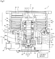
- Fig. 1 is a diagram illustrating schematically a turbo-molecular pump 1 according to Embodiment 1.
- Fig. 1 illustrates a cross section of the turbo-molecular pump 1 along an axis line direction.
- Embodiment 1 there is explained an example of the turbo-molecular pump 1 on the basis of an example of a so-called composite-blade (composite-type) vacuum pump provided with a turbo-molecular pump section T and a thread groove-type pump section S.
- composite-blade composite-blade
- Embodiment 1 and Example 1 may be used in a vacuum pump having only either the turbo-molecular pump section T or the thread groove pump section S, and also in a vacuum pump wherein the thread groove is provided on the side of a rotary body.
- a casing 2 that forms a casing of the turbo-molecular pump 1 is shaped as a tube, and makes up the casing of the turbo-molecular pump 1 together with a base 3 that is provided at the bottom of the casing 2.
- a gas transfer mechanism namely a structure that performs the function of evacuating the turbo-molecular pump 1.
- the gas transfer mechanism in the turbo-molecular pump 1 comprises the turbo-molecular pump section T on the side of an inlet port 6, and a thread groove-type pump section S on the side of an outlet port 19.
- the structure that brings about that evacuation function comprises broadly a rotor portion rotatably supported and a stator portion fixed to the casing 2.
- a control device 48 for controlling the operation of the turbo-molecular pump 1, and provided outside the casing of the turbo-molecular pump 1, is connected to the latter via a dedicated line.
- the rotor portion comprises a shaft 11 rotated by a below-described motor section 10, and a rotor section 24.
- the shaft 11 is a solid-cylindrical rotary shaft (rotor shaft).
- a rotor section 24 is mounted, through a plurality of bolts 25, to the top end of the shaft 11.
- the rotor section 24 comprises, for instance, a rotary member disposed on the shaft 11.
- the rotor section 24 comprises rotor blades 21 provided on the side of the inlet port 6 (turbo-molecular pump section T), and a tubular member 29 provided on the side of the outlet port 19 (thread groove-type pump section S).
- the rotor blades 21 comprise a plurality of plates that extend radially from the rotor section 24 and are tilted at a predetermined angle with respect to a plane perpendicular to the axis line of the shaft 11.
- the rotor blades 21 of the turbo-molecular pump 1 are provided as a plurality of stages in the axis line direction.
- the rotor section 24 is made up of a metal such as stainless steel, or an aluminum alloy.
- the tubular member 29 comprises a member the outer peripheral face whereof is shaped as a tube.
- a motor section 10 rotating the shaft 11 is disposed halfway in the axis line direction of the shaft 11.
- the motor section 10 in the present embodiment comprises a DC brushless motor.
- a permanent magnet 10a is fixed to the site that makes up the motor section 10 in the shaft 11.
- the permanent magnet 10a is fixed in such a manner that, for instance, the N-pole and the S-pole thereof are disposed at 180° about the shaft 11.
- the permanent magnet 10a there are opposingly disposed, for instance, six electromagnets 10b at intervals of 60°, symmetrically with respect to the axis line of the shaft 11, with a predetermined gap (clearance) left between the electromagnets and the shaft 11.
- the permanent magnet 10a functions as a rotor section (rotor portion) of the motor section 10.
- the electromagnets 10b function as a stator section (stator portion) of the motor section 10.
- the turbo-molecular pump 1 comprises a sensor that detects the revolutions and the rotation angle (phase) of the shaft 11. Through the sensor, the control device 48 can detect the position of the magnetic poles of the permanent magnet 10a thereof fixed to the shaft 11.
- the control device 48 consecutively switches current in the electromagnets 10b of the motor section 10 in accordance with the position of the detected magnetic poles, to generate thereby a rotating magnetic field around the permanent magnet 10a of the shaft 11.
- the permanent magnet 10a fixed to the shaft 11 follows that rotating magnetic field, and rotates the shaft 11 as a result.
- a radial magnetic bearing section 8 and a radial magnetic bearing section 12 that pivotally support the shaft 11 in the radial direction, i.e. that support the load of the rotor portion in the radial direction, are respectively provided at the inlet port 6 side and the outlet port 19 side of the motor section 10.
- a thrust magnetic bearing section 20 that pivotally supports the shaft 11 in the axis line direction (thrust direction), i.e. that supports the load of the rotor portion in the thrust direction, is provided at the lower end of the shaft 11.
- the shaft 11 (the rotor portion) is supported in the radial direction (direction of the radius of the shaft 11), in a contact-less manner, by the radial magnetic bearing sections 8, 12, and is supported in the thrust direction (axial direction of the shaft 11), in a contact-less manner, by the thrust magnetic bearing section 20.
- the above magnetic bearings make up a so-called five-axis control-type magnetic bearing, such that the shaft 11 has only one degree of freedom, namely rotation about the axis line.
- the radial magnetic bearing section 8 for instance, four electromagnets 8b are opposingly disposed, at 90° intervals around the shaft 11.
- the electromagnets 8b are arranged with a gap (clearance) to the shaft 11.
- the value of the gap takes on a value arrived at in consideration of, for instance, the steady-state amount of vibration (runout amount) of the shaft 11, the spatial distance between the rotor section 24 and the stator section (stator portion), and the characteristics of the radial magnetic bearing section 8.
- a target 8a is formed in the shaft 11, opposing the electromagnets 8b.
- the target 8a is attracted by the magnetic force of the electromagnets 8b of the radial magnetic bearing section 8, as a result of which the shaft 11 is supported, in a contact-less manner, in the radial direction.
- the target 8a functions as a rotor section of the radial magnetic bearing section 8
- the electromagnets 8b function as a stator section of the radial magnetic bearing section 8.
- the radial magnetic bearing section 12 is configured in the same way as in the radial magnetic bearing section 8, specifically, in that a target 12a is attracted by the magnetic force of the electromagnets 12b of the radial magnetic bearing section 12, whereby the shaft 11 is supported, in a contact-less manner, in the radial direction.
- the thrust magnetic bearing section 20 floats the shaft 11 in the axial direction, through an interposed disc-like metallic armature disc 30 that is provided perpendicularly to the shaft 11.
- two electromagnets 20a, 20b are disposed opposing each other across the armature disc 30.
- the electromagnets 20a, 20b are arranged with a gap between the electromagnets 20a, 20b and the armature disc 30.
- This gap takes on a value arrived at in consideration of, for instance, the steady-state amount of vibration of the shaft 11, the spatial distance between the rotor section 24 and the stator section, and the characteristics of the thrust magnetic bearing section 20.
- the armature disc 30 is attracted by the magnetic force of the electromagnets 20a, 20b of the thrust magnetic bearing section 20, as a result of which the shaft 11 is supported, in a contact-less manner, in the thrust direction (axis line direction).
- Displacement sensors 9, 13 are respectively formed in the vicinity of the radial magnetic bearing sections 8, 12, in such a way so as to be capable of detecting displacement of the shaft 11 in the radial direction.
- a displacement sensor 17 is formed at the lower end of the shaft 11 in such a way so as to be capable of detecting the displacement of the shaft 11 in the axis line direction.
- the displacement sensors 9, 13 are elements that detect the displacement of the shaft 11 in the radial direction.
- the displacement sensors 9, 13 are inductive-type sensors, such as eddy current sensors or the like, provided with coils 9b, 13b.
- the coils 9b, 13b of the displacement sensors 9, 13 make up part of an oscillation circuit formed in the control device 48 that is disposed outside the turbo-molecular pump 1.
- a high-frequency current flows through the displacement sensor 9, whereupon the latter generates a high-frequency magnetic field at the shaft 11.
- the oscillation amplitude of the oscillation circuit changes accompanying changes of the distance between the displacement sensors 9, 13 and the targets 9a, 13a.
- the displacement sensor can detect the displacement of the shaft 11 thereby.
- the sensor used for detecting the displacement of the shaft 11 is not particularly limited to the above, and may be, for instance, a capacitive sensor, an optical sensor or the like.
- control device 48 Upon detection of displacement of the shaft 11 in the radial direction, according to signals from the displacement sensors 9, 13, the control device 48 adjusts the magnetic force of the electromagnets 8b, 12b of the radial magnetic bearing sections 8, 12, whereby the shaft 11 returns to a predetermined position.
- control device 48 performs feedback control of the radial magnetic bearing sections 8, 12 on the basis of signals from the displacement sensors 9, 13.
- the shaft 11 levitates magnetically in the radial direction, with a predetermined gap (clearance) to the electromagnets 8b, 12b.
- the shaft 11 is thus held the space, in a contact-less manner, in the radial magnetic bearing sections 8, 12.
- the displacement sensor 17 comprises a coil 17b. Displacement in the thrust direction is detected through detection of the distance to a target 17a that is provided on the side of the shaft 11 opposing the coil 17b.
- control device 48 Upon detection of displacement of the shaft 11 in the thrust direction, on the basis of a signal from the displacement sensor 17, the control device 48 adjusts the magnetic force of the electromagnets 20a, 20b of the thrust magnetic bearing section 20, whereby the shaft 11 returns to a predetermined position.
- control device 48 performs feedback control of the thrust magnetic bearing section 20 on the basis of a signal from the displacement sensor 17.
- the shaft 11 levitates magnetically in the thrust direction, with a predetermined gap (clearance) to the electromagnets 20a, 20b, in the thrust magnetic bearing section 20.
- the shaft 11 is thus held in space in a contact-less manner.
- the shaft 11 is held by the radial magnetic bearing sections 8, 12 in the radial direction, and is held by the thrust magnetic bearing section 20 in the thrust direction.
- the shaft 11 rotates as a result in such a way so as to rotate about the axis line.
- a gas transfer mechanism namely the stator section (stator portion) having a structure for performing an evacuation function, is formed inside the casing 2 and the base 3.
- the stator section comprises, for instance, stator blades 22 provided on the side of the inlet port 6 (turbo-molecular pump section T), a thread groove spacer 5 provided on the side of the outlet port 19 (thread groove-type pump section S), as well as a stator column 18.
- the stator blades 22 comprise a plurality of plates that extend from the inner peripheral face of the casing 2 towards the shaft 11 and that are tilted at a predetermined angle with respect to a plane perpendicular to the axis line of the shaft 11.
- stator blades 22 are formed at a plurality of stages, alternately with the rotor blades 21, in the axis line direction.
- the stator blades 22 of each stage are spaced apart from each other by tubular spacers 23.
- the thread groove spacer 5 is a tubular member having a helical groove 7 formed in the inner peripheral face, and formed to a thinner wall thickness on the side of the outlet port 19 (in the vicinity of the base 3).
- a clearance 90 is provided between the base 3 (or casing 2) and the outer peripheral face of the thread groove spacer 5, at a site where the wall of the latter is thinner.
- a vibration sensor 100 is provided, taking advantage of the clearance 90, at the outer peripheral face of the thread groove spacer 5, at a site where the wall of the latter is thinner.
- the vibration sensor 100 functions as a contact detection means for detecting contact between the rotor portion and the stator portion inside the turbo-molecular pump 1.
- the vibration sensor 100 comprises, for instance, an acceleration pickup, a piezoelectric element, a moving coil, a strain gauge or the like.
- a sensitivity adjustment device (sensitivity adjustment function) of the vibration sensor 100 is built into the turbo-molecular pump 1.
- the conversion rate conversion sensitivity
- conversion sensitivity conversion sensitivity
- the sensitivity of the vibration sensor 100 does not have to be adjusted every time that a combination of the control device 48 is modified (connection to another control device 48).
- the inner peripheral face of the thread groove spacer 5 opposes the outer peripheral face of the tubular member 29, with a predetermined gap left in between.
- the direction of the helical groove 7 formed in the thread groove spacer 5 is the direction in which gas moves towards the outlet port 19, in a case where gas is transported, along the helical groove 7, in the rotation direction of the rotor section 24.
- the depth of the helical groove 7 is set so as to grow shallower nearer the outlet port 19.
- the base 3 comprises the casing 2 as well as the casing of the turbo-molecular pump 1.
- the motor section 10 and the radial magnetic bearing sections 8, 12 are disposed inside the stator column 18.
- a protective bearing 40 is provided on the inlet port 6 side of the displacement sensor 9, and a protective bearing 49 is provided on the outlet port 19 side of the displacement sensor 13.
- the protective bearings 40, 49 are bearings for supporting the shaft 11, for instance upon startup and stop of the turbo-molecular pump 1, or at times when the radial magnetic bearing sections 8, 12 and/or the thrust magnetic bearing section 20 are not working normally (touchdown), for instance during a power outage.
- the turbo-molecular pump 1 having the above-described configuration is used as a vacuum pump during evacuation of a vacuum vessel, for instance a process chamber or the like the interior of which is kept at a high vacuum and in which there is provided, for instance, a semiconductor manufacturing device.
- the turbo-molecular pump 1 sucks and evacuates a process gas from the interior of the process chamber.
- the process gas is introduced into the chamber while at a high temperature, for increasing reactivity. While being evacuated, however, part of the process gas condenses into a solid product, in the turbo-molecular pump 1, when pressure is equal to or greater than a given pressure, or through cooling. This solid product forms deposits that adhere to flow path surfaces in the turbo-molecular pump 1.
- the spacing between the rotor portion and the stator portion in the turbo-molecular pump 1, for instance the spacing between the rotor blades 21 and the stator blades 22, and the spacing between the tubular member 29 and the thread groove spacer 5, is very narrow.
- the rotor portion and the stator portion may come into contact with each other, through the above-described solid product, when the solid product forms deposited at the clearance between the rotor portion and the stator portion in an amount equal to or greater than a predetermined amount.
- the rotor portion in the turbo-molecular pump 1 rotates at high speed, at several tens of thousands rpm.
- contact between the rotor portion and the stator portion may give rise to, for instance, deformation and breakage (destruction).
- Embodiment 1 will be explained first with reference to Fig. 1 and Fig. 2 .
- control device 48 specifically, contact between the rotor portion and the stator portion of the turbo-molecular pump 1 is detected when the vibration detected by the vibration sensor 100 satisfies any of the conditions below:
- contact between the stator portion and the rotor portion may also be detected for instance in cases where phenomena that satisfy the above conditions occur a plurality of times within a predetermined lapse of time, or occur continuously over a predetermined lapse of time.
- the control device 48 is configured in such a way so as to issue an alarm signal, denoting an abnormal state, when the above-described vibration is detected (sensed) by the vibration sensor 100.
- the turbo-molecular pump 1 of the present embodiment automatically stops running, in order to prevent breakage of the parts.
- control device 48 may be provided with a timer function, such that operation of the turbo-molecular pump 1 is stopped when the alarm signal is issued continuously for a time equal to or longer than a predetermined time.
- the alarm signal may be set to be issued when the time interval (detecting timing interval) at which the above-described vibration is detected (sensed) by the vibration sensor 100 shrinks over time and becomes shorter than a predetermined interval time (period).
- the alarm signal may be set to be issued only when the revolutions at which contact is detected exceeds predetermined revolutions (threshold value), or only when an integrated value of the time over which contact is detected exceeds a predetermined time (threshold value).
- the timing at which an alarm signal is issued is limited by one of the three cases listed in claim 1.
- the approach of a maintenance period can be notified in advance through issuing of an alarm signal over a plurality of times (for instance, in two stages), so as to prevent the turbo-molecular pump 1 from becoming unusable all of a sudden.
- an alarm signal is issued that informs about an early stage of contact between the rotor portion and the stator portion.
- An alarm signal is issued thereafter that notifies that contact has progressed to a stage at which the turbo-molecular pump 1 is automatically stopped (or stoppage is urged).
- the timing at which there are generated such alarm signals denoting level differences in the degree of contact may be set arbitrarily, on the basis of, for instance, the revolutions at which contact is detected, an integrated value of the time over which contact is detected, or variations in the contact detection intervals.
- the alarm signal may be issued in accordance with the contact level, while under monitoring of the timing at which the above contact cycle intervals, i.e. contact detection intervals, become transiently shorter.
- the operation of the turbo-molecular pump 1 can be stopped at an appropriate period (timing), through issuing of an alarm signal, in a case where the vibration sensor 100 detects a particular vibration during contact between the rotor portion and the stator portion such as the one described above. This allows forestalling damage (breakage) of the parts of the turbo-molecular pump 1, and allows reducing the running costs of the turbo-molecular pump 1, while improving safety.
- the purpose of the above-described determination conditions in per (1) to (5) is to grasp not only vibration amplitude, but also particular vibrations that occur during contact between the rotor portion and the stator portion, and to distinguish (identify) the latter from vibration caused by growing unbalance over time and/or by external vibration.
- Vibration is induced between the rotor portion and the stator portion due to the shock there between when the two come into contact.
- the occurrence or not of contact between the rotor portion and the stator portion is determined on the basis of a component of that induced vibration.
- the natural frequency of parts according to the above conditions includes also the natural frequency derived from the site at which the part is integrally formed, and the natural frequency derived from (due to) the rigidity of the mounting section of the part.
- vibration detection of some parts at the natural frequency involves grasping a peak value of vibration within a frequency range having a given degree of clearance (margin).
- a signal that is been converted to an electric signal by a detection means such as the vibration sensor 100 is extracted by a bandpass filter that lets an envisaged frequency band through, and the magnitude of the extracted signal is compared against a predetermined threshold value, to determine thereby the occurrence or not of contact between the rotor portion and the stator portion.
- the predetermined threshold value in the condition set forth in per (2) is set to a value that allows appropriately excluding such a vibration level, at the natural frequency of the parts that make up the rotary body and that is normally transmitted towards the stator portion.
- the natural frequency of parts that make up the rotary body changes in accordance with the revolutions, due to the action of the centrifugal force and gyroscopic moment.
- the characteristic (pass band characteristic) of the above-described bandpass filter is modified beforehand in accordance with the revolutions of the rotor portion.
- mapping information on how the filter characteristic changes in accordance with the revolutions is stored beforehand in the control device 48, and the settings of the filter that is used are modified on the basis of the mapping information.
- a bandpass filter having an expanded frequency band in response to envisaged changes in the natural frequency, although in this case detection precision is lower.
- the predetermined threshold value in the condition set forth in (3) is set to a value that allows appropriately excluding such a vibration level that is normally transmitted towards the stator portion.
- the configuration of the detection means for detecting contact between the rotor portion and the stator portion inside the turbo-molecular pump 1 is not particularly limited to that of the above embodiment.
- Fig. 2A illustrates a Variation 1 of the Embodiment 1.
- a vibration sensor 101 may be provided on the outer peripheral face of the base 3, so that vibration is detected using two sensors, i.e. the vibration sensor 100 and the vibration sensor 101.
- the vibration sensor 100 is disposed on the thread groove spacer 5, and the vibration sensor 101 is disposed on the base 3 to which the thread groove spacer 5 is fixed.
- the vibration sensor 101 is disposed at a different part (base 3) that is built on a part (thread groove spacer 5) at which the vibration sensor 100 is disposed. That is, the vibration sensors 100, 101 are disposed not on a same part comprised in the stator portion, but at respective parts having a different build-up order.
- the vibration sensor 101 provided at the outer peripheral face of the turbo-molecular pump 1 (base 3), as illustrated in Fig. 2A , can sense more distinctly vibration caused by external shocks (disturbances).
- Vibration generated upon contact between the rotor portion and the stator portion is greatest at the contact portion, and tends to decrease gradually away from the contact portion, due to vibration damping at transmitting parts. This relationship is reversed for extraneous vibration.
- Variation 1 of Embodiment 1 therefore, the above characteristic is exploited by further providing the vibration sensor 101 at a part that is physically spaced apart from the contact portion, and by predominantly grasping contact-derived vibration on the basis of the difference (differential signal) between signals obtained from the vibration sensor 101 and the vibration sensor 100.
- the vibration sensor 101 which detects a comparative signal resulting from calculating a differential signal vis-à-vis the vibration sensor 100, is disposed at the base 3 that is built up on the thread groove spacer 5.
- the site at which the vibration sensor 101 is disposed is not limited to the above-described one, and the vibration sensor 101 may be provided at another stator portion (for instance, the casing 2) that is built up on the thread groove spacer 5.
- Embodiment 1 dealt with an instance where the vibration sensor 100 that detects vibration is disposed directly on the thread groove spacer 5.
- the way in which the vibration sensor 100 is disposed is not limited to the above-described one.
- Fig. 2B is a diagram illustrating a Variation 2 of the Embodiment 1.
- a vibration sensor 50 may be disposed on the stator portion via a plate-like brace 60 that is mounted to the thread groove spacer 5.
- the brace 60 having an L-shaped cross section may be mounted to a shoulder formed on the thread groove spacer 5, on the side of the outlet port 19, in such a manner that the long limb of the L-shape is parallel to the outer peripheral wall of the thread groove spacer 5.
- the vibration sensor 100 is then disposed on the side face of the long limb of the L-shape of the brace 60.
- the brace 60 is configured in such a manner that the natural frequency of the brace 60 itself is an induced vibration frequency according to the determination conditions in per (1) to (5) above, or a frequency that is an approximate multiple of the induced vibration.
- the vibration sensor 100 is disposed via the brace 60 in order to grasp an enlarged (amplified) vibration induced at the site on a stator portion side.
- the vibration (amplitude) generated in the turbo-molecular pump 1 can be easily amplified as a result, which in turn allows increasing the vibration detection precision.
- the extracted vibration frequency can be appropriately narrowed down by providing the vibration sensor 100 via the brace 60. This allows increasing the vibration detection precision.
- the vibration level at the natural frequency of the brace 60 is significantly large within the vibration detected by the vibration sensor 100 upon occurrence of contact between the rotor portion and the stator portion inside the turbo-molecular pump 1. Therefore, the occurrence or not of contact between the rotor portion and the stator portion can be sufficiently determined by monitoring (controlling) the vibration level (amplitude magnitude) at the natural frequency of the brace 60, as a part that makes up the stator portion.
- the stator portion (thread groove spacer 5') at which the vibration sensor 100 is disposed may be fixed to the casing (casing 2, base 3) through a vibration damping member (elastomer) having a higher (greater) vibration damping coefficient than that of the fixed member at which the vibration sensor 100 is disposed.
- Fig. 2C is a diagram illustrating a Variation 3 of the Embodiment 1. As illustrated in Fig. 2C , specifically, an elastic member 70 is disposed between the outer peripheral side face of the thread groove spacer 5' and the inner peripheral side face of the base 3.
- An elastic member 71 is disposed between the mounting face of the base 3 and a flange-like mounting section 50, for the base 3, disposed on the inlet port 6 side of the thread groove spacer 5'.
- a washer 72 of a bolt 80 that fixes (fastens) the mounting section 50 of the thread groove spacer 5' against the base 3 comprises an elastic body.
- the vibration level transmitted from outside can be thus reduced by fixing the stator portion (thread groove spacer 5'), at which the vibration sensor 100 is mounted, to the casing via the elastic members 70, 71, and via the elastic washer 72, that have a vibration absorption (vibration damping) function. This allows increasing as a result the sensing precision of the particular vibration generated during contact between the rotor portion and the stator portion.
- the vibration absorption (vibration damping) member comprises a resin-made member of, for instance, rubber, plastic or the like.
- a structure that uses such a vibration damping member may be used not only in Variation 3 of Embodiment 1, but also in any of the other above-described variations.
- Embodiment 1 and variations thereof described above there have been explained instances where the vibration sensor 100 for detecting the particular vibration that occurs upon contact between the rotor portion and the stator portion is mounted on a portion at which the rotor portion and the stator portion are likely to come into contact, i.e. a portion in the vicinity of a downstream side (outlet port 19 side) of a gas transfer path at which solid products are likely to deposit.
- the vibration sensor 100 may be provided at another stator portion that opposes the rotor portion, for instance, on the stator blades 22 or the spacers 23.
- contact may be detected on the basis of a differential signal with respect to the vibration sensor 101 disposed on the base 3 or the casing 2; the vibration sensor 100 may be mounted via a brace; and a vibration damping member may be provided against the casing.
- Embodiment 1 and Variations 1 to 3 thereof an instance where the vibration sensor 100 is disposed on the stator portion side has been explained as a method for detecting contact between the rotor portion and the stator portion inside the turbo-molecular pump 1.
- the method for detecting the particular vibration that occurs during contact between the rotor portion and the stator portion is not limited to the above-described one.
- the occurrence or not of contact between the rotor portion and the stator portion may also be detected by detecting the vibration of the rotor portion, i.e. the change over time of the displacement of the rotor portion.
- a sensor that monitors the displacement of the rotor portion (rotary body), for instance, the shaft 11, the rotor section 24 (rotor blades 21, tubular member 29), such that the occurrence or not of contact between the rotor portion and the stator portion is determined on the basis of the detection results (detecting results) of this sensor.
- the sensor may comprise, for instance, an inductive-type, an eddy current-type, a capacitive-type or optical-type contact-less displacement sensor that converts the vibration of the rotor portion into an electric signal.
- the sensor (contact-less sensor) for detecting contact between the rotor portion and the stator portion may be configured so as to double as the displacement sensors 9, 13 used for controlling the radial magnetic bearing sections 8, 12.
- the occurrence or not of contact between the rotor portion and the stator portion can be determined through direct monitoring of the vibration of the rotor portion.
- detecting by the sensor may be configured, as in Embodiment 1 above, in such a manner so as to sense the occurrence of contact between the rotor portion and the stator portion in cases where phenomena that satisfy the above conditions occur a plurality of times within a predetermined lapse of time, or occur continuously over a predetermined lapse of time.
- this brace member is disposed at a site where contact with the stator portion is anticipated.
- the vibration (amplitude) occurring in the turbo-molecular pump 1 can be easily amplified by detecting the vibration of the rotor portion through the brace member. This allows enhancing the vibration detection precision.
- Example 1 not part of the invention will be explained first with reference to Fig. 3 to Fig. 7 .
- elements identical to those of Embodiment 1 will be denoted with the same reference numerals, and an explanation thereof will be omitted.
- a sensitivity adjustment device 103 is provided on the inner peripheral face of the substantially tubular base 3.
- the arrangement position of the sensitivity adjustment device 103 is not limited thereto, and the sensitivity adjustment device 103 may be disposed at or inside the casing, for instance at a in-pump board 104 that is fixed to the thrust magnetic bearing section 20, or at a rear cap 105 that covers the opening of the base 3, or at the outer peripheral face of the casing (casing 2, base 3).
- the sensitivity adjustment device 103 on the side of the main body of the turbo-molecular pump 1', the sensitivity of the vibration sensor 102 does not have to be adjusted every time that a combination of the control device 48 is modified (connection to another control device 48).
- replacement of the turbo-molecular pump 1' no longer requires, for instance, a measurement instrument or the like for sensitivity adjustment. The replacement operation can be made thus simpler and more convenient.
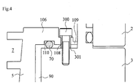
- Fig. 4 is an enlarged diagram of the portion of broken line A illustrated in Fig. 3 .
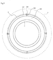
- Fig. 5 is a plan-view diagram of the thread groove spacer 5 mounted to the base 3, viewed from the inlet port 6.
- the details of the method for mounting the thread groove spacer 5 are explained next.
- the thread groove spacer 5 is mounted to the base 3 through a plurality of bolts 300, via an O-ring 200.
- an outward-flaring ring-like flange section 106 for fixing is provided at an end of the thread groove spacer 5, on the inlet port 6 side of the tubular shape of the inner peripheral face of the thread groove spacer 5 at which the helical groove 7 is formed.
- a ring-like mounting section 107, thinner than the flange section 106, is provided at the outer peripheral edge of the flange section 106.
- four bolt holes 108 for insertion of the fixing bolts 300 are equidistantly formed along the circumference of the mounting section 107.
- claws 109 for positioning the thread groove spacer 5 are provided in the mounting section 107, protruding from the outer peripheral edge of the latter towards the casing 2, the four claws 109 being equidistantly formed along the circumference of the mounting section 107.
- the claws 109 are formed so as to have a sufficiently small contact surface area with the casing (casing 2, base 3) in order to suppress the influence of extraneous vibration that is transmitted from the casing to the thread groove spacer 5.
- a ring groove 110 for fitting and fixing the O-ring 200 is formed along the circumferential direction of the thread groove spacer 5, in the surface of the outlet port 19 side of the flange section 106.
- the flange section 106 is fixed to the end face of the base 3, on the side of the inlet port 6, through the bolts 300, in a state where the O-ring 200 is fitted and fixed (temporarily fixed) to the ring groove 110.
- tubular bushes (bushings) 301 for preventing direct contact between the thread groove spacer 5 (mounting section 107) and the bolts 300 are disposed in the bolt holes 108, with a view to suppressing the influence of extraneous vibration that is transmitted from the casing (casing 2, base 3) to the thread groove spacer 5, via the bolts 300.
- the thread groove spacer 5 is mounted to the base 3 in a state where the bolts 300 are inserted into the bushes 301.
- the O-ring 200 that is used is an elastic member having vibration damping characteristics, for instance made of a fluororesin, and has a shape such that the cross-sectional diameter thereof is large enough to prevent contact between the thread groove spacer 5 and the base 3 during fixing of the thread groove spacer 5 to the base 3.
- the O-ring 200 is formed out of a material that falls under the category "4-D" according to JIS standards.
- the bushes 301 are also elastic members having vibration damping characteristics, and are formed, for instance, of nylon.
- the thread groove spacer 5 is fixed to the casing (casing 2, base 3) with an elastic member disposed in between.
- the method for mounting the thread groove spacer 5 is not limited to the above-described one.
- Figs. 6A and 6B are diagrams illustrating variations of the method for mounting the thread groove spacer 5 in Embodiment 2.
- elements identical to those Fig. 1 and Fig. 4 will be denoted with the same reference numerals, and an explanation thereof will be omitted.
- a ring groove 201 for fitting and fixing an O-ring 200 may be formed along the circumferential direction of the end face of the base 3, on the inlet port 6 side, and not in the thread groove spacer 5.
- the ring grooves 110 ( Fig. 4 ), 201 ( Fig. 6 ) for fitting and fixing the O-ring 200 may be provided on both the thread groove spacer 5 and the end face of the base 3 on the side of the inlet port 6.
- the O-ring 200 that is used has a shape such that the cross-sectional diameter thereof is large enough to prevent contact between the thread groove spacer 5 and the base 3 during fixing of the thread groove spacer 5 to the base 3.
- annular flat plate-like elastic body 202 having vibration damping characteristics may be disposed, instead of the O-ring 200, between the thread groove spacer 5 and the end face of the base 3 on the side of the inlet port 6.
- the thread groove spacer 5 may be fixed in such a manner that the annular flat plate-like elastic body 202, formed at a position at which the bolt holes 203 for insertion of bolts 300 and the bushes 301 correspond to the four circumferentially equidistant bolt holes 108, is sandwiched between the end face of the base 3 on the side of the inlet port 6, and the face of the mounting section 107 on the side of the outlet port 19.
- Example 1 deals with an instance in which the thread groove spacer 5 is fixed through four bolts 300.
- the number of fixing sites for the bolts 300 is not limited thereto, and need only be at least three sites or more, from the viewpoint of fixing stability.
- the number of fixing sites of the bolts 300 is preferably small, in order to suppress the influence of extraneous vibration that propagates from the casing (casing 2, base 3) to the thread groove spacer 5.
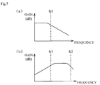
- Fig. 7A is a graph illustrating the vibration propagation characteristic of the elastic member.
- the elastic member has a frequency characteristic of a low-pass filter having a cutoff frequency fc1 (Hz).
- the elastic member has a characteristic whereby vibration caused by an shock (disturbance) exerted from outside onto the casing and having a frequency smaller than fc1 (Hz) is not damped, but propagates towards the thread groove spacer 5, while external vibration having a frequency equal to or greater than fc1 (Hz) is damped by 20 dB/decad, and does not propagate readily towards the thread groove spacer 5.
- the above-mentioned cutoff frequency of the elastic member takes on a value that is set on the basis of, for instance, the rigidity thereof in a state where the elastic member is disposed between the thread groove spacer 5 and the casing (casing 2, base 3).
- control device 48 is provided with an A/D conversion circuit, not shown, that converts an analog vibration signal outputted by the vibration sensor 102 into a digital vibration signal.
- the control device 48 is also provided with a DSP-based supervisor circuit, not shown, and which receives a vibration signal digitalized by the A/D conversion circuit.
- the supervisor circuit is programmed so as to detect contact between the rotor portion and the stator portion in the turbo-molecular pump 1'.
- a digital filter is built into the supervisor circuit, such that a vibration signal of a predetermined pass band frequency is extracted when the digital vibration signal is inputted into the digital filter.
- the supervisor circuit is programmed in such a manner that contact between the stator portion and the rotor portion in the turbo-molecular pump 1' is detected to have occurred if the vibration level of the vibration signal having passed through the digital filter (extracted vibration signal) exceeds a predetermined threshold value.
- Fig. 7B is a graph illustrating a vibration signal damping characteristic of the digital filter in the supervisor circuit.
- the digital filter has a frequency characteristic of a bandpass filter the pass band of which is fc1 to fc2 (Hz).
- the digital filter has a characteristic whereby vibration signals having a frequency smaller than fc1 (Hz), and vibration signals having a frequency greater than fc2 (Hz), from among inputted vibration signals, are damped and outputted, i.e. a characteristic whereby only vibration signals between fc1 (Hz) and fc2 (Hz) are outputted.
- fc1 which denotes the lower limit of the pass band of the digital filter, is set so as to match the cutoff frequency of the above-described elastic member (O-ring 200, elastic body 202) disposed between the thread groove spacer 5 and the casing (casing 2, base 3).
- the digital filter allows damping external vibration that is not damped by the elastic member and that propagates to the thread groove spacer 5, and damping also the resonant vibration component generated upon acceleration and deceleration of the turbo-molecular pump 1'.
- the cutoff frequency (fc1) of the elastic member is set to about 100 (Hz) in consideration of the band of resonant vibration that arises upon acceleration and deceleration of the turbo-molecular pump 1'.
- Example 1 thus, the occurrence or not of contact between the stator portion and the rotor portion is determined through comparison of the vibration signal that passes through the digital filter versus a predetermined threshold value.
- occurrence or not of contact between the stator portion and the rotor portion is determined on the basis of a vibration signal in a band that contains no (a small) external vibration component, namely a vibration signal of a band unaffected (little affected) by the influence of external vibration, thanks to the action of the elastic member disposed between the thread groove spacer 5 and the casing.
- the occurrence or not of contact between the stator portion and the rotor portion is determined on the basis of vibration signals of a band in which there remains (from which there is extracted) a component of shock or vibration caused by contact between the stator portion and the rotor portion.
- Example 1 occurrence or not of contact between the stator portion and the rotor portion, i.e., whether the amount of deposited solid product has reached the clearance between the rotor portion and the stator portion, can be detected using a simple configuration such as the above-described one.
- Example 1 a bandpass filter is used as the method for extracting a band in which there remains (from which there is extracted) a component of shock or vibration caused by contact between the stator portion and the rotor portion.
- the bandpass filter there can be used a high-pass filter having a cutoff frequency fc1 (Hz) that allows removing at least an external vibration component and a resonant vibration component generated upon acceleration and deceleration of the turbo-molecular pump 1'.
- control device 48 (supervisor circuit)detects contact between the stator portion and the rotor portion in the turbo-molecular pump 1', the control device 48 issues an alarm signal that denotes an abnormal state.
- the turbo-molecular pump 1' of Example 1 Upon issuing of the above alarm signal, the turbo-molecular pump 1' of Example 1 automatically stops running, in order to prevent breakage of the parts.
- control device 48 may be provided with a timer function, such that operation of the turbo-molecular pump 1' is stopped when the alarm signal is issued continuously for a time equal to or longer than a predetermined time.
- the alarm signal may be set to be issued when the time interval (detecting timing interval) at which the above-described vibration is detected (sensed) by the vibration sensor 102 shrinks over time and becomes shorter than a predetermined interval time (period).
- the alarm signal may be set to be issued only when the revolutions at which contact is detected exceeds predetermined revolutions (threshold value), or only when an integrated value of the time over which contact is detected exceeds a predetermined time (threshold value).
- the timing at which an alarm signal is issued is not limited to the above conditions.
- the approach of a maintenance period can be notified in advance through issuing of an alarm signal over a plurality of times (for instance, in two stages), so as to prevent the turbo-molecular pump 1' from becoming unusable all of a sudden.
- an alarm signal (a contact notification signal) is issued that informs about an early stage of contact between the rotor portion and the stator portion.
- An alarm signal is issued thereafter that notifies that contact has progressed to a stage at which the turbo-molecular pump 1' is automatically stopped (or stoppage is urged).
- the timing at which there are generated such alarm signals denoting level differences in the degree of contact may be set arbitrarily, on the basis of, for instance, the revolutions at which contact is detected, an integrated value of the time over which contact is detected, or variations in the contact detection intervals.
- the alarm signal may be issued in accordance with the contact level, while under monitoring of the timing at which the above contact cycle intervals, i.e. contact detection intervals, become transiently shorter.
- the operation of the turbo-molecular pump 1' can be stopped at an appropriate period (timing), through issuing of an alarm signal, or of a contact notification signal, in a case where the vibration sensor 102 detects a particular vibration during contact between the rotor portion and the stator portion such as the one described above.
- This allows forestalling damage (breakage) of the parts of the turbo-molecular pump 1', and allows reducing the running costs of the turbo-molecular pump 1', while increasing safety.
- the sensitivity adjustment device 103 of the vibration sensor 102 is built into the main body of the turbo-molecular pump 1', and thus the sensitivity of the vibration sensor 102 does not have to be adjusted every time.
- the method for doing away with the need for adjusting every time the sensitivity of the vibration sensor 102 is not limited to the above-described one.
- an adjustment value of the detection signal level of the vibration sensor 102 set upon shipment from the factory may be stored in a storage device built into the main body of the turbo-molecular pump 1', instead of building the sensitivity adjustment device 103 into the main body of the turbo-molecular pump 1', such that upon modification of the combination of the control device 48, the control device 48 performs correction by reading, from the storage device, the adjustment value of the detection signal level of the vibration sensor 102.
- the adjustment value of the detection signal level of the vibration sensor 102 is preferably stored in, for instance, a memory mounted on an in-pump board 104.
- Example 1 the output signal of the vibration sensor 102 is converted to a digital signal.
- the processing method of the output signal of the vibration sensor 102 is not limited thereto.
- the process for detecting contact between the rotor portion and the stator portion may be configured so as to use analog signals unconverted to digital signals.
- an analog filter having the same characteristic as the above-described digital filter is used instead of the latter.
- Example 1 there have been explained instances where the vibration sensor 102 for detecting the particular vibration that occurs upon contact between the rotor portion and the stator portion is mounted on a portion at which the rotor portion and the stator portion are likely to come into contact, i.e. a portion in the vicinity of a downstream side (outlet port 19 side) of a gas transfer path at which solid products are likely to deposit.
- the mounting site of the vibration sensor 102 is not limited to the above-described one.
- the vibration sensor 102 may be provided at another stator portion that opposes the rotor portion, for instance, on the stator blades 22 or the spacers 23.
- an elastic member is disposed between the casing and the stator portion at which the vibration sensor 102 is disposed.
Landscapes
- Engineering & Computer Science (AREA)
- Mechanical Engineering (AREA)
- General Engineering & Computer Science (AREA)
- Non-Positive Displacement Air Blowers (AREA)
- Structures Of Non-Positive Displacement Pumps (AREA)
- Control Of Positive-Displacement Air Blowers (AREA)
Claims (6)
- Pompe à vide, comprenant :un boîtier pourvu d'un orifice d'entrée et d'un orifice de sortie ;une partie statorique prévue à l'intérieur du boîtier ;une partie rotorique possédant un arbre (11) supporté de manière rotative à l'intérieur du boîtier, et un rotor (24) agencé sur l'arbre (11) et pourvue d'un mécanisme de transfert de gaz qui transfère un gaz depuis l'orifice d'entrée vers l'orifice de sortie, la partie rotorique étant agencée avec un jeu prédéterminé entre la partie rotorique et la partie statorique ;un moteur (10) faisant tourner l'arbre (11) ;des électroaimants (8b, 12b, 20a, 20b) supportant l'arbre (11) ;des capteurs de déplacement (9b, 13b, 17b) détectant le déplacement de l'arbre (11) ;caractérisée en ce que la pompe comprend :des moyens de détection de contact (100, 102, 48), comprenant des moyens de détection de vibrations (100) pour détecter des vibrations, lesquels moyens de détection de vibrations sont configurés à partir d'un capteur de vibrations agencé dans la partie statorique, sur un organe qui fait face à la partie rotorique et sont configurés pour détecter une occurrence de contact entre la partie statorique et la partie rotorique lorsque, dans les vibrations détectées par les moyens de détection de vibrations, une vibration spécifique causée par un contact entre la partie statorique et la partie rotorique dépasse une valeur seuil prédéterminée ; etdes moyens de sortie alarme (48) configurés pour émettre une alarme lorsque les moyens de détection de contact détectent une occurrence de contact entre la partie statorique et la partie rotorique, dans laquelle le moment où les moyens de sortie alarme émettent une alarme correspond à l'un quelconque des cas suivants :l'intervalle de temps pendant lequel la vibration causée par le contact est détecté diminue en fonction du temps et devient plus court qu'une durée d'intervalle prédéterminée ;le cas où le nombre de tours auxquels le contact est détecté dépasse un nombre de tours prédéterminé ; oule cas où une valeur intégrée de la durée pendant laquelle le contact est détecté dépasse une durée prédéterminée.
- Pompe à vide selon la revendication 1, dans laquelle
la vibration spécifique est une vibration d'au moins une fréquence parmi :une première fréquence qui correspond à une fréquence naturelle d'une pièce faisant partie de la partie statorique ;une seconde fréquence qui correspond à une fréquence naturelle d'une pièce faisant partie de la partie rotorique ;une troisième fréquence qui correspond à une fréquence qui est un multiple du nombre de tours (fréquence) de la partie rotorique ;une quatrième fréquence qui correspond à une fréquence de battement des vibrations des première à troisième fréquences ; etune cinquième fréquence, dans une plage spécifique, générée au contact entre la partie rotorique et la partie statorique. - Pompe à vide selon l'une quelconque des revendications 1 et 2, dans laquelle
les moyens de détection de vibrations sont configurés à partir d'une pluralité de capteurs de vibrations (100, 101, 102) agencés à différents endroits de la partie statorique, et détectent l'occurrence d'un contact entre la partie statorique et la partie rotorique en se basant sur les différences dans les vibrations détectées par les capteurs de vibrations (100, 101, 102). - Pompe à vide selon l'une quelconque des revendications 1 à 3, dans laquelle
la partie statorique sur laquelle les moyens de détection de vibrations sont prévus est fixée au boîtier à travers un organe élastique (70, 71). - Pompe à vide selon la revendication 1 ou 2, dans laquelle
les moyens de détection de vibrations détectent, comme une vibration, un changement en fonction du temps d'un déplacement de position de la partie rotorique. - Pompe à vide selon la revendication 5, dans laquelle
les moyens de détection de vibrations sont configurés à partir d'un capteur de déplacement sans contact qui détecte un déplacement de la partie rotorique.
Applications Claiming Priority (3)
| Application Number | Priority Date | Filing Date | Title |
|---|---|---|---|
| JP2008182364 | 2008-07-14 | ||
| JP2008182365 | 2008-07-14 | ||
| PCT/JP2009/062708 WO2010007975A1 (fr) | 2008-07-14 | 2009-07-14 | Pompe à vide |
Publications (3)
| Publication Number | Publication Date |
|---|---|
| EP2314877A1 EP2314877A1 (fr) | 2011-04-27 |
| EP2314877A4 EP2314877A4 (fr) | 2015-03-11 |
| EP2314877B1 true EP2314877B1 (fr) | 2018-08-22 |
Family
ID=41550378
Family Applications (1)
| Application Number | Title | Priority Date | Filing Date |
|---|---|---|---|
| EP09797900.9A Not-in-force EP2314877B1 (fr) | 2008-07-14 | 2009-07-14 | Pompe à vide |
Country Status (5)
| Country | Link |
|---|---|
| US (1) | US8690525B2 (fr) |
| EP (1) | EP2314877B1 (fr) |
| JP (1) | JP5719592B2 (fr) |
| KR (1) | KR101629979B1 (fr) |
| WO (1) | WO2010007975A1 (fr) |
Families Citing this family (33)
| Publication number | Priority date | Publication date | Assignee | Title |
|---|---|---|---|---|
| KR101823696B1 (ko) * | 2010-05-21 | 2018-01-30 | 에드워즈 가부시키가이샤 | 배기 펌프의 퇴적물 검지 장치와, 그 장치를 구비한 배기 펌프 |
| EP2518456A1 (fr) * | 2011-04-29 | 2012-10-31 | ABB Technology AG | Procédé de surveillance de démagnétisation |
| WO2012165105A1 (fr) * | 2011-06-03 | 2012-12-06 | エドワーズ株式会社 | Pompe à vide |
| US11274671B2 (en) * | 2011-09-14 | 2022-03-15 | Roger L. Bottomfield | Turbine cap for turbo-molecular pump |
| CN102425563B (zh) * | 2011-12-08 | 2014-03-12 | 北京中科科仪股份有限公司 | 同步抑制磁悬浮分子泵转子次临界振动的方法和系统 |
| JP6058642B2 (ja) * | 2012-04-24 | 2017-01-11 | エドワーズ株式会社 | 排気ポンプの堆積物検知装置及び排気ポンプ |
| GB2507500B (en) * | 2012-10-30 | 2015-06-17 | Edwards Ltd | Vacuum pump |
| GB2507501B (en) * | 2012-10-30 | 2015-07-15 | Edwards Ltd | Vacuum pump |
| JP2014234726A (ja) * | 2013-05-31 | 2014-12-15 | エドワーズ株式会社 | メンテナンス予測装置とその予測方法 |
| JP6427963B2 (ja) * | 2014-06-03 | 2018-11-28 | 株式会社島津製作所 | 真空ポンプ |
| JP6436731B2 (ja) * | 2014-11-12 | 2018-12-12 | エドワーズ株式会社 | 真空ポンプ及び該真空ポンプの異常原因推定方法 |
| JP6616611B2 (ja) * | 2015-07-23 | 2019-12-04 | エドワーズ株式会社 | 排気システム |
| JP6391171B2 (ja) * | 2015-09-07 | 2018-09-19 | 東芝メモリ株式会社 | 半導体製造システムおよびその運転方法 |
| JP6692635B2 (ja) * | 2015-12-09 | 2020-05-13 | エドワーズ株式会社 | 連結型ネジ溝スペーサ、および真空ポンプ |
| JP6758865B2 (ja) * | 2016-03-04 | 2020-09-23 | エドワーズ株式会社 | 真空ポンプ |
| GB2551337A (en) * | 2016-06-13 | 2017-12-20 | Edwards Ltd | Pump assembly, method and computer program |
| JP7098882B2 (ja) * | 2017-04-03 | 2022-07-12 | 株式会社島津製作所 | 真空ポンプ |
| JP6948147B2 (ja) * | 2017-04-18 | 2021-10-13 | エドワーズ株式会社 | 真空ポンプ、真空ポンプに備わる磁気軸受部およびシャフト |
| JP7057128B2 (ja) * | 2017-12-28 | 2022-04-19 | エドワーズ株式会社 | 真空ポンプ及び真空ポンプの堆積物検知装置並びに真空ポンプの堆積物検知方法 |
| JP7096006B2 (ja) * | 2018-02-16 | 2022-07-05 | エドワーズ株式会社 | 真空ポンプと真空ポンプの制御装置 |
| JP7088688B2 (ja) * | 2018-02-16 | 2022-06-21 | エドワーズ株式会社 | 真空ポンプと真空ポンプの制御装置 |
| JP7006520B2 (ja) * | 2018-06-14 | 2022-01-24 | 株式会社島津製作所 | 真空ポンプおよび診断システム |
| JP7173856B2 (ja) * | 2018-12-19 | 2022-11-16 | 株式会社荏原製作所 | 電動機組立体 |
| EP3557072B1 (fr) * | 2019-02-27 | 2021-02-24 | Pfeiffer Vacuum Gmbh | Surveillance d'un dispositif de palier d'une pompe à vide |
| JP2021014834A (ja) * | 2019-07-12 | 2021-02-12 | エドワーズ株式会社 | 真空ポンプ、ロータ及び座金 |
| JP7377660B2 (ja) * | 2019-09-27 | 2023-11-10 | エドワーズ株式会社 | 真空ポンプ及び真空ポンプの付属ユニット |
| DE102019130981A1 (de) * | 2019-11-15 | 2021-05-20 | Seepex Gmbh | Exzenterschneckenpumpe |
| JP7766998B2 (ja) * | 2020-03-31 | 2025-11-11 | エドワーズ株式会社 | 真空ポンプ |
| JP7546412B2 (ja) * | 2020-08-21 | 2024-09-06 | エドワーズ株式会社 | 真空ポンプ、固定翼、およびスペーサ |
| JP7459811B2 (ja) * | 2021-01-25 | 2024-04-02 | 株式会社島津製作所 | 真空ポンプ |
| JP7680226B2 (ja) * | 2021-03-04 | 2025-05-20 | エドワーズ株式会社 | 真空ポンプ |
| JP7696946B2 (ja) * | 2023-04-27 | 2025-06-23 | エドワーズ株式会社 | 真空ポンプ及び真空ポンプの運転方法 |
| JP7762691B2 (ja) * | 2023-08-21 | 2025-10-30 | エドワーズ株式会社 | 真空ポンプの異常検知装置、真空ポンプシステムおよび真空ポンプの異常検知方法 |
Citations (1)
| Publication number | Priority date | Publication date | Assignee | Title |
|---|---|---|---|---|
| EP0851127A2 (fr) * | 1996-12-27 | 1998-07-01 | VARIAN S.p.A. | Procédé et dispositif de diagnostic pour pompes à vide |
Family Cites Families (18)
| Publication number | Priority date | Publication date | Assignee | Title |
|---|---|---|---|---|
| DE8703108U1 (de) * | 1987-02-28 | 1988-03-31 | Leybold AG, 5000 Köln | Vakuumpumpe mit einer Einrichtung zur Drehzahlmessung |
| JPH02145696U (fr) * | 1989-05-16 | 1990-12-11 | ||
| JPH06101655A (ja) | 1992-09-24 | 1994-04-12 | Nissan Edowaazu Shinku Kk | ドライシールド型真空ポンプ |
| JP3457353B2 (ja) | 1993-05-25 | 2003-10-14 | ビーオーシーエドワーズテクノロジーズ株式会社 | 磁気軸受装置 |
| US5469007A (en) * | 1993-12-07 | 1995-11-21 | Mitsubishi Jukogyo Kabushiki Kaisha | Magnetic bearing arrangement |
| US6213737B1 (en) * | 1997-04-18 | 2001-04-10 | Ebara Corporation | Damper device and turbomolecular pump with damper device |
| US7539549B1 (en) * | 1999-09-28 | 2009-05-26 | Rockwell Automation Technologies, Inc. | Motorized system integrated control and diagnostics using vibration, pressure, temperature, speed, and/or current analysis |
| JP4197819B2 (ja) * | 1999-02-19 | 2008-12-17 | 株式会社荏原製作所 | ターボ分子ポンプ |
| JP2000274391A (ja) * | 1999-03-23 | 2000-10-03 | Seiko Seiki Co Ltd | オーバーハング型ターボ分子ポンプ |
| JP2000283056A (ja) * | 1999-03-26 | 2000-10-10 | Hitachi Ltd | 真空ポンプ異常監視システム |
| JP2003021093A (ja) * | 2001-07-05 | 2003-01-24 | Boc Edwards Technologies Ltd | 真空ポンプ |
| JP2003097554A (ja) * | 2001-09-25 | 2003-04-03 | Ebara Corp | 磁気軸受制御装置 |
| JP2004117091A (ja) | 2002-09-25 | 2004-04-15 | Boc Edwards Technologies Ltd | 真空ポンプ |
| JP2004150340A (ja) * | 2002-10-30 | 2004-05-27 | Mitsubishi Heavy Ind Ltd | ターボ分子ポンプおよびその故障予測方法 |
| JP2005105846A (ja) * | 2003-09-26 | 2005-04-21 | Boc Edwards Kk | 真空ポンプ |
| GB0508872D0 (en) * | 2005-04-29 | 2005-06-08 | Boc Group Plc | Method of operating a pumping system |
| DE102006034478A1 (de) * | 2006-07-26 | 2008-01-31 | Oerlikon Leybold Vacuum Gmbh | Verfahren zur Ermittlung einer Aussage über einen Zustand einer Turbomolekularpumpe sowie eine Turbomolekularpumpe |
| JP5126186B2 (ja) * | 2009-09-09 | 2013-01-23 | 株式会社島津製作所 | ターボ分子ポンプおよびその故障予測方法 |
-
2009
- 2009-07-14 KR KR1020107026872A patent/KR101629979B1/ko not_active Expired - Fee Related
- 2009-07-14 US US12/999,137 patent/US8690525B2/en active Active
- 2009-07-14 EP EP09797900.9A patent/EP2314877B1/fr not_active Not-in-force
- 2009-07-14 WO PCT/JP2009/062708 patent/WO2010007975A1/fr not_active Ceased
- 2009-07-14 JP JP2010520863A patent/JP5719592B2/ja not_active Expired - Fee Related
Patent Citations (1)
| Publication number | Priority date | Publication date | Assignee | Title |
|---|---|---|---|---|
| EP0851127A2 (fr) * | 1996-12-27 | 1998-07-01 | VARIAN S.p.A. | Procédé et dispositif de diagnostic pour pompes à vide |
Also Published As
| Publication number | Publication date |
|---|---|
| EP2314877A4 (fr) | 2015-03-11 |
| US20110103934A1 (en) | 2011-05-05 |
| EP2314877A1 (fr) | 2011-04-27 |
| KR20110028259A (ko) | 2011-03-17 |
| KR101629979B1 (ko) | 2016-06-13 |
| US8690525B2 (en) | 2014-04-08 |
| WO2010007975A1 (fr) | 2010-01-21 |
| JP5719592B2 (ja) | 2015-05-20 |
| JPWO2010007975A1 (ja) | 2012-01-05 |
Similar Documents
| Publication | Publication Date | Title |
|---|---|---|
| EP2314877B1 (fr) | Pompe à vide | |
| JP7006520B2 (ja) | 真空ポンプおよび診断システム | |
| JP7057128B2 (ja) | 真空ポンプ及び真空ポンプの堆積物検知装置並びに真空ポンプの堆積物検知方法 | |
| US11248489B2 (en) | Monitoring sensor for state of blade of rotating machine, position adjustment method for sensor, and rotating machine | |
| CN102619772A (zh) | 磁悬浮分子泵转子起浮位置选择方法及转子起浮控制方法 | |
| JP6436731B2 (ja) | 真空ポンプ及び該真空ポンプの異常原因推定方法 | |
| JP4525267B2 (ja) | 真空ポンプ | |
| JP7239510B2 (ja) | 真空ポンプ | |
| US20050186099A1 (en) | Active vibration reduction | |
| JP2005105846A (ja) | 真空ポンプ | |
| CN104769285B (zh) | 具有支承轴承接触传感器的真空泵 | |
| JP6846953B2 (ja) | 翼監視装置及び回転機械システム | |
| JP4725328B2 (ja) | 真空ポンプ | |
| JP6176940B2 (ja) | 回転体の軸方向の移動量を計測する軸方向移動量計測システム | |
| JP2000274391A (ja) | オーバーハング型ターボ分子ポンプ | |
| JP7762691B2 (ja) | 真空ポンプの異常検知装置、真空ポンプシステムおよび真空ポンプの異常検知方法 | |
| JP2000291586A (ja) | 真空ポンプ | |
| WO2023152476A1 (fr) | Ensemble palier et pompe à vide | |
| WO2026013492A1 (fr) | Pompe à vide et boîtier | |
| CN121474183A (zh) | 一种用于螺旋离心泵的振动抑制装置及抑制方法 |
Legal Events
| Date | Code | Title | Description |
|---|---|---|---|
| PUAI | Public reference made under article 153(3) epc to a published international application that has entered the european phase |
Free format text: ORIGINAL CODE: 0009012 |
|
| 17P | Request for examination filed |
Effective date: 20101215 |
|
| AK | Designated contracting states |
Kind code of ref document: A1 Designated state(s): AT BE BG CH CY CZ DE DK EE ES FI FR GB GR HR HU IE IS IT LI LT LU LV MC MK MT NL NO PL PT RO SE SI SK SM TR |
|
| AX | Request for extension of the european patent |
Extension state: AL BA RS |
|
| DAX | Request for extension of the european patent (deleted) | ||
| A4 | Supplementary search report drawn up and despatched |
Effective date: 20150210 |
|
| RIC1 | Information provided on ipc code assigned before grant |
Ipc: F04D 27/00 20060101ALI20150204BHEP Ipc: F04D 19/04 20060101AFI20150204BHEP |
|
| STAA | Information on the status of an ep patent application or granted ep patent |
Free format text: STATUS: EXAMINATION IS IN PROGRESS |
|
| 17Q | First examination report despatched |
Effective date: 20161117 |
|
| GRAP | Despatch of communication of intention to grant a patent |
Free format text: ORIGINAL CODE: EPIDOSNIGR1 |
|
| STAA | Information on the status of an ep patent application or granted ep patent |
Free format text: STATUS: GRANT OF PATENT IS INTENDED |
|
| INTG | Intention to grant announced |
Effective date: 20180315 |
|
| GRAS | Grant fee paid |
Free format text: ORIGINAL CODE: EPIDOSNIGR3 |
|
| GRAA | (expected) grant |
Free format text: ORIGINAL CODE: 0009210 |
|
| STAA | Information on the status of an ep patent application or granted ep patent |
Free format text: STATUS: THE PATENT HAS BEEN GRANTED |
|
| AK | Designated contracting states |
Kind code of ref document: B1 Designated state(s): AT BE BG CH CY CZ DE DK EE ES FI FR GB GR HR HU IE IS IT LI LT LU LV MC MK MT NL NO PL PT RO SE SI SK SM TR |
|
| REG | Reference to a national code |
Ref country code: GB Ref legal event code: FG4D |
|
| REG | Reference to a national code |
Ref country code: CH Ref legal event code: EP |
|
| REG | Reference to a national code |
Ref country code: AT Ref legal event code: REF Ref document number: 1032853 Country of ref document: AT Kind code of ref document: T Effective date: 20180915 |
|
| REG | Reference to a national code |
Ref country code: IE Ref legal event code: FG4D |
|
| REG | Reference to a national code |
Ref country code: DE Ref legal event code: R096 Ref document number: 602009054050 Country of ref document: DE |
|
| REG | Reference to a national code |
Ref country code: NL Ref legal event code: MP Effective date: 20180822 |
|
| REG | Reference to a national code |
Ref country code: LT Ref legal event code: MG4D |
|
| PG25 | Lapsed in a contracting state [announced via postgrant information from national office to epo] |
Ref country code: GR Free format text: LAPSE BECAUSE OF FAILURE TO SUBMIT A TRANSLATION OF THE DESCRIPTION OR TO PAY THE FEE WITHIN THE PRESCRIBED TIME-LIMIT Effective date: 20181123 Ref country code: NO Free format text: LAPSE BECAUSE OF FAILURE TO SUBMIT A TRANSLATION OF THE DESCRIPTION OR TO PAY THE FEE WITHIN THE PRESCRIBED TIME-LIMIT Effective date: 20181122 Ref country code: SE Free format text: LAPSE BECAUSE OF FAILURE TO SUBMIT A TRANSLATION OF THE DESCRIPTION OR TO PAY THE FEE WITHIN THE PRESCRIBED TIME-LIMIT Effective date: 20180822 Ref country code: FI Free format text: LAPSE BECAUSE OF FAILURE TO SUBMIT A TRANSLATION OF THE DESCRIPTION OR TO PAY THE FEE WITHIN THE PRESCRIBED TIME-LIMIT Effective date: 20180822 Ref country code: LT Free format text: LAPSE BECAUSE OF FAILURE TO SUBMIT A TRANSLATION OF THE DESCRIPTION OR TO PAY THE FEE WITHIN THE PRESCRIBED TIME-LIMIT Effective date: 20180822 Ref country code: IS Free format text: LAPSE BECAUSE OF FAILURE TO SUBMIT A TRANSLATION OF THE DESCRIPTION OR TO PAY THE FEE WITHIN THE PRESCRIBED TIME-LIMIT Effective date: 20181222 Ref country code: NL Free format text: LAPSE BECAUSE OF FAILURE TO SUBMIT A TRANSLATION OF THE DESCRIPTION OR TO PAY THE FEE WITHIN THE PRESCRIBED TIME-LIMIT Effective date: 20180822 Ref country code: BG Free format text: LAPSE BECAUSE OF FAILURE TO SUBMIT A TRANSLATION OF THE DESCRIPTION OR TO PAY THE FEE WITHIN THE PRESCRIBED TIME-LIMIT Effective date: 20181122 |
|
| REG | Reference to a national code |
Ref country code: AT Ref legal event code: MK05 Ref document number: 1032853 Country of ref document: AT Kind code of ref document: T Effective date: 20180822 |
|
| PG25 | Lapsed in a contracting state [announced via postgrant information from national office to epo] |
Ref country code: ES Free format text: LAPSE BECAUSE OF FAILURE TO SUBMIT A TRANSLATION OF THE DESCRIPTION OR TO PAY THE FEE WITHIN THE PRESCRIBED TIME-LIMIT Effective date: 20180822 Ref country code: LV Free format text: LAPSE BECAUSE OF FAILURE TO SUBMIT A TRANSLATION OF THE DESCRIPTION OR TO PAY THE FEE WITHIN THE PRESCRIBED TIME-LIMIT Effective date: 20180822 Ref country code: HR Free format text: LAPSE BECAUSE OF FAILURE TO SUBMIT A TRANSLATION OF THE DESCRIPTION OR TO PAY THE FEE WITHIN THE PRESCRIBED TIME-LIMIT Effective date: 20180822 |
|
| PG25 | Lapsed in a contracting state [announced via postgrant information from national office to epo] |
Ref country code: PL Free format text: LAPSE BECAUSE OF FAILURE TO SUBMIT A TRANSLATION OF THE DESCRIPTION OR TO PAY THE FEE WITHIN THE PRESCRIBED TIME-LIMIT Effective date: 20180822 Ref country code: EE Free format text: LAPSE BECAUSE OF FAILURE TO SUBMIT A TRANSLATION OF THE DESCRIPTION OR TO PAY THE FEE WITHIN THE PRESCRIBED TIME-LIMIT Effective date: 20180822 Ref country code: AT Free format text: LAPSE BECAUSE OF FAILURE TO SUBMIT A TRANSLATION OF THE DESCRIPTION OR TO PAY THE FEE WITHIN THE PRESCRIBED TIME-LIMIT Effective date: 20180822 Ref country code: RO Free format text: LAPSE BECAUSE OF FAILURE TO SUBMIT A TRANSLATION OF THE DESCRIPTION OR TO PAY THE FEE WITHIN THE PRESCRIBED TIME-LIMIT Effective date: 20180822 Ref country code: CZ Free format text: LAPSE BECAUSE OF FAILURE TO SUBMIT A TRANSLATION OF THE DESCRIPTION OR TO PAY THE FEE WITHIN THE PRESCRIBED TIME-LIMIT Effective date: 20180822 Ref country code: IT Free format text: LAPSE BECAUSE OF FAILURE TO SUBMIT A TRANSLATION OF THE DESCRIPTION OR TO PAY THE FEE WITHIN THE PRESCRIBED TIME-LIMIT Effective date: 20180822 |
|
| REG | Reference to a national code |
Ref country code: DE Ref legal event code: R097 Ref document number: 602009054050 Country of ref document: DE |
|
| PG25 | Lapsed in a contracting state [announced via postgrant information from national office to epo] |
Ref country code: SK Free format text: LAPSE BECAUSE OF FAILURE TO SUBMIT A TRANSLATION OF THE DESCRIPTION OR TO PAY THE FEE WITHIN THE PRESCRIBED TIME-LIMIT Effective date: 20180822 Ref country code: SM Free format text: LAPSE BECAUSE OF FAILURE TO SUBMIT A TRANSLATION OF THE DESCRIPTION OR TO PAY THE FEE WITHIN THE PRESCRIBED TIME-LIMIT Effective date: 20180822 Ref country code: DK Free format text: LAPSE BECAUSE OF FAILURE TO SUBMIT A TRANSLATION OF THE DESCRIPTION OR TO PAY THE FEE WITHIN THE PRESCRIBED TIME-LIMIT Effective date: 20180822 |
|
| PLBE | No opposition filed within time limit |
Free format text: ORIGINAL CODE: 0009261 |
|
| STAA | Information on the status of an ep patent application or granted ep patent |
Free format text: STATUS: NO OPPOSITION FILED WITHIN TIME LIMIT |
|
| 26N | No opposition filed |
Effective date: 20190523 |
|
| PG25 | Lapsed in a contracting state [announced via postgrant information from national office to epo] |
Ref country code: SI Free format text: LAPSE BECAUSE OF FAILURE TO SUBMIT A TRANSLATION OF THE DESCRIPTION OR TO PAY THE FEE WITHIN THE PRESCRIBED TIME-LIMIT Effective date: 20180822 |
|
| PG25 | Lapsed in a contracting state [announced via postgrant information from national office to epo] |
Ref country code: MC Free format text: LAPSE BECAUSE OF FAILURE TO SUBMIT A TRANSLATION OF THE DESCRIPTION OR TO PAY THE FEE WITHIN THE PRESCRIBED TIME-LIMIT Effective date: 20180822 |
|
| REG | Reference to a national code |
Ref country code: CH Ref legal event code: PL |
|
| PG25 | Lapsed in a contracting state [announced via postgrant information from national office to epo] |
Ref country code: TR Free format text: LAPSE BECAUSE OF FAILURE TO SUBMIT A TRANSLATION OF THE DESCRIPTION OR TO PAY THE FEE WITHIN THE PRESCRIBED TIME-LIMIT Effective date: 20180822 |
|
| REG | Reference to a national code |
Ref country code: BE Ref legal event code: MM Effective date: 20190731 |
|
| PG25 | Lapsed in a contracting state [announced via postgrant information from national office to epo] |
Ref country code: LU Free format text: LAPSE BECAUSE OF NON-PAYMENT OF DUE FEES Effective date: 20190714 Ref country code: LI Free format text: LAPSE BECAUSE OF NON-PAYMENT OF DUE FEES Effective date: 20190731 Ref country code: CH Free format text: LAPSE BECAUSE OF NON-PAYMENT OF DUE FEES Effective date: 20190731 Ref country code: BE Free format text: LAPSE BECAUSE OF NON-PAYMENT OF DUE FEES Effective date: 20190731 |
|
| PG25 | Lapsed in a contracting state [announced via postgrant information from national office to epo] |
Ref country code: PT Free format text: LAPSE BECAUSE OF FAILURE TO SUBMIT A TRANSLATION OF THE DESCRIPTION OR TO PAY THE FEE WITHIN THE PRESCRIBED TIME-LIMIT Effective date: 20181222 |
|
| PG25 | Lapsed in a contracting state [announced via postgrant information from national office to epo] |
Ref country code: IE Free format text: LAPSE BECAUSE OF NON-PAYMENT OF DUE FEES Effective date: 20190714 |
|
| PG25 | Lapsed in a contracting state [announced via postgrant information from national office to epo] |
Ref country code: CY Free format text: LAPSE BECAUSE OF FAILURE TO SUBMIT A TRANSLATION OF THE DESCRIPTION OR TO PAY THE FEE WITHIN THE PRESCRIBED TIME-LIMIT Effective date: 20180822 |
|
| PG25 | Lapsed in a contracting state [announced via postgrant information from national office to epo] |
Ref country code: MT Free format text: LAPSE BECAUSE OF FAILURE TO SUBMIT A TRANSLATION OF THE DESCRIPTION OR TO PAY THE FEE WITHIN THE PRESCRIBED TIME-LIMIT Effective date: 20180822 Ref country code: HU Free format text: LAPSE BECAUSE OF FAILURE TO SUBMIT A TRANSLATION OF THE DESCRIPTION OR TO PAY THE FEE WITHIN THE PRESCRIBED TIME-LIMIT; INVALID AB INITIO Effective date: 20090714 |
|
| PG25 | Lapsed in a contracting state [announced via postgrant information from national office to epo] |
Ref country code: MK Free format text: LAPSE BECAUSE OF FAILURE TO SUBMIT A TRANSLATION OF THE DESCRIPTION OR TO PAY THE FEE WITHIN THE PRESCRIBED TIME-LIMIT Effective date: 20180822 |
|
| REG | Reference to a national code |
Ref country code: DE Ref legal event code: R082 Ref document number: 602009054050 Country of ref document: DE Representative=s name: FLEUCHAUS & GALLO PARTNERSCHAFT MBB - PATENT- , DE Ref country code: DE Ref legal event code: R082 Ref document number: 602009054050 Country of ref document: DE Representative=s name: FLEUCHAUS & GALLO PARTNERSCHAFT MBB PATENTANWA, DE |
|
| P01 | Opt-out of the competence of the unified patent court (upc) registered |
Effective date: 20230503 |
|
| PGFP | Annual fee paid to national office [announced via postgrant information from national office to epo] |
Ref country code: GB Payment date: 20240530 Year of fee payment: 16 |
|
| PGFP | Annual fee paid to national office [announced via postgrant information from national office to epo] |
Ref country code: FR Payment date: 20240611 Year of fee payment: 16 |
|
| PGFP | Annual fee paid to national office [announced via postgrant information from national office to epo] |
Ref country code: DE Payment date: 20240529 Year of fee payment: 16 |
|
| REG | Reference to a national code |
Ref country code: DE Ref legal event code: R119 Ref document number: 602009054050 Country of ref document: DE |
|
| GBPC | Gb: european patent ceased through non-payment of renewal fee |
Effective date: 20250714 |
|
| PG25 | Lapsed in a contracting state [announced via postgrant information from national office to epo] |
Ref country code: GB Free format text: LAPSE BECAUSE OF NON-PAYMENT OF DUE FEES Effective date: 20250714 |
|
| PG25 | Lapsed in a contracting state [announced via postgrant information from national office to epo] |
Ref country code: DE Free format text: LAPSE BECAUSE OF NON-PAYMENT OF DUE FEES Effective date: 20260203 |
|
| PG25 | Lapsed in a contracting state [announced via postgrant information from national office to epo] |
Ref country code: FR Free format text: LAPSE BECAUSE OF NON-PAYMENT OF DUE FEES Effective date: 20250731 |