EP0851127A2 - Procédé et dispositif de diagnostic pour pompes à vide - Google Patents
Procédé et dispositif de diagnostic pour pompes à vide Download PDFInfo
- Publication number
- EP0851127A2 EP0851127A2 EP97202185A EP97202185A EP0851127A2 EP 0851127 A2 EP0851127 A2 EP 0851127A2 EP 97202185 A EP97202185 A EP 97202185A EP 97202185 A EP97202185 A EP 97202185A EP 0851127 A2 EP0851127 A2 EP 0851127A2
- Authority
- EP
- European Patent Office
- Prior art keywords
- vacuum pump
- frequency
- ftt
- pump
- vibration
- Prior art date
- Legal status (The legal status is an assumption and is not a legal conclusion. Google has not performed a legal analysis and makes no representation as to the accuracy of the status listed.)
- Granted
Links
- 238000002405 diagnostic procedure Methods 0.000 title claims abstract description 32
- 238000005086 pumping Methods 0.000 claims abstract description 28
- 238000001228 spectrum Methods 0.000 claims abstract description 14
- 230000001133 acceleration Effects 0.000 claims description 27
- 238000000034 method Methods 0.000 claims description 16
- 230000003595 spectral effect Effects 0.000 claims description 13
- 238000004891 communication Methods 0.000 claims description 7
- 238000001816 cooling Methods 0.000 claims description 5
- 238000006073 displacement reaction Methods 0.000 claims description 2
- 239000007788 liquid Substances 0.000 claims description 2
- 230000001131 transforming effect Effects 0.000 claims 4
- 230000005284 excitation Effects 0.000 claims 1
- 239000007789 gas Substances 0.000 description 12
- 238000001845 vibrational spectrum Methods 0.000 description 4
- 230000005540 biological transmission Effects 0.000 description 3
- 238000010586 diagram Methods 0.000 description 3
- 230000035945 sensitivity Effects 0.000 description 3
- 238000004364 calculation method Methods 0.000 description 2
- 238000010276 construction Methods 0.000 description 2
- 238000003745 diagnosis Methods 0.000 description 2
- MXRGZXBFSKSZPH-UHFFFAOYSA-N protheobromine Chemical compound O=C1N(CC(O)C)C(=O)N(C)C2=C1N(C)C=N2 MXRGZXBFSKSZPH-UHFFFAOYSA-N 0.000 description 2
- XLYOFNOQVPJJNP-UHFFFAOYSA-N water Substances O XLYOFNOQVPJJNP-UHFFFAOYSA-N 0.000 description 2
- 244000050403 Iris x germanica Species 0.000 description 1
- 230000002159 abnormal effect Effects 0.000 description 1
- 230000006835 compression Effects 0.000 description 1
- 238000007906 compression Methods 0.000 description 1
- 230000007613 environmental effect Effects 0.000 description 1
- 239000000314 lubricant Substances 0.000 description 1
- 239000011159 matrix material Substances 0.000 description 1
- 230000000737 periodic effect Effects 0.000 description 1
- 230000002035 prolonged effect Effects 0.000 description 1
- 238000011084 recovery Methods 0.000 description 1
- 238000005070 sampling Methods 0.000 description 1
- 238000010183 spectrum analysis Methods 0.000 description 1
- 230000000007 visual effect Effects 0.000 description 1
Images





Classifications
-
- F—MECHANICAL ENGINEERING; LIGHTING; HEATING; WEAPONS; BLASTING
- F04—POSITIVE - DISPLACEMENT MACHINES FOR LIQUIDS; PUMPS FOR LIQUIDS OR ELASTIC FLUIDS
- F04D—NON-POSITIVE-DISPLACEMENT PUMPS
- F04D19/00—Axial-flow pumps
- F04D19/02—Multi-stage pumps
- F04D19/04—Multi-stage pumps specially adapted to the production of a high vacuum, e.g. molecular pumps
-
- F—MECHANICAL ENGINEERING; LIGHTING; HEATING; WEAPONS; BLASTING
- F04—POSITIVE - DISPLACEMENT MACHINES FOR LIQUIDS; PUMPS FOR LIQUIDS OR ELASTIC FLUIDS
- F04D—NON-POSITIVE-DISPLACEMENT PUMPS
- F04D27/00—Control, e.g. regulation, of pumps, pumping installations or pumping systems specially adapted for elastic fluids
- F04D27/001—Testing thereof; Determination or simulation of flow characteristics; Stall or surge detection, e.g. condition monitoring
-
- F—MECHANICAL ENGINEERING; LIGHTING; HEATING; WEAPONS; BLASTING
- F04—POSITIVE - DISPLACEMENT MACHINES FOR LIQUIDS; PUMPS FOR LIQUIDS OR ELASTIC FLUIDS
- F04D—NON-POSITIVE-DISPLACEMENT PUMPS
- F04D27/00—Control, e.g. regulation, of pumps, pumping installations or pumping systems specially adapted for elastic fluids
- F04D27/02—Surge control
- F04D27/0292—Stop safety or alarm devices, e.g. stop-and-go control; Disposition of check-valves
Definitions
- the present invention relates to a diagnostic method and apparatus for vacuum pumps, particularly for vacuum pumps of the turbomolecular type.
- a turbomolecular vacuum pump comprises a plurality of pumping stages housed within a substantially cylindrical casing and provided with an axial inlet port of the sucked gases located at one end, and with a radial or axial exhaust port of the gases located at the opposite end.
- Said pumping stages generally comprise a rotor disk, secured to the rotatable shaft of the pump, that is driven by an electric motor at a speed usually not lower than 25,000 rpm and in case as high as 100,000 rpm.
- the rotor disk rotates within stator rings fastened to the pump casing and defining the stator of the pumping stage, with a very small gap therebetween.
- a pumping channel of the sucked gases In the space between a rotor disk and the associated stator disk it is further defined a pumping channel of the sucked gases.
- the pumping channel defined between the rotor and the stator in each pumping stage communicates with both the preceding and the subsequent pumping stages through a suction port and an exhaust port, respectively, provided through the stator in correspondence of the pumping channel.
- a turbomolecular pump of the above type is disclosed, for example, in EP-A-0 445 855 in the name of the present applicant.
- turbomolecular pump described in EP-A-0 445 855 employes both pumping stages provided with rotors formed as flat disks and pumping stages provided with rotors equipped with blades.
- an external feeding unit For feeding and controlling the electric motor of the vacuum pump there is generally provided an external feeding unit.
- an incorrect alignement of parts rotating at high speed and any unbalance of the rotating components are sources of vibrations capable of leading to an early wear of the bearings.
- Such diagnostic methods provide for analysing quantities of the vacuum pump such as the pump temperature and of the pump current.
- an increase of the current circulating in the vacuum pump motor generally indicates that critical wear conditions have been reached.
- the values of the pump temperature and of the current in the motor are not affected by the wear level of the quickly rotating components only, but also by different factors, in case external to the pump.
- the value di drawn current also depends on the gas load applied to the pump whereas the pump temperature is also a function of the temperature of the surrounding environment.
- At least a plurality of temperature sensors would be required at different locations in the pump, with at least one sensor for the environment temperature and at least one sensor measuring the pressure inside the vacuum chamber.
- Another problem related with the methods of diagnosing the operating conditions of vacuum pumps resides in that even when abnormal values for the controlled quantities are detected through dedicated sensors in the pump, such values do not imply as a necessary circumstance that the pump or parts thereof are to be replaced.
- a second object of the present invention is to realize a diagnostic method and apparatus for vacuum pumps capable of warning the user about the approaching of a failure or fault situation in the pump with such warning being sufficiently in advance but not too early.
- This second object of the present invention is accomplished through the diagnostic method and apparatus for vacuum pumping devices as claimed in claims 8 and 17, respectively.
- a further problem related to the methods for performing diagnostics on the operating conditions in vacuum pumps derives from the fact that a diagnosis has to be carried out with a constant degree of reliability even when the environment conditions in which the pump operates change.
- a third object of the present invention is therefore to provide a diagnostic method and apparatus for vacuum pumping devices that are capable of being quickly adjusted to meet different operating conditions.
- This third object of the present invention is accomplished through a diagnostic method for vacuum pumping devices as claimed in claim 9.
- a turbomolecular vacuum pump indicated as a whole by reference 100 comprises a substantially cylindrical casing 101 having a first portion 101a with a smaller cross section and housing an electric motor 121 and a bearing 122 for supporting a rotatable shaft 123, and a second portion 101b, with a larger cross section and housing the gas pumping stages.
- Rotor disks 113 having flat surfaces and rotor disks 114 equipped with blades are mounted to the rotatable shaft 123 of the vacuum pump 100, said disks cooperating with stator rings 115 and 116, respectively, that are secured to the casing 101 of the pump 100, and forming with them gas pumping channels.
- the casing portion 101a is further provided with an axial port 119 located at one end thereof for sucking the gases, and with a radial port (not shown) for exhausting the gases, located at the opposite end.
- the turbomolecular pump 100 is further provided with an annular protruding ring or flange 110 with peripherally spaced holes 117 for securing the turbomolecular pump 100 to a vessel or chamber (not shown) in which vacuum is to be created.
- a cylindrical extension 118 is provided on casing 101, on the opposite side with respect to the flange 110, in correspondence of the base of said first smaller portion 101a, such extension being due to the presence within the pump 100 of the lower bearing.
- a second bearing for supporting the shaft 123 is generally located between the motor 121 and the pumping stages housed in the portion 101b.
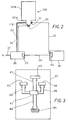
- FIG. 2 With reference to the block diagram of Figure 2 there is illustrated a diagnostic apparatus in accordance with the present invention applied to a vacuum pump 100.
- the vacuum pump that is schematically illustrated in Figure 2 comprises a first portion having a smaller cross section, indicated by the same reference 101a as used in Figure 1 and housing the motor 121 and the lower bearing 122 for supporting the rotatable shaft 123, and a second portion having a larger cross section and indicated by the same reference 101b as used in Figure 1, and housing the gas pumping stages.
- the diagnostic apparatus of Figure 2 comprises a temperature sensor 30, adapted to produce an electrical signal the intensity of which is proportional to the temperature measured on the vacuum pump 100.
- This temperature sensor 30 is preferably located in correspondence with the axial extension 118 of the portion 101a of the casing 101 of the vacuum pump 100.
- a second temperature sensor can be provided for measuring the temperature in another area of the pump body, for example the area of the second bearing located between the pumping stages and the pump motor 121.
- the diagnostic apparatus in accordance with the invention further provides for a vibration transducer 31 such as an accelerometer, a velocimeter, a position sensor or the like, adapted to generate an electric signal having an intensity that is proportional to an acceleration, a speed or a displacement measured in correspondence of the rotatable components of the vacuum pump 100.
- a vibration transducer 31 such as an accelerometer, a velocimeter, a position sensor or the like, adapted to generate an electric signal having an intensity that is proportional to an acceleration, a speed or a displacement measured in correspondence of the rotatable components of the vacuum pump 100.
- such transducer 31 can be a piezoelectric accelerometer, preferably disposed in contact with the body of the vacuum pump 100 at one of its portions housing the support bearings of the rotatable shaft 123.
- the frequency of the induced vibrations substantially corresponds to the rotation frequency
- An accelerometer is a device capable of measuring the acceleration amount of a vibrating surface on which the device is disposed.
- Figure 2 additionally shows a control and feeding unit 20, leads 21 for feeding said control unit 20 through the public power distribution network, and leads 22 for feeding the vacuum pump 100 through said control unit 20.
- the diagnostic apparatus of the present invention further comprises a processing unit 40 receiving the signal from said transducer 31 on the vacuum pump 100, through a lead 33.
- the output signal of said temperature sensor 30 is applied to the control unit 20 through leads 32 and is rendered available as an output signal on a serial communication port of this unit 20.
- control and feeding unit 20 further supplies a plurality of signals related to significant operating parameters of the vacuum pump 100.
- these signals are proportional to the feeding voltage applied to the electric motor, preferably a three-phase A.C. asynchronous motor that drives the vacuum pump 100, such voltage being supplied by said control and feeding unit 20 (WOMO signal), to the current circulating in the electric motor of the vacuum pump 100 (CUMO signal), to the drive frequency of said electric motor (FRMO signal), to the type of the cooling system of the vacuum pump 100 i.e. an air cooled or a water cooled system, (WACO signal), and to the overall operating condition of the vacuum pump, i.e. "normal", "loaded” or at "low speed” (STATUS signal).
- WOMO signal three-phase A.C. asynchronous motor that drives the vacuum pump 100
- CUMO signal current circulating in the electric motor of the vacuum pump 100
- FRMO signal drive frequency of said electric motor
- WACO signal air cooled or a water cooled system
- the above signals are applied through a serial data transmission line 34 to the processing unit 40 that is in turn equiped with a serial communication port 45.
- the processing unit 40 comprises a microprocessor 41, a first memory device 42 storing the control instructions for the microprocessor 41, a second memory device di 43 storing predetermined threshold values of the characteristic parameters of the moving parts of the vacuum pump 100, and a third memory device 44, for periodically storing the values of said characteristic parameters of the moving parts of the vacuum pump 100.
- the microprocessor 41 is connected to the above memory devices 42 to 43 through data transmission "buses", indicated in Figure 3 by the references 46 to 48, respectively.
- Microprocessor 41 is further provided with an additional data transmission "bus" 49 for communicating outside the processing unit 40, through the serial communication port 45 provided on such unit.
- the diagnostic apparatus of the present invention further comprises devices (not shown) for the visual and/or audio warning signals that are activated by a signal generated by the microprocessor 41 upon reaching predetermined pre-alarm or alarm conditions.
- Additional means can be provided for shut off the electric feeding to the vacuum pump upon reaching a predetermined alarm condition.
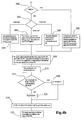
- control logic of the diagnostic method in accordance with the invention is implemented through a sequence of instructions stored in the first memory device 42 for controlling of the microprocessor working.
- step or logic block 200 the microprocessore 41 receives, through the STATUS signal from the control and feeding unit 20, information relating to the working condition of the vacuum pump 100, such as "normal", “loaded” or “low speed” conditions.
- control is returned to the logic block 200 for a further acquisition of the STATUS signal.
- T bs T est + (C p * W p ) + (C b * W b )
- T c T est + [(C p * (W t - W b )] + (C b * W b ).
- the power W b dissipated by the pump bearing(s) and the dimensional constant C b of the bearing(s) are variable but known for a given bearing since they do not depend on the amount of gas (load) sucked by the pump.
- the maximum allowable value is used as room temperature.
- the microprocessor 41 receives data relating to the vibration acceleration of the vacuum pump rotatable components, generated by the accelerometer 31.
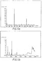
- the data acquisition of the acceleration data is such as to generate two signals ACQSL and ACQSH for frequencies between 0 and 2,000 Hz, and between 0 and 12 kHz, respectively.
- Fig.s 5a and 5b show the acceleration levels in the frequency ranges comprised between 0 and 2,000 Hz, and between 0 and 12 kHz, respectively, for a turbomolecular pump.
- the acceleration data acquisition procedure provides the sampling of the analog signal from the accelerometer 31 at a rate that must be at least twice the maximum frequency of the signal for an accurate recovery of the original signal (Nyquist theorem).
- the acquired signals ACQSL and ACQSH are subjected to a FFT (Fast Fourier Transform) algorithm to obtain the envelope of said signals in the corresponding spectral distribution, arranged in frequency order, thus achieving a signal representative of the distribution of the vibration acceleration as a function of the frequency.
- FFT Fast Fourier Transform
- the method of the invention looks for the peak having the maximum amplitude within said operating range [Ft - 50 Hz, Ft + 50 Hz], and the frequency value corresponding to said peak is associated to the experimental rotation frequency F r of the rotor in the vacuum pump.
- a search is performed - over the spectrum obtained through the FFT processing of the acceleration signals - of the peaks corresponding to the experimental vibration frequencies (ftr) of the rotating components and said peaks are then associated to the corresponding typical theoretical frequencies ftt.
- the above search comprises the following steps.
- an operating range [ftt x - n ⁇ f, ftt x + n ⁇ f] is defined, where
- the logic block 265 After calculating the number of ftts within the operating range, the logic block 265 localizes a new operating range [ftt min , ftt max ], within the first operating range.
- Said second operating range is comprised between the minimum and the maximum ftts that are located within the first operating range [ftt x - n ⁇ f, ftt x + n ⁇ f].
- logic block 275 calculates the number NN of ftts that are present in the extended operating range [x min , x max ] selected in the previous logic block 270.
- Logic block 280 calculates the mean amplitude value of the spectrum within the extended operating range [x min , x max ].
- an auxiliary spectrum is formed where the amplitude values within the range [x min , x max ] that are lower than the mean value calculated by the previous logic block 280 are set equal to said mean value.
- Logic block 290 calculates the number NNP of the peaks in the auxiliary spectrum that are located within the extended operating range [x min , x max ].
- the above disclosed procedure illustrated with reference to logic blocks 280 to 290 aims to cancel the spectrum components deriving from the background noise.
- the NNP detected peaks are associated to the NN amplitudes corresponding to the theoretical frequencies ftts in the considered frequency range, in accordance with the principle of associating each theoretical frequency with the peak detected at the nearest frequency.
- logic block 301 associates to the theoretical frequencies ftts in the extended operating range a frequency that has been detected equal to the theoretical one and has an amplitude equal to the bottom level in the range.
- next logic block 303 assigns to each theoretical frequency in the extended operating range [x min , x max ], the peak detected at the nearest fequency.
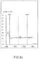
- Figure 6c illustrates an example relating to such situation where the nearest experimental peak (cross) is associated to the single theoretical frequency (dashed line) present in the considered range.
- logic block 305 associates to each ftt the peak detected at the nearest frequency.
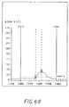
- Figure 6d illustrates an example relating to a situation where NNP ⁇ NN.
- the only experimental peak identified (right cross) is associated with the nearest theoretical frequency (right dashed line) whereas to the remaining theoretical frequency (left dashed line) it is associated the amplitude value corresponding to the bottom (mean) level of the amplitudes (left cross).
- the corresponding associated amplitude is reduced proportionally to the number di ftts to which the same peak has been associated.
- the corresponding amplitude associated to such two ftts will be half of the peak amplitude.
- This second embodiment of the method of the invention is particularly advantageous when using small size pumps on which there are mounted equal bearings having their ftts coincident.
- the amplitude of each peak associated with the ftts is stored so as to generate the following data matrix for the rotor, the lower bearing and the upper bearing.
- Theoretical frequency Detected fr. Peak amplitude F ecc F r A(F r ) f1 or f1 or,r A1(f or,r ) f1 ir f1 rb,r A1(f ir,r ) f1 rb f1 rb,r A1(f rb,r ) f1 c f1 c,r A1(f c,r ) f2 or f2 or,r A2(f or,r ) f2 ir f2 rb,r A2(f ir,r ) f2 rb f2 rb,r A2(f rb,r ) f2 c f2 c,r A2(f c,r
- the amplitudes of the maxima previously associated with the ftts are compared with the reference thresholds contained in the storing device 43 of the processing unity 40.
- Said reference thresholds are determinated on the basis of the spectra obtained for new pumps and used pumps.
- the reference thresholds for the acceleration amplitudes used in the illustrated embodiment were the following: F rot 1.10 m/sec 2 f c upper bearing 0.50 m/sec 2 f c lower bearing 0.34 m/sec 2 ftr comprised between F rot and 8,500 Hz 0.60 m/sec 2 F rot higher than 8,500 Hz 1.20 m/sec 2
- the above thresholds are those for a particular type of pump used in an embodiment, and therefore should be modified to adjust the diagnostic method to pumps of different type by storing suitable values in the storing device 43.
- the calculation of an attention level LEVEL is carried out, when the temperature and vibration safety thresholds have been exceeded by the pump.
- LEVEL ⁇ i [W(i) * FLAG(i)] + W(Temp) *Flag(Temp) where W(i) are the weights assigned to the FLAGs associated with the amplitudes of the vibration spectrum.
- the microprocessor 41 On the basis of the value assumed by the LEVEL signal, at logic block 335 the microprocessor 41 will indicate one of the following operating conditions.
- This condition relates to a normal operating situation that does not require any intervention.
- a second operating condition is indicated when LEVEL ⁇ 3.
- This condition relates to a operating situation that requires a medium-term intervention.
- a third operating condition is indicated when LEVEL>3.
- This condition relates to a operating situation that requires an immediate intervention.
- an alarm level is signalled only when such level is maintained for a given time interval.
- this time interval has been set equal to 60 minutes.
- the parameters relating to the pump working are periodically stored for being subsequentely analyzed and used for modifying the predetermined threshold levels.
- a preliminary analysis step of the vibration spectrum is provided for distinguishing between signals due for example to the presence of two vacuum pumps working one near the other.
- a suitable range is defined containing the two theoretical rotation frequencies. Assuming that F t1 ⁇ F t2 , such range will be, for example, [F t1 - 50 zH, F t2 + 50 zH].
- Figures 7a, 7b and 7c illustrate the spectra relating to a pump rotating at a speed of 680 Hz, an adjacent pump rotating at a speed of 700 Hz as well as the superimposing of the two spectra.
- an alarm level can be defined that is proportional to the difference between the measured amplitude and the theoretical amplitude.
- the diagnostic method of the invention allows to identify - within the vibrational spectrum of the pump - the spectral lines caused by the vibrations of the rotatable components during their rotation and supplies an indication of the pump wear, regardless of environmental disturbances for example those caused by pumps operating nearby, voltage transformers, relais and other sources of vibrations. This has been achieved through an accurate spectral analysis and a combination with further information relating to the working of the vacuum pump but different from the acceleration spectrum, such as the temperature and the current drawn by the electric motor driving the pump.
Landscapes
- Engineering & Computer Science (AREA)
- Mechanical Engineering (AREA)
- General Engineering & Computer Science (AREA)
- Non-Positive Displacement Air Blowers (AREA)
- Compressors, Vaccum Pumps And Other Relevant Systems (AREA)
- Control Of Positive-Displacement Pumps (AREA)
Applications Claiming Priority (2)
| Application Number | Priority Date | Filing Date | Title |
|---|---|---|---|
| IT96TO001091 IT1289811B1 (it) | 1996-12-27 | 1996-12-27 | Metodo ed apparato di diagnosi per pompa da vuoto. |
| ITTO961091 | 1996-12-27 |
Publications (3)
| Publication Number | Publication Date |
|---|---|
| EP0851127A2 true EP0851127A2 (fr) | 1998-07-01 |
| EP0851127A3 EP0851127A3 (fr) | 1999-06-16 |
| EP0851127B1 EP0851127B1 (fr) | 2003-02-05 |
Family
ID=11415164
Family Applications (1)
| Application Number | Title | Priority Date | Filing Date |
|---|---|---|---|
| EP19970202185 Revoked EP0851127B1 (fr) | 1996-12-27 | 1997-07-12 | Procédé et dispositif de diagnostic pour pompes à vide |
Country Status (3)
| Country | Link |
|---|---|
| EP (1) | EP0851127B1 (fr) |
| DE (1) | DE69718889T2 (fr) |
| IT (1) | IT1289811B1 (fr) |
Cited By (11)
| Publication number | Priority date | Publication date | Assignee | Title |
|---|---|---|---|---|
| WO2008012150A1 (fr) | 2006-07-26 | 2008-01-31 | Oerlikon Leybold Vacuum Gmbh | Procédé permettant de déterminer une indication de l'état d'une pompe tubomoléculaire et pompe turbomoléculaire |
| GB2507500A (en) * | 2012-10-30 | 2014-05-07 | Edwards Ltd | Vacuum pump with contact detection for back-up bearing |
| WO2014068277A1 (fr) * | 2012-10-30 | 2014-05-08 | Edwards Limited | Pompe à vide |
| CN106321464A (zh) * | 2015-07-01 | 2017-01-11 | 现代自动车株式会社 | 用于诊断电油泵转子的磨损的方法 |
| US9828992B2 (en) | 2015-07-09 | 2017-11-28 | Hamilton Sundstrand Corporation | Vane pumps with vane wear detection |
| GB2551337A (en) * | 2016-06-13 | 2017-12-20 | Edwards Ltd | Pump assembly, method and computer program |
| EP2314877B1 (fr) * | 2008-07-14 | 2018-08-22 | Edwards Japan Limited | Pompe à vide |
| EP3557072A1 (fr) * | 2019-02-27 | 2019-10-23 | Pfeiffer Vacuum Gmbh | Surveillance d'un dispositif de palier d'une pompe à vide |
| JP2019214993A (ja) * | 2018-06-14 | 2019-12-19 | 株式会社島津製作所 | 真空ポンプおよび診断システム |
| EP3933355A1 (fr) | 2020-06-30 | 2022-01-05 | Alfa Laval Corporate AB | Procédé de surveillance de condition de fonctionnement d'un équipement rotatif |
| CN119333396A (zh) * | 2024-11-29 | 2025-01-21 | 南京真空泵厂有限公司 | 一种基于数据分析的螺杆真空泵故障监测系统及方法 |
Families Citing this family (3)
| Publication number | Priority date | Publication date | Assignee | Title |
|---|---|---|---|---|
| CN102425563B (zh) * | 2011-12-08 | 2014-03-12 | 北京中科科仪股份有限公司 | 同步抑制磁悬浮分子泵转子次临界振动的方法和系统 |
| DE102013223020A1 (de) * | 2013-11-12 | 2015-05-13 | Oerlikon Leybold Vacuum Gmbh | Verfahren zum Betreiben einer Vakuumpumpe |
| FR3117435B1 (fr) | 2020-12-16 | 2022-10-28 | Psa Automobiles Sa | Procede de diagnostic d’une defaillance de generation de vide dans un amplificateur de freinage |
Citations (1)
| Publication number | Priority date | Publication date | Assignee | Title |
|---|---|---|---|---|
| EP0445855A1 (fr) | 1990-03-09 | 1991-09-11 | VARIAN S.p.A. | Pompe turbomoléculaire améliorée |
Family Cites Families (2)
| Publication number | Priority date | Publication date | Assignee | Title |
|---|---|---|---|---|
| EP0654163B1 (fr) * | 1992-08-10 | 2000-07-26 | Dow Deutschland Inc. | Procede et dispositif permettant de surveiller l'excitation vibratoire d'un compresseur axial |
| DE19511430A1 (de) * | 1995-03-29 | 1996-10-02 | Leybold Ag | Umwälzgebläse, Vakuumpumpe oder dergleichen |
-
1996
- 1996-12-27 IT IT96TO001091 patent/IT1289811B1/it active IP Right Grant
-
1997
- 1997-07-12 DE DE1997618889 patent/DE69718889T2/de not_active Expired - Lifetime
- 1997-07-12 EP EP19970202185 patent/EP0851127B1/fr not_active Revoked
Patent Citations (1)
| Publication number | Priority date | Publication date | Assignee | Title |
|---|---|---|---|---|
| EP0445855A1 (fr) | 1990-03-09 | 1991-09-11 | VARIAN S.p.A. | Pompe turbomoléculaire améliorée |
Cited By (26)
| Publication number | Priority date | Publication date | Assignee | Title |
|---|---|---|---|---|
| WO2008012150A1 (fr) | 2006-07-26 | 2008-01-31 | Oerlikon Leybold Vacuum Gmbh | Procédé permettant de déterminer une indication de l'état d'une pompe tubomoléculaire et pompe turbomoléculaire |
| EP2314877B1 (fr) * | 2008-07-14 | 2018-08-22 | Edwards Japan Limited | Pompe à vide |
| US9822788B2 (en) | 2012-10-30 | 2017-11-21 | Edwards Limited | Vacuum pump with back-up bearing contact sensor |
| WO2014068277A1 (fr) * | 2012-10-30 | 2014-05-08 | Edwards Limited | Pompe à vide |
| GB2507500B (en) * | 2012-10-30 | 2015-06-17 | Edwards Ltd | Vacuum pump |
| CN104781558A (zh) * | 2012-10-30 | 2015-07-15 | 爱德华兹有限公司 | 真空泵 |
| WO2014068276A1 (fr) * | 2012-10-30 | 2014-05-08 | Edwards Limited | Pompe à vide dotée d'un capteur de contact à palier amortisseur |
| GB2507500A (en) * | 2012-10-30 | 2014-05-07 | Edwards Ltd | Vacuum pump with contact detection for back-up bearing |
| US10024328B2 (en) | 2012-10-30 | 2018-07-17 | Edwards Limited | Vacuum pump |
| CN106321464A (zh) * | 2015-07-01 | 2017-01-11 | 现代自动车株式会社 | 用于诊断电油泵转子的磨损的方法 |
| KR20170005226A (ko) | 2015-07-01 | 2017-01-12 | 현대자동차주식회사 | Eop 로터 마모진단 방법 |
| US9689773B2 (en) | 2015-07-01 | 2017-06-27 | Hyundai Motor Company | Method for diagnosing abrasion of electric oil pump rotor |
| CN106321464B (zh) * | 2015-07-01 | 2019-09-20 | 现代自动车株式会社 | 用于诊断电油泵转子的磨损的方法 |
| US9828992B2 (en) | 2015-07-09 | 2017-11-28 | Hamilton Sundstrand Corporation | Vane pumps with vane wear detection |
| WO2017216514A1 (fr) * | 2016-06-13 | 2017-12-21 | Edwards Limited | Ensemble pompe, procédé et programme d'ordinateur |
| CN109563840A (zh) * | 2016-06-13 | 2019-04-02 | 爱德华兹有限公司 | 泵组件、方法和计算机程序 |
| GB2551337A (en) * | 2016-06-13 | 2017-12-20 | Edwards Ltd | Pump assembly, method and computer program |
| CN109563840B (zh) * | 2016-06-13 | 2021-08-24 | 爱德华兹有限公司 | 泵组件和方法 |
| TWI751170B (zh) * | 2016-06-13 | 2022-01-01 | 英商愛德華有限公司 | 泵總成、分析自經安裝於一泵上之一加速度計接收之資料的方法及電腦程式 |
| JP2019214993A (ja) * | 2018-06-14 | 2019-12-19 | 株式会社島津製作所 | 真空ポンプおよび診断システム |
| JP7006520B2 (ja) | 2018-06-14 | 2022-01-24 | 株式会社島津製作所 | 真空ポンプおよび診断システム |
| US11359636B2 (en) | 2018-06-14 | 2022-06-14 | Shimadzu Corporation | Vacuum pump and diagnosis system |
| EP3557072A1 (fr) * | 2019-02-27 | 2019-10-23 | Pfeiffer Vacuum Gmbh | Surveillance d'un dispositif de palier d'une pompe à vide |
| EP3933355A1 (fr) | 2020-06-30 | 2022-01-05 | Alfa Laval Corporate AB | Procédé de surveillance de condition de fonctionnement d'un équipement rotatif |
| WO2022002548A1 (fr) | 2020-06-30 | 2022-01-06 | Alfa Laval Corporate Ab | Procédé de surveillance de l'état de fonctionnement d'un équipement rotatif |
| CN119333396A (zh) * | 2024-11-29 | 2025-01-21 | 南京真空泵厂有限公司 | 一种基于数据分析的螺杆真空泵故障监测系统及方法 |
Also Published As
| Publication number | Publication date |
|---|---|
| ITTO961091A1 (it) | 1998-06-27 |
| EP0851127B1 (fr) | 2003-02-05 |
| IT1289811B1 (it) | 1998-10-16 |
| EP0851127A3 (fr) | 1999-06-16 |
| DE69718889D1 (de) | 2003-03-13 |
| DE69718889T2 (de) | 2003-10-30 |
Similar Documents
| Publication | Publication Date | Title |
|---|---|---|
| EP0851127B1 (fr) | Procédé et dispositif de diagnostic pour pompes à vide | |
| US6065345A (en) | Method for monitoring the condition of a mechanical seal | |
| US5285457A (en) | Apparatus for detecting an abnormal bearing condition of a blower utilized for gas laser equipment | |
| CN110608177B (zh) | 真空泵及诊断系统 | |
| US5767780A (en) | Detector for flow abnormalities in gaseous diffusion plant compressors | |
| CN101273385B (zh) | 旋转机器中的或与其相关的改进 | |
| CN112161806A (zh) | 风机的故障监测方法和故障监测装置 | |
| US20120330578A1 (en) | Severity analysis apparatus and method for shafts of rotating machinery | |
| KR102068077B1 (ko) | 복합 신호를 이용한 회전기계설비 진단장치 | |
| JP7160978B2 (ja) | 真空ポンプ及び真空ポンプを監視する方法 | |
| EP1556675A4 (fr) | Procede et systeme visant a determiner la cavitation d'une pompe et a evaluer la degradation des joints d'etancheite de celle-ci | |
| CN119000071A (zh) | 一种滚动轴承故障诊断方法及系统 | |
| JP2011053144A (ja) | 空冷式真空ポンプの軸受寿命予知方法及び軸受寿命予知装置 | |
| JP2001330510A (ja) | 回転機械の異常診断方法 | |
| KR102343985B1 (ko) | 보스 일체형 임펠러가 구비된 송풍 시스템 | |
| JPWO2018096640A1 (ja) | 電力変換装置 | |
| JP7239510B2 (ja) | 真空ポンプ | |
| US7580802B2 (en) | Method of determining condition of a turbine blade, and utilizing the collected information for estimation of the lifetime of the blade | |
| US20240118170A1 (en) | Vibration monitoring device, turbocharger, and vibration monitoring method | |
| JP2024077462A (ja) | 点検装置、および音源位置の推定方法 | |
| WO2022243682A1 (fr) | Système et procédé de surveillance de pompe | |
| CN209910708U (zh) | 绞吸船的状态监测系统 | |
| JPS628023A (ja) | 回転機械の診断方法 | |
| JP7495919B2 (ja) | 摩耗検知システム及び摩耗検知方法 | |
| JPH0743278B2 (ja) | 回転機械の診断装置 |
Legal Events
| Date | Code | Title | Description |
|---|---|---|---|
| PUAI | Public reference made under article 153(3) epc to a published international application that has entered the european phase |
Free format text: ORIGINAL CODE: 0009012 |
|
| AK | Designated contracting states |
Kind code of ref document: A2 Designated state(s): DE FR GB IT |
|
| AX | Request for extension of the european patent |
Free format text: AL;LT;LV;RO;SI |
|
| PUAL | Search report despatched |
Free format text: ORIGINAL CODE: 0009013 |
|
| AK | Designated contracting states |
Kind code of ref document: A3 Designated state(s): AT BE CH DE DK ES FI FR GB GR IE IT LI LU MC NL PT SE |
|
| AX | Request for extension of the european patent |
Free format text: AL;LT;LV;RO;SI |
|
| RIC1 | Information provided on ipc code assigned before grant |
Free format text: 6F 04D 27/02 A, 6F 04D 19/04 B, 6F 04D 27/00 B |
|
| 17P | Request for examination filed |
Effective date: 19990719 |
|
| AKX | Designation fees paid |
Free format text: DE FR GB IT |
|
| GRAG | Despatch of communication of intention to grant |
Free format text: ORIGINAL CODE: EPIDOS AGRA |
|
| 17Q | First examination report despatched |
Effective date: 20020529 |
|
| GRAG | Despatch of communication of intention to grant |
Free format text: ORIGINAL CODE: EPIDOS AGRA |
|
| GRAH | Despatch of communication of intention to grant a patent |
Free format text: ORIGINAL CODE: EPIDOS IGRA |
|
| GRAH | Despatch of communication of intention to grant a patent |
Free format text: ORIGINAL CODE: EPIDOS IGRA |
|
| GRAA | (expected) grant |
Free format text: ORIGINAL CODE: 0009210 |
|
| AK | Designated contracting states |
Designated state(s): DE FR GB IT |
|
| REG | Reference to a national code |
Ref country code: GB Ref legal event code: FG4D |
|
| REF | Corresponds to: |
Ref document number: 69718889 Country of ref document: DE Date of ref document: 20030313 Kind code of ref document: P |
|
| ET | Fr: translation filed | ||
| PLBQ | Unpublished change to opponent data |
Free format text: ORIGINAL CODE: EPIDOS OPPO |
|
| PLBI | Opposition filed |
Free format text: ORIGINAL CODE: 0009260 |
|
| PLBQ | Unpublished change to opponent data |
Free format text: ORIGINAL CODE: EPIDOS OPPO |
|
| PLBI | Opposition filed |
Free format text: ORIGINAL CODE: 0009260 |
|
| PLAX | Notice of opposition and request to file observation + time limit sent |
Free format text: ORIGINAL CODE: EPIDOSNOBS2 |
|
| 26 | Opposition filed |
Opponent name: LEYBOLD VAKUUM GMBH Effective date: 20031015 |
|
| 26 | Opposition filed |
Opponent name: PFEIFFER VACUUM GMBH Effective date: 20031029 Opponent name: LEYBOLD VAKUUM GMBH Effective date: 20031015 |
|
| PLBB | Reply of patent proprietor to notice(s) of opposition received |
Free format text: ORIGINAL CODE: EPIDOSNOBS3 |
|
| PLAB | Opposition data, opponent's data or that of the opponent's representative modified |
Free format text: ORIGINAL CODE: 0009299OPPO |
|
| R26 | Opposition filed (corrected) |
Opponent name: PFEIFFER VACUUM GMBH Effective date: 20031029 Opponent name: LEYBOLD VACUUM GMBH Effective date: 20031015 |
|
| PGFP | Annual fee paid to national office [announced via postgrant information from national office to epo] |
Ref country code: IT Payment date: 20100728 Year of fee payment: 14 Ref country code: FR Payment date: 20100805 Year of fee payment: 14 |
|
| PGFP | Annual fee paid to national office [announced via postgrant information from national office to epo] |
Ref country code: GB Payment date: 20100726 Year of fee payment: 14 |
|
| REG | Reference to a national code |
Ref country code: DE Ref legal event code: R082 Ref document number: 69718889 Country of ref document: DE Representative=s name: BARTH, DANIEL, DIPL.-ING., DE Effective date: 20111124 Ref country code: DE Ref legal event code: R082 Ref document number: 69718889 Country of ref document: DE Representative=s name: DILG HAEUSLER SCHINDELMANN PATENTANWALTSGESELL, DE Effective date: 20111124 Ref country code: DE Ref legal event code: R081 Ref document number: 69718889 Country of ref document: DE Owner name: AGILENT TECHNOLOGIES, INC., SANTA CLARA, US Free format text: FORMER OWNER: VARIAN S.P.A., LEINI, TURIN/TORINO, IT Effective date: 20111124 Ref country code: DE Ref legal event code: R081 Ref document number: 69718889 Country of ref document: DE Owner name: AGILENT TECHNOLOGIES, INC., US Free format text: FORMER OWNER: VARIAN S.P.A., LEINI, IT Effective date: 20111124 Ref country code: DE Ref legal event code: R081 Ref document number: 69718889 Country of ref document: DE Owner name: AGILENT TECHNOLOGIES ITALIA S.P.A., IT Free format text: FORMER OWNER: VARIAN S.P.A., LEINI, IT Effective date: 20111124 |
|
| GBPC | Gb: european patent ceased through non-payment of renewal fee |
Effective date: 20110712 |
|
| REG | Reference to a national code |
Ref country code: FR Ref legal event code: ST Effective date: 20120330 |
|
| PG25 | Lapsed in a contracting state [announced via postgrant information from national office to epo] |
Ref country code: FR Free format text: LAPSE BECAUSE OF NON-PAYMENT OF DUE FEES Effective date: 20110801 |
|
| PG25 | Lapsed in a contracting state [announced via postgrant information from national office to epo] |
Ref country code: IT Free format text: LAPSE BECAUSE OF NON-PAYMENT OF DUE FEES Effective date: 20110712 |
|
| RAP2 | Party data changed (patent owner data changed or rights of a patent transferred) |
Owner name: AGILENT TECHNOLOGIES ITALIA S.P.A. |
|
| PG25 | Lapsed in a contracting state [announced via postgrant information from national office to epo] |
Ref country code: GB Free format text: LAPSE BECAUSE OF NON-PAYMENT OF DUE FEES Effective date: 20110712 |
|
| RAP2 | Party data changed (patent owner data changed or rights of a patent transferred) |
Owner name: AGILENT TECHNOLOGIES, INC. |
|
| PLAB | Opposition data, opponent's data or that of the opponent's representative modified |
Free format text: ORIGINAL CODE: 0009299OPPO |
|
| R26 | Opposition filed (corrected) |
Opponent name: PFEIFFER VACUUM GMBH Effective date: 20031029 Opponent name: OERLIKON LEYBOLD VACUUM GMBH Effective date: 20031015 |
|
| PGFP | Annual fee paid to national office [announced via postgrant information from national office to epo] |
Ref country code: DE Payment date: 20120704 Year of fee payment: 16 |
|
| REG | Reference to a national code |
Ref country code: DE Ref legal event code: R082 Ref document number: 69718889 Country of ref document: DE Representative=s name: BARTH, DANIEL, DIPL.-ING., DE Ref country code: DE Ref legal event code: R082 Ref document number: 69718889 Country of ref document: DE Representative=s name: DILG HAEUSLER SCHINDELMANN PATENTANWALTSGESELL, DE |
|
| REG | Reference to a national code |
Ref country code: DE Ref legal event code: R082 Ref document number: 69718889 Country of ref document: DE Representative=s name: DILG HAEUSLER SCHINDELMANN PATENTANWALTSGESELL, DE Ref country code: DE Ref legal event code: R082 Ref document number: 69718889 Country of ref document: DE Representative=s name: BARTH, DANIEL, DIPL.-ING., DE |
|
| REG | Reference to a national code |
Ref country code: DE Ref legal event code: R082 Ref document number: 69718889 Country of ref document: DE Representative=s name: DILG HAEUSLER SCHINDELMANN PATENTANWALTSGESELL, DE |
|
| REG | Reference to a national code |
Ref country code: DE Ref legal event code: R082 Ref document number: 69718889 Country of ref document: DE Representative=s name: DILG HAEUSLER SCHINDELMANN PATENTANWALTSGESELL, DE |
|
| REG | Reference to a national code |
Ref country code: DE Ref legal event code: R082 Ref document number: 69718889 Country of ref document: DE Representative=s name: DILG HAEUSLER SCHINDELMANN PATENTANWALTSGESELL, DE Effective date: 20130304 Ref country code: DE Ref legal event code: R082 Ref document number: 69718889 Country of ref document: DE Representative=s name: DILG HAEUSLER SCHINDELMANN PATENTANWALTSGESELL, DE Effective date: 20130521 Ref country code: DE Ref legal event code: R082 Ref document number: 69718889 Country of ref document: DE Representative=s name: DILG HAEUSLER SCHINDELMANN PATENTANWALTSGESELL, DE Effective date: 20130312 Ref country code: DE Ref legal event code: R082 Ref document number: 69718889 Country of ref document: DE Representative=s name: DILG HAEUSLER SCHINDELMANN PATENTANWALTSGESELL, DE Effective date: 20130320 Ref country code: DE Ref legal event code: R081 Ref document number: 69718889 Country of ref document: DE Owner name: AGILENT TECHNOLOGIES, INC., SANTA CLARA, US Free format text: FORMER OWNER: AGILENT TECHNOLOGIES ITALIA S.P.A., CERNUSCO SUL NAVIGLIO, MILANO, IT Effective date: 20130521 Ref country code: DE Ref legal event code: R081 Ref document number: 69718889 Country of ref document: DE Owner name: AGILENT TECHNOLOGIES, INC., US Free format text: FORMER OWNER: AGILENT TECHNOLOGIES ITALIA S.P.A., CERNUSCO SUL NAVIGLIO, IT Effective date: 20130521 |
|
| RDAF | Communication despatched that patent is revoked |
Free format text: ORIGINAL CODE: EPIDOSNREV1 |
|
| REG | Reference to a national code |
Ref country code: DE Ref legal event code: R119 Ref document number: 69718889 Country of ref document: DE Effective date: 20140201 |
|
| PG25 | Lapsed in a contracting state [announced via postgrant information from national office to epo] |
Ref country code: DE Free format text: LAPSE BECAUSE OF NON-PAYMENT OF DUE FEES Effective date: 20140201 |
|
| RDAG | Patent revoked |
Free format text: ORIGINAL CODE: 0009271 |
|
| STAA | Information on the status of an ep patent application or granted ep patent |
Free format text: STATUS: PATENT REVOKED |
|
| 27W | Patent revoked |
Effective date: 20140224 |