EP2319430B1 - Appareil d'embolisation vasculaire et procédé pour sa fabrication - Google Patents
Appareil d'embolisation vasculaire et procédé pour sa fabrication Download PDFInfo
- Publication number
- EP2319430B1 EP2319430B1 EP10183747.4A EP10183747A EP2319430B1 EP 2319430 B1 EP2319430 B1 EP 2319430B1 EP 10183747 A EP10183747 A EP 10183747A EP 2319430 B1 EP2319430 B1 EP 2319430B1
- Authority
- EP
- European Patent Office
- Prior art keywords
- carrier
- polymer
- embolizing
- hydrogel
- embolizing element
- Prior art date
- Legal status (The legal status is an assumption and is not a legal conclusion. Google has not performed a legal analysis and makes no representation as to the accuracy of the status listed.)
- Expired - Lifetime
Links
- 238000000034 method Methods 0.000 title claims abstract description 121
- 230000010102 embolization Effects 0.000 title claims abstract description 119
- 230000002792 vascular Effects 0.000 title claims description 72
- 238000004519 manufacturing process Methods 0.000 title description 4
- 239000000017 hydrogel Substances 0.000 claims abstract description 97
- 239000003814 drug Substances 0.000 claims abstract description 21
- 230000004044 response Effects 0.000 claims abstract description 19
- 229940124597 therapeutic agent Drugs 0.000 claims abstract description 17
- 229920000642 polymer Polymers 0.000 claims description 108
- 230000036571 hydration Effects 0.000 claims description 28
- 238000006703 hydration reaction Methods 0.000 claims description 28
- 229910052751 metal Inorganic materials 0.000 claims description 12
- 239000002184 metal Substances 0.000 claims description 12
- 239000002609 medium Substances 0.000 claims description 11
- 239000002253 acid Substances 0.000 claims description 7
- 239000012736 aqueous medium Substances 0.000 claims description 6
- 238000010438 heat treatment Methods 0.000 claims description 5
- 238000005538 encapsulation Methods 0.000 claims description 4
- 229920005594 polymer fiber Polymers 0.000 claims description 3
- PXHVJJICTQNCMI-UHFFFAOYSA-N Nickel Chemical compound [Ni] PXHVJJICTQNCMI-UHFFFAOYSA-N 0.000 abstract description 10
- 230000007613 environmental effect Effects 0.000 abstract description 7
- 238000000465 moulding Methods 0.000 abstract description 6
- 239000006261 foam material Substances 0.000 abstract description 5
- 230000008859 change Effects 0.000 abstract description 4
- 229910000990 Ni alloy Inorganic materials 0.000 abstract description 3
- 229910001069 Ti alloy Inorganic materials 0.000 abstract description 3
- 206010002329 Aneurysm Diseases 0.000 description 53
- 239000000463 material Substances 0.000 description 35
- BASFCYQUMIYNBI-UHFFFAOYSA-N platinum Chemical compound [Pt] BASFCYQUMIYNBI-UHFFFAOYSA-N 0.000 description 31
- 239000000178 monomer Substances 0.000 description 30
- 239000000243 solution Substances 0.000 description 30
- XLYOFNOQVPJJNP-UHFFFAOYSA-N water Substances O XLYOFNOQVPJJNP-UHFFFAOYSA-N 0.000 description 18
- 230000003073 embolic effect Effects 0.000 description 15
- FAPWRFPIFSIZLT-UHFFFAOYSA-M Sodium chloride Chemical compound [Na+].[Cl-] FAPWRFPIFSIZLT-UHFFFAOYSA-M 0.000 description 14
- 210000004369 blood Anatomy 0.000 description 13
- 239000008280 blood Substances 0.000 description 13
- 229920001477 hydrophilic polymer Polymers 0.000 description 13
- 239000003795 chemical substances by application Substances 0.000 description 11
- 239000003431 cross linking reagent Substances 0.000 description 11
- 239000007788 liquid Substances 0.000 description 11
- 229910052697 platinum Inorganic materials 0.000 description 11
- 239000000203 mixture Substances 0.000 description 10
- 210000003739 neck Anatomy 0.000 description 10
- 230000036961 partial effect Effects 0.000 description 10
- 239000004372 Polyvinyl alcohol Substances 0.000 description 9
- 229920002451 polyvinyl alcohol Polymers 0.000 description 9
- 230000008569 process Effects 0.000 description 9
- 239000002904 solvent Substances 0.000 description 9
- IAZDPXIOMUYVGZ-UHFFFAOYSA-N Dimethylsulphoxide Chemical compound CS(C)=O IAZDPXIOMUYVGZ-UHFFFAOYSA-N 0.000 description 8
- 239000006260 foam Substances 0.000 description 8
- 210000004204 blood vessel Anatomy 0.000 description 7
- -1 e.g. Substances 0.000 description 7
- 239000012530 fluid Substances 0.000 description 7
- 239000007943 implant Substances 0.000 description 7
- 239000011780 sodium chloride Substances 0.000 description 7
- LFQSCWFLJHTTHZ-UHFFFAOYSA-N Ethanol Chemical compound CCO LFQSCWFLJHTTHZ-UHFFFAOYSA-N 0.000 description 6
- 150000001412 amines Chemical class 0.000 description 6
- 230000008901 benefit Effects 0.000 description 6
- 238000009472 formulation Methods 0.000 description 6
- 230000006870 function Effects 0.000 description 6
- 238000011065 in-situ storage Methods 0.000 description 6
- 238000011534 incubation Methods 0.000 description 6
- 229910001000 nickel titanium Inorganic materials 0.000 description 6
- HLXZNVUGXRDIFK-UHFFFAOYSA-N nickel titanium Chemical compound [Ti].[Ti].[Ti].[Ti].[Ti].[Ti].[Ti].[Ti].[Ti].[Ti].[Ti].[Ni].[Ni].[Ni].[Ni].[Ni].[Ni].[Ni].[Ni].[Ni].[Ni].[Ni].[Ni].[Ni].[Ni] HLXZNVUGXRDIFK-UHFFFAOYSA-N 0.000 description 6
- 239000002245 particle Substances 0.000 description 6
- 239000007787 solid Substances 0.000 description 6
- 125000002843 carboxylic acid group Chemical group 0.000 description 5
- 235000019441 ethanol Nutrition 0.000 description 5
- 239000000835 fiber Substances 0.000 description 5
- 238000002347 injection Methods 0.000 description 5
- 239000007924 injection Substances 0.000 description 5
- 230000004048 modification Effects 0.000 description 5
- 238000012986 modification Methods 0.000 description 5
- 229920003229 poly(methyl methacrylate) Polymers 0.000 description 5
- 239000004926 polymethyl methacrylate Substances 0.000 description 5
- 125000006850 spacer group Chemical group 0.000 description 5
- 238000005406 washing Methods 0.000 description 5
- NIXOWILDQLNWCW-UHFFFAOYSA-N 2-Propenoic acid Natural products OC(=O)C=C NIXOWILDQLNWCW-UHFFFAOYSA-N 0.000 description 4
- 125000003277 amino group Chemical group 0.000 description 4
- 238000013459 approach Methods 0.000 description 4
- TZCXTZWJZNENPQ-UHFFFAOYSA-L barium sulfate Chemical compound [Ba+2].[O-]S([O-])(=O)=O TZCXTZWJZNENPQ-UHFFFAOYSA-L 0.000 description 4
- 150000001735 carboxylic acids Chemical class 0.000 description 4
- 230000007547 defect Effects 0.000 description 4
- 230000018044 dehydration Effects 0.000 description 4
- 238000006297 dehydration reaction Methods 0.000 description 4
- 229940079593 drug Drugs 0.000 description 4
- 239000003999 initiator Substances 0.000 description 4
- 230000007246 mechanism Effects 0.000 description 4
- 238000013508 migration Methods 0.000 description 4
- 239000008188 pellet Substances 0.000 description 4
- 210000002381 plasma Anatomy 0.000 description 4
- 229920001343 polytetrafluoroethylene Polymers 0.000 description 4
- 239000004810 polytetrafluoroethylene Substances 0.000 description 4
- 230000002028 premature Effects 0.000 description 4
- 230000000717 retained effect Effects 0.000 description 4
- WFKWXMTUELFFGS-UHFFFAOYSA-N tungsten Chemical compound [W] WFKWXMTUELFFGS-UHFFFAOYSA-N 0.000 description 4
- 239000011800 void material Substances 0.000 description 4
- WOBHKFSMXKNTIM-UHFFFAOYSA-N Hydroxyethyl methacrylate Chemical compound CC(=C)C(=O)OCCO WOBHKFSMXKNTIM-UHFFFAOYSA-N 0.000 description 3
- 229910001260 Pt alloy Inorganic materials 0.000 description 3
- CZMRCDWAGMRECN-UGDNZRGBSA-N Sucrose Chemical compound O[C@H]1[C@H](O)[C@@H](CO)O[C@@]1(CO)O[C@@H]1[C@H](O)[C@@H](O)[C@H](O)[C@@H](CO)O1 CZMRCDWAGMRECN-UGDNZRGBSA-N 0.000 description 3
- 229930006000 Sucrose Natural products 0.000 description 3
- 208000007536 Thrombosis Diseases 0.000 description 3
- 229910001080 W alloy Inorganic materials 0.000 description 3
- 239000000560 biocompatible material Substances 0.000 description 3
- 229920000249 biocompatible polymer Polymers 0.000 description 3
- 210000000601 blood cell Anatomy 0.000 description 3
- 230000001413 cellular effect Effects 0.000 description 3
- 239000011248 coating agent Substances 0.000 description 3
- 238000000576 coating method Methods 0.000 description 3
- 239000000470 constituent Substances 0.000 description 3
- 238000004132 cross linking Methods 0.000 description 3
- 238000001035 drying Methods 0.000 description 3
- 125000000524 functional group Chemical group 0.000 description 3
- 230000007062 hydrolysis Effects 0.000 description 3
- 238000006460 hydrolysis reaction Methods 0.000 description 3
- 238000002513 implantation Methods 0.000 description 3
- 238000010348 incorporation Methods 0.000 description 3
- 230000014759 maintenance of location Effects 0.000 description 3
- 239000011159 matrix material Substances 0.000 description 3
- 238000002483 medication Methods 0.000 description 3
- 229910001092 metal group alloy Inorganic materials 0.000 description 3
- 230000005012 migration Effects 0.000 description 3
- 238000004806 packaging method and process Methods 0.000 description 3
- 229920002338 polyhydroxyethylmethacrylate Polymers 0.000 description 3
- 239000011148 porous material Substances 0.000 description 3
- 230000000452 restraining effect Effects 0.000 description 3
- 229910000679 solder Inorganic materials 0.000 description 3
- 239000005720 sucrose Substances 0.000 description 3
- 230000002885 thrombogenetic effect Effects 0.000 description 3
- 210000001519 tissue Anatomy 0.000 description 3
- 238000011282 treatment Methods 0.000 description 3
- 229910052721 tungsten Inorganic materials 0.000 description 3
- 239000010937 tungsten Substances 0.000 description 3
- 238000012800 visualization Methods 0.000 description 3
- 239000002699 waste material Substances 0.000 description 3
- SMZOUWXMTYCWNB-UHFFFAOYSA-N 2-(2-methoxy-5-methylphenyl)ethanamine Chemical compound COC1=CC=C(C)C=C1CCN SMZOUWXMTYCWNB-UHFFFAOYSA-N 0.000 description 2
- 206010028980 Neoplasm Diseases 0.000 description 2
- 239000004677 Nylon Substances 0.000 description 2
- 208000008883 Patent Foramen Ovale Diseases 0.000 description 2
- WCUXLLCKKVVCTQ-UHFFFAOYSA-M Potassium chloride Chemical compound [Cl-].[K+] WCUXLLCKKVVCTQ-UHFFFAOYSA-M 0.000 description 2
- UIIMBOGNXHQVGW-UHFFFAOYSA-M Sodium bicarbonate Chemical compound [Na+].OC([O-])=O UIIMBOGNXHQVGW-UHFFFAOYSA-M 0.000 description 2
- RTAQQCXQSZGOHL-UHFFFAOYSA-N Titanium Chemical compound [Ti] RTAQQCXQSZGOHL-UHFFFAOYSA-N 0.000 description 2
- 150000007513 acids Chemical class 0.000 description 2
- 239000000654 additive Substances 0.000 description 2
- 239000000853 adhesive Substances 0.000 description 2
- 230000001070 adhesive effect Effects 0.000 description 2
- 150000001336 alkenes Chemical class 0.000 description 2
- ROOXNKNUYICQNP-UHFFFAOYSA-N ammonium persulfate Chemical compound [NH4+].[NH4+].[O-]S(=O)(=O)OOS([O-])(=O)=O ROOXNKNUYICQNP-UHFFFAOYSA-N 0.000 description 2
- 208000013914 atrial heart septal defect Diseases 0.000 description 2
- 210000001124 body fluid Anatomy 0.000 description 2
- 239000010839 body fluid Substances 0.000 description 2
- 230000000747 cardiac effect Effects 0.000 description 2
- 238000010276 construction Methods 0.000 description 2
- 229920001577 copolymer Polymers 0.000 description 2
- 239000013078 crystal Substances 0.000 description 2
- 230000005595 deprotonation Effects 0.000 description 2
- 238000010537 deprotonation reaction Methods 0.000 description 2
- 239000007884 disintegrant Substances 0.000 description 2
- 230000000694 effects Effects 0.000 description 2
- 230000002255 enzymatic effect Effects 0.000 description 2
- 239000004872 foam stabilizing agent Substances 0.000 description 2
- 239000000499 gel Substances 0.000 description 2
- PCHJSUWPFVWCPO-UHFFFAOYSA-N gold Chemical compound [Au] PCHJSUWPFVWCPO-UHFFFAOYSA-N 0.000 description 2
- 229910052737 gold Inorganic materials 0.000 description 2
- 239000010931 gold Substances 0.000 description 2
- 239000003102 growth factor Substances 0.000 description 2
- 238000003384 imaging method Methods 0.000 description 2
- 239000012535 impurity Substances 0.000 description 2
- 238000003780 insertion Methods 0.000 description 2
- 230000037431 insertion Effects 0.000 description 2
- 238000009434 installation Methods 0.000 description 2
- 210000005248 left atrial appendage Anatomy 0.000 description 2
- 239000004005 microsphere Substances 0.000 description 2
- 229910052759 nickel Inorganic materials 0.000 description 2
- 229920001778 nylon Polymers 0.000 description 2
- JRZJOMJEPLMPRA-UHFFFAOYSA-N olefin Natural products CCCCCCCC=C JRZJOMJEPLMPRA-UHFFFAOYSA-N 0.000 description 2
- 210000003101 oviduct Anatomy 0.000 description 2
- 238000007254 oxidation reaction Methods 0.000 description 2
- 208000003278 patent ductus arteriosus Diseases 0.000 description 2
- 230000000704 physical effect Effects 0.000 description 2
- 229920000728 polyester Polymers 0.000 description 2
- 239000003505 polymerization initiator Substances 0.000 description 2
- 230000000379 polymerizing effect Effects 0.000 description 2
- 229920001296 polysiloxane Polymers 0.000 description 2
- 229920002635 polyurethane Polymers 0.000 description 2
- 239000004814 polyurethane Substances 0.000 description 2
- 238000012545 processing Methods 0.000 description 2
- 102000004169 proteins and genes Human genes 0.000 description 2
- 108090000623 proteins and genes Proteins 0.000 description 2
- 230000005588 protonation Effects 0.000 description 2
- 230000005855 radiation Effects 0.000 description 2
- 150000003254 radicals Chemical class 0.000 description 2
- 230000008439 repair process Effects 0.000 description 2
- 238000011160 research Methods 0.000 description 2
- 239000011347 resin Substances 0.000 description 2
- 229920005989 resin Polymers 0.000 description 2
- 239000010935 stainless steel Substances 0.000 description 2
- 229910001220 stainless steel Inorganic materials 0.000 description 2
- 230000001954 sterilising effect Effects 0.000 description 2
- 238000004659 sterilization and disinfection Methods 0.000 description 2
- 239000000725 suspension Substances 0.000 description 2
- 229910052715 tantalum Inorganic materials 0.000 description 2
- GUVRBAGPIYLISA-UHFFFAOYSA-N tantalum atom Chemical compound [Ta] GUVRBAGPIYLISA-UHFFFAOYSA-N 0.000 description 2
- 230000001225 therapeutic effect Effects 0.000 description 2
- 230000000451 tissue damage Effects 0.000 description 2
- 231100000827 tissue damage Toxicity 0.000 description 2
- 238000007794 visualization technique Methods 0.000 description 2
- HRPVXLWXLXDGHG-UHFFFAOYSA-N Acrylamide Chemical compound NC(=O)C=C HRPVXLWXLXDGHG-UHFFFAOYSA-N 0.000 description 1
- 208000022211 Arteriovenous Malformations Diseases 0.000 description 1
- 206010003226 Arteriovenous fistula Diseases 0.000 description 1
- 239000004604 Blowing Agent Substances 0.000 description 1
- 206010053567 Coagulopathies Diseases 0.000 description 1
- 102000008186 Collagen Human genes 0.000 description 1
- 108010035532 Collagen Proteins 0.000 description 1
- 229920001651 Cyanoacrylate Polymers 0.000 description 1
- 229920004934 Dacron® Polymers 0.000 description 1
- 208000005189 Embolism Diseases 0.000 description 1
- 229920000219 Ethylene vinyl alcohol Polymers 0.000 description 1
- 102000008946 Fibrinogen Human genes 0.000 description 1
- 108010049003 Fibrinogen Proteins 0.000 description 1
- 102000003886 Glycoproteins Human genes 0.000 description 1
- 108090000288 Glycoproteins Proteins 0.000 description 1
- UFHFLCQGNIYNRP-UHFFFAOYSA-N Hydrogen Chemical compound [H][H] UFHFLCQGNIYNRP-UHFFFAOYSA-N 0.000 description 1
- 201000008450 Intracranial aneurysm Diseases 0.000 description 1
- 102000004895 Lipoproteins Human genes 0.000 description 1
- 108090001030 Lipoproteins Proteins 0.000 description 1
- CERQOIWHTDAKMF-UHFFFAOYSA-N Methacrylic acid Chemical compound CC(=C)C(O)=O CERQOIWHTDAKMF-UHFFFAOYSA-N 0.000 description 1
- MWCLLHOVUTZFKS-UHFFFAOYSA-N Methyl cyanoacrylate Chemical compound COC(=O)C(=C)C#N MWCLLHOVUTZFKS-UHFFFAOYSA-N 0.000 description 1
- KWYHDKDOAIKMQN-UHFFFAOYSA-N N,N,N',N'-tetramethylethylenediamine Chemical compound CN(C)CCN(C)C KWYHDKDOAIKMQN-UHFFFAOYSA-N 0.000 description 1
- 239000002202 Polyethylene glycol Substances 0.000 description 1
- 229920002472 Starch Polymers 0.000 description 1
- 206010047050 Vascular anomaly Diseases 0.000 description 1
- 206010053649 Vascular rupture Diseases 0.000 description 1
- 230000002159 abnormal effect Effects 0.000 description 1
- 238000010521 absorption reaction Methods 0.000 description 1
- 229910045601 alloy Inorganic materials 0.000 description 1
- 239000000956 alloy Substances 0.000 description 1
- 229910001870 ammonium persulfate Inorganic materials 0.000 description 1
- 230000000202 analgesic effect Effects 0.000 description 1
- 229940035676 analgesics Drugs 0.000 description 1
- 239000000730 antalgic agent Substances 0.000 description 1
- 239000003242 anti bacterial agent Substances 0.000 description 1
- 230000002924 anti-infective effect Effects 0.000 description 1
- 239000002260 anti-inflammatory agent Substances 0.000 description 1
- 229940121363 anti-inflammatory agent Drugs 0.000 description 1
- 230000003409 anti-rejection Effects 0.000 description 1
- 229940088710 antibiotic agent Drugs 0.000 description 1
- 229960005475 antiinfective agent Drugs 0.000 description 1
- 239000002246 antineoplastic agent Substances 0.000 description 1
- 239000003443 antiviral agent Substances 0.000 description 1
- 239000008365 aqueous carrier Substances 0.000 description 1
- 239000007864 aqueous solution Substances 0.000 description 1
- 230000005744 arteriovenous malformation Effects 0.000 description 1
- 230000006399 behavior Effects 0.000 description 1
- 239000012867 bioactive agent Substances 0.000 description 1
- 230000000975 bioactive effect Effects 0.000 description 1
- 238000006065 biodegradation reaction Methods 0.000 description 1
- 239000012620 biological material Substances 0.000 description 1
- 230000015572 biosynthetic process Effects 0.000 description 1
- WMWLMWRWZQELOS-UHFFFAOYSA-N bismuth(III) oxide Inorganic materials O=[Bi]O[Bi]=O WMWLMWRWZQELOS-UHFFFAOYSA-N 0.000 description 1
- 230000000740 bleeding effect Effects 0.000 description 1
- 230000017531 blood circulation Effects 0.000 description 1
- 210000001772 blood platelet Anatomy 0.000 description 1
- 230000036770 blood supply Effects 0.000 description 1
- 230000036760 body temperature Effects 0.000 description 1
- 229920002301 cellulose acetate Polymers 0.000 description 1
- 238000006243 chemical reaction Methods 0.000 description 1
- 230000035602 clotting Effects 0.000 description 1
- 229920001436 collagen Polymers 0.000 description 1
- 239000002131 composite material Substances 0.000 description 1
- 150000001875 compounds Chemical class 0.000 description 1
- 238000007906 compression Methods 0.000 description 1
- 230000006835 compression Effects 0.000 description 1
- 230000002844 continuous effect Effects 0.000 description 1
- 239000002872 contrast media Substances 0.000 description 1
- 238000002788 crimping Methods 0.000 description 1
- 229940127089 cytotoxic agent Drugs 0.000 description 1
- 230000006378 damage Effects 0.000 description 1
- 230000003111 delayed effect Effects 0.000 description 1
- 239000002274 desiccant Substances 0.000 description 1
- 238000013461 design Methods 0.000 description 1
- 238000011161 development Methods 0.000 description 1
- 238000006073 displacement reaction Methods 0.000 description 1
- 239000012153 distilled water Substances 0.000 description 1
- 238000012377 drug delivery Methods 0.000 description 1
- 238000010894 electron beam technology Methods 0.000 description 1
- 238000006911 enzymatic reaction Methods 0.000 description 1
- 239000004715 ethylene vinyl alcohol Substances 0.000 description 1
- 229940012952 fibrinogen Drugs 0.000 description 1
- 238000013467 fragmentation Methods 0.000 description 1
- 238000006062 fragmentation reaction Methods 0.000 description 1
- 230000005251 gamma ray Effects 0.000 description 1
- 150000004676 glycans Chemical class 0.000 description 1
- RZXDTJIXPSCHCI-UHFFFAOYSA-N hexa-1,5-diene-2,5-diol Chemical group OC(=C)CCC(O)=C RZXDTJIXPSCHCI-UHFFFAOYSA-N 0.000 description 1
- 229940088597 hormone Drugs 0.000 description 1
- 239000005556 hormone Substances 0.000 description 1
- 229910052739 hydrogen Inorganic materials 0.000 description 1
- 239000001257 hydrogen Substances 0.000 description 1
- 238000007654 immersion Methods 0.000 description 1
- 230000002401 inhibitory effect Effects 0.000 description 1
- 230000005865 ionizing radiation Effects 0.000 description 1
- QRWOVIRDHQJFDB-UHFFFAOYSA-N isobutyl cyanoacrylate Chemical compound CC(C)COC(=O)C(=C)C#N QRWOVIRDHQJFDB-UHFFFAOYSA-N 0.000 description 1
- 230000003902 lesion Effects 0.000 description 1
- 238000005259 measurement Methods 0.000 description 1
- 239000011859 microparticle Substances 0.000 description 1
- 239000012046 mixed solvent Substances 0.000 description 1
- ZIUHHBKFKCYYJD-UHFFFAOYSA-N n,n'-methylenebisacrylamide Chemical compound C=CC(=O)NCNC(=O)C=C ZIUHHBKFKCYYJD-UHFFFAOYSA-N 0.000 description 1
- 230000001613 neoplastic effect Effects 0.000 description 1
- 238000005457 optimization Methods 0.000 description 1
- 239000003960 organic solvent Substances 0.000 description 1
- 238000012856 packing Methods 0.000 description 1
- 235000015927 pasta Nutrition 0.000 description 1
- 229920001223 polyethylene glycol Polymers 0.000 description 1
- 239000005020 polyethylene terephthalate Substances 0.000 description 1
- 238000006116 polymerization reaction Methods 0.000 description 1
- 229920001282 polysaccharide Polymers 0.000 description 1
- 239000005017 polysaccharide Substances 0.000 description 1
- 239000001103 potassium chloride Substances 0.000 description 1
- 235000011164 potassium chloride Nutrition 0.000 description 1
- 239000002244 precipitate Substances 0.000 description 1
- 239000003229 sclerosing agent Substances 0.000 description 1
- 230000035945 sensitivity Effects 0.000 description 1
- 235000017557 sodium bicarbonate Nutrition 0.000 description 1
- 229910000030 sodium bicarbonate Inorganic materials 0.000 description 1
- 210000004872 soft tissue Anatomy 0.000 description 1
- 238000007711 solidification Methods 0.000 description 1
- 230000008023 solidification Effects 0.000 description 1
- 239000012798 spherical particle Substances 0.000 description 1
- 239000008107 starch Substances 0.000 description 1
- 235000019698 starch Nutrition 0.000 description 1
- 150000003431 steroids Chemical class 0.000 description 1
- 238000003860 storage Methods 0.000 description 1
- 239000013589 supplement Substances 0.000 description 1
- 230000005944 tissue migration Effects 0.000 description 1
- 230000007704 transition Effects 0.000 description 1
- 238000002054 transplantation Methods 0.000 description 1
- 238000011277 treatment modality Methods 0.000 description 1
- 238000013022 venting Methods 0.000 description 1
- 229920002554 vinyl polymer Polymers 0.000 description 1
Images




Classifications
-
- B—PERFORMING OPERATIONS; TRANSPORTING
- B29—WORKING OF PLASTICS; WORKING OF SUBSTANCES IN A PLASTIC STATE IN GENERAL
- B29C—SHAPING OR JOINING OF PLASTICS; SHAPING OF MATERIAL IN A PLASTIC STATE, NOT OTHERWISE PROVIDED FOR; AFTER-TREATMENT OF THE SHAPED PRODUCTS, e.g. REPAIRING
- B29C70/00—Shaping composites, i.e. plastics material comprising reinforcements, fillers or preformed parts, e.g. inserts
- B29C70/68—Shaping composites, i.e. plastics material comprising reinforcements, fillers or preformed parts, e.g. inserts by incorporating or moulding on preformed parts, e.g. inserts or layers, e.g. foam blocks
- B29C70/74—Moulding material on a relatively small portion of the preformed part, e.g. outsert moulding
-
- A—HUMAN NECESSITIES
- A61—MEDICAL OR VETERINARY SCIENCE; HYGIENE
- A61B—DIAGNOSIS; SURGERY; IDENTIFICATION
- A61B17/00—Surgical instruments, devices or methods
- A61B17/12—Surgical instruments, devices or methods for ligaturing or otherwise compressing tubular parts of the body, e.g. blood vessels or umbilical cord
- A61B17/12022—Occluding by internal devices, e.g. balloons or releasable wires
-
- A—HUMAN NECESSITIES
- A61—MEDICAL OR VETERINARY SCIENCE; HYGIENE
- A61B—DIAGNOSIS; SURGERY; IDENTIFICATION
- A61B17/00—Surgical instruments, devices or methods
- A61B17/12—Surgical instruments, devices or methods for ligaturing or otherwise compressing tubular parts of the body, e.g. blood vessels or umbilical cord
- A61B17/12022—Occluding by internal devices, e.g. balloons or releasable wires
- A61B17/12099—Occluding by internal devices, e.g. balloons or releasable wires characterised by the location of the occluder
- A61B17/12109—Occluding by internal devices, e.g. balloons or releasable wires characterised by the location of the occluder in a blood vessel
- A61B17/12113—Occluding by internal devices, e.g. balloons or releasable wires characterised by the location of the occluder in a blood vessel within an aneurysm
-
- A—HUMAN NECESSITIES
- A61—MEDICAL OR VETERINARY SCIENCE; HYGIENE
- A61B—DIAGNOSIS; SURGERY; IDENTIFICATION
- A61B17/00—Surgical instruments, devices or methods
- A61B17/12—Surgical instruments, devices or methods for ligaturing or otherwise compressing tubular parts of the body, e.g. blood vessels or umbilical cord
- A61B17/12022—Occluding by internal devices, e.g. balloons or releasable wires
- A61B17/12099—Occluding by internal devices, e.g. balloons or releasable wires characterised by the location of the occluder
- A61B17/12109—Occluding by internal devices, e.g. balloons or releasable wires characterised by the location of the occluder in a blood vessel
- A61B17/12113—Occluding by internal devices, e.g. balloons or releasable wires characterised by the location of the occluder in a blood vessel within an aneurysm
- A61B17/12118—Occluding by internal devices, e.g. balloons or releasable wires characterised by the location of the occluder in a blood vessel within an aneurysm for positioning in conjunction with a stent
-
- A—HUMAN NECESSITIES
- A61—MEDICAL OR VETERINARY SCIENCE; HYGIENE
- A61B—DIAGNOSIS; SURGERY; IDENTIFICATION
- A61B17/00—Surgical instruments, devices or methods
- A61B17/12—Surgical instruments, devices or methods for ligaturing or otherwise compressing tubular parts of the body, e.g. blood vessels or umbilical cord
- A61B17/12022—Occluding by internal devices, e.g. balloons or releasable wires
- A61B17/12131—Occluding by internal devices, e.g. balloons or releasable wires characterised by the type of occluding device
- A61B17/1214—Coils or wires
- A61B17/12145—Coils or wires having a pre-set deployed three-dimensional shape
-
- A—HUMAN NECESSITIES
- A61—MEDICAL OR VETERINARY SCIENCE; HYGIENE
- A61B—DIAGNOSIS; SURGERY; IDENTIFICATION
- A61B17/00—Surgical instruments, devices or methods
- A61B17/12—Surgical instruments, devices or methods for ligaturing or otherwise compressing tubular parts of the body, e.g. blood vessels or umbilical cord
- A61B17/12022—Occluding by internal devices, e.g. balloons or releasable wires
- A61B17/12131—Occluding by internal devices, e.g. balloons or releasable wires characterised by the type of occluding device
- A61B17/1214—Coils or wires
- A61B17/12154—Coils or wires having stretch limiting means
-
- A—HUMAN NECESSITIES
- A61—MEDICAL OR VETERINARY SCIENCE; HYGIENE
- A61B—DIAGNOSIS; SURGERY; IDENTIFICATION
- A61B17/00—Surgical instruments, devices or methods
- A61B17/12—Surgical instruments, devices or methods for ligaturing or otherwise compressing tubular parts of the body, e.g. blood vessels or umbilical cord
- A61B17/12022—Occluding by internal devices, e.g. balloons or releasable wires
- A61B17/12131—Occluding by internal devices, e.g. balloons or releasable wires characterised by the type of occluding device
- A61B17/12163—Occluding by internal devices, e.g. balloons or releasable wires characterised by the type of occluding device having a string of elements connected to each other
-
- A—HUMAN NECESSITIES
- A61—MEDICAL OR VETERINARY SCIENCE; HYGIENE
- A61B—DIAGNOSIS; SURGERY; IDENTIFICATION
- A61B17/00—Surgical instruments, devices or methods
- A61B17/12—Surgical instruments, devices or methods for ligaturing or otherwise compressing tubular parts of the body, e.g. blood vessels or umbilical cord
- A61B17/12022—Occluding by internal devices, e.g. balloons or releasable wires
- A61B17/12131—Occluding by internal devices, e.g. balloons or releasable wires characterised by the type of occluding device
- A61B17/12181—Occluding by internal devices, e.g. balloons or releasable wires characterised by the type of occluding device formed by fluidized, gelatinous or cellular remodelable materials, e.g. embolic liquids, foams or extracellular matrices
- A61B17/1219—Occluding by internal devices, e.g. balloons or releasable wires characterised by the type of occluding device formed by fluidized, gelatinous or cellular remodelable materials, e.g. embolic liquids, foams or extracellular matrices expandable in contact with liquids
-
- A—HUMAN NECESSITIES
- A61—MEDICAL OR VETERINARY SCIENCE; HYGIENE
- A61L—METHODS OR APPARATUS FOR STERILISING MATERIALS OR OBJECTS IN GENERAL; DISINFECTION, STERILISATION OR DEODORISATION OF AIR; CHEMICAL ASPECTS OF BANDAGES, DRESSINGS, ABSORBENT PADS OR SURGICAL ARTICLES; MATERIALS FOR BANDAGES, DRESSINGS, ABSORBENT PADS OR SURGICAL ARTICLES
- A61L31/00—Materials for other surgical articles, e.g. stents, stent-grafts, shunts, surgical drapes, guide wires, materials for adhesion prevention, occluding devices, surgical gloves, tissue fixation devices
- A61L31/02—Inorganic materials
- A61L31/022—Metals or alloys
-
- A—HUMAN NECESSITIES
- A61—MEDICAL OR VETERINARY SCIENCE; HYGIENE
- A61L—METHODS OR APPARATUS FOR STERILISING MATERIALS OR OBJECTS IN GENERAL; DISINFECTION, STERILISATION OR DEODORISATION OF AIR; CHEMICAL ASPECTS OF BANDAGES, DRESSINGS, ABSORBENT PADS OR SURGICAL ARTICLES; MATERIALS FOR BANDAGES, DRESSINGS, ABSORBENT PADS OR SURGICAL ARTICLES
- A61L31/00—Materials for other surgical articles, e.g. stents, stent-grafts, shunts, surgical drapes, guide wires, materials for adhesion prevention, occluding devices, surgical gloves, tissue fixation devices
- A61L31/14—Materials characterised by their function or physical properties, e.g. injectable or lubricating compositions, shape-memory materials, surface modified materials
- A61L31/145—Hydrogels or hydrocolloids
-
- A—HUMAN NECESSITIES
- A61—MEDICAL OR VETERINARY SCIENCE; HYGIENE
- A61L—METHODS OR APPARATUS FOR STERILISING MATERIALS OR OBJECTS IN GENERAL; DISINFECTION, STERILISATION OR DEODORISATION OF AIR; CHEMICAL ASPECTS OF BANDAGES, DRESSINGS, ABSORBENT PADS OR SURGICAL ARTICLES; MATERIALS FOR BANDAGES, DRESSINGS, ABSORBENT PADS OR SURGICAL ARTICLES
- A61L31/00—Materials for other surgical articles, e.g. stents, stent-grafts, shunts, surgical drapes, guide wires, materials for adhesion prevention, occluding devices, surgical gloves, tissue fixation devices
- A61L31/14—Materials characterised by their function or physical properties, e.g. injectable or lubricating compositions, shape-memory materials, surface modified materials
- A61L31/18—Materials at least partially X-ray or laser opaque
-
- A—HUMAN NECESSITIES
- A61—MEDICAL OR VETERINARY SCIENCE; HYGIENE
- A61B—DIAGNOSIS; SURGERY; IDENTIFICATION
- A61B17/00—Surgical instruments, devices or methods
- A61B2017/00004—(bio)absorbable, (bio)resorbable or resorptive
-
- A—HUMAN NECESSITIES
- A61—MEDICAL OR VETERINARY SCIENCE; HYGIENE
- A61B—DIAGNOSIS; SURGERY; IDENTIFICATION
- A61B17/00—Surgical instruments, devices or methods
- A61B2017/00526—Methods of manufacturing
-
- A—HUMAN NECESSITIES
- A61—MEDICAL OR VETERINARY SCIENCE; HYGIENE
- A61B—DIAGNOSIS; SURGERY; IDENTIFICATION
- A61B17/00—Surgical instruments, devices or methods
- A61B17/12—Surgical instruments, devices or methods for ligaturing or otherwise compressing tubular parts of the body, e.g. blood vessels or umbilical cord
- A61B17/12022—Occluding by internal devices, e.g. balloons or releasable wires
- A61B2017/1205—Introduction devices
-
- A—HUMAN NECESSITIES
- A61—MEDICAL OR VETERINARY SCIENCE; HYGIENE
- A61L—METHODS OR APPARATUS FOR STERILISING MATERIALS OR OBJECTS IN GENERAL; DISINFECTION, STERILISATION OR DEODORISATION OF AIR; CHEMICAL ASPECTS OF BANDAGES, DRESSINGS, ABSORBENT PADS OR SURGICAL ARTICLES; MATERIALS FOR BANDAGES, DRESSINGS, ABSORBENT PADS OR SURGICAL ARTICLES
- A61L2430/00—Materials or treatment for tissue regeneration
- A61L2430/36—Materials or treatment for tissue regeneration for embolization or occlusion, e.g. vaso-occlusive compositions or devices
-
- B—PERFORMING OPERATIONS; TRANSPORTING
- B29—WORKING OF PLASTICS; WORKING OF SUBSTANCES IN A PLASTIC STATE IN GENERAL
- B29L—INDEXING SCHEME ASSOCIATED WITH SUBCLASS B29C, RELATING TO PARTICULAR ARTICLES
- B29L2031/00—Other particular articles
- B29L2031/753—Medical equipment; Accessories therefor
- B29L2031/7542—Catheters
Definitions
- the present invention relates to vascular embolization devices for the occlusion of body cavities, such as in the embolization of vascular aneurysms and the like, and methods for making such devices. More specifically, the present invention relates to a device that is inserted into a body cavity, such as an aneurysm, to occlude the cavity by creating an embolism therein, a method for making the device.
- the occlusion of body cavities, blood vessels and other lumina by embolization is desired in a number of clinical situations.
- the occlusion of fallopian tubes for the purposes of sterilization, and the occlusive repair of cardiac defects, such as a patent foramen ovale, patent ductus arteriosis, and left atrial appendage and atrial septal defects are desired in a number of clinical situations.
- the occlusion of fallopian tubes for the purposes of sterilization and the occlusive repair of cardiac defects, such as a patent foramen ovale, patent ductus arteriosis, and left atrial appendage and atrial septal defects.
- the function of an occlusion device in such situations is to substantially block the flow of body fluids into or through the cavity, lumen, vessel, space or defect for the therapeutic benefit of the patient.
- vascular embolization has been used to control vascular bleeding, to occlude the blood supply to tumors, and to occlude vascular aneurysms, particularly intracranial aneurysms.
- vascular embolization for the treatment of aneurysms has received much attention.
- U.S. Patent No. 4,819,637 - Dormandy, Jr. et al. describes a vascular embolization system that employs a detachable balloon delivered to the aneurysm site by an intravascular catheter.
- the balloon is carried into the aneurysm at the tip of the catheter, and is inflated inside the aneurysm with a solidifying fluid (typically a polymerizable resin or gel) to occlude the aneurysm.
- a solidifying fluid typically a polymerizable resin or gel
- the balloon is then detached from the catheter by gentle traction on the catheter.
- the balloon-type embolization device can provide an effective occlusion of many types of aneurysms or other body cavities, it is difficult to retrieve or move after the solidifying fluid sets, and it is difficult to visualize unless it is filled with a contrast material. Furthermore, there are risks of balloon rupture during inflation and of premature detachment of the balloon from the catheter.
- Another approach is the direct injection of a liquid polymer embolic agent into the cavity or vascular site to be occluded.
- a liquid polymer used in the direct injection technique is a rapidly polymerizing liquid, such as a cyanoacrylate resin, particularly isobutyl cyanoacrylate, that is delivered to the target site as a liquid, and then is polymerized in situ.
- a liquid polymer that is precipitated at the target site from a carrier solution has been used.
- An example of this type of embolic agent is a cellulose acetate polymer mixed with bismuth trioxide and dissolved in dimethyl sulfoxide (DMSO). Another type is ethylene vinyl alcohol dissolved in DMSO.
- WO 01/28434 A 1 discloses an embolization device that includes a plurality of highly-expansible embolizing elements disposed at spaced intervals M along a filamentous carrier in accordance with the preamble of claim 1.
- the carrier is a suitable length of very thin, highly flexible filament of nickel/titanium alloy.
- the embolizing elements are separated from each other on the carrier by radiopaque spacers in the form S of highly flexible microcoils made of platinum or platinum/tungsten alloy.
- WO 98/51408 A1 discloses a superporous hydrogel composite that is formed by polymerizing one or more ethylenically-unsaturated monomers, and a multiolefinic cross-linking agent, in the presence of particles of a disintegrant and a blowing agent.
- the disintegrant which, rapidly absorbs water, serves to greatly increase the mechanical strength of the superporous hydrogel and significantly shortens the time required to absorb water and swell.
- microcoils may be made of a biocompatible metal alloy (typically, platinum and tungsten) or a suitable polymer. If made of metal, the coil may be provided with Dacron fibers to increase thrombogenicity. The coil is deployed through a microcatheter to the vascular site. Examples of microcoils are disclosed in the following U.S. patents: 4,994,069 - Ritchart et al. ; 5,133,731 - Butler et al. ; 5,226,911 - Chee et al. ; 5,312,415 - Palermo ; 5,382,259 - Phelps et al.
- microcoil approach has met with some success in treating small aneurysms with narrow necks, but the coil must be tightly packed into the aneurysm to avoid shifting that can lead to recanalization.
- Microcoils have been less successful in the treatment of larger aneurysms, especially those with relatively wide necks.
- a disadvantage of microcoils is that they are not easily retrievable; if a coil migrates out of the aneurysm, a second procedure to retrieve it and move it back into place is necessary. Furthermore, complete packing of an aneurysm using microcoils can be difficult to achieve in practice.
- GDC Guglielmi Detachable Coil
- the GDC employs a platinum wire coil fixed to a stainless steel delivery wire by a solder connection. After the coil is placed inside an aneurysm, an electrical current is applied to the delivery wire, which electrolytically disintegrates the solder junction, thereby detaching the coil from the delivery wire. The application of the current also creates a positive electrical charge on the coil, which attracts negatively-charged blood cells, platelets, and fibrinogen, thereby increasing the thrombogenicity of the coil.
- Several coils of different diameters and lengths can be packed into an aneurysm until the aneurysm is completely filled. The coils thus create and hold a thrombus within the aneurysm, inhibiting its displacement and its fragmentation.
- the advantages of the GDC procedure are the ability to withdraw and relocate the coil if it migrates from its desired location, and the enhanced ability to promote the formation of a stable thrombus within the aneurysm. Nevertheless, as in conventional microcoil techniques, the successful use of the GDC procedure has been substantially limited to small aneurysms with narrow necks.
- Still another approach to the embolization of an abnormal vascular site is the injection into the site of a biocompatible "hydrogel,” such as poly (2-hydroxyethyl methacrylate) (“pHEMA” or “PHEMA”); or a polyvinyl alcohol foam (“PAF”).
- a biocompatible "hydrogel” such as poly (2-hydroxyethyl methacrylate) (“pHEMA” or “PHEMA”); or a polyvinyl alcohol foam (“PAF”
- pHEMA poly (2-hydroxyethyl methacrylate
- PAF polyvinyl alcohol foam
- a further development has been the formulation of the hydrogel materials into a preformed implant or plug that is installed in the vascular site or other body cavity by means such as a microcatheter. See, e.g., U.S. Patent No. 5,258,042 - Mehta .
- These types of plugs or implants are primarily designed for obstructing blood flow through a tubular vessel or the neck of an aneurysm, and they are not easily adapted for precise implantation within a sac-shaped vascular structure, such as an aneurysm, so as to fill substantially the entire volume of the structure.
- U.S. Patent No. 5,823,198 - Jones et al. discloses an expansible PVA foam plug that is delivered to the interior of an aneurysm at the end of a guidewire.
- the plug comprises a plurality of pellets or particles that expand into an open-celled structure upon exposure to the fluids within the aneurysm so as to embolize the aneurysm.
- the pellets are coated with a blood-soluble restraining agent to maintain them in a compressed state and attached to the guidewire until delivered to the aneurysm. Because there is no mechanical connection between the pellets and the guidewire (other than the relatively weak temporary bond provided by the restraining agent), however, premature release and migration of some of the pellets remains a possibility.
- an embolization device comprises one or more expansible, hydrophilic embolizing elements non-releasably carried along the length of a filamentous carrier.
- the carrier is a suitable length of very thin, highly flexible filament of nickel/titanium alloy (Nitinol).
- a plurality of embolizing elements are spaced along the length of the carrier and are separated from each other on the carrier by radiopaque spacers in the form of highly flexible microcoils made of platinum or platinum/tungsten alloy, as in the thrombogenic microcoils of the prior art, as described above.
- the carrier comprises a continuous length of highly flexible, hollow microcoil made of a biocompatible metal (preferably platinum or platinum/tungsten alloy), with an optional core in the form of a continuous length of thin, highly flexible metal wire, preferably of a shape memory metal alloy such as Nitinol.
- the carrier may be a suitable length of flexible wire, cable, braid, or other construction that yields the desired flexibility.
- the carrier is preferably made of a biocompatible metal so as to be visible by means of X-rays or other visualization techniques known in the art, but it also may be made of a suitable polymer that is visible (or is rendered visible) through any of the known visualization methods.
- the carrier should have sufficient column strength to allow the device to be pushed through a microcatheter.
- an elongate, continuous, coaxial embolizing element is non-releasably fixed to the exterior surface of the carrier, extending along a substantial portion of the length of the carrier proximally from a distal tip.
- the carrier comprises an elongated, filamentous carrier
- the embolizing element comprises a coaxial member of an expansile, hydrophilic polymer, or hydrogel, encapsulating at least a portion of the carrier's length.
- the coaxial polymer member is formed such that the lumen of the carrier is substantially void of the polymer, thereby defining an axial reservoir in the carrier.
- the reservoir constitutes a chamber in which therapeutic agents, e.g., medications, can be placed for delivery to a patient via implantation of the device in a cavity in the patient's body.
- a fourth exemplary embodiment of the embolization device is similar in most respects to the third embodiment described above, except that, in one possible variant thereof in which the carrier comprises a flexible tube, the hydrophilic polymer of the coaxial embolizing member encapsulating the carrier also substantially fills the lumen of the carrier, such that the entire surface of the encapsulated portion of the carrier is in contact with the polymer of the embolizing member and no reservoir is created in the carrier.
- a first exemplary embodiment of a method for making the third embodiment of the embolization device comprises the provision of a softened, elongated embolizing member of hydrogel supported in a tubular holder.
- a stiff, elongated support mandrel is inserted coaxially in the lumen of a tubular carrier, such as a helical coil, to straighten and stiffen it, and the soft polymer member is then coaxially skewered with the carrier-and-mandrel, such that the polymer member coaxially encapsulates at least a portion of the length of the carrier.
- the skewered polymer member is then ejected from the tubular holder and dehydrated in a hygroscopic bath, e.g., alcohol, to remove water from, and thereby shrink, the coaxial polymer embolizing member to a size suitable for passage through the lumen of a catheter.
- a hygroscopic bath e.g., alcohol
- the polymer member After dehydration, the polymer member is treated, e.g., in an acid bath, to set the rate of hydration of the polymer, and hence, the rate of expansion of the member, in an aqueous environment, e.g., blood, in response to the level of a physical parameter of the environment, e.g., its temperature or pH level.
- a aqueous environment e.g., blood
- a physical parameter of the environment e.g., its temperature or pH level.
- the hydration rate of the device After the hydration rate of the device is set, it is washed to remove any processing impurities, dried by heating, e.g., in an oven, and then packaged in a sterile container.
- a second exemplary embodiment of a method for making the fourth embodiment of the embolization device comprises the provision of a mold having an elongated cavity therein.
- An elongated filamentous carrier which may comprise a tubular carrier, as above, is disposed coaxially within the cavity of the mold.
- the carrier is elastically stretched along its axis, such that the coils are held spaced apart from each other by the mold before disposition therein.
- the coils of a helical carrier are formed permanently spaced apart, i.e., without being elastically stretched in the mold.
- a mandrel is inserted in the lumen of a tubular carrier, in a manner similar to that described above in connection with the first method.
- a quantity of a softened, expansile, hydrophilic polymer is transferred into the mold under pressure, such that the polymer is molded by the cavity into an embolization member that coaxially encapsulates at least a portion of the length of the carrier.
- the carrier comprises a tubular carrier that is not internally supported by a lumenal mandrel
- the polymer is also caused to flow into the lumen of the carrier, substantially filling it.
- the device After the polymer member is molded onto the carrier, the device is released from the mold, which enables the adjacent coils of an elastically stretched helical carrier to spring back axially into contact with one another through the still-soft polymer member.
- the mandrel is removed to define a lumenal reservoir in the device for the disposition of therapeutic agents, as in the first exemplary method above.
- the post-molding processes applied to the device are substantially the same as those applied to the device in the first method embodiment described above, including dehydration of the coaxial member, adjustment of its rate of hydration, and the washing, drying and packaging of the device.
- the second exemplary method embodiment is thus capable of making substantially the same embodiments of the embolization device as are made by the first method embodiment, including those with an axial reservoir, as well as other variants of the device, including those having no axial reservoir, and in which the entire surface, including any internal surface, of the encapsulated portion of the carrier is in contact with the polymer of the expansile, coaxial embolizing member.
- the lumenal support mandrel can be removed from the carrier at any stage of the process after the skewered or molded coaxial member is ejected from the holder or mold and before the dried and finished device is packaged. Removal of the mandrel creates a lumenal reservoir in the carrier that, as described above, can be used as a reservoir for the delivery of therapeutic agents, e.g., medications, blood cells, and the like, to a patient via the device.
- therapeutic agents e.g., medications, blood cells, and the like
- one possible embodiment of a method for delivering a therapeutic agent to a patient may comprise making an embolization device having an axial reservoir in accordance with either the first or second exemplary methods, disposing a therapeutic agent in the reservoir of the device, and implanting the device in a body cavity of the patient.
- the flexibility, size, and lubricity of the hydrophilic polymer of the coaxial member, and hence, the device itself all increase with the degree of hydration of the polymer.
- the rate of hydration of the polymer in an aqueous environment is, as described above, set during manufacture to a specific value in response to a corresponding specific level of a physical parameter of the environment, e.g. , its pH level.
- the dry device is first immersed in an aqueous medium, e.g. , a saline solution, having a relatively low pH level, such that the rate of hydration of the coaxial polymer member in the medium is correspondingly slow.
- an aqueous medium e.g. , a saline solution, having a relatively low pH level, such that the rate of hydration of the coaxial polymer member in the medium is correspondingly slow.
- the device once the device is emplaced in the cavity, its rate of hydration increases substantially in response to the increased pH level of the surrounding physiological aqueous environment, i.e., blood or plasma, such that the coaxial embolizing member of the device then expands correspondingly rapidly to occlude the cavity.
- physiological aqueous environment i.e., blood or plasma
- the formulation of the polymer of the coaxial member can be modified to incorporate polymers that degrade, or break down, in the body after a period of time in response to, e.g., hydrolysis or enzymatic action, into simpler molecular constituents that can be absorbed by the patient's body and/or eliminated from it as waste.
- the member in another possible embodiment of the device incorporating a hydrogel embolizing member, can be made such that it is biodegradable and/or bioresorbable in the patient's body.
- the embolizing elements may be made of a hydrophilic, macroporous, polymeric, hydrogel foam material, in particular a swellable foam matrix formed as a macroporous solid comprising a foam stabilizing agent and a polymer or copolymer of a free radical polymerizable hydrophilic olefin monomer cross-linked with up to about 10% by weight of a multiolefin-functional cross-linking agent.
- a foam stabilizing agent and a polymer or copolymer of a free radical polymerizable hydrophilic olefin monomer cross-linked with up to about 10% by weight of a multiolefin-functional cross-linking agent.
- the elongate coaxial embolizing element is preferably made of a porous, environmentally-sensitive, expansile hydrogel, of the type described in prior co-pending U.S. Patent Application No. 6,878,384 , assigned to the assignee of this application and of the invention disclosed and claimed herein.
- US 6,878,384 discloses hydrogels that experience an increase in lubricity and undergo controlled volumetric expansion at a rate that changes in response to changes in such environmental parameters as pH or temperature.
- hydrogels are prepared by forming a liquid mixture that contains (a) at least one monomer and/or polymer, at least a portion of which is sensitive to changes in an environmental parameter; (b) a cross-linking agent; and (c) a polymerization initiator.
- a porosigen e.g., NaCl, ice crystals, or sucrose
- a porosigen may be added to the mixture, and then removed from the resultant solid hydrogel to provide a hydrogel with sufficient porosity to permit cellular ingrowth.
- the controlled rate of expansion is provided through the incorporation of ethylenically unsaturated monomers with ionizable functional groups (e.g., amines, carboxylic acids).
- ionizable functional groups e.g., amines, carboxylic acids.
- acrylic acid is incorporated into the crosslinked network
- the hydrogel is incubated in a low pH solution to protonate the carboxylic acids. After the excess low pH solution is rinsed away and the hydrogel dried, the hydrogel can be introduced through a microcatheter filled with saline at physiological pH or with blood. The hydrogel cannot expand until the carboxylic acid groups deprotonate.
- an amine-containing monomer is incorporated into the crosslinked network, the hydrogel is incubated in a high pH solution to deprotonate the amines. After the excess high pH solution is rinsed away and the hydrogel dried, the hydrogel can be introduced through a microcatheter filled with saline at physiological pH or with blood. The hydro
- the elongate coaxial embolizing element may be in the form of a stretch-resistant outer layer applied to the exterior of the carrier along a substantial portion of the length of the carrier.
- the stretch-resistant outer layer is preferably formed of an expansile material, such as those described above, but it may also be formed of any stretch-resistant, biocompatible polymer, such as, for example, polyurethane, polyester, polytetrafluoroethylene (PTFE), nylon, polymethylmethacrylate (PMMA), and silicone.
- a second examplary embodiment is a method for embolizing a body cavity or a vascular site, comprising, in the preferred embodiment the steps of: (a) passing a microcatheter intravascularly so that its distal end is introduced into a target vascular site; (b) passing a vaso-occlusive device through the microcatheter into the target vascular site so that the vaso-occlusive device assumes a three-dimensional configuration that fills a portion of the volume of the target vascular site; (c) providing a vascular embolization device comprising at least one expansible embolizing element non-releasably connected to a filamentous carrier; (d) passing the embolization device through the microcatheter so that it emerges from the distal end of the microcatheter and into the target vascular site; and (e) expanding the embolizing element or elements in situ so that at least about 30%, and preferably more than about 40%, of the total the volume of the target vascular site is filled, while maintaining the connection between the
- the vaso-occlusive device is of the type that is initially in the form of an elongate, flexible, filamentous element for delivery through the microcatheter, and that assumes a three-dimensional geometry upon installation in the target vascular site.
- One such device is the above-described GDC ( U.S. Patent No. 5,122,136 - Guglielmi et al ).
- Other such devices are described in, for example, U.S. Patents Nos. 5,766,219 - Horton ; 5,690,671 - McGurk et al. ; and 5,911,731 - Pham et al.
- Still other types of occlusive devices known in art may also perform satisfactorily in this method.
- the method comprises the steps of: (a) deploying an intravascular device to a position in a blood vessel adjacent to a target vascular site; (b) providing a vascular embolization device comprising at least one expansible embolizing element non-releasably connected to a filamentous carrier; (c) passing a microcatheter intravascularly so that the distal end of the microcatheter passes through the intravascular device into the target vascular site; (d) passing the embolization device through the microcatheter so that it emerges from the distal end of the microcatheter into the target vascular site; and (e) expanding the embolizing element or elements in situ substantially to fill the volume of the target vascular site while maintaining the connection between the embolizing element or elements and the carrier.
- step of providing the embolization device may follow the step of passing the microcatheter intravascularly.
- the intravascular device may be of the type disclosed in U.S. Patent No. 5,980,514 - Kupiecki et al.
- This intravascular device comprises a filamentous element that is introduced by a microcatheter to the juncture of an aneurysm or the like, and that then assumes the configuration of a coil adjacent the neck of the aneurysm.
- the step of passing a vaso-occlusive device or an intravascular device through the microcatheter to the target vascular site may be omitted.
- the embolization bodies or elements in the preferred embodiment, have an initial configuration in the form of small, substantially cylindrical "micropellets" of small enough outside diameter to fit within the microcatheter.
- the bodies are hydrophilically expansible into an expanded configuration in which they substantially conform to and fill the vascular site.
- the present invention provides a number of significant advantages. Specifically, the present invention provides an effective body cavity or vascular embolization device that can be deployed within a cavity or vascular site with excellent locational control, and with a lower risk of vascular rupture, tissue damage, or migration than with prior art devices. Furthermore, the embolization device effects a conformal fit within the site that promotes effective embolization, and yet its ability to be delivered to the site through a microcatheter facilitates precise and highly controllable deployment.
- the essentially filamentous initial configuration of the embolization device whereby it readily conforms to the interior dimensions of the target site, allows it to be used effectively to embolize body cavities having a wide variety of sizes, configurations, and (in the particular case of aneurysms) neck widths.
- the Embolization Device First Preferred Embodiment .
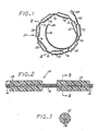
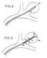
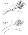
- a vascular embolization device 10 in accordance with a first preferred embodiment of the present invention, is shown in Figures 1, 2 and 3 .
- the embolization device 10 comprises a plurality of embolizing bodies, each configured as a substantially cylindrical "micropellet" 12, located at spaced intervals along a filamentous carrier 14.
- the number of micropellets 12 will vary, depending on the length of the carrier 14, which, turn, will depend on the size of the vascular site to be embolized. For a large vascular site, for example, eight to twelve micropellets may be used, although an even larger number may be used if necessary. In some applications (e.g., very small aneurysms), as few as one or two micropellets may be used.
- the carrier 14 is also carried on the carrier 14 a plurality of highly flexible microcoil spacers 16, each of which is disposed between and separates a pair of micropellets 12.
- the carrier 14 has a distal portion on which is carried a relatively long distal microcoil segment 18 that is retained in place by a distal retention member 20.
- the carrier 14 has a proximal portion on which is carried a relatively long proximal microcoil segment 22.
- the proximal end of the device 10 is terminated by a hydrogel linkage element 24, to be described below.
- the spacers 16, the distal microcoil segment 18, and the proximal microcoil segment 22 are all highly flexible, and they are preferably made of platinum or platinum/tungsten wire, which has the advantages of being biocompatible and radiopaque.
- micropellets 12 are non-releasably carried on the carrier 14. They may be fixed in place on the filamentous carrier 14, either mechanically or by a suitable biocompatible, water-insoluble adhesive, or they may be simply strung loosely on the carrier 14 between successive spacers 16.
- the micropellets 12 are preferably formed of a biocompatible, macroporous, hydrophilic hydrogel foam material, in particular a water-swellable foam matrix formed as a macroporous solid comprising a foam stabilizing agent and a polymer or copolymer of a free radical polymerizable hydrophilic olefin monomer cross-linked with up to about 10% by weight of a multiolefin-functional cross-linking agent.
- a suitable material of this type is described in U.S. Patent No. 5,570,585 - Park et al.
- Another suitable material for the micropellets 12 is a porous hydrated polyvinyl alcohol (PVA) foam gel prepared from a polyvinyl alcohol solution in a mixed solvent consisting of water and a water-miscible organic solvent, as described, for example, in U.S. Patent No. 4,663,358 - Hyon et al.
- PVA polyvinyl alcohol
- Other suitable PVA structures are described in U.S. Patents Nos. 5,823,198 - Jones et al. and 5,258,042 - Mehta .
- Another suitable material is a collagen foam, of the type described in U.S. Patent No. 5,456,693 - Conston et al.
- Still another suitable material is PHEMA, as discussed in the references cited above. See, e.g., Horak et al., supra , and Rao et al., supra .
- each of the embolizing micropellets 12 has an initial diameter of not more than about 0.5 mm prior to expansion in situ , with an expanded diameter of at least about 3 mm.
- the micropellets 12 may be compressed to the desired size from a significantly larger initial configuration. The compression is performed by squeezing or crimping the micropellets 12 in a suitable implement or fixture, and then "setting" them in the compressed configuration by heating and/or drying.
- Each of the micropellets 12 is swellable or expansible to many times (at least about 25 times, preferably about 70 times, and up to about 100 times) its initial (compressed) volume, primarily by the hydrophilic absorption of water molecules from an aqueous solution (e.g., resident blood plasma and/or injected saline solution), and secondarily by the filling of its pores with blood.
- the micropellets 12 may be coated with a water-soluble coating (not shown), such as a starch or a suitable polymer, to provide a time-delayed expansion.
- a temperature-sensitive coating that disintegrates in response to normal human body temperature. See, e.g., U.S. Patents Nos. 5,120,349 - Stewart et al. and 5,129,180 - Stewart .
- the foam material of the embolizing micropellet 12 may advantageously be modified, or provided with additives, to make the device 10 visible by conventional imaging techniques.
- the foam can be impregnated with a water-insoluble radiopaque material such as barium sulfate, as described by Thanoo et al., "Radiopaque Hydrogel Microspheres", J. Microencapsulation, Vol. 6, No. 2, pp. 233-244 (1989 ).
- the hydrogel monomers can be copolymerized with radiopaque materials, as described in Horak et al., "New Radiopaque PolyHEMA-Based Hydrogel Particles", .J. Biomedical Materials Research, Vol. 34, pp. 183-188 (1997 ).
- the micropellets 12 may optionally include bioactive or therapeutic agents to promote thrombosis, cellular ingrowth, and/or epithelialization. See, e.g, Vacanti et al., "Tissue Engineering: The Design and Fabrication of Living Replacement Devices for Surgical Reconstruction and Transplantation," The Lancet (Vol. 354, Supplement 1), pp. 32-34 (July, 1999 ); Langer, “Tissue Engineering: A New Field and Its Challenges," Pharmaceutical Research, Vol. 14., No. 7, pp. 840-841 (July, 1997 ); Persidis, "Tissue Engineering," Nature Biotechnology, Vol. 17, pp. 508-510 (May, 1999 ).
- the filamentous carrier 14 is preferably a length of nickel/titanium wire, such as that marketed under the trade name "Nitinol". Wire of this alloy is highly flexible, and it has an excellent “elastic memory", whereby it can be formed into a desired shape to which it will return when it is deformed.
- the wire that forms the carrier 14 has a diameter of approximately 0.04 mm, and it is heat-treated to form a multi-looped structure that may assume a variety of three-dimensional shapes, such as a helix, a sphere, or an ovoid when unconstrained (as disclosed, for example, in U.S. Patent No. 5,766,219 - Horton ).
- the intermediate portion of the carrier 14 i.e., the portion that includes the micropellets 12
- the proximal portion that carries the proximal microcoil segment 22
- the distal portion that carries the distal microcoil segment 18
- the carrier 14 may be formed of a single wire, or it may be formed of a cable or braided structure of several ultra-thin wires.
- the carrier 14 may be made of a thin filament of a suitable polymer, such as a PVA, that is formed in a looped structure.
- the polymer may be impregnated with a radiopaque material (e.g., barium sulfate or particles of gold, tantalum, or platinum), or it may enclose a core of nickel/titanium wire.
- the carrier 14 may be constructed as a "cable" of thin polymer fibers that includes fibers of an expansile polymer, such as polyvinyl alcohol (PVA), at spaced intervals to form the micropellets 12.
- PVA polyvinyl alcohol
- Still another alternative construction for the carrier 14 is a continuous length of microcoil.
- the micropellets 12 would be attached at spaced intervals along the length of the carrier 14.
- the hydrogel linkage element 24 is advantageously made of the same material as the micropellets 12. Indeed, the most proximal of the micropellets 12 may function as the linkage element 24.
- the linkage element 24 is attached to the proximal end of the carrier 14 by a suitable biocompatible adhesive.
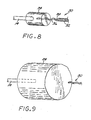
- the purpose of the linkage element 24 is to removably attach the device 10 to a deployment instrument 30 ( Figures 8 and 9 ).
- the deployment instrument 30 comprises a length of platinum or platinum/tungsten microcoil outer portion 32 with a flexible wire core 34 of the same or a similar metal.
- the deployment instrument 30 has a distal portion 36 at which the microcoil outer portion 32 has coils that are more distantly-spaced (i.e., have a greater pitch).
- the device 10 is initially attached to the deployment instrument 30 by means of the linkage element 24.
- the linkage element 24 is installed, in a compressed state, so that it encompasses and engages both the proximal end of the embolization device 10 and the distal portion 36 of the deployment instrument 30.
- the linkage element 24 binds the deployment instrument 30 and the embolization device 10 together.
- the linkage element 24 expands greatly, thereby loosening its grip on the distal portion 36 of the deployment instrument 30, and thus allowing the embolization device 10 to be separated from the deployment instrument 30 by pulling the latter proximally out of and away from the linkage element 24.
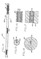
- FIGS 14 through 23 illustrate an embolization device in accordance with a second preferred embodiment of the present invention.
- a device 100 in accordance with this second embodiment comprises an elongate, flexible, filamentous carrier 102 on which an expansile embolizing element 104 is non-releasably carried.
- the carrier 102 is preferably formed from a continuous length of hollow microcoil 106, made from a suitable metal such as platinum, gold, tungsten, or tantalum, or a metallic alloy, such as stainless steel or Nitinol. Of these materials, platinum and Nitinol are preferred.
- the microcoil is formed with tightly-packed coils, so that there is little or no spacing between adjacent coils.
- the carrier 102 may also include a filamentous core 108 extending axially through the microcoil 106.
- the core 108 is a thin metal wire, preferably made of a shape memory metal such as Nitinol.
- the device 100 includes a distal portion comprising an outer coil 110 coaxially surrounding the microcoil 106, and terminating in a rounded distal tip 112.
- a hydrogel linkage element (not shown), of the type described above and illustrated in Figures 8 and 9 , may advantageously be provided at the proximal end of the carrier.
- the carrier 102 may, alternatively, be made of any of the materials described above with respect to the carrier of the first preferred embodiment. While it is preferably in the configuration of a microcoil, it may also be formed as a single strand of metal wire or polymeric filament, or as a multi-strand braid or cable of metal wire or polymeric filament.
- the carrier should have a column strength sufficient to allow it to be pushed through a microcatheter, as mentioned above.
- the expansile embolizing element 104 is advantageously formed as a hydrogel layer covering a substantial portion of the length of the carrier 102.
- the embolizing element 104 may be made of any of the materials used in the embolizing elements of the above-described first preferred embodiment.
- the embolizing element 104 of this second embodiment is preferably formed of a porous, environmentally-sensitive, expansile hydrogel, of the type described in prior co-pending U.S. Patent No. 6,878,384 .
- a brief description of a suitable formulation of a preferential hydrogel is set forth below.
- hydrogels described in the above-referenced prior application are of a type that experience an increase in lubricity and undergo controlled volumetric expansion in an aqueous environment at a rate that changes in response to changes in a physical parameter of the environment, such as its pH or temperature.
- These hydrogels are prepared by forming a liquid mixture that contains (a) at least one monomer and/or polymer, at least a portion of which is sensitive to changes in an environmental parameter; (b) a cross-linking agent; and (c) a polymerization initiator.
- a porosigen e.g., NaCl, ice crystals, or sucrose
- a porosigen may be added to the mixture, and then removed from the resultant solid hydrogel to provide a hydrogel with sufficient porosity to permit cellular ingrowth.
- the controlled rate of expansion is provided through the incorporation of ethylenically unsaturated monomers with ionizable functional groups (e.g., amines, carboxylic acids).
- ionizable functional groups e.g., amines, carboxylic acids.
- acrylic acid is incorporated into the crosslinked network
- the hydrogel is incubated in a low pH solution to protonate the carboxylic acids. After the excess low pH solution is rinsed away and the hydrogel dried, the hydrogel can be introduced through a microcatheter filled with saline at physiological pH or with blood.
- the hydrogel cannot expand until the carboxylic acid groups deprotonate.
- an amine-containing monomer is incorporated into the crosslinked network, the hydrogel is incubated in a high pH solution to deprotonate amines. After the excess high pH solution is rinsed away and the hydrogel dried, the hydrogel can be introduced through a microcatheter filled with saline at physiological pH or with blood. The hydrogel cannot expand until the amine groups protonate.
- the monomer solution is comprised of ethylenically unsaturated monomers, an ethylenically unsaturated crosslinking agent, a porosigen, and a solvent. At least a portion, preferably 10% - 50%, and more preferably 10% - 30%, of the monomers selected must be pH sensitive.
- the preferred pH sensitive monomer is acrylic acid. Methacrylic acid and derivatives of both acids will also impart pH sensitivity. Since the mechanical properties of hydrogels prepared exclusively with these acids are poor, a monomer to provide additional mechanical properties should be selected.
- a preferred monomer for providing mechanical properties is acrylamide, which may be used in combination with one or more of the above-mentioned pH sensitive monomers to impart additional compressive strength or other mechanical properties.
- Preferred concentrations of the monomers in the solvent range from 20% w/w to 30% w/w.
- the crosslinking agent can be any multifunctional ethylenically unsaturated compound, preferably N, N'-methylenebisacrylamide. If biodegradation of the hydrogel material is desired, a biodegradable crosslinking agent should be selected.
- concentrations of the crosslinking agent in the solvent should be less than about 1% w/w, and preferably less than about 0.1% w/w.
- the porosity of the hydrogel material is provided by a supersaturated suspension of a porosigen in the monomer solution.
- a porosigen that is not soluble in the monomer solution, but is soluble in the washing solution can also be used.
- Sodium chloride is the preferred porosigen, but potassium chloride, ice, sucrose, and sodium bicarbonate can also be used.
- the small particle size aids in the suspension of the proposigen in the solvent.
- Preferred concentrations of the porosigen range from about 5% w/w to about 50% w/w, more preferably about 10% w/w to about 20% w/w, in the monomer solution.
- the porosigen can be omitted and a non-porous hydrogel can be fabricated.
- the solvent if necessary, is selected based on the solubilities of the monomers, crosslinking agent, and porosigen. If a liquid monomer (e.g. 2-hydroxyethyl methacrylate) is used, a solvent is not necessary.
- a preferred solvent is water, but ethyl alcohol can also be used. Preferred concentrations of the solvent range from about 20% w/w to about 80% w/w, more preferably about 50% w/w to about 80% w/w.
- the crosslink density substantially affects the mechanical properties of these hydrogel materials.
- the crosslink density (and hence the mechanical properties) can best be manipulated through changes in the monomer concentration, crosslinking agent concentration, and solvent concentration.
- the crosslinking of the monomer can be achieved through reduction-oxidation, radiation, and heat. Radiation crosslinking of the monomer solution can be achieved with ultraviolet light and visible light with suitable initiators or ionizing radiation (e.g. electron beam or gamma ray) without initiators.
- a preferred type of crosslinking initiator is one that acts via reduction-oxidation. Specific examples of such red/ox initiators that may be used in this embodiment of the invention are ammonium persulfate and N,N,N',N'-tetramethylethylenediamine.
- the hydrogen is washed with water, alcohol or other suitable washing solution(s) to remove the porosigen(s), any unreacted, residual monomer(s) and any unincorporated oligomers.
- water, alcohol or other suitable washing solution(s) Preferably this is accomplished by initially washing the hydrogel in distilled water.
- the control of the expansion rate of the hydrogel is achieved through the protonation/deprotonation of ionizable functional groups present on the hydrogel network.
- the hydrogel is incubated in a low pH solution.
- the free protons in the solution protonate the carboxylic acid groups on the hydrogel network.
- the duration and temperature of the incubation and the pH of the solution influence the amount of control on the expansion rate.
- the duration and temperature of the incubation are directly proportional to the amount of expansion control, while the solution pH is inversely proportional. It has been determined that the water content of the treating solution also affects the expansion control.
- the hydrogel is able to expand more in the treating solution and it is presumed that an increased number of carboxylic acid groups are available for protonation.
- the hydrogel is incubated in high pH solution. Deprotonation occurs on the amine groups of the hydrogel network at high pH.
- the duration and temperature of the incubation, and the pH of the solution influence the amount of control on the expansion rate. Generally, the duration, temperature, and solution pH of the incubation are directly proportional to the amount of expansion control. After the incubation is concluded, the excess treating solution is washed away and the hydrogel material is dried.
- the formulation of the hydrogel polymer of the member can be modified to incorporate polymers that degrade, or break down, in the body after a period of time in response to, e.g., hydrolysis or enzymatic action, into simpler molecular constituents that can be absorbed by the patient's body and/or eliminated from it as waste.
- Polymers suitable for incorporation into the embolization device for this purpose include those described in: " Types of Biodegradable Hydrogels," Biodegradable Hydrogels for Drug Delivery, K. Park et al., Technomic Publishing 1993, pp. 35-66 ; U.S. Pats. No.
- the member can be made such that it is biodegradable and/or bioresorbable in the patient's body, where such properties are clinically indicated.
- an embolic device 100 in accordance with this second embodiment may include more than one elongate expansile embolizing elements 104. Also, if desired for a particular application, two or more embolizing devices 100 can be joined end-to-end at a juncture 114 formed by a weld or a solder joint.
- FIGs 14, 15, and 16 show the device 100 with the embolizing elements 104 in their non-expanded state.
- Each embolizing element 104 assumes a tubular configuration in the form of a coating or layer on the exterior surface of the carrier 102.
- Figures 17 and 18 show an embolizing element 104 in its expanded state after deployment in a vascular site. If made from the environmentally-sensitive hydrogel described above, the expansion is a reaction to the pH and/or temperature experienced in the vascular site. The expansion begins between about 1 minute and about 30 minutes after deployment, and preferably about 15 minutes after deployment. This delayed expansion allows the physician sufficient time to reposition and even withdraw the device without the need for a restraining agent, encapsulating layer, or a non-aqueous carrier fluid.
- the embolizing element 104 has an expanded volume that is between about two times and about 100 times its non-expanded volume, and preferably between about 3 times and about 25 times its non-expanded volume.
- a modified embolic device 100' comprises an elongate, flexible, filamentous carrier.
- the carrier comprises an elongate, hollow microcoil 106' that is similar to the microcoil 106 shown in Figures 14-17 , except that it has significant spaces between adjacent coils.
- the carrier of the device 100' may advantageously include a central axial core 108', formed of a thin, flexible wire.
- An expansile embolizing element 104' made of any of the above-described hydrogels, is formed on the carrier so that it resides between adjacent coils of the microcoil 106', thereby encapsulating them.
- Figure 19 shows the embolizing element 104' in its non-expanded state, while Figure 20 shows it in its expanded state, after deployment.
- An embolic device 100" in accordance with this version comprises an elongate, filamentous carrier, preferably in the form of a hollow, flexible microcoil 106". Although the carrier is shown without a wire core, it is understood that a wire core may be included, as described above.
- a plurality of expansile embolizing elements 120 are formed as fibers or threads that are attached to the microcoil 106" at spaced-apart intervals along its length.
- Each of the expansile embolizing elements 120 is preferably made of an environmentally-sensitive hydrogel, of the type described in the prior co-pending application described above, although the hydrogel described in the U.S. Pat.
- An embolic device 100'" in accordance with this version comprises an elongate, filamentous carrier, preferably in the form of a hollow, flexible microcoil 106"'.
- the carrier may include a wire core, although one is not shown in the drawing.
- This version includes an elongate coaxial embolizing element 104"' that is in the form of a stretch-resistant outer layer applied to the exterior of the microcoil 106'" along a substantial portion of the its length.
- the stretch-resistant outer layer is preferably formed of an expansile polymer, such as those described above, but it may also be formed of any stretch-resistant, biocompatible polymer, such as, for example, polyurethane, polyester, polytetrafluoroethylene (PTFE), nylon, polymethylmethacrylate (PMMA), and silicone.
- PTFE polytetrafluoroethylene
- PMMA polymethylmethacrylate
- the Embolization Device Third Exemplary Embodiment and First Method for Making It : A third exemplary embodiment of a device 300 for occluding a body cavity is illustrated in Figures 32-35 , and a first exemplary embodiment of a method for making the third embodiment of the device 300 is illustrated in Figures 24-31 .
- the embolization device 300 comprises an elongated, filamentous carrier 302, and an embolizing element comprising a coaxial member 304 of an expansile, hydrophilic polymer, or hydrogel, described in detail above, encapsulating at least a portion of the length of the carrier.
- coaxial polymer embolizing member 304 is shown in the figures as having a substantially cylindrical shape, it should be understood that the member, and indeed, the carrier encapsulated within it, can have a wide variety of other cross-sectional shapes, e.g. , polygonal, longitudinally grooved, and the like, depending on the particular application at hand.
- the carrier 302 may, as in the first and second embodiments of device described above, comprise either an elongated strand of a flexible, biocompatible material, e.g. , a platinum wire, or a flexible tube.
- a tubular carrier such as a tubular braid or the flexible, hollow microcoil 302 described above and illustrated in the exemplary embodiment of Figure 32
- the coaxial polymer member 304 is formed on the carrier by the method described below such that the hollow lumen of the carrier is substantially void of the polymer, thereby defining an axial reservoir 306 in the carrier, as shown in Figure 35 .
- the reservoir 306 in the carrier 302 constitutes a reservoir in which therapeutic agents, in either a liquid or a solid form, can be disposed for delivery to a patient via emplacement of the device 300 in a body cavity of the patient, as described below.
- FIG. 24 A first exemplary embodiment of a method for making the exemplary third embodiment of the device 300 is illustrated in Figures 24-31 of the drawings.
- the method begins with the provision of a softened, elongated member 304 of a expansile, hydrophilic polymer, such as hydrogel. Since the softness of the polymer is a function of the degree of its hydration, the elongated member 304 can be softened by immersing it in a bath of water until it reaches the desired state of softness, viz., about that of fully cooked pasta.
- the softened polymer member 304 When hydrated to the desired state, the softened polymer member 304 is inserted into a tubular holder 308 such that the member is radially confined and axially restrained in the holder, as illustrated in Figure 25 . In one possible embodiment, this is effected by inserting a partially hydrated member 304 into the holder 308, then immersing both in a bath of water until the member expands in the holder to the desired state of support and retention therein.
- the member is then coaxially skewered with an elongated, flexible, filamentous carrier 302 such that the polymer member coaxially encapsulates at least a portion of the length of the carrier.
- the carrier 302 comprises an elongated strand, such as a wire
- this procedure is effected by simply pushing one end of the wire coaxially through the softened member 304, provided the wire is sufficiently straight and stiff, or if not, then by attaching a first end of the wire to the eye of a needle (not illustrated), then forcing the needle through the softened member coaxially, such that the carrier is pulled coaxially through the member by the needle.
- a stiff, elongated support mandrel 316 is first inserted coaxially in the lumen of the carrier to straighten and stiffen it, as shown in Figure 26 .
- the soft polymer member 304 is then coaxially skewered with the carrier supported on the mandrel, such that the polymer member coaxially encapsulates at least a portion of the length of the carrier, as shown in Figure 27 .
- the skewered polymer member 304 and carrier 302 are ejected from the tubular holder 308 to define a partially finished embolization device 300.
- this ejection is effected by placing a nozzle 310 against one end of the tubular holder 308 and forcing the skewered member 304 out of the other end of the holder with hydraulic pressure applied through the nozzle.
- the lumenal mandrel 316 may be withdrawn from the device to define the axial reservoir 306 in the carrier 302, as shown in Figure 35 , or alternatively, the mandrel may be left in the carrier to support the device during the subsequent processes applied to it.
- the first of these post-skewering processes comprises dehydrating the coaxial polymer member 304 of the device 300, e.g., by immersion of the device in a hygroscopic medium, e.g., an alcohol bath 312, to remove water from, and thereby shrink, the coaxial polymer member radially from its original soft, expanded size, represented by the phantom outline 314 in Figure 29 , to a thinner, drier member more suitable for passage through the lumen of a catheter, as illustrated.
- a hygroscopic medium e.g., an alcohol bath 312
- the polymer member 304 of the device 300 is washed, then treated, e.g., by immersing the device in an acid bath 318 of a selected strength and for a selected period of time, as illustrated in Figure 30 , to set the rate of hydration of the polymer, and hence, the rate of expansion, of the coaxial polymer member 304, in an aqueous environment, e.g., blood or plasma, in response the level of a physical parameter of that environment, e.g., its temperature or pH level, as described above.
- an aqueous environment e.g., blood or plasma
- the device 300 After the hydration rate of the device 300 has been set, it is washed, preferably in a solution of water and alcohol, to remove any processing impurities, and then dried by heating, e.g., by baking in an oven 320, as illustrated in Figure 31 .
- the dry, finished embolization device 300 may then be packaged in a sterile container for storage or shipment.
- the Embolization Device Fourth Exemplary Embodiment and Second Method for Making It : A fourth exemplary embodiment of an embolization device 400 for occluding a body cavity is illustrated in Figures 39-42 , and a second exemplary embodiment of a method for making the fourth embodiment of the device 400 is illustrated in Figures 36-38 .
- two possible variants of the fourth exemplary embodiment of embolization device 400 both comprise, as in the case of the third exemplary embodiment 300 described above, an elongated, filamentous carrier 402, and a coaxial member 404 of an expansile, hydrophilic polymer, or hydrogel, encapsulating at least a portion of the length of the carrier.
- the carrier 402 may, like the third embodiment above, comprise either an elongated strand of a flexible, biocompatible material, e.g., platinum wire, or a flexible tube.
- the coaxial polymer member 404 is formed on the carrier by the method described below in such a way that the lumen of the carrier is substantially occupied by the polymer, whereby no axial reservoir is created in the carrier, as illustrated in the enlarged cross-sectional views thereof of Figures 40A and 40B .
- the coaxial polymer member 404 can be formed on the carrier in a variation of the method described below such that the hollow lumen of the carrier is substantially void of the polymer, thereby defining an axial reservoir 406 in the carrier, as illustrated in Figures 42A and 42B , in a manner similar to that created in the third embodiment 300 described above and.illustrated in Figure 35 .
- the second exemplary embodiment of a method for making the exemplary fourth embodiment of the device 400 is illustrated in Figures 36-38 .
- the method begins with the provision of a mold 408 having an elongated cavity 410 therein.
- the mold 408 may also include a vent 412 for venting air from the cavity 410 during the molding operation described below.
- An elongated filamentous carrier 402 which may comprise a tubular, helically coiled carrier, as above, is disposed coaxially within the cavity 410 of the mold 408.
- the carrier is elastically stretched along its axis, such that the coils 414 of the carrier are held spaced apart from each other while the carrier is disposed in the mold 408, as shown in the enlarged cross-sectional view of Figure 37 .
- the coils 414 of a helical carrier 402 are formed such that they are spaced apart permanently, i.e., without stretching the carrier in the mold 408.
- a support mandrel 416 is inserted coaxially in the lumen of a helical carrier 402, which may have either closely spaced or spaced-apart helical coils 414, in a manner similar to that described above in connection with the first method, before the carrier is disposed in the cavity 410 of the mold 408.
- a quantity of a expansile, hydrophilic polymer 418 which has been softened by hydration to a viscosity that is about the same as that described above in connection with the first exemplary method embodiment, is transferred into the mold under pressure, as illustrated in Figure 36 , such that the polymer is molded by the cavity into a member 404 that coaxially encapsulates at least a portion of the length of the carrier 402, and in those variants in which the carrier comprises a lumen that is not occupied by a mandrel 416, such that the polymer also flows into and substantially occupies the lumen of the carrier, as illustrated in the enlarged cross-sectional view of Figure 38 .
- the partially finished embolization device 400 is released from the mold 408.
- the appearance of the molded device 400 is similar to those illustrated in Figures 39 and 41 , except that the molded polymer member 404 is still soft and swollen by hydration. Consequently, in those variants of the method in which a helical carrier 402 has been retained in the mold 408 in an elastically stretched condition, this release from the mold causes the adjacent coils 414 of the carrier to spring back into contact with one another through the still-soft polymer member 404, as shown in the enlarged cross-sectional view of Figure 40A .
- the post-molding processes applied to the fourth exemplary embodiment of the embolization device 400 are substantially the same as those applied to the third exemplary embodiment of the device 300 in the first exemplary method described above, including dehydration of the coaxial member 404, adjustment of its rate of hydration, and the washing, drying and sterile packaging of the device.
- the lumenal support mandrel 316 or 416 can be removed from the carrier 302 or 402 at any stage of the process after the skewered or molded coaxial member 304 or 404 is ejected or released from the holder 308 or mold 408, and before the dried and finished device 300 or 400 is packaged. Removal of the mandrel creates an axial reservoir 306 or 406 in the carrier that, as described above, can be used as a receptacle for the delivery of therapeutic agents, e.g., medications, blood cells, and the like, to a patient via implantation of the device.
- therapeutic agents e.g., medications, blood cells, and the like
- a wide variety of therapeutic agents can be effectively delivered via the axial cavities 306, 406 of the devices 300, 400, and includes such agents as: drugs; growth factors; proteins; clotting agents; sclerosants; anti-infectives, such as antibiotics and antiviral agents; chemotherapeutic agents; anti-rejection agents; analgesics and analgesic combinations; anti-inflammatory agents; hormones, such as steroids; growth factors; and, other naturally derived or genetically engineered proteins, polysaccharides, glycoproteins, or lipoproteins.
- an exemplary method for delivering a therapeutic agent to a patient comprises providing an embolization device 300 or 400 in accordance with the third or fourth exemplary embodiments thereof described above, disposing a therapeutic agent in the axial reservoir 306 or 406 of the carrier 302 or 402 of the device, and implanting the device in a body cavity of the patient in accordance with one of the methods described below.
- the properties of the hydrophilic polymer is such that the flexibility, size, and lubricity of the polymer of the coaxial embolizing member 304, 404, and hence, the device itself, all increase with the degree of hydration of the polymer.
- the rate of hydration of the polymer in response to a physical parameter, e.g., the pH or temperature, of an aqueous environment can be set at the time of device manufacture.
- the dry device is first immersed in an aqueous medium, e.g., a saline solution, having a relatively low pH level of about 5, such that the rate of hydration of the coaxial polymer member in the medium is correspondingly relatively slow.
- an aqueous medium e.g., a saline solution
- the rate of hydration increases substantially in response to the increased physiological pH level of the surrounding aqueous environment, e.g., blood or plasma, which have pH levels of between about 7.0 and 7.5, such that the coaxial member of the device then rapidly expands to occlude the cavity.
- the formulation of the polymer of the coaxial member 304 or 404 can be modified to incorporate polymers that degrade, or break down after a period of time by, e.g., hydrolysis or enzymatic reaction in the body cavity into simpler molecular constituents that can be easily and safely absorbed by the body and/or eliminated from it as waste.
- the member in another possible embodiment of the device incorporating a coaxial embolizing member comprising hydrogel, the member can be made such that it is biodegradable and/or bioresorbable in the patient's body.
- Figure 43 illustrates a quick and convenient method known in the industry for determining the flexibility, or conversely, the stiffness, of an embolization device in accordance with this invention, as taught in, e.g. , U.S. Pat. No. 5,690,666 - A. Berenstein et al.
- an exemplary device 420 is supported on a first horizontal surface 422 such that a portion 424 of the device overhangs a second horizontal surface 426 disposed vertically below the first surface by an arbitrary, fixed height 428, and such that the unsupported end 430 of the overhanging portion just touches the second surface.
- the overhanging portion 424 of the device 420 takes on a curved shape, due to the weight of the overhanging portion, as shown in the enlarged, partial cross-sectional detail view of Figure 44 , and the horizontal distance 432 between the unsupported end 430 and the supported end 434 of the overhanging portion provides a measure of the flexibility, or conversely, the stiffness of the device.
- the stiffer the device the longer the horizontal distance 432 between the two ends 430 and 434, and vice-versa.
- an exemplary embolization device in accordance with the present invention may have, by way of example and without limitation, a stiffness, or flexibility, as indicated by the horizontal distance 432 between the two ends 430 and 434, of more than about 2.25 inches (57.2 mm) when the hydrogel is in a dry (i.e., least flexible) state, between about 1.5 in. (38.2 mm) and 2.25 in. (57.2 mm) when the hydrogel is in a moderately hydrated (i.e., more flexible) state, and less than about 1.5 in (38.2 mm) when the hydrogel is in a fully hydrated (i.e., most flexible) state.
- a stiffness, or flexibility as indicated by the horizontal distance 432 between the two ends 430 and 434, of more than about 2.25 inches (57.2 mm) when the hydrogel is in a dry (i.e., least flexible) state, between about 1.5 in. (38.2 mm) and 2.25 in. (57.2 mm) when the hydrogel is in a moderate
- the Method for Embolizing a Vascular Site One method of embolizing a vascular site using either the embolization device 10 (first preferred embodiment) or the embolizing device 100 (second preferred embodiment) is illustrated in Figures 4 through 7 . This method will be described with reference to the embolic device 10 of the first preferred embodiment, but it will be appreciated that this method is equally applicable to the device 100 of the second preferred embodiment.
- a microcatheter 40 is threaded intravascularly, by known methods, until its distal end is located within the targeted vascular site (here, an aneurysm 42). Briefly described, this threading operation is typically performed by first introducing a catheter guidewire (not shown) along the desired microcatheter path, and then feeding the microcatheter 40 over the catheter guidewire until the microcatheter 40 is positioned adjacent the distal aspect of the dome of the aneurysm, as shown in Figure 4 . The catheter guidewire is then removed.
- the embolization device 10 which is attached to the distal end of the deployment instrument 30, as described above, is passed axially through the microcatheter 40, using the deployment instrument 30 to push the device 10 through the microcatheter 40 until the device 10 is clear from the distal end of the microcatheter 40 and fully deployed within the aneurysm 42 ( Figure 6 ), filling the aneurysm from its distal aspect.
- the deployment procedure is facilitated by the visualization of the embolization device 10 that is readily accomplished due to its radiopaque components, as described above.
- the embolization bodies or micropellets 12 in their compressed configuration, have a maximum outside diameter that is less than the inside diameter of the microcatheter 40, so that the embolization device 10 can be passed through the microcatheter 40.
- the micropellets 12 are preferably compressed and "set", as described above, before the device 10 is inserted into the microcatheter 40.
- a biocompatible, substantially non-aqueous fluid such as polyethylene glycol, may be injected into the microcatheter 40 to prevent premature expansion of the device 10 due to hydration, and to reduce friction with the interior of the microcatheter 40.
- the pores of the embolizing bodies or micropellets 12, and of the linkage element 22 begin to absorb aqueous fluid from the blood within the vascular site 42 to release their "set", allowing these elements to begin assuming their expanded configuration.
- the expansion can be enhanced and accelerated by injecting saline solution through the microcatheter 40.
- the expansion of the linkage element 24 allows the embolization device 10 to be separated from the deployment instrument 30, as described above, and the deployment instrument 30 can then be removed.
- the elastic memory of the carrier 14 causes it to resume its original looped configuration once it is released from the confines of the microcatheter 40.
- the embolization device begins to occupy a significant portion of the volume of the aneurysm 42.
- micropellets 12 are of a hydrophilic material, they then continue to expand in situ due to hydrophilic hydration of the material, as well as from the filling of their pores with blood. If the embolizing bodies 12 are of a non-hydrophilic material, their expansion is due to the latter mechanism only. In either case, the result, as shown in Figure 7 , is the substantially complete filling of the interior of the aneurysm 42 with the expanded embolizing bodies or micropellets 12, whereby a substantially conformal embolizing implant 44 is formed that substantially fills the interior of the aneurysm 42.
- the embolizing element 104 is not compressed in its initial configuration. Rather, it initially has a configuration in which its outside diameter is small enough to pass through the typical microcatheter. Once deployed within the target vascular site, the embolizing element 104 expands solely by hydration.
- a device 10 of the appropriate size can be selected that would expand to fill the measured or estimated volume.
- a preferred method of embolizing a target vascular site using the embolization device 10 will be understood with reference to Figures 10-12 , along with Figures 4-7 (discussed above).
- the passing of a microcatheter 40 intravascularly until its distal end is introduced into a target vascular site is followed by the step of passing a vaso-occlusive device 50 through the microcatheter 40 into the target vascular site (e.g., the aneurysm 42) so that the vaso-occlusive device 50 assumes a three-dimensional configuration that fills a portion of the interior volume of the target vascular site 42, as shown in Figure 10 .
- the deployed vaso-occlusive device 50 forms a "cage" within the aneurysm 42 that provides a matrix for improved retention of the expansible embolizing bodies or micropellets 12 of the embolization device 10.
- the embolization device 10 is then passed through the microcatheter 40, as described above, and as shown in Figure 11 , to enter the aneurysm 42 within the voids left by the vaso-occlusive device 50.
- the embolizing bodies or micropellets 12 are expanded, as described above, and as shown in Figure 12 , whereby a substantially conformal embolizing implant 44' is formed that fills a substantial portion of the interior volume of the aneurysm 42. Specifically, at least about 30%, and preferably at least about 40% of the interior volume is filled, and, it is believed that in some situations, as much as about 80% to 90% of the interior volume may be filled.
- the vaso-occlusive device 50 is of the type that is initially in the form of an elongate, flexible, filamentous element for delivery through the microcatheter, and that assumes a three-dimensional geometry (either by elastic behavior or by shape memory) upon installation in the target vascular site.
- Such devices are describe in, for example, U.S. Patents Nos. 5,122,136 - Guglielmi et al. ; 5,766,219 - Horton ; 5,690,671 - McGurk et al. ; and 5,911,731 - Pham et al.
- Still other types of vaso-occlusive devices known in the art may also perform satisfactorily in this method.
- vaso-occlusive device 50 may be designed or installed only to enter the space near the opening or "neck" of the aneurysm.
- the purpose of the vaso-occlusive device 50 in this method is to present a structural framework that helps retain the embolization device 10 in place within the target vascular site.
- the method includes the preliminary step of deploying an intravascular device 60 to a position in a blood vessel 62 adjacent to a target vascular site 42.
- a microcatheter 40' is passed intravascularly so that its distal end passes through the intravascular device 60 into the target vascular site 42.
- the embolization device 10 is passed through the microcatheter 40' so that it emerges from the distal end of the microcatheter 40' into the target vascular site 42, and the embolizing elements 12 are then expanded in situ , as described above, substantially to fill the volume of the target vascular site 42 (as shown in Figures 7 and 12 ).
- the step of deploying an intravascular device to a position in a blood vessel adjacent to a target vascular site would include any sub-steps necessary for such deployment.
- the deployment step would comprise the sub-steps of (i) passing of a microcatheter intravascularly so that its distal end is located adjacent the target vascular site; (ii) passing the intravascular device through the microcatheter until it emerges from the distal end of the microcatheter; and (iii) allowing the intravascular device to assume a three-dimensional configuration adjacent to the target vascular site.
- the microcatheter used for deploying the intravascular device could be removed and then another microcatheter used to install the embolization device, or the intravascular deployment microcatheter could be repositioned for the introduction of the embolization device.
- the intravascular device presents an obstruction that at least partially blocks the juncture between the target vascular site and the blood vessel (e.g., the neck of an aneurysm).
- the intravascular device helps retain the embolization device in its proper position within the target vascular site.
- the embolic device in accordance with the present invention has been described above for use in embolizing aneurysms, other applications will readily suggest themselves. For example, it can be used to treat a wide range of vascular anomalies, such as arteriovenous malformations and arteriovenous fistulas. Certain tumors may also be treated by the embolization of vascular spaces or other soft tissue voids using the present invention.
- the devices may also be used to occlude fallopian tubes for the purposes of sterilization, and the occlusive repair of cardiac defects, such as a patent foramen ovale, patent ductus arteriosis, and left-atrial- appendage and atrial-septal defects. In such circumstances, the occlusion device functions to substantially block the flow of body fluids into or through the cavity, lumen, vessel, space or defect for the therapeutic benefit of the patient.
- An exemplary method for making a body cavity occlusion device comprising:providing an elongated, flexible, filamentous carrier; and coaxially encapsulating at least a portion of the length of the carrier in an expansile, hydrophilic polymer.
- encapsulating the carrier comprises:providing an elongated member of the polymer in a softened state; and skewering the member coaxially with the carrier.
- providing the elongated member comprises inserting the member into a tubular holder such that the member is radially confined and axially restrained therein.
- encapsulating the carrier comprises: providing a mold having an elongated cavity therein; disposing the carrier coaxially within the cavity of the mold; and transferring the polymer into the cavity such that the polymer is thereby molded into a member coaxially encapsulating at least a portion of the length of the carrier.
- encapsulating the carrier comprises substantially filling the lumen of the encapsulated portion of the carrier with the polymer.
- the carrier includes an axial lumen, and further comprising forming an axial reservoir in the lumen.
- the exemplary method, herein fonning the axial reservoir comprises: inserting an elongated mandrel into the lumen of the carrier before the encapsulation thereof; and removing the mandrel from the lumen of the carrier after the encapsulation thereof.
- the exemplary method further comprising dehydrating the polymer to shrink it.
- dehydrating the polymer comprises immersing the device in a hygroscopic medium.
- dehydrating the polymer comprises heating the device.
- the exemplary method wherein the polymer has a rate of hydration in an aqueous medium that is a function of a physical parameter of the medium, and further comprising setting the rate of hydration of the polymer in response to the parameter.
- adjusting the rate of hydration comprises treating the polymer with an acid.
- the exemplary method further comprising immersing the device for a period of time in an aqueous medium having the physical parameter, wherein the period of time and the physical parameter of the medium are selected so as to soften the polymer and render it lubricious without substantially expanding it.
- An exemplary method for delivering a therapeutic agent to a patient comprising:
- An exemplary device for occluding a body cavity comprising: an elongated, flexible, filamentous carrier; and a member of an expansile, hydrophilic polymer coaxially encapsulating at least a portion of the length of the carrier.
- the exemplary device wherein the carrier includes an axial lumen, and wherein the polymer of the member substantially fills the lumen of the encapsulated portion of the carrier.
- the carrier comprises a filamentous element selected from the group consisting of a flexible wire, helical coil, and tube.
- coaxial member comprises hydrogel
- coaxial member is at least one of biodegradable and bioresorbable.
- the exemplary device wherein the coaxial member has a substantially greater lubricity when hydrated than when dry.
- a exemplary device for occluding a cavity comprising: an elongated, filamentous carrier formed of a biocompatible material having an elastic memory and an external surface; and a coaxial member of an expansile hydrogel formed over the carrier such that the member covers a substantial portion of the external surface of the carrier; wherein the device has at least one of a greater flexibility and a greater lubricity when the hydrogel is hydrated than when the hydrogel is dehydrated.
- the exemplary device wherein an unsupported end of a portion of the device deflects downward under the weight of the portion and relative to an opposite, supported end of the portion about 0.75 in. (19.1 nun) when: the hydrogel is in a dry state and a horizontal distance between the opposite ends of the portion is more than about 2.25 in. (57.2 nun); the hydrogel is in a moderately hydrated state and the horizontal length is between about 1.5 in. (38.2 mm) and 2.25 ill. (57.2 mm); and, the hydrogel is in a fully hydrated stated and the horizontal length is less than about 1.5 in (38.2 nun).
- An exemplary device for occluding a body cavity comprising: an elongated, filamentous carrier with an external surface; and a coaxial member of a hydrophilic polymer covering a substantial portion of the external surface of the carrier; wherein a physical property of the coaxial member in an aqueous environment is a function of time in the environment and a physical parameter of the environment.
- the exemplary device wherein the physical property is at least one of the flexibility and the lubricity of the member, and wherein the physical parameter of the environment is at least one of the temperature and the pH of the environment.
- An exemplary vascular embolization device comprising:
- the exemplary embolization device wherein the embolizing element is formed of a stretch-resistant, biocompatible polymer.
- the exemplary embolization device wherein the embolizing element is fonned of an expansile, hydrophilic polymer.
- the exemplary embolization device wherein the carrier comprises a material that is visible under X-rays.
- the exemplary embolization device wherein the polymer is an environmentally-sensitive polymer that changes its physical character in response to a change in an environmental parameter selected from the group consisting of temperature and pH.
- the exemplary embolization device wherein the embolizing element is expansible by a volumetric expansion factor of between about 2X and about 1 OOX.
- the exemplary embolization device wherein the embolizing element is radiopaque.
- the exemplary embolization device wherein the carrier is configured in the form of a multi-looped structure that may assume a three-dimensional shape when unconstrained
- the exemplary embolization device wherein the three-dimensional shape is selected from the group consisting of a sphere, a helix, and an ovoid.
- An exemplary vascular embolization device comprising:
- embolizing element comprises an elongate, continuous, coaxial embolizing element non-releasably fixed to the exterior surface of the carrier along a substantial portion of the length of the earner.
- embolizing element comprises a plurality of expansile polymer fibers attached to the carrier.
- the exemplary embolization device wherein the embolizing element is radiopaque.
- the exemplary embolization device wherein the carrier is configured in the form of a multi-looped structure that may assume a three-dimensional shape when unconstrained
- the exemplary embolization device wherein the three-dimensional shape is selected from the group consisting of a sphere, a helix, and an ovoid.
- An exemplary vascular embolization device comprising:
- the exemplary embolization device wherein the polymer hydrogel is of a type that expands in response to a change in an environmental parameter selected from the group consisting of temperature and pH after a predetermined time interval.
- the exemplary embolization device wherein the carrier is configured in the form of a multi-looped structure that may assume a three dimensional shape when unconstrained
- the exemplary embolization device wherein the three-dimensional shape is selected from the group consisting of a sphere, a helix, and an ovoid.
Landscapes
- Health & Medical Sciences (AREA)
- Surgery (AREA)
- Life Sciences & Earth Sciences (AREA)
- General Health & Medical Sciences (AREA)
- Heart & Thoracic Surgery (AREA)
- Vascular Medicine (AREA)
- Animal Behavior & Ethology (AREA)
- Public Health (AREA)
- Veterinary Medicine (AREA)
- Engineering & Computer Science (AREA)
- Medical Informatics (AREA)
- Molecular Biology (AREA)
- Biomedical Technology (AREA)
- Reproductive Health (AREA)
- Nuclear Medicine, Radiotherapy & Molecular Imaging (AREA)
- Epidemiology (AREA)
- Chemical & Material Sciences (AREA)
- Neurosurgery (AREA)
- Inorganic Chemistry (AREA)
- Physics & Mathematics (AREA)
- Optics & Photonics (AREA)
- Composite Materials (AREA)
- Mechanical Engineering (AREA)
- Dispersion Chemistry (AREA)
- Surgical Instruments (AREA)
- Materials For Medical Uses (AREA)
- Prostheses (AREA)
Claims (33)
- Dispositif d'embolisation vasculaire, comprenant :un support filamenteux flexible allongé (16), etun élément d'embolisation (12) fixé de manière non libérable sur le support, caractérisé en ce que l'élément d'embolisation est formé à partir d'un polymère expansible ayant un taux d'hydratation qui augmente en réponse à un niveau de pH accru d'un environnement aqueux physiologique qui l'entoure.
- Dispositif selon la revendication 1, dans lequel le polymère est un hydrogel poreux.
- Dispositif selon la revendication 1, dans lequel l'élément d'embolisation (12) comprend un élément d'embolisation coaxial continu allongé fixé de manière non libérable sur la surface extérieure du support (16) le long d'une partie substantielle de la longueur du support.
- Dispositif selon la revendication 1, dans lequel l'élément d'embolisation (12) comprend une pluralité de fibres polymères expansibles fixées sur le support.
- Dispositif selon la revendication 1, dans lequel l'élément d'embolisation (12) est radio-opaque.
- Dispositif selon la revendication 1, dans lequel le support (16) est configuré sous la forme d'une structure à plusieurs boucles qui peut prendre une forme à trois dimensions lorsqu'elle n'est pas contrainte.
- Dispositif selon la revendication 6, dans lequel la forme à trois dimensions est sélectionnée à partir du groupe constitué d'une sphère, d'une hélice et d'un ovoïde.
- Dispositif selon la revendication 1, dans lequel ledit support (16) comprend une pluralité de bobines et dans lequel ledit élément d'embolisation est disposé autour de chaque bobine de ladite pluralité de bobines.
- Dispositif selon la revendication 1, dans lequel ledit élément d'embolisation est disposé dans ledit support et sur une surface extérieure dudit support.
- Dispositif selon les revendications 1 à 9, dans lequel ledit élément d'embolisation (12) comprend une pluralité de micro-pastilles expansibles fixées à des intervalles espacés sur la longueur du support.
- Dispositif selon l'une quelconque des revendications 1 à 10, dans lequel ledit support (16) est creux.
- Dispositif selon l'une quelconque des revendications 1 à 10, dans lequel ledit support (16) est une micro-bobine.
- Dispositif selon la revendication 1 ou 11, comprenant en outre un filament disposé dans un intérieur creux dudit support.
- Dispositif selon l'une quelconque des revendications 1 à 10, dans lequel ledit support (16) est sélectionné à partir d'un groupe constitué d'un seul brin métallique de fil, d'un filament polymère, d'une tresse à plusieurs brins d'un fil métallique, et d'une tresse à plusieurs brins de filaments polymères.
- Dispositif selon la revendication 1 ou 12, dans lequel ledit support est une micro-bobine ayant des espaces entre aux moins certaines bobines qui constituent ladite micro-bobine, ledit élément d'embolisation étant disposé dans lesdits espaces entre lesdites bobines.
- Dispositif selon les revendications 1 à 15, dans lequel ledit polymère expansible est un hydrogel.
- Dispositif selon la revendication 1, 15 ou 16, dans lequel ledit élément d'embolisation (12) s'accroît entre environ 2 à 200 fois une taille non accrue dudit élément d'embolisation.
- Dispositif selon la revendication 1 ou 17, dans lequel ledit élément d'embolisation (12) s'accroît entre environ 3 à 25 fois une taille non accrue dudit élément d'embolisation.
- Procédé de fabrication d'un dispositif médical selon l'une quelconque des revendications 1 à 18, le procédé comprenant : la fourniture d'un support filamenteux souple allongé (16), et l'encapsulation de manière coaxiale d'au moins une partie de la longueur du support dans un polymère expansible de préférence hydrophile.
- Procédé selon la revendication 19, dans lequel l'encapsulation du support (16) comprend : la fourniture d'un élément allongé du polymère dans un état ramolli, et le fait d'embrocher l'élément coaxialement avec le support.
- Procédé selon la revendication 20, dans lequel la fourniture de l'élément allongé comprend l'insertion de l'élément dans un contenant tubulaire de sorte que l'élément soit confiné radialement et retenu axialement dans celui-ci.
- Procédé selon la revendication 19, dans lequel l'encapsulation du support (16) comprend : la fourniture d'un moule ayant une cavité allongée dans celui-ci, le fait de disposer le support coaxialement dans la cavité du moule, et le transfert du polymère dans la cavité de sorte que le polymère soit de cette manière moulé en un élément encapsulant coaxialement au moins une partie de la longueur du support.
- Procédé selon la revendication 19, dans lequel le support (16) comprend une lumière axiale, et dans lequel l'encapsulation du support comprend le remplissage substantiel de la lumière de la partie encapsulée du support avec le polymère.
- Procédé selon la revendication 19, dans lequel le support (16) comprend une lumière axiale, et comprenant en outre la formation d'un réservoir axial dans la lumière.
- Procédé selon la revendication 24, dans lequel la formation du réservoir axial comprend : l'insertion d'un mandrin allongé dans la lumière du support avant son encapsulation et le retrait du mandrin de la lumière du support après son encapsulation.
- Procédé selon la revendication 24 ou 25, comprenant en outre le fait de disposer un agent thérapeutique dans le réservoir axial du dispositif.
- Procédé selon la revendication 19, comprenant en outre la déshydratation du polymère pour le faire rétrécir.
- Procédé selon la revendication 27, dans lequel la déshydratation du polymère comprend l'immersion du dispositif dans un milieu hygroscopique
- Procédé selon la revendication 27, dans lequel la déshydratation du polymère comprend le chauffage du dispositif.
- Procédé selon la revendication 19, dans lequel le polymère présente un taux d'hydratation dans un milieu aqueux qui est fonction d'un paramètre physique du milieu, et comprenant en outre la détermination du taux d'hydratation du polymère en réponse au paramètre.
- Procédé selon la revendication 30, dans lequel l'ajustement du taux d'hydratation comprend le traitement du polymère avec un acide.
- Procédé selon la revendication 30, comprenant en outre l'immersion du dispositif pendant une certaine période de temps dans un milieu aqueux présentant le paramètre physique, dans lequel la période de temps et le paramètre physique du milieu sont sélectionnés de manière à ramollir le polymère et à le rendre onctueux sans l'accroître sensiblement.
- Système destiné à délivrer un agent thérapeutique à un patient, le système comprenant un dispositif médical fabriqué conformément au procédé de la revendication 26 destiné à emboliser une cavité du corps du patient avec le dispositif, le dispositif médical comprenant un réservoir axial, et un agent thérapeutique disposé dans le réservoir axial.
Applications Claiming Priority (3)
| Application Number | Priority Date | Filing Date | Title |
|---|---|---|---|
| US09/867,340 US6602261B2 (en) | 1999-10-04 | 2001-05-29 | Filamentous embolic device with expansile elements |
| US10/157,621 US7014645B2 (en) | 1999-10-04 | 2002-05-29 | Method of manufacturing expansile filamentous embolization devices |
| EP02752008A EP1401338B1 (fr) | 2001-05-29 | 2002-05-29 | Procede de fabrication de dispositifs d'embolisation filamenteux extensibles |
Related Parent Applications (1)
| Application Number | Title | Priority Date | Filing Date |
|---|---|---|---|
| EP02752008.9 Division | 2002-05-29 |
Publications (3)
| Publication Number | Publication Date |
|---|---|
| EP2319430A2 EP2319430A2 (fr) | 2011-05-11 |
| EP2319430A3 EP2319430A3 (fr) | 2011-09-28 |
| EP2319430B1 true EP2319430B1 (fr) | 2013-11-13 |
Family
ID=26854315
Family Applications (2)
| Application Number | Title | Priority Date | Filing Date |
|---|---|---|---|
| EP10183747.4A Expired - Lifetime EP2319430B1 (fr) | 2001-05-29 | 2002-05-29 | Appareil d'embolisation vasculaire et procédé pour sa fabrication |
| EP02752008A Expired - Lifetime EP1401338B1 (fr) | 2001-05-29 | 2002-05-29 | Procede de fabrication de dispositifs d'embolisation filamenteux extensibles |
Family Applications After (1)
| Application Number | Title | Priority Date | Filing Date |
|---|---|---|---|
| EP02752008A Expired - Lifetime EP1401338B1 (fr) | 2001-05-29 | 2002-05-29 | Procede de fabrication de dispositifs d'embolisation filamenteux extensibles |
Country Status (8)
| Country | Link |
|---|---|
| US (4) | US7014645B2 (fr) |
| EP (2) | EP2319430B1 (fr) |
| JP (1) | JP4383746B2 (fr) |
| AT (1) | ATE516759T1 (fr) |
| AU (3) | AU2002344223B2 (fr) |
| CA (2) | CA2689598A1 (fr) |
| ES (1) | ES2441341T3 (fr) |
| WO (1) | WO2002096302A1 (fr) |
Families Citing this family (244)
| Publication number | Priority date | Publication date | Assignee | Title |
|---|---|---|---|---|
| US8795332B2 (en) | 2002-09-30 | 2014-08-05 | Ethicon, Inc. | Barbed sutures |
| US6176240B1 (en) * | 1995-06-07 | 2001-01-23 | Conceptus, Inc. | Contraceptive transcervical fallopian tube occlusion devices and their delivery |
| US6705323B1 (en) | 1995-06-07 | 2004-03-16 | Conceptus, Inc. | Contraceptive transcervical fallopian tube occlusion devices and methods |
| US5931855A (en) | 1997-05-21 | 1999-08-03 | Frank Hoffman | Surgical methods using one-way suture |
| US6015424A (en) * | 1998-04-28 | 2000-01-18 | Microvention, Inc. | Apparatus and method for vascular embolization |
| US7128073B1 (en) | 1998-11-06 | 2006-10-31 | Ev3 Endovascular, Inc. | Method and device for left atrial appendage occlusion |
| US7044134B2 (en) | 1999-11-08 | 2006-05-16 | Ev3 Sunnyvale, Inc | Method of implanting a device in the left atrial appendage |
| US8702727B1 (en) | 1999-02-01 | 2014-04-22 | Hologic, Inc. | Delivery catheter with implant ejection mechanism |
| US6309384B1 (en) | 1999-02-01 | 2001-10-30 | Adiana, Inc. | Method and apparatus for tubal occlusion |
| US6280457B1 (en) * | 1999-06-04 | 2001-08-28 | Scimed Life Systems, Inc. | Polymer covered vaso-occlusive devices and methods of producing such devices |
| US8048104B2 (en) | 2000-10-30 | 2011-11-01 | Dendron Gmbh | Device for the implantation of occlusion spirals |
| US6994092B2 (en) | 1999-11-08 | 2006-02-07 | Ev3 Sunnyvale, Inc. | Device for containing embolic material in the LAA having a plurality of tissue retention structures |
| US8313504B2 (en) | 2000-09-18 | 2012-11-20 | Cordis Corporation | Foam matrix embolization device |
| US7033374B2 (en) * | 2000-09-26 | 2006-04-25 | Microvention, Inc. | Microcoil vaso-occlusive device with multi-axis secondary configuration |
| US6878384B2 (en) | 2001-03-13 | 2005-04-12 | Microvention, Inc. | Hydrogels that undergo volumetric expansion in response to changes in their environment and their methods of manufacture and use |
| US7056331B2 (en) | 2001-06-29 | 2006-06-06 | Quill Medical, Inc. | Suture method |
| US7572288B2 (en) * | 2001-07-20 | 2009-08-11 | Microvention, Inc. | Aneurysm treatment device and method of use |
| EP1526815A1 (fr) | 2002-07-31 | 2005-05-04 | MicroVention, Inc. | Dispositif d'occlusion vasculaire a trois elements coaxiaux |
| US6773450B2 (en) | 2002-08-09 | 2004-08-10 | Quill Medical, Inc. | Suture anchor and method |
| US20040088003A1 (en) * | 2002-09-30 | 2004-05-06 | Leung Jeffrey C. | Barbed suture in combination with surgical needle |
| US8100940B2 (en) | 2002-09-30 | 2012-01-24 | Quill Medical, Inc. | Barb configurations for barbed sutures |
| US20040122349A1 (en) | 2002-12-20 | 2004-06-24 | Lafontaine Daniel M. | Closure device with textured surface |
| US8709038B2 (en) * | 2002-12-20 | 2014-04-29 | Boston Scientific Scimed, Inc. | Puncture hole sealing device |
| WO2004062510A1 (fr) * | 2003-01-10 | 2004-07-29 | Kaneka Corporation | Enroulement a demeure in vivo formant embole |
| JP2004261218A (ja) * | 2003-02-07 | 2004-09-24 | Yasuhiko Tabata | 血管塞栓用組成物 |
| US8043321B2 (en) * | 2003-07-24 | 2011-10-25 | Boston Scientific Scimed, Inc. | Embolic coil |
| US7371228B2 (en) * | 2003-09-19 | 2008-05-13 | Medtronic Vascular, Inc. | Delivery of therapeutics to treat aneurysms |
| US20050107867A1 (en) * | 2003-11-17 | 2005-05-19 | Taheri Syde A. | Temporary absorbable venous occlusive stent and superficial vein treatment method |
| US20080109057A1 (en) * | 2003-12-10 | 2008-05-08 | Calabria Marie F | Multiple point detacher system |
| DE102004003265A1 (de) | 2004-01-21 | 2005-08-11 | Dendron Gmbh | Vorrichtung zur Implantation von elektrisch isolierten Okklusionswendeln |
| US8048086B2 (en) | 2004-02-25 | 2011-11-01 | Femasys Inc. | Methods and devices for conduit occlusion |
| US8048101B2 (en) | 2004-02-25 | 2011-11-01 | Femasys Inc. | Methods and devices for conduit occlusion |
| US8052669B2 (en) | 2004-02-25 | 2011-11-08 | Femasys Inc. | Methods and devices for delivery of compositions to conduits |
| US9238127B2 (en) | 2004-02-25 | 2016-01-19 | Femasys Inc. | Methods and devices for delivering to conduit |
| US20050216049A1 (en) * | 2004-03-29 | 2005-09-29 | Jones Donald K | Vascular occlusive device with elastomeric bioresorbable coating |
| US7416757B2 (en) * | 2004-04-08 | 2008-08-26 | Cordis Neurovascular, Inc. | Method of making active embolic coil |
| US8801746B1 (en) | 2004-05-04 | 2014-08-12 | Covidien Lp | System and method for delivering a left atrial appendage containment device |
| NZ588140A (en) | 2004-05-14 | 2012-05-25 | Quill Medical Inc | Suture methods and device using an enlongated body with cut barbs and a needle at one end and a loop at the other |
| US20050267510A1 (en) * | 2004-05-26 | 2005-12-01 | Nasser Razack | Device for the endovascular treatment of intracranial aneurysms |
| US7896879B2 (en) * | 2004-07-29 | 2011-03-01 | Vertos Medical, Inc. | Spinal ligament modification |
| WO2006026412A2 (fr) * | 2004-08-31 | 2006-03-09 | Vnus Medical Technologies, Inc. | Dispositif et composition pour occlusion permanente d'une structure anatomique creuse |
| EP1793744B1 (fr) | 2004-09-22 | 2008-12-17 | Dendron GmbH | Implant medical |
| US8845676B2 (en) | 2004-09-22 | 2014-09-30 | Micro Therapeutics | Micro-spiral implantation device |
| US7201918B2 (en) * | 2004-11-16 | 2007-04-10 | Microvention, Inc. | Compositions, systems and methods for treatment of defects in blood vessels |
| US8425550B2 (en) * | 2004-12-01 | 2013-04-23 | Boston Scientific Scimed, Inc. | Embolic coils |
| US20060206139A1 (en) * | 2005-01-19 | 2006-09-14 | Tekulve Kurt J | Vascular occlusion device |
| US9017350B2 (en) | 2005-01-25 | 2015-04-28 | Covidien Lp | Expandable occlusive structure |
| US20060178696A1 (en) * | 2005-02-04 | 2006-08-10 | Porter Stephen C | Macroporous materials for use in aneurysms |
| US20070001346A1 (en) | 2005-06-30 | 2007-01-04 | Murty Vyakarnam | Active embolization device |
| ATE439877T1 (de) * | 2005-07-11 | 2009-09-15 | Dsm Ip Assets Bv | Gerollter draht zur kontrollierten freisetzung von arzneimitteln an das auge |
| US8696671B2 (en) | 2005-07-29 | 2014-04-15 | Vertos Medical Inc. | Percutaneous tissue excision devices |
| US7972359B2 (en) | 2005-09-16 | 2011-07-05 | Atritech, Inc. | Intracardiac cage and method of delivering same |
| WO2007041131A2 (fr) * | 2005-09-30 | 2007-04-12 | Cook Incorporated | Dispositif vaso-occlusif revetu |
| US20070123890A1 (en) * | 2005-11-04 | 2007-05-31 | X-Sten, Corp. | Tissue retrieval devices and methods |
| US7927676B2 (en) * | 2006-03-31 | 2011-04-19 | Codman & Shurtleff, Inc. | Plasma-treated vascular occlusion devices and methods |
| US20070239194A1 (en) * | 2006-04-05 | 2007-10-11 | Boston Scientific Scimed, Inc. | Vaso-occlusive devices having expandable fibers |
| CA2649702C (fr) | 2006-04-17 | 2014-12-09 | Microtherapeutics, Inc. | Systeme et procede destines a positionner mecaniquement des implants intravasculaires |
| US8777979B2 (en) | 2006-04-17 | 2014-07-15 | Covidien Lp | System and method for mechanically positioning intravascular implants |
| US9017361B2 (en) | 2006-04-20 | 2015-04-28 | Covidien Lp | Occlusive implant and methods for hollow anatomical structure |
| US7942830B2 (en) * | 2006-05-09 | 2011-05-17 | Vertos Medical, Inc. | Ipsilateral approach to minimally invasive ligament decompression procedure |
| JP2010500917A (ja) | 2006-06-15 | 2010-01-14 | マイクロベンション, インコーポレイテッド | 膨張性ポリマーで構成される塞栓形成デバイス |
| US20070299461A1 (en) * | 2006-06-21 | 2007-12-27 | Boston Scientific Scimed, Inc. | Embolic coils and related components, systems, and methods |
| USD606654S1 (en) | 2006-07-31 | 2009-12-22 | Vertos Medical, Inc. | Tissue excision device |
| USD620593S1 (en) | 2006-07-31 | 2010-07-27 | Vertos Medical, Inc. | Tissue excision device |
| EP2114268A4 (fr) * | 2007-02-12 | 2010-03-03 | Vertos Medical Inc | Dispositifs et procédés d'excision tissulaire |
| JP5249249B2 (ja) | 2007-03-13 | 2013-07-31 | コヴィディエン リミテッド パートナーシップ | コイルと耐伸張性部材とが含まれているインプラント |
| KR20100015521A (ko) * | 2007-03-13 | 2010-02-12 | 마이크로 테라퓨틱스 인코포레이티드 | 임플란트, 맨드릴, 및 임플란트 형성방법 |
| US8915943B2 (en) * | 2007-04-13 | 2014-12-23 | Ethicon, Inc. | Self-retaining systems for surgical procedures |
| US8328841B2 (en) * | 2007-05-22 | 2012-12-11 | Cook Medical Technologies Llc | Embolization coil delivery systems and methods |
| WO2008151204A1 (fr) | 2007-06-04 | 2008-12-11 | Sequent Medical Inc. | Procédés et dispositifs pour le traitement de défauts vasculaires |
| US8100129B2 (en) * | 2007-08-28 | 2012-01-24 | Conceptus, Inc. | Methods and devices for occluding an ovarian pathway |
| ES2488406T3 (es) * | 2007-09-27 | 2014-08-27 | Ethicon Llc | Suturas de auto-retención que incluyen elementos de retención a tejido con resistencia mejorada |
| WO2009052432A2 (fr) * | 2007-10-19 | 2009-04-23 | Coherex Medical, Inc. | Dispositif médical destiné à une modification de l'appendice auriculaire gauche, systèmes et procédés apparentés |
| US20090118709A1 (en) * | 2007-11-06 | 2009-05-07 | Vertos Medical, Inc. A Delaware Corporation | Tissue Excision Tool, Kits and Methods of Using the Same |
| WO2009073398A1 (fr) * | 2007-12-03 | 2009-06-11 | Boston Scientific Scimed, Inc. | Dispositif implantable avec une jonction détachable de façon électrolytique ayant de multiples câbles minces |
| BRPI0820129B8 (pt) | 2007-12-19 | 2021-06-22 | Angiotech Pharm Inc | processo de formação de uma sutura autorretentora e sutura autorretentora |
| US8916077B1 (en) | 2007-12-19 | 2014-12-23 | Ethicon, Inc. | Self-retaining sutures with retainers formed from molten material |
| US8118834B1 (en) | 2007-12-20 | 2012-02-21 | Angiotech Pharmaceuticals, Inc. | Composite self-retaining sutures and method |
| AU2008345596B2 (en) | 2007-12-21 | 2013-09-05 | Microvention, Inc. | A system and method of detecting implant detachment |
| JP5366974B2 (ja) * | 2007-12-21 | 2013-12-11 | マイクロベンション インコーポレイテッド | 分離可能なインプラントの分離域の位置を決定するシステムおよび方法 |
| AU2008345590B2 (en) * | 2007-12-21 | 2014-10-30 | Microvention, Inc. | Hydrogel filaments for biomedical uses |
| US8615856B1 (en) | 2008-01-30 | 2013-12-31 | Ethicon, Inc. | Apparatus and method for forming self-retaining sutures |
| EP2242430B1 (fr) | 2008-01-30 | 2016-08-17 | Ethicon, LLC | Appareil et procédé de formation de sutures auto-statiques |
| EP2249712B8 (fr) | 2008-02-21 | 2018-12-26 | Ethicon LLC | Procédé et appareil permettant de relever des éléments de rétention sur des sutures autorétentives |
| US8641732B1 (en) | 2008-02-26 | 2014-02-04 | Ethicon, Inc. | Self-retaining suture with variable dimension filament and method |
| US20090227976A1 (en) * | 2008-03-05 | 2009-09-10 | Calabria Marie F | Multiple biocompatible polymeric strand aneurysm embolization system and method |
| EP2260768B1 (fr) * | 2008-03-31 | 2016-03-16 | Terumo Kabushiki Kaisha | Dispositif d'obturation à usage médical |
| US20100082056A1 (en) * | 2008-04-04 | 2010-04-01 | Akshay Mavani | Implantable fistula closure device |
| US8876865B2 (en) | 2008-04-15 | 2014-11-04 | Ethicon, Inc. | Self-retaining sutures with bi-directional retainers or uni-directional retainers |
| JP5610542B2 (ja) | 2008-04-21 | 2014-10-22 | コヴィディエン リミテッド パートナーシップ | ブレードボール塞栓装置および送達システム |
| US10028747B2 (en) | 2008-05-01 | 2018-07-24 | Aneuclose Llc | Coils with a series of proximally-and-distally-connected loops for occluding a cerebral aneurysm |
| US10716573B2 (en) | 2008-05-01 | 2020-07-21 | Aneuclose | Janjua aneurysm net with a resilient neck-bridging portion for occluding a cerebral aneurysm |
| WO2009134337A1 (fr) * | 2008-05-01 | 2009-11-05 | Aneuclose Llc | Dispositif d'occlusion d'anévrisme |
| WO2009135166A2 (fr) | 2008-05-02 | 2009-11-05 | Sequent Medical Inc. | Dispositifs filamentaires pour le traitement de défauts vasculaires |
| US9675482B2 (en) | 2008-05-13 | 2017-06-13 | Covidien Lp | Braid implant delivery systems |
| US9468739B2 (en) | 2008-08-19 | 2016-10-18 | Covidien Lp | Detachable tip microcatheter |
| WO2010028300A1 (fr) * | 2008-09-04 | 2010-03-11 | Curaseal Inc. | Dispositif gonflable pour le traitement d'une fistule entérique |
| USD598549S1 (en) | 2008-09-16 | 2009-08-18 | Vertos Medical, Inc. | Surgical trocar |
| US10070888B2 (en) | 2008-10-03 | 2018-09-11 | Femasys, Inc. | Methods and devices for sonographic imaging |
| US12171463B2 (en) | 2008-10-03 | 2024-12-24 | Femasys Inc. | Contrast agent generation and injection system for sonographic imaging |
| US9554826B2 (en) | 2008-10-03 | 2017-01-31 | Femasys, Inc. | Contrast agent injection system for sonographic imaging |
| USD635671S1 (en) | 2008-10-23 | 2011-04-05 | Vertos Medical, Inc. | Tissue modification device |
| USD619252S1 (en) | 2008-10-23 | 2010-07-06 | Vertos Medical, Inc. | Tissue modification device |
| USD619253S1 (en) | 2008-10-23 | 2010-07-06 | Vertos Medical, Inc. | Tissue modification device |
| USD610259S1 (en) | 2008-10-23 | 2010-02-16 | Vertos Medical, Inc. | Tissue modification device |
| USD611146S1 (en) | 2008-10-23 | 2010-03-02 | Vertos Medical, Inc. | Tissue modification device |
| USD621939S1 (en) | 2008-10-23 | 2010-08-17 | Vertos Medical, Inc. | Tissue modification device |
| MX381532B (es) | 2008-11-03 | 2025-03-12 | Ethicon Llc | Longitud de sutura autorretenible y metodo y dispositivo para su uso. |
| US20100131002A1 (en) * | 2008-11-24 | 2010-05-27 | Connor Robert A | Stent with a net layer to embolize and aneurysm |
| US8690911B2 (en) | 2009-01-08 | 2014-04-08 | Coherex Medical, Inc. | Medical device for modification of left atrial appendage and related systems and methods |
| US9566419B2 (en) * | 2009-04-08 | 2017-02-14 | Bayer Healthcare Llc | Body lumen occlusion device and method |
| KR101828088B1 (ko) * | 2009-04-15 | 2018-02-09 | 마이크로벤션, 인코포레이티드 | 임플란트 전달 시스템 |
| US9717500B2 (en) | 2009-04-15 | 2017-08-01 | Microvention, Inc. | Implant delivery system |
| BRPI1014645B1 (pt) | 2009-04-30 | 2020-07-07 | Technip France | método e sistema para compartilhar linhas de amarração |
| US9649115B2 (en) | 2009-06-17 | 2017-05-16 | Coherex Medical, Inc. | Medical device for modification of left atrial appendage and related systems and methods |
| US9351716B2 (en) | 2009-06-17 | 2016-05-31 | Coherex Medical, Inc. | Medical device and delivery system for modification of left atrial appendage and methods thereof |
| US10631969B2 (en) | 2009-06-17 | 2020-04-28 | Coherex Medical, Inc. | Medical device for modification of left atrial appendage and related systems and methods |
| US8715318B2 (en) * | 2009-06-17 | 2014-05-06 | Coherex Medical, Inc. | Medical device for modification of left atrial appendage and related systems and methods |
| US10064628B2 (en) | 2009-06-17 | 2018-09-04 | Coherex Medical, Inc. | Medical device for modification of left atrial appendage and related systems and methods |
| JP2013505791A (ja) | 2009-09-24 | 2013-02-21 | マイクロベンション インコーポレイテッド | 医学的使用のための注射用ヒドロゲル繊維 |
| US8434489B2 (en) * | 2009-10-23 | 2013-05-07 | Conceptus, Inc. | Contraceptive devices and methods |
| CN102791183B (zh) * | 2009-10-26 | 2015-07-08 | 微排放器公司 | 由可膨胀的聚合物构成的栓塞装置 |
| CA2778639A1 (fr) | 2009-11-05 | 2011-05-12 | Sequent Medical Inc. | Dispositifs filamentaires multicouches pour le traitement d'anomalies vasculaires |
| CN102695501A (zh) | 2009-11-09 | 2012-09-26 | 聚光灯技术合伙有限责任公司 | 碎裂水凝胶 |
| CN106913902A (zh) | 2009-11-09 | 2017-07-04 | 聚光灯技术合伙有限责任公司 | 多糖基水凝胶 |
| US9358140B1 (en) | 2009-11-18 | 2016-06-07 | Aneuclose Llc | Stent with outer member to embolize an aneurysm |
| WO2011090628A2 (fr) | 2009-12-29 | 2011-07-28 | Angiotech Pharmaceuticals, Inc. | Sutures bidirectionnelles d'auto-retenue ayant des indices marqués au laser et/ou non marqués au laser et procédés associés |
| US8906057B2 (en) * | 2010-01-04 | 2014-12-09 | Aneuclose Llc | Aneurysm embolization by rotational accumulation of mass |
| US8231619B2 (en) | 2010-01-22 | 2012-07-31 | Cytyc Corporation | Sterilization device and method |
| US20130042873A1 (en) * | 2010-03-09 | 2013-02-21 | Klaus Bechgaard | Contraceptive device |
| KR20130054952A (ko) | 2010-04-14 | 2013-05-27 | 마이크로벤션, 인코포레이티드 | 임플란트 전달 장치 |
| US8550086B2 (en) * | 2010-05-04 | 2013-10-08 | Hologic, Inc. | Radiopaque implant |
| KR102045300B1 (ko) | 2010-05-04 | 2019-11-18 | 에티컨, 엘엘씨 | 레이저 커팅된 리테이너를 갖는 자가-유지형 시스템 |
| NZ604320A (en) | 2010-06-11 | 2014-07-25 | Ethicon Llc | Suture delivery tools for endoscopic and robot-assisted surgery and methods |
| US9220506B2 (en) | 2010-06-16 | 2015-12-29 | DePuy Synthes Products, Inc. | Occlusive device with stretch resistant member and anchor filament |
| US9247942B2 (en) | 2010-06-29 | 2016-02-02 | Artventive Medical Group, Inc. | Reversible tubal contraceptive device |
| US9017351B2 (en) | 2010-06-29 | 2015-04-28 | Artventive Medical Group, Inc. | Reducing flow through a tubular structure |
| US8425548B2 (en) | 2010-07-01 | 2013-04-23 | Aneaclose LLC | Occluding member expansion and then stent expansion for aneurysm treatment |
| US9149277B2 (en) | 2010-10-18 | 2015-10-06 | Artventive Medical Group, Inc. | Expandable device delivery |
| AU2011323299B2 (en) | 2010-11-03 | 2016-06-30 | Ethicon Llc | Drug-eluting self-retaining sutures and methods relating thereto |
| ES2612757T3 (es) | 2010-11-09 | 2017-05-18 | Ethicon Llc | Suturas de autorretención de emergencia |
| US8360765B2 (en) | 2011-01-07 | 2013-01-29 | Covidien Lp | Systems and method for forming a coaxial implant |
| CN103889340B (zh) | 2011-03-23 | 2018-09-28 | 伊西康有限责任公司 | 自固位式可变套环缝合线 |
| US20120253381A1 (en) | 2011-03-31 | 2012-10-04 | Codman & Shurtleff, Inc. | Occlusive device with porous structure and stretch resistant member |
| US9456823B2 (en) | 2011-04-18 | 2016-10-04 | Terumo Corporation | Embolic devices |
| US20120283768A1 (en) * | 2011-05-05 | 2012-11-08 | Sequent Medical Inc. | Method and apparatus for the treatment of large and giant vascular defects |
| CA2835427A1 (fr) | 2011-05-11 | 2012-11-15 | Microvention, Inc. | Dispositif permettant d'occlure une lumiere |
| US9138232B2 (en) | 2011-05-24 | 2015-09-22 | Aneuclose Llc | Aneurysm occlusion by rotational dispensation of mass |
| US20130172931A1 (en) | 2011-06-06 | 2013-07-04 | Jeffrey M. Gross | Methods and devices for soft palate tissue elevation procedures |
| JP6122424B2 (ja) | 2011-06-16 | 2017-04-26 | キュラシール インコーポレイテッド | 瘻孔処置用デバイス及びその関連方法 |
| JP6127042B2 (ja) | 2011-06-17 | 2017-05-10 | キュラシール インコーポレイテッド | 瘻孔処置用デバイスと方法 |
| EP4324409A3 (fr) | 2011-11-01 | 2024-03-13 | Coherex Medical, Inc. | Dispositif médical pour la modification d'un appendice auriculaire gauche et systèmes et procédés associés |
| US9579104B2 (en) | 2011-11-30 | 2017-02-28 | Covidien Lp | Positioning and detaching implants |
| US8758427B2 (en) | 2011-12-02 | 2014-06-24 | Vascular Solutions, Inc. | Elongated expandable member for occluding varicose veins |
| US9011480B2 (en) | 2012-01-20 | 2015-04-21 | Covidien Lp | Aneurysm treatment coils |
| WO2013119332A2 (fr) | 2012-02-09 | 2013-08-15 | Stout Medical Group, L.P. | Dispositif embolique et procédés d'utilisation |
| US9687245B2 (en) | 2012-03-23 | 2017-06-27 | Covidien Lp | Occlusive devices and methods of use |
| WO2013158781A1 (fr) | 2012-04-18 | 2013-10-24 | Microvention, Inc. | Dispositifs emboliques |
| EP2674114A1 (fr) | 2012-06-11 | 2013-12-18 | Acandis GmbH & Co. KG | Implant pour obturer des anomalies vasculaires et méthode pour produire un tel implant |
| US10124087B2 (en) | 2012-06-19 | 2018-11-13 | Covidien Lp | Detachable coupling for catheter |
| US9326774B2 (en) | 2012-08-03 | 2016-05-03 | Covidien Lp | Device for implantation of medical devices |
| US20140135811A1 (en) | 2012-11-13 | 2014-05-15 | Covidien Lp | Occlusive devices |
| US10342546B2 (en) * | 2013-01-14 | 2019-07-09 | Microvention, Inc. | Occlusive device |
| US9095344B2 (en) | 2013-02-05 | 2015-08-04 | Artventive Medical Group, Inc. | Methods and apparatuses for blood vessel occlusion |
| US8984733B2 (en) | 2013-02-05 | 2015-03-24 | Artventive Medical Group, Inc. | Bodily lumen occlusion |
| US9662119B2 (en) | 2013-03-13 | 2017-05-30 | Lawrence Livermore National Security, Llc | Shape-memory polymer foam device for treating aneurysms |
| WO2014178869A1 (fr) * | 2013-05-02 | 2014-11-06 | Empire Technology Development Llc | Dispositif de traitement de diverticule |
| US10149968B2 (en) | 2013-06-14 | 2018-12-11 | Artventive Medical Group, Inc. | Catheter-assisted tumor treatment |
| US9636116B2 (en) | 2013-06-14 | 2017-05-02 | Artventive Medical Group, Inc. | Implantable luminal devices |
| US9737308B2 (en) | 2013-06-14 | 2017-08-22 | Artventive Medical Group, Inc. | Catheter-assisted tumor treatment |
| US9737306B2 (en) | 2013-06-14 | 2017-08-22 | Artventive Medical Group, Inc. | Implantable luminal devices |
| US10010328B2 (en) | 2013-07-31 | 2018-07-03 | NeuVT Limited | Endovascular occlusion device with hemodynamically enhanced sealing and anchoring |
| CN105899150B (zh) | 2013-07-31 | 2018-07-27 | Neuvt 有限公司 | 用于血管内栓塞的方法和装置 |
| US9078658B2 (en) | 2013-08-16 | 2015-07-14 | Sequent Medical, Inc. | Filamentary devices for treatment of vascular defects |
| US9955976B2 (en) | 2013-08-16 | 2018-05-01 | Sequent Medical, Inc. | Filamentary devices for treatment of vascular defects |
| KR20160127060A (ko) | 2014-02-27 | 2016-11-02 | 인큐메덱스, 아이엔씨. | 색전 정형화 미세 코일 |
| WO2015153996A1 (fr) | 2014-04-03 | 2015-10-08 | Micro Vention, Inc. | Dispositifs d'embolisation |
| US9629635B2 (en) | 2014-04-14 | 2017-04-25 | Sequent Medical, Inc. | Devices for therapeutic vascular procedures |
| US9713475B2 (en) | 2014-04-18 | 2017-07-25 | Covidien Lp | Embolic medical devices |
| EP3137124B1 (fr) | 2014-04-29 | 2019-01-09 | Microvention, Inc. | Polymères comprenant des agents actifs |
| US10092663B2 (en) | 2014-04-29 | 2018-10-09 | Terumo Corporation | Polymers |
| US10363043B2 (en) | 2014-05-01 | 2019-07-30 | Artventive Medical Group, Inc. | Treatment of incompetent vessels |
| US9060777B1 (en) | 2014-05-28 | 2015-06-23 | Tw Medical Technologies, Llc | Vaso-occlusive devices and methods of use |
| JP6241969B2 (ja) | 2014-05-28 | 2017-12-06 | ストライカー ヨーロピアン ホールディングス I,エルエルシーStryker European Holdings I,Llc | 血管閉塞器具及びその使用方法 |
| WO2016014687A1 (fr) * | 2014-07-22 | 2016-01-28 | Boston Scientific Scimed, Inc. | Dispositifs vaso-occlusifs dilatables à mémoire de forme et leurs méthodes d'utilisation |
| US9808256B2 (en) | 2014-08-08 | 2017-11-07 | Covidien Lp | Electrolytic detachment elements for implant delivery systems |
| US9814466B2 (en) | 2014-08-08 | 2017-11-14 | Covidien Lp | Electrolytic and mechanical detachment for implant delivery systems |
| CN104188733B (zh) * | 2014-08-11 | 2016-07-06 | 中国人民解放军总医院 | 用于形成血管栓塞的装置、系统及其用途 |
| CN104398283A (zh) * | 2014-09-15 | 2015-03-11 | 北京泰杰伟业科技有限公司 | 一种带有可膨胀聚合物的栓塞器械 |
| TW201625754A (zh) * | 2014-11-21 | 2016-07-16 | 艾倫塔斯有限公司 | 單一成份、儲存穩定、可硬化之聚矽氧組成物 |
| EP3247285B1 (fr) * | 2015-01-20 | 2021-08-11 | Neurogami Medical, Inc. | Microgreffe pour le traitement d'anévrismes intracrâniens |
| US10925611B2 (en) | 2015-01-20 | 2021-02-23 | Neurogami Medical, Inc. | Packaging for surgical implant |
| US10857012B2 (en) | 2015-01-20 | 2020-12-08 | Neurogami Medical, Inc. | Vascular implant |
| US11484319B2 (en) | 2015-01-20 | 2022-11-01 | Neurogami Medical, Inc. | Delivery system for micrograft for treating intracranial aneurysms |
| US10736730B2 (en) | 2015-01-20 | 2020-08-11 | Neurogami Medical, Inc. | Vascular implant |
| WO2016154634A1 (fr) * | 2015-03-26 | 2016-09-29 | Boston Scientific Scimed, Inc. | Dispositifs d'occlusion expansibles à base biologique |
| US9943314B2 (en) | 2015-04-14 | 2018-04-17 | Teleflex Innovations S.À.R.L. | Magnetically-driven delivery assembly and method |
| WO2016182949A1 (fr) | 2015-05-08 | 2016-11-17 | Stryker European Holdings I, Llc | Dispositifs utilisés pour l'occlusion vasculaire |
| US9717503B2 (en) | 2015-05-11 | 2017-08-01 | Covidien Lp | Electrolytic detachment for implant delivery systems |
| WO2016201250A1 (fr) | 2015-06-11 | 2016-12-15 | Microvention, Inc. | Dispositif expansible à implanter |
| US10716915B2 (en) * | 2015-11-23 | 2020-07-21 | Mivi Neuroscience, Inc. | Catheter systems for applying effective suction in remote vessels and thrombectomy procedures facilitated by catheter systems |
| US10813644B2 (en) | 2016-04-01 | 2020-10-27 | Artventive Medical Group, Inc. | Occlusive implant and delivery system |
| JP6418613B2 (ja) * | 2016-05-31 | 2018-11-07 | 国立大学法人信州大学 | 塞栓コイル |
| US10828037B2 (en) | 2016-06-27 | 2020-11-10 | Covidien Lp | Electrolytic detachment with fluid electrical connection |
| US10828039B2 (en) | 2016-06-27 | 2020-11-10 | Covidien Lp | Electrolytic detachment for implantable devices |
| US11051822B2 (en) | 2016-06-28 | 2021-07-06 | Covidien Lp | Implant detachment with thermal activation |
| US10420563B2 (en) | 2016-07-08 | 2019-09-24 | Neurogami Medical, Inc. | Delivery system insertable through body lumen |
| US10595981B2 (en) * | 2016-08-16 | 2020-03-24 | Medtronic Vascular, Inc. | Coated sutures for reducing stent graft endoleaks |
| US10617441B2 (en) | 2016-09-07 | 2020-04-14 | Vertos Medical, Inc. | Percutaneous lateral recess resection methods and instruments |
| US10842607B2 (en) | 2016-10-14 | 2020-11-24 | Microvention, Inc. | Embolic coils |
| US10576099B2 (en) | 2016-10-21 | 2020-03-03 | Covidien Lp | Injectable scaffold for treatment of intracranial aneurysms and related technology |
| WO2018200891A1 (fr) | 2017-04-27 | 2018-11-01 | Boston Scientific Scimed, Inc. | Dispositif médical occlusif avec barbe de retenue en tissu |
| IT201800002332A1 (it) * | 2018-02-02 | 2019-08-02 | Amista Pietro | Dispositivo intraneurismatico per il trattamento di aneurismi |
| EP3773252B1 (fr) * | 2018-04-04 | 2025-06-04 | INCUMEDx Inc. | Dispositif embolique avec couverture de cou améliorée |
| DE102018113580A1 (de) * | 2018-06-07 | 2019-12-12 | Christoph Karl | Verfahren und vorrichtung zur herstellung eines implantats |
| EP3840670B1 (fr) | 2018-08-21 | 2023-11-15 | Boston Scientific Scimed, Inc. | Élément saillant avec ardillon pour dispositifs cardiovasculaires |
| US12114863B2 (en) | 2018-12-05 | 2024-10-15 | Microvention, Inc. | Implant delivery system |
| EP3908354B1 (fr) | 2019-03-15 | 2026-01-28 | Microvention, Inc. | Dispositifs filamenteux pour le traitement de défauts vasculaires |
| WO2020190630A1 (fr) | 2019-03-15 | 2020-09-24 | Sequent Medical, Inc. | Dispositifs filamenteux munis d'une articulation flexible pour le traitement d'anomalies vasculaires |
| CN119214724A (zh) | 2019-03-15 | 2024-12-31 | 美科微先股份有限公司 | 用于治疗血管缺陷的丝装置 |
| US11369355B2 (en) | 2019-06-17 | 2022-06-28 | Coherex Medical, Inc. | Medical device and system for occluding a tissue opening and method thereof |
| EP4403118B1 (fr) | 2019-07-17 | 2026-02-11 | Boston Scientific Scimed, Inc. | Implant d'appendice auriculaire gauche à revêtement continu |
| CN114340516B (zh) | 2019-08-30 | 2025-03-14 | 波士顿科学医学有限公司 | 带密封盘的左心房附件植入物 |
| US11484629B2 (en) | 2019-09-11 | 2022-11-01 | Stryker Corporation | Intravascular devices with high tungsten content |
| US11612678B2 (en) | 2019-09-11 | 2023-03-28 | Stryker Corporation | Intravascular devices |
| US11305387B2 (en) | 2019-11-04 | 2022-04-19 | Covidien Lp | Systems and methods for treating aneurysms |
| US12070220B2 (en) | 2020-03-11 | 2024-08-27 | Microvention, Inc. | Devices having multiple permeable shells for treatment of vascular defects |
| US20210282789A1 (en) | 2020-03-11 | 2021-09-16 | Microvention, Inc. | Multiple layer devices for treatment of vascular defects |
| WO2021183793A2 (fr) | 2020-03-11 | 2021-09-16 | Microvention, Inc. | Dispositifs pour le traitement de défauts vasculaires |
| WO2021195085A1 (fr) | 2020-03-24 | 2021-09-30 | Boston Scientific Scimed, Inc. | Système médical pour le traitement d'un appendice auriculaire gauche |
| JP7627761B2 (ja) | 2020-11-30 | 2025-02-06 | ボストン サイエンティフィック サイムド,インコーポレイテッド | 植込型受動式平均圧センサ |
| US11812969B2 (en) | 2020-12-03 | 2023-11-14 | Coherex Medical, Inc. | Medical device and system for occluding a tissue opening and method thereof |
| WO2022155344A1 (fr) | 2021-01-14 | 2022-07-21 | Boston Scientific Scimed, Inc. | Système médical destiné au traitement d'un appendice auriculaire gauche |
| US12383201B2 (en) | 2021-02-03 | 2025-08-12 | Boston Scientific Scimed, Inc. | Medical system for treating a left atrial appendage |
| JP7686094B2 (ja) | 2021-06-22 | 2025-05-30 | ボストン サイエンティフィック サイムド,インコーポレイテッド | 左心耳インプラント |
| JP7690067B2 (ja) | 2021-07-08 | 2025-06-09 | ボストン サイエンティフィック サイムド,インコーポレイテッド | 左心耳閉鎖デバイス |
| US12446891B2 (en) | 2021-08-30 | 2025-10-21 | Microvention, Inc. | Devices for treatment of vascular defects |
| WO2023038929A1 (fr) | 2021-09-08 | 2023-03-16 | Boston Scientific Scimed, Inc. | Implant occlusif ayant des ancrages de tissu mou à pointe fendue multi-tranchant |
| EP4539756A1 (fr) | 2022-06-16 | 2025-04-23 | Vertos Medical, Inc. | Ensemble d'instruments intégrés |
| US20240016497A1 (en) * | 2022-07-12 | 2024-01-18 | Medtronic Inc. | Implantable embolization device |
| WO2024039643A1 (fr) | 2022-08-16 | 2024-02-22 | Boston Scientific Scimed, Inc. | Dispositif médical pour occlusion d'un appendice auriculaire gauche |
| WO2025122700A1 (fr) * | 2023-12-05 | 2025-06-12 | The Regents Of The University Of California | Système et procédé de stérilisation tubaire minimalement invasive |
| US20250204927A1 (en) * | 2023-12-20 | 2025-06-26 | Boston Scientific Scimed, Inc. | Shaped shape memory foam implants for occluding left atrial appendage |
| WO2025265049A1 (fr) * | 2024-06-21 | 2025-12-26 | Cook Medical Technologies Llc | Système pour déployer un dispositif d'embolisation à travers un tube allongé |
Family Cites Families (94)
| Publication number | Priority date | Publication date | Assignee | Title |
|---|---|---|---|---|
| CS154391B1 (fr) | 1970-09-10 | 1974-04-30 | ||
| US4509504A (en) * | 1978-01-18 | 1985-04-09 | Medline Ab | Occlusion of body channels |
| US4301803A (en) | 1978-10-06 | 1981-11-24 | Kuraray Co., Ltd. | Balloon catheter |
| US4346712A (en) | 1979-04-06 | 1982-08-31 | Kuraray Company, Ltd. | Releasable balloon catheter |
| SE419597B (sv) | 1979-05-04 | 1981-08-17 | Medline Ab | Anordning for temporer eller permanent tillslutning av kroppskanaler eller halrum hos menniskor och djur |
| SE447446B (sv) * | 1979-12-05 | 1986-11-17 | Medline Ab | Anordning for tillforande av medicinskt aktiva substanser for att fremja en abort |
| HU184722B (en) | 1980-02-18 | 1984-10-29 | Laszlo Lazar | Therapeutically suitable silicone rubber mixture and therapeuticaid |
| US4529739A (en) | 1984-07-24 | 1985-07-16 | The Dow Chemical Company | Foamed polymeric materials |
| JPH0678460B2 (ja) | 1985-05-01 | 1994-10-05 | 株式会社バイオマテリアル・ユニバース | 多孔質透明ポリビニルアルユールゲル |
| US4795741A (en) | 1987-05-06 | 1989-01-03 | Biomatrix, Inc. | Compositions for therapeutic percutaneous embolization and the use thereof |
| US4819637A (en) | 1987-09-01 | 1989-04-11 | Interventional Therapeutics Corporation | System for artificial vessel embolization and devices for use therewith |
| US4994069A (en) | 1988-11-02 | 1991-02-19 | Target Therapeutics | Vaso-occlusion coil and method |
| US5354290A (en) | 1989-05-31 | 1994-10-11 | Kimberly-Clark Corporation | Porous structure of an absorbent polymer |
| US5122136A (en) | 1990-03-13 | 1992-06-16 | The Regents Of The University Of California | Endovascular electrolytically detachable guidewire tip for the electroformation of thrombus in arteries, veins, aneurysms, vascular malformations and arteriovenous fistulas |
| US5133731A (en) | 1990-11-09 | 1992-07-28 | Catheter Research, Inc. | Embolus supply system and method |
| US5129180A (en) | 1990-12-07 | 1992-07-14 | Landec Labs, Inc. | Temperature sensitive seed germination control |
| US5120349A (en) | 1990-12-07 | 1992-06-09 | Landec Labs, Inc. | Microcapsule having temperature-dependent permeability profile |
| DE4104702C2 (de) | 1991-02-15 | 1996-01-18 | Malte Neuss | Implantate für Organwege in Wendelform |
| US5304194A (en) | 1991-10-02 | 1994-04-19 | Target Therapeutics | Vasoocclusion coil with attached fibrous element(s) |
| US5226911A (en) | 1991-10-02 | 1993-07-13 | Target Therapeutics | Vasoocclusion coil with attached fibrous element(s) |
| JP3356447B2 (ja) | 1991-10-16 | 2002-12-16 | テルモ株式会社 | 乾燥高分子ゲルからなる血管病変塞栓材料 |
| US5258042A (en) | 1991-12-16 | 1993-11-02 | Henry Ford Health System | Intravascular hydrogel implant |
| JP2620039B2 (ja) | 1991-12-20 | 1997-06-11 | アライド−シグナル・インコーポレーテッド | 天然高分子材料の多孔性架橋体 |
| WO1994006460A1 (fr) | 1992-09-21 | 1994-03-31 | Vitaphore Corporation | Bouchons d'embolisation pour vaisseaux sanguins |
| US5312415A (en) | 1992-09-22 | 1994-05-17 | Target Therapeutics, Inc. | Assembly for placement of embolic coils using frictional placement |
| US5250071A (en) | 1992-09-22 | 1993-10-05 | Target Therapeutics, Inc. | Detachable embolic coil assembly using interlocking clasps and method of use |
| US5350397A (en) | 1992-11-13 | 1994-09-27 | Target Therapeutics, Inc. | Axially detachable embolic coil assembly |
| US5382259A (en) | 1992-10-26 | 1995-01-17 | Target Therapeutics, Inc. | Vasoocclusion coil with attached tubular woven or braided fibrous covering |
| US5382260A (en) | 1992-10-30 | 1995-01-17 | Interventional Therapeutics Corp. | Embolization device and apparatus including an introducer cartridge and method for delivering the same |
| US5690666A (en) | 1992-11-18 | 1997-11-25 | Target Therapeutics, Inc. | Ultrasoft embolism coils and process for using them |
| US5320639A (en) | 1993-03-12 | 1994-06-14 | Meadox Medicals, Inc. | Vascular plug delivery system |
| EP0750480B1 (fr) | 1994-03-18 | 2004-09-15 | Cook Incorporated | Spirale helicoidale d'embolisation |
| EP0756720B1 (fr) * | 1994-04-18 | 1997-11-05 | Heinz Dr. Seufert | Module de retroprojection |
| US5939622A (en) * | 1994-04-26 | 1999-08-17 | Cytec Technology Corp. | Settling process analysis method |
| US5573994A (en) | 1994-05-13 | 1996-11-12 | University Of Cincinnati | Superabsorbent foams, and method for producing the same |
| JP2535785B2 (ja) | 1994-06-03 | 1996-09-18 | 工業技術院長 | 血管塞栓剤 |
| US5549624A (en) | 1994-06-24 | 1996-08-27 | Target Therapeutics, Inc. | Fibered vasooclusion coils |
| AU689622B2 (en) | 1994-08-17 | 1998-04-02 | Boston Scientific Corporation | Implant, and method and device for inserting the implant |
| US5570585A (en) | 1994-10-03 | 1996-11-05 | Vaynberg; Mikhail | Universal cooling system automatically configured to operate in compound or single compressor mode |
| US5690671A (en) | 1994-12-13 | 1997-11-25 | Micro Interventional Systems, Inc. | Embolic elements and methods and apparatus for their delivery |
| US5578074A (en) | 1994-12-22 | 1996-11-26 | Target Therapeutics, Inc. | Implant delivery method and assembly |
| JP3625837B2 (ja) | 1995-01-27 | 2005-03-02 | シメッド ライフ システムズ,インコーポレイテッド | 塞栓装置 |
| US5750585A (en) | 1995-04-04 | 1998-05-12 | Purdue Research Foundation | Super absorbent hydrogel foams |
| US5645558A (en) | 1995-04-20 | 1997-07-08 | Medical University Of South Carolina | Anatomically shaped vasoocclusive device and method of making the same |
| US5911731A (en) | 1995-04-20 | 1999-06-15 | Target Therapeutics, Inc. | Anatomically shaped vasoocclusive devices |
| US6143007A (en) | 1995-04-28 | 2000-11-07 | Target Therapeutics, Inc. | Method for making an occlusive device |
| US5766160A (en) | 1995-06-06 | 1998-06-16 | Target Therapeutics, Inc. | Variable stiffness coils |
| US5624461A (en) | 1995-06-06 | 1997-04-29 | Target Therapeutics, Inc. | Three dimensional in-filling vaso-occlusive coils |
| US6103084A (en) * | 1995-06-06 | 2000-08-15 | Eppendorf Netheler-Hinz Gmbh | Apparatus for electroporation |
| ATE197388T1 (de) | 1995-06-30 | 2000-11-11 | Target Therapeutics Inc | Ausdehnungswiderstandsfähige vaso-okklusive spirale |
| US5582619A (en) | 1995-06-30 | 1996-12-10 | Target Therapeutics, Inc. | Stretch resistant vaso-occlusive coils |
| US6013084A (en) | 1995-06-30 | 2000-01-11 | Target Therapeutics, Inc. | Stretch resistant vaso-occlusive coils (II) |
| US5853418A (en) | 1995-06-30 | 1998-12-29 | Target Therapeutics, Inc. | Stretch resistant vaso-occlusive coils (II) |
| US5580568A (en) | 1995-07-27 | 1996-12-03 | Micro Therapeutics, Inc. | Cellulose diacetate compositions for use in embolizing blood vessels |
| WO1997005185A2 (fr) | 1995-07-28 | 1997-02-13 | Focal, Inc. | Hydrogels multiblocs biodegradables destines a etre utilises comme agents de liberation regulee pour l'administration de medicaments et le traitement de tissus |
| DE29518932U1 (de) | 1995-11-29 | 1996-06-20 | Reul, Jürgen, Dr.med., 52146 Würselen | Kontrolliert ablösbare Embolisations-Kugelspirale |
| US5658308A (en) | 1995-12-04 | 1997-08-19 | Target Therapeutics, Inc. | Bioactive occlusion coil |
| AU690862B2 (en) | 1995-12-04 | 1998-04-30 | Target Therapeutics, Inc. | Fibered micro vaso-occlusive devices |
| US5752974A (en) | 1995-12-18 | 1998-05-19 | Collagen Corporation | Injectable or implantable biomaterials for filling or blocking lumens and voids of the body |
| US5749894A (en) | 1996-01-18 | 1998-05-12 | Target Therapeutics, Inc. | Aneurysm closure method |
| US5898411A (en) * | 1996-02-26 | 1999-04-27 | Pacific Antenna Technologies, Inc. | Single-element, multi-frequency, dipole antenna |
| US5792154A (en) | 1996-04-10 | 1998-08-11 | Target Therapeutics, Inc. | Soft-ended fibered micro vaso-occlusive devices |
| US6190402B1 (en) | 1996-06-21 | 2001-02-20 | Musc Foundation For Research Development | Insitu formable and self-forming intravascular flow modifier (IFM) and IFM assembly for deployment of same |
| US5980514A (en) | 1996-07-26 | 1999-11-09 | Target Therapeutics, Inc. | Aneurysm closure device assembly |
| US5695480A (en) | 1996-07-29 | 1997-12-09 | Micro Therapeutics, Inc. | Embolizing compositions |
| US5823198A (en) | 1996-07-31 | 1998-10-20 | Micro Therapeutics, Inc. | Method and apparatus for intravasculer embolization |
| US5690667A (en) | 1996-09-26 | 1997-11-25 | Target Therapeutics | Vasoocclusion coil having a polymer tip |
| GB9704288D0 (en) | 1997-03-01 | 1997-04-23 | Smith & Nephew | Hydrogels |
| US5911717A (en) | 1997-03-17 | 1999-06-15 | Precision Vascular Systems, Inc. | Catheter deliverable thrombogenic apparatus and method |
| US5980554A (en) | 1997-05-05 | 1999-11-09 | Micro Therapeutics, Inc. | Wire frame partial flow obstruction for aneurysm treatment |
| US6271278B1 (en) * | 1997-05-13 | 2001-08-07 | Purdue Research Foundation | Hydrogel composites and superporous hydrogel composites having fast swelling, high mechanical strength, and superabsorbent properties |
| US5891192A (en) | 1997-05-22 | 1999-04-06 | The Regents Of The University Of California | Ion-implanted protein-coated intralumenal implants |
| US5916235A (en) | 1997-08-13 | 1999-06-29 | The Regents Of The University Of California | Apparatus and method for the use of detachable coils in vascular aneurysms and body cavities |
| US6316522B1 (en) | 1997-08-18 | 2001-11-13 | Scimed Life Systems, Inc. | Bioresorbable hydrogel compositions for implantable prostheses |
| US6245090B1 (en) | 1997-11-07 | 2001-06-12 | Salviac Limited | Transcatheter occluding implant |
| US6168570B1 (en) | 1997-12-05 | 2001-01-02 | Micrus Corporation | Micro-strand cable with enhanced radiopacity |
| US5935145A (en) | 1998-02-13 | 1999-08-10 | Target Therapeutics, Inc. | Vaso-occlusive device with attached polymeric materials |
| US6015424A (en) | 1998-04-28 | 2000-01-18 | Microvention, Inc. | Apparatus and method for vascular embolization |
| US6113629A (en) | 1998-05-01 | 2000-09-05 | Micrus Corporation | Hydrogel for the therapeutic treatment of aneurysms |
| US6463317B1 (en) | 1998-05-19 | 2002-10-08 | Regents Of The University Of Minnesota | Device and method for the endovascular treatment of aneurysms |
| US5980550A (en) | 1998-06-18 | 1999-11-09 | Target Therapeutics, Inc. | Water-soluble coating for bioactive vasoocclusive devices |
| US5935148A (en) | 1998-06-24 | 1999-08-10 | Target Therapeutics, Inc. | Detachable, varying flexibility, aneurysm neck bridge |
| US6165193A (en) | 1998-07-06 | 2000-12-26 | Microvention, Inc. | Vascular embolization with an expansible implant |
| US6093199A (en) | 1998-08-05 | 2000-07-25 | Endovascular Technologies, Inc. | Intra-luminal device for treatment of body cavities and lumens and method of use |
| US6605294B2 (en) | 1998-08-14 | 2003-08-12 | Incept Llc | Methods of using in situ hydration of hydrogel articles for sealing or augmentation of tissue or vessels |
| US6187024B1 (en) | 1998-11-10 | 2001-02-13 | Target Therapeutics, Inc. | Bioactive coating for vaso-occlusive devices |
| US6280457B1 (en) | 1999-06-04 | 2001-08-28 | Scimed Life Systems, Inc. | Polymer covered vaso-occlusive devices and methods of producing such devices |
| US6312421B1 (en) | 1999-07-23 | 2001-11-06 | Neurovasx, Inc. | Aneurysm embolization material and device |
| CN1250167C (zh) * | 1999-10-04 | 2006-04-12 | 微温森公司 | 带有可膨胀部件的细丝状栓塞装置 |
| US6238403B1 (en) | 1999-10-04 | 2001-05-29 | Microvention, Inc. | Filamentous embolic device with expansible elements |
| EP1104681A1 (fr) | 1999-12-03 | 2001-06-06 | Biomat B.V. | Tube, guide ou cathéter avec enduit hydrophile |
| US6530934B1 (en) | 2000-06-06 | 2003-03-11 | Sarcos Lc | Embolic device composed of a linear sequence of miniature beads |
| WO2002005731A1 (fr) | 2000-07-18 | 2002-01-24 | Teitelbaum George P | Matériau biocompatible expansible et stent |
| US6723108B1 (en) | 2000-09-18 | 2004-04-20 | Cordis Neurovascular, Inc | Foam matrix embolization device |
-
2002
- 2002-05-29 CA CA2689598A patent/CA2689598A1/fr not_active Abandoned
- 2002-05-29 AU AU2002344223A patent/AU2002344223B2/en not_active Ceased
- 2002-05-29 EP EP10183747.4A patent/EP2319430B1/fr not_active Expired - Lifetime
- 2002-05-29 CA CA002449055A patent/CA2449055C/fr not_active Expired - Fee Related
- 2002-05-29 ES ES10183747.4T patent/ES2441341T3/es not_active Expired - Lifetime
- 2002-05-29 AT AT02752008T patent/ATE516759T1/de not_active IP Right Cessation
- 2002-05-29 EP EP02752008A patent/EP1401338B1/fr not_active Expired - Lifetime
- 2002-05-29 WO PCT/US2002/016873 patent/WO2002096302A1/fr not_active Ceased
- 2002-05-29 US US10/157,621 patent/US7014645B2/en not_active Expired - Lifetime
- 2002-05-29 JP JP2002592820A patent/JP4383746B2/ja not_active Expired - Fee Related
-
2003
- 2003-09-24 US US10/670,142 patent/US7491214B2/en not_active Expired - Fee Related
-
2006
- 2006-02-08 US US11/350,357 patent/US7842054B2/en not_active Expired - Lifetime
- 2006-10-06 AU AU2006225285A patent/AU2006225285B2/en not_active Ceased
-
2009
- 2009-01-29 US US12/362,466 patent/US8603128B2/en not_active Expired - Fee Related
-
2010
- 2010-01-15 AU AU2010200166A patent/AU2010200166A1/en not_active Abandoned
Also Published As
| Publication number | Publication date |
|---|---|
| JP4383746B2 (ja) | 2009-12-16 |
| CA2449055C (fr) | 2010-03-02 |
| EP1401338A1 (fr) | 2004-03-31 |
| AU2006225285B2 (en) | 2009-10-29 |
| AU2002344223B2 (en) | 2006-07-06 |
| US7491214B2 (en) | 2009-02-17 |
| WO2002096302A1 (fr) | 2002-12-05 |
| EP2319430A2 (fr) | 2011-05-11 |
| EP2319430A3 (fr) | 2011-09-28 |
| AU2010200166A1 (en) | 2010-02-04 |
| US20060149299A1 (en) | 2006-07-06 |
| CA2449055A1 (fr) | 2002-12-05 |
| CA2689598A1 (fr) | 2002-12-05 |
| US7014645B2 (en) | 2006-03-21 |
| US7842054B2 (en) | 2010-11-30 |
| JP2004527342A (ja) | 2004-09-09 |
| AU2002344223C1 (en) | 2002-12-09 |
| ES2441341T3 (es) | 2014-02-04 |
| US20090232869A1 (en) | 2009-09-17 |
| US8603128B2 (en) | 2013-12-10 |
| EP1401338B1 (fr) | 2011-07-20 |
| AU2006225285A1 (en) | 2006-10-26 |
| US20040059370A1 (en) | 2004-03-25 |
| ATE516759T1 (de) | 2011-08-15 |
| US20020177855A1 (en) | 2002-11-28 |
Similar Documents
| Publication | Publication Date | Title |
|---|---|---|
| EP2319430B1 (fr) | Appareil d'embolisation vasculaire et procédé pour sa fabrication | |
| AU2002344223A1 (en) | Method of Manufacturing Expansile Filamentous Embolization Devices | |
| AU2008207620B2 (en) | Filamentous embolic device with expansible elements | |
| US6602261B2 (en) | Filamentous embolic device with expansile elements | |
| CA2385615C (fr) | Dispositif d'embolisation filamenteux a elements expansibles | |
| CA2777171C (fr) | Dispositif d'embolisation construit a partir d'un polymere expansible | |
| AU754493B2 (en) | Expansible implant for vascular embolization and method of making the same | |
| ES2369882T3 (es) | Procedimiento de fabricación de dispositivos para embolización filamentosos expansibles. |
Legal Events
| Date | Code | Title | Description |
|---|---|---|---|
| PUAI | Public reference made under article 153(3) epc to a published international application that has entered the european phase |
Free format text: ORIGINAL CODE: 0009012 |
|
| 17P | Request for examination filed |
Effective date: 20110329 |
|
| AC | Divisional application: reference to earlier application |
Ref document number: 1401338 Country of ref document: EP Kind code of ref document: P |
|
| AK | Designated contracting states |
Kind code of ref document: A2 Designated state(s): AT BE CH CY DE DK ES FI FR GB GR IE IT LI LU MC NL PT SE TR |
|
| PUAL | Search report despatched |
Free format text: ORIGINAL CODE: 0009013 |
|
| RIN1 | Information on inventor provided before grant (corrected) |
Inventor name: TRAN, TERRANCE Inventor name: GREENE, GEORGE, R., JR. Inventor name: CRUISE, GREGORY, M. Inventor name: CONSTANT, MICHAEL Inventor name: COX, BRIAN, J. |
|
| AK | Designated contracting states |
Kind code of ref document: A3 Designated state(s): AT BE CH CY DE DK ES FI FR GB GR IE IT LI LU MC NL PT SE TR |
|
| RIC1 | Information provided on ipc code assigned before grant |
Ipc: A61B 17/12 20060101AFI20110819BHEP Ipc: B29C 70/74 20060101ALI20110819BHEP |
|
| RTI1 | Title (correction) |
Free format text: MEDICAL DEVICE AND METHOD OF MANUFACTURE |
|
| 17Q | First examination report despatched |
Effective date: 20120717 |
|
| GRAP | Despatch of communication of intention to grant a patent |
Free format text: ORIGINAL CODE: EPIDOSNIGR1 |
|
| INTG | Intention to grant announced |
Effective date: 20130528 |
|
| GRAS | Grant fee paid |
Free format text: ORIGINAL CODE: EPIDOSNIGR3 |
|
| GRAA | (expected) grant |
Free format text: ORIGINAL CODE: 0009210 |
|
| AC | Divisional application: reference to earlier application |
Ref document number: 1401338 Country of ref document: EP Kind code of ref document: P |
|
| AK | Designated contracting states |
Kind code of ref document: B1 Designated state(s): AT BE CH CY DE DK ES FI FR GB GR IE IT LI LU MC NL PT SE TR |
|
| REG | Reference to a national code |
Ref country code: GB Ref legal event code: FG4D |
|
| REG | Reference to a national code |
Ref country code: CH Ref legal event code: EP |
|
| REG | Reference to a national code |
Ref country code: AT Ref legal event code: REF Ref document number: 640219 Country of ref document: AT Kind code of ref document: T Effective date: 20131215 |
|
| REG | Reference to a national code |
Ref country code: IE Ref legal event code: FG4D |
|
| REG | Reference to a national code |
Ref country code: DE Ref legal event code: R096 Ref document number: 60245772 Country of ref document: DE Effective date: 20140109 |
|
| REG | Reference to a national code |
Ref country code: ES Ref legal event code: FG2A Ref document number: 2441341 Country of ref document: ES Kind code of ref document: T3 Effective date: 20140204 |
|
| REG | Reference to a national code |
Ref country code: NL Ref legal event code: VDEP Effective date: 20131113 |
|
| REG | Reference to a national code |
Ref country code: AT Ref legal event code: MK05 Ref document number: 640219 Country of ref document: AT Kind code of ref document: T Effective date: 20131113 |
|
| PG25 | Lapsed in a contracting state [announced via postgrant information from national office to epo] |
Ref country code: FI Free format text: LAPSE BECAUSE OF FAILURE TO SUBMIT A TRANSLATION OF THE DESCRIPTION OR TO PAY THE FEE WITHIN THE PRESCRIBED TIME-LIMIT Effective date: 20131113 Ref country code: SE Free format text: LAPSE BECAUSE OF FAILURE TO SUBMIT A TRANSLATION OF THE DESCRIPTION OR TO PAY THE FEE WITHIN THE PRESCRIBED TIME-LIMIT Effective date: 20131113 Ref country code: NL Free format text: LAPSE BECAUSE OF FAILURE TO SUBMIT A TRANSLATION OF THE DESCRIPTION OR TO PAY THE FEE WITHIN THE PRESCRIBED TIME-LIMIT Effective date: 20131113 |
|
| PG25 | Lapsed in a contracting state [announced via postgrant information from national office to epo] |
Ref country code: AT Free format text: LAPSE BECAUSE OF FAILURE TO SUBMIT A TRANSLATION OF THE DESCRIPTION OR TO PAY THE FEE WITHIN THE PRESCRIBED TIME-LIMIT Effective date: 20131113 Ref country code: CY Free format text: LAPSE BECAUSE OF FAILURE TO SUBMIT A TRANSLATION OF THE DESCRIPTION OR TO PAY THE FEE WITHIN THE PRESCRIBED TIME-LIMIT Effective date: 20131113 Ref country code: BE Free format text: LAPSE BECAUSE OF FAILURE TO SUBMIT A TRANSLATION OF THE DESCRIPTION OR TO PAY THE FEE WITHIN THE PRESCRIBED TIME-LIMIT Effective date: 20131113 |
|
| PG25 | Lapsed in a contracting state [announced via postgrant information from national office to epo] |
Ref country code: PT Free format text: LAPSE BECAUSE OF FAILURE TO SUBMIT A TRANSLATION OF THE DESCRIPTION OR TO PAY THE FEE WITHIN THE PRESCRIBED TIME-LIMIT Effective date: 20140313 |
|
| REG | Reference to a national code |
Ref country code: DE Ref legal event code: R097 Ref document number: 60245772 Country of ref document: DE |
|
| PLBE | No opposition filed within time limit |
Free format text: ORIGINAL CODE: 0009261 |
|
| STAA | Information on the status of an ep patent application or granted ep patent |
Free format text: STATUS: NO OPPOSITION FILED WITHIN TIME LIMIT |
|
| PG25 | Lapsed in a contracting state [announced via postgrant information from national office to epo] |
Ref country code: DK Free format text: LAPSE BECAUSE OF FAILURE TO SUBMIT A TRANSLATION OF THE DESCRIPTION OR TO PAY THE FEE WITHIN THE PRESCRIBED TIME-LIMIT Effective date: 20131113 |
|
| 26N | No opposition filed |
Effective date: 20140814 |
|
| REG | Reference to a national code |
Ref country code: DE Ref legal event code: R097 Ref document number: 60245772 Country of ref document: DE Effective date: 20140814 |
|
| PG25 | Lapsed in a contracting state [announced via postgrant information from national office to epo] |
Ref country code: LU Free format text: LAPSE BECAUSE OF FAILURE TO SUBMIT A TRANSLATION OF THE DESCRIPTION OR TO PAY THE FEE WITHIN THE PRESCRIBED TIME-LIMIT Effective date: 20140529 |
|
| REG | Reference to a national code |
Ref country code: CH Ref legal event code: PL |
|
| PG25 | Lapsed in a contracting state [announced via postgrant information from national office to epo] |
Ref country code: MC Free format text: LAPSE BECAUSE OF FAILURE TO SUBMIT A TRANSLATION OF THE DESCRIPTION OR TO PAY THE FEE WITHIN THE PRESCRIBED TIME-LIMIT Effective date: 20131113 Ref country code: CH Free format text: LAPSE BECAUSE OF NON-PAYMENT OF DUE FEES Effective date: 20140531 Ref country code: LI Free format text: LAPSE BECAUSE OF NON-PAYMENT OF DUE FEES Effective date: 20140531 |
|
| REG | Reference to a national code |
Ref country code: IE Ref legal event code: MM4A |
|
| PG25 | Lapsed in a contracting state [announced via postgrant information from national office to epo] |
Ref country code: IE Free format text: LAPSE BECAUSE OF NON-PAYMENT OF DUE FEES Effective date: 20140529 |
|
| REG | Reference to a national code |
Ref country code: FR Ref legal event code: PLFP Year of fee payment: 15 |
|
| PG25 | Lapsed in a contracting state [announced via postgrant information from national office to epo] |
Ref country code: GR Free format text: LAPSE BECAUSE OF FAILURE TO SUBMIT A TRANSLATION OF THE DESCRIPTION OR TO PAY THE FEE WITHIN THE PRESCRIBED TIME-LIMIT Effective date: 20140214 |
|
| PG25 | Lapsed in a contracting state [announced via postgrant information from national office to epo] |
Ref country code: TR Free format text: LAPSE BECAUSE OF FAILURE TO SUBMIT A TRANSLATION OF THE DESCRIPTION OR TO PAY THE FEE WITHIN THE PRESCRIBED TIME-LIMIT Effective date: 20131113 |
|
| PGFP | Annual fee paid to national office [announced via postgrant information from national office to epo] |
Ref country code: ES Payment date: 20160527 Year of fee payment: 15 |
|
| PGFP | Annual fee paid to national office [announced via postgrant information from national office to epo] |
Ref country code: IT Payment date: 20160526 Year of fee payment: 15 |
|
| REG | Reference to a national code |
Ref country code: FR Ref legal event code: PLFP Year of fee payment: 16 |
|
| REG | Reference to a national code |
Ref country code: FR Ref legal event code: PLFP Year of fee payment: 17 |
|
| PG25 | Lapsed in a contracting state [announced via postgrant information from national office to epo] |
Ref country code: IT Free format text: LAPSE BECAUSE OF NON-PAYMENT OF DUE FEES Effective date: 20170529 |
|
| REG | Reference to a national code |
Ref country code: ES Ref legal event code: FD2A Effective date: 20180704 |
|
| PG25 | Lapsed in a contracting state [announced via postgrant information from national office to epo] |
Ref country code: ES Free format text: LAPSE BECAUSE OF NON-PAYMENT OF DUE FEES Effective date: 20170530 |
|
| PGFP | Annual fee paid to national office [announced via postgrant information from national office to epo] |
Ref country code: DE Payment date: 20180530 Year of fee payment: 17 |
|
| PGFP | Annual fee paid to national office [announced via postgrant information from national office to epo] |
Ref country code: FR Payment date: 20180529 Year of fee payment: 17 |
|
| PGFP | Annual fee paid to national office [announced via postgrant information from national office to epo] |
Ref country code: GB Payment date: 20180523 Year of fee payment: 17 |
|
| REG | Reference to a national code |
Ref country code: DE Ref legal event code: R119 Ref document number: 60245772 Country of ref document: DE |
|
| GBPC | Gb: european patent ceased through non-payment of renewal fee |
Effective date: 20190529 |
|
| PG25 | Lapsed in a contracting state [announced via postgrant information from national office to epo] |
Ref country code: GB Free format text: LAPSE BECAUSE OF NON-PAYMENT OF DUE FEES Effective date: 20190529 Ref country code: DE Free format text: LAPSE BECAUSE OF NON-PAYMENT OF DUE FEES Effective date: 20191203 |
|
| PG25 | Lapsed in a contracting state [announced via postgrant information from national office to epo] |
Ref country code: FR Free format text: LAPSE BECAUSE OF NON-PAYMENT OF DUE FEES Effective date: 20190531 |