EP2322729B1 - Dispositif d'écoulement et de trop-plein, notamment pour baignoires - Google Patents
Dispositif d'écoulement et de trop-plein, notamment pour baignoires Download PDFInfo
- Publication number
- EP2322729B1 EP2322729B1 EP10189068.9A EP10189068A EP2322729B1 EP 2322729 B1 EP2322729 B1 EP 2322729B1 EP 10189068 A EP10189068 A EP 10189068A EP 2322729 B1 EP2322729 B1 EP 2322729B1
- Authority
- EP
- European Patent Office
- Prior art keywords
- drain
- valve body
- overflow fitting
- fitting according
- electric motor
- Prior art date
- Legal status (The legal status is an assumption and is not a legal conclusion. Google has not performed a legal analysis and makes no representation as to the accuracy of the status listed.)
- Active
Links
Images


Classifications
-
- E—FIXED CONSTRUCTIONS
- E03—WATER SUPPLY; SEWERAGE
- E03C—DOMESTIC PLUMBING INSTALLATIONS FOR FRESH WATER OR WASTE WATER; SINKS
- E03C1/00—Domestic plumbing installations for fresh water or waste water; Sinks
- E03C1/12—Plumbing installations for waste water; Basins or fountains connected thereto; Sinks
- E03C1/22—Outlet devices mounted in basins, baths, or sinks
- E03C1/23—Outlet devices mounted in basins, baths, or sinks with mechanical closure mechanisms
-
- E—FIXED CONSTRUCTIONS
- E03—WATER SUPPLY; SEWERAGE
- E03C—DOMESTIC PLUMBING INSTALLATIONS FOR FRESH WATER OR WASTE WATER; SINKS
- E03C1/00—Domestic plumbing installations for fresh water or waste water; Sinks
- E03C1/12—Plumbing installations for waste water; Basins or fountains connected thereto; Sinks
- E03C1/22—Outlet devices mounted in basins, baths, or sinks
- E03C1/23—Outlet devices mounted in basins, baths, or sinks with mechanical closure mechanisms
- E03C1/2302—Outlet devices mounted in basins, baths, or sinks with mechanical closure mechanisms the actuation force being transmitted to the plug via rigid elements
Definitions
- the invention relates to a waste and overflow fitting, in particular for bathtubs or sink, with a drain housing, a valve body and a rotatably mounted in the drain housing lever mechanism for actuating the valve body, wherein the lever mechanism is coupled to an electric motor, and wherein an overload protection device is provided.
- Drain and overflow sets for bathtubs or sinks are known in various designs.
- Conventional Abund overflow sets are provided with a Bowden cable, which can be manually operated by means of a mounted on the overflow opening of the bathtub rotary rosette or a stored on the washing basin pressure and pull knob.
- the DE 20 2007 012 241 U1 describes according to the preamble of claim 1, an Excenterventil for closing or opening a sanitary drain set with one in a drain pipe of the sanitary drain set raised and lowered guided Verschlüssstopfen.
- the Excenterventil is provided with an electric geared motor, which is arranged together with a control unit in a motor housing. With the geared motor an eccentric bolt is releasably connected, which is associated with a lever which is able to act on the closure pots.
- the eccentric valve is provided with a fuse which shuts off the geared motor after a predefinable time in the event of mechanical overloading.
- the fuse consists of an electronic fuse assigned to the control unit.
- the present invention has for its object to provide a sanitary drain and overflow set of the type mentioned above, which offers a higher operating comfort than conventional waste and overflow sets and does not work less reliable.
- a rotational movement can be transmitted via a shaft to a lever of the lever mechanism.
- the lever engages the valve body and converts the rotational movement into a lifting or lowering movement of the valve body, so that the drain valve is opened or closed.
- the waste and overflow fitting according to the invention offers the possibility of realizing a special ease of operation.
- the drain valve of the set for example by means of a programmable Control automatically and / or electronically operated by a remote control.
- the mechanics, in particular the lever mechanism, and the engine are protected against overload damage.
- Cause of an overload could be a blocking of the valve body.
- the inventive use of an arranged in the power transmission from the electric motor to the valve body overload protection device reliable operation of the motor-driven waste and overflow set is ensured.
- the overload protection device is formed from a torsion spring, which is arranged between the output shaft of the electric motor and the lever of the lever mechanism.
- the torsion spring ensures that only a predetermined maximum torque is transmitted to the electric motor. In the open valve position, the valve body can be pressed down without thereby rotating the output shaft of the electric motor.
- a further advantageous embodiment of the waste and overflow fitting is that the lever mechanism has a split drive shaft, wherein a motor-side portion of the drive shaft via the torsion spring torsionally elastic with a second drive shaft portion from which the lever protrudes radially coupled ,
- This embodiment is favorable in manufacturing technology as well as in functional terms. Because the torsion spring can be due to the division of the drive shaft relatively easy to connect with this or their sections and can also encapsulated in a the split drive shaft receiving tubular shaft bearings and thus protected.
- the overload protection device is formed from a compression spring, which is integrated in a connected to the valve body telescopically formed valve stem.
- This embodiment also ensures reliable overload protection for the mechanics as well as the electric motor of the waste and overflow set.
- the compression spring is preferably installed biased. This ensures that no stroke is lost for the valve body during normal opening of the drain valve.
- a compact and functionally reliable design of the telescopic valve stem is achieved when it is formed of an outer tube and an inner rod inserted therein, wherein the inner rod has a radial projection as a support surface for the lower end of the compression spring, while the outer tube in the interior as a stop for Having the upper end of the compression spring serving constriction.
- the inner rod has at its upper end a threaded bore with a screw screwed therein, wherein the diameter of the screw head is greater than the diameter of the inner rod is, and where the screw head with play in the above the constriction extending portion of the outer tube is guided.
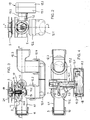
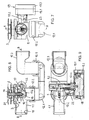
- Fig. 1 is a waste and overflow set for bathtubs, shower trays, sinks and sinks shown.
- Fig. 1 refers to both alternatives according to the invention.
- the clothing has a drain housing 1 with an inlet opening 2.
- the inlet opening 2 is surrounded by an annular groove or an annular shoulder 3 of the drain housing.
- an annular seal 4 is inserted, by means of which the drain body 1 can be waterproof fixed to a drain opening of a tub or a basin.
- On the inside of the tub or the basin a trough-shaped or bowl-shaped valve upper part 5 is arranged, in the bottom of a central mounting hole for receiving a screwed to the drain housing 1 hollow screw 6 is formed.
- the drain housing 1 is provided with an integrally formed nozzle 1.1 for connecting an overflow pipe 8.
- the connecting piece 1.1 has this in a conventional manner an external thread with a union nut 9 and a conically expanding to its end inner surface 10 as a clamping fit for a plugged onto the overflow pipe 8 sealing ring 11th
- the drain housing 1 is further provided with a smell trap 12, to which a drain pipe bend 13 can be connected.
- the odor trap 12 is formed from a substantially U-shaped channel 12.1, which at its inlet a latchable with the drain housing 1 cap 12.2 and at its outlet one with a Pipe elbow 12.3 latching cap 12.4, wherein the two latching connections on the one hand enable rotation of the U-shaped channel 12.1 relative to the drain body 1 and on the other hand rotate the pipe elbow 12.3 relative to the U-shaped channel 12.1 respectively about a substantially vertical axis.
- the valve upper part 5 is associated with a valve plug 14 as a valve body.
- the valve plug (valve body) 14 is provided with a valve stem 14.1, which is inserted into the hollow screw 6.
- the lower end of the valve stem 14.1 is provided with a threaded bore and a screw screwed therein (compensating or adjusting screw) 15.
- the screw 15 allows a length compensation of the valve stem 14.1 with respect to different wall thicknesses of the tub or pelvic floor.
- the varying wall thickness is in Fig. 3 indicated by the reference X.
- the Einstellnch, ie the adjustable length of the valve stem 14.1 including the screw 15 is in Fig. 5 denoted by the reference E.
- a length compensation can be done by omitting the screw 15 or by screwing a longer or shorter screw 15.
- the screw 15 with a lock nut 16 (in Fig. 5 not shown) (cf. Fig. 8 ).
- the lower end of the valve stem 14.1 or the head of the compensating or adjusting screw 15 is assigned a rotatably mounted in the drain housing lever mechanism 17 for actuating the valve body 14.
- the lever mechanism 17 comprises a drive shaft 17.1, with a hook-shaped lever 17.2 is positively connected and rotationally fixed.
- the bottom of the upper valve part 5 has a plurality of openings through which liquid can flow from the trough or the basin into the drain housing 1 when the valve body 14 is raised.
- the raised and lowered valve body 14 is shown in a raised position, although the lever 17.2 is shown in a lowered position.
- the lever mechanism 17 is coupled to an electric motor 18.
- the electric motor 18 is a stepper motor with a reversible direction of rotation.
- the electric motor 18 is arranged in a liquid-tight motor housing 19.
- the housing 19 is formed in two parts and mounted on the drain housing 1.
- a cup-shaped part 19.1 of the motor housing connected to the end of a hollow cylindrical or tubular part 1.2 of the drain housing 1.
- a hollow cylindrical connection piece 19.2 is formed for this purpose.
- the cup-shaped housing part 19.1 is provided with a removable housing cover 19.2.
- the drive shaft 17.1 of the lever mechanism is rotatably mounted.
- the motor-side end of the drive shaft 17.1 is formed as a four-sided or polygonal head 17.3 and positively connected to the output shaft of the motor 18.
- the motor 18 is arranged so that the rotation axis of the lever mechanism 17 and the output shaft of the motor 18 are substantially aligned with each other.
- an overload protection device is arranged in that the connected to the valve body 14 valve stem 14.1 is telescopically formed, wherein in the valve stem, a compression spring 20 acts as a force element.
- the valve stem 14.1 is formed of an outer tube 14.11 and an inner rod 14.12 inserted therein.
- the inner rod 14.12 has a radial projection 14.13 as a support surface for the lower end of the compression spring 20, while the outer tube 14.11 inside a projecting shoulder or constriction 14.14 which serves as a stop for the upper end of the compression spring 20.
- the outer tube 14.11 is fixedly connected to the plate-shaped part 14.2 of the valve body (valve plug) 14, preferably screwed.
- the plate-shaped part 14.2 has a circumferential shoulder 14.21 or annular groove, which carries a sealing ring 14.3.
- the outer tube 14.11 penetrates the dish-shaped part 14.2, wherein on the upper end of the tube a cover 21 is plugged or screwed.
- a cover 21 On the underside of the cover 21 web-shaped projections 21.1 are formed, the set in the assembled state of the cover 21, the sealing ring 14.3 on the shoulder 14.21 of the valve plate 14.2 or press on the shoulder 14.21.
- the outer tube 14.11 of the telescopic valve stem 14.1 is axially movably guided in the hollow screw 6, which connects the upper valve part 5 with the drain housing 1.
- the inner rod 14.12 of the valve stem 14.1 is at its upper End provided with a threaded hole into which a screw 14.15 is screwed.
- the diameter of the screw head 14.16 is greater than the diameter of the inner rod 14.12, so that the screw head 14.16 and the inwardly projecting shoulder (narrowing) 14.14 of the outer tube 14.11 form mutual stops.
- the screw head 14.16 is guided with play in the above the constriction 14.14 extending portion of the outer tube 14.11.
- the compression spring 20 is installed biased, so that no stroke for the valve body 14 is lost when you open the drain valve.
- the lever 17.2 presses the inner rod 14.12 against the force of the compression spring 20 upwards, wherein the inner rod 14.12 enters the outer tube 14.11.
- the valve body 14 can be pressed downwards, for example when a person steps on the cover 21 without the lever 17.2 having to move downwards, which would force a rotation of the drive shaft 17.1 or motor shaft. The mechanics and the motor 18 are therefore each reliably protected against overloading.
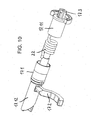
- the overload protection device is formed here of a torsion spring 22 which is arranged between the output shaft of the electric motor 18 and the rotatable lever 17.2.
- the lever 17.2 torsionally rigid carrying drive shaft 17.1 is divided between the motor 18 and lever 17.2, wherein the motor-side shaft portion 17.11 is torsionally connected via the torsion spring 22 with the separated shaft portion 17.12.
- the torsion spring 22 is received together with the split drive shaft 17.1 in the hollow cylindrical part 1.2 of the drain housing 1.
- the motor-side end of the drive shaft is in turn formed as a four-sided or polygonal head 17.3 and positively connected to the motor shaft. The motor shaft and the drive shaft are aligned.
- the valve stem 14.1 of the plate-shaped valve body 14 is in the embodiment according to Fig. 8 formed as a one-piece sleeve or rod having at its lower end an internal thread for a balance screw (adjusting screw) 15.
- the upper end of the rod or sleeve 14.1 penetrates the plate-shaped valve body 14.
- the valve body 14 and the valve top 5 are as in the in the FIGS. 2 to 6 shown executed.
- the torsion spring 22 ensures that only a predetermined torque is transmitted. Also, with the drain valve open, the valve body 14 can be pressed down, wherein the lever 17.2 at the same time dodges down and rotates the rotationally rigidly connected to him drive shaft section 17.12; however, the motor 18 does not have to yield due to the torsion spring 22. Thus, the mechanism 17 and the motor 18 are reliably protected against overload in this embodiment.
Landscapes
- Engineering & Computer Science (AREA)
- Mechanical Engineering (AREA)
- Environmental & Geological Engineering (AREA)
- Health & Medical Sciences (AREA)
- Life Sciences & Earth Sciences (AREA)
- Hydrology & Water Resources (AREA)
- Public Health (AREA)
- Water Supply & Treatment (AREA)
- Sink And Installation For Waste Water (AREA)
- Mechanically-Actuated Valves (AREA)
Claims (8)
- Dispositif d'écoulement et de trop-plein, en particulier pour baignoires ou lavabos, qui comprend un boitier d'écoulement (1), un corps de clapet (14) et un mécanisme de levier (17) rotatif, monté dans le boîtier d'écoulement pour l'actionnement du corps de clapet (14), sachant que le mécanisme de levier (17) est couplé avec un moteur électrique (18) et qu'un dispositif de protection contre les surcharges (20; 22) est prévu, caractérisé en ce que le dispositif de protection contre les surcharges (20; 22) est disposé dans la voie de transmission de force du moteur électrique (18) au corps de clapet (14), sachant que ledit dispositif de protection contre les surcharges (20; 22) est formé par un ressort de torsion (22), qui est disposé entre l'arbre de sortie du moteur électrique (18) et le levier (17.2) du mécanisme de levier (17), ou par un ressort de pression (20), qui est intégré dans une tige du clapet (14.1) de conception télescopique, reliée au corps de clapet (14).
- Dispositif d'écoulement et de trop-plein selon la revendication 1,
caractérisé en ce que le mécanisme de levier (17) est doté d'un arbre d'entraînement divisé (17.1), sachant qu'une section (17.11) de l'arbre d'entraînement, côté moteur, est couplée, élastique en rotation, par l'intermédiaire du ressort de torsion (22), avec une deuxième section (17.12) de l'arbre d'entraînement, dont un levier (17.2) fait saillie radialement. - Dispositif d'écoulement et de trop-plein selon revendication 1 ou 2,
caractérisé en ce que la tige du clapet (14.1) est formée par un tube extérieur (14.11) et une tige intérieure (14.12) qui est insérée dans celui-ci, sachant que la tige intérieure (14.12) est dotée d'une saillie radiale (14.13), qui sert de surface d'appui pour l'extrémité inférieure du ressort de pression (20), tandis que le tube extérieur (14.11) est doté, à l'intérieur, d'un étranglement (24.14), qui sert de butée pour l'extrémité supérieure du ressort de pression (20). - Dispositif d'écoulement et de trop-plein selon la revendication 3,
caractérisé en ce que la tige intérieure (14.12) est dotée, à son extrémité supérieure, d'un trou fileté et d'une vis (14.15) vissée dans celui-ci, sachant que le diamètre de la tête (14.16) de la vis est plus grand que le diamètre de la tige intérieure (14.12) et sachant que la tête (14.16) de la vis est guidée avec jeu dans la section du tube extérieur (14.11) qui s'étend au-dessus de l'étranglement (14.14). - Dispositif d'écoulement et de trop-plein selon l'une des revendications 3 ou 4,
caractérisé en ce que la tige intérieure (14.12) est dotée, à son extrémité inférieure, d'un trou fileté dans lequel est vissée une vis (15) pour une régulation de la longueur. - Dispositif d'écoulement et de trop-plein selon l'une des revendications 1 à 5,
caractérisé en ce que le ressort de pression (20) est monté précontraint. - Dispositif d'écoulement et de trop-plein selon l'une des revendications 1 à 6,
caractérisé en ce que le moteur électrique (1) est disposé dans un carter de moteur (19) qui est monté sur le boîtier d'écoulement (1). - Dispositif d'écoulement et de trop-plein selon l'une des revendications 1 à 7,
caractérisé en ce que l'axe de rotation du mécanisme de levier (17) et l'arbre de sortie du moteur électrique (18) sont sensiblement en alignement l'un par rapport à l'autre.
Applications Claiming Priority (1)
| Application Number | Priority Date | Filing Date | Title |
|---|---|---|---|
| DE200920015538 DE202009015538U1 (de) | 2009-11-17 | 2009-11-17 | Ab- und Überlaufgarnitur, insbesondere für Badewannen |
Publications (3)
| Publication Number | Publication Date |
|---|---|
| EP2322729A2 EP2322729A2 (fr) | 2011-05-18 |
| EP2322729A3 EP2322729A3 (fr) | 2012-10-10 |
| EP2322729B1 true EP2322729B1 (fr) | 2016-01-06 |
Family
ID=43607791
Family Applications (1)
| Application Number | Title | Priority Date | Filing Date |
|---|---|---|---|
| EP10189068.9A Active EP2322729B1 (fr) | 2009-11-17 | 2010-10-27 | Dispositif d'écoulement et de trop-plein, notamment pour baignoires |
Country Status (4)
| Country | Link |
|---|---|
| EP (1) | EP2322729B1 (fr) |
| DE (1) | DE202009015538U1 (fr) |
| DK (1) | DK2322729T3 (fr) |
| ES (1) | ES2565406T3 (fr) |
Families Citing this family (6)
| Publication number | Priority date | Publication date | Assignee | Title |
|---|---|---|---|---|
| US9260846B2 (en) | 2011-08-18 | 2016-02-16 | Kohler Co. | Drain control assembly |
| DE102013107824A1 (de) * | 2013-07-23 | 2015-01-29 | Duravit Aktiengesellschaft | Ablaufventil zum Einsetzen in eine Ablauföffnung eines WCs oder Urinals |
| DE202013012152U1 (de) * | 2013-11-05 | 2015-07-02 | Grohe Ag | Sanitärbecken mit elektrisch steuerbarem Antrieb für ein Schließelement |
| CN103603416B (zh) * | 2013-11-29 | 2015-04-29 | 桂林康兴医疗器械有限公司 | 一种可数字调控的排水装置 |
| DE102014103654A1 (de) * | 2014-03-18 | 2015-09-24 | Sonja Maria Bilz | Abfluss-Verschlussstopfen |
| AU2021202929B2 (en) * | 2020-05-13 | 2026-04-02 | Geberit International Ag | Drain arrangement |
Family Cites Families (7)
| Publication number | Priority date | Publication date | Assignee | Title |
|---|---|---|---|---|
| DE480935C (de) * | 1929-08-10 | Emma Schaefer | Bodenventil fuer Waschbecken, Badewannen u. dgl. mit einem durch den Druck des Beckeninhaltes gegen eine von zwei ineinanderschiebbaren Huelsen wasserdicht umschlossene Schraubenfeder absenkbaren Verschlusskoerper | |
| US2918999A (en) * | 1957-06-19 | 1959-12-29 | Television Associates Inc | Overload control |
| DE2813088A1 (de) * | 1978-03-25 | 1979-10-04 | Viegener Ii Fa Franz | Ablaufgarnitur eines sanitaereinrichtungsgegenstandes |
| DE3644480A1 (de) * | 1986-12-24 | 1988-07-07 | Grohe Kg Hans | Sanitaeres ablaufventil |
| FR2740793B1 (fr) * | 1995-11-03 | 1998-01-30 | Wirquin Plastiques Sa | Dispositif de commande de vidage d'appareils sanitaires |
| EP1703027B1 (fr) * | 2005-03-17 | 2016-08-24 | Geberit International AG | Dispositif pour activer le clapet d'écoulement d'articles sanitaires et en particulier une baignoire |
| DE202007012241U1 (de) * | 2007-08-31 | 2007-12-27 | Tg Kunststoffverarbeitung Gmbh | Excenterventil |
-
2009
- 2009-11-17 DE DE200920015538 patent/DE202009015538U1/de not_active Expired - Lifetime
-
2010
- 2010-10-27 DK DK10189068.9T patent/DK2322729T3/en active
- 2010-10-27 EP EP10189068.9A patent/EP2322729B1/fr active Active
- 2010-10-27 ES ES10189068.9T patent/ES2565406T3/es active Active
Also Published As
| Publication number | Publication date |
|---|---|
| ES2565406T3 (es) | 2016-04-04 |
| EP2322729A2 (fr) | 2011-05-18 |
| DK2322729T3 (en) | 2016-03-21 |
| DE202009015538U1 (de) | 2011-04-07 |
| EP2322729A3 (fr) | 2012-10-10 |
Similar Documents
| Publication | Publication Date | Title |
|---|---|---|
| EP2322729A2 (fr) | Dispositif d'écoulement et de trop-plein, notamment pour baignoires | |
| EP1612337B1 (fr) | Dispositif de trop-plein avec réglage continu de niveau pour une baignoire | |
| EP2108750A2 (fr) | Armature d'écoulement pour baignoire ou de bac de douche dotés d'une alimentation au sol | |
| DE2806382A1 (de) | Ueberlaufventil | |
| EP1703027B1 (fr) | Dispositif pour activer le clapet d'écoulement d'articles sanitaires et en particulier une baignoire | |
| EP1813732B1 (fr) | Rosette rotative destinée à l'actionnement d'un clapet de sortie d'un dispositif d'écoulement ou de trop-plein d'une baignoire | |
| EP3354808B1 (fr) | Garniture d'évacuation pourvue de bouchon de vidange pouvant être soulevé et abaissé | |
| EP2090813A2 (fr) | Armature sanitaire antigel | |
| EP1447486B1 (fr) | Bouche d'écoulement | |
| EP2406529B1 (fr) | Melangeur a levier unique pour un robinet d'eau | |
| DE102007009409A1 (de) | Armatur mit Schwenkauslauf | |
| DE10222932C1 (de) | Waschbeckenarmatur | |
| EP2119837B1 (fr) | Garniture d'écoulement pour lavabos ou éviers | |
| EP4043651B1 (fr) | Armature sanitaire dotée d'un élément actionneur | |
| EP2767638B1 (fr) | Armature d'écoulement et de trop-plein avec régulateur de jet pour baignoires | |
| EP3165141B1 (fr) | Ferrure de fixation d'une porte | |
| EP3783158B1 (fr) | Armature d'écoulement et de trop-plein pour une baignoire | |
| EP2775047B1 (fr) | Armature d'écoulement et de trop-plein pour baignoire | |
| DE2723010C3 (de) | Ab- und Überlaufeinrichtung an Bade- und Duschwannen | |
| EP1493873B1 (fr) | Soupape de vidange avec servomoteur | |
| DE10316372B3 (de) | Sanitäres Mischventil | |
| EP1013837A2 (fr) | Bonde pour baignoire | |
| DE202015009268U1 (de) | Armatur, insbesondere für ein Küchen- oder Badmöbel | |
| DE202004001093U1 (de) | Regulier- und Absperrarmatur | |
| EP4323594B1 (fr) | Adaptateur pour dispositif de drainage |
Legal Events
| Date | Code | Title | Description |
|---|---|---|---|
| PUAI | Public reference made under article 153(3) epc to a published international application that has entered the european phase |
Free format text: ORIGINAL CODE: 0009012 |
|
| AK | Designated contracting states |
Kind code of ref document: A2 Designated state(s): AL AT BE BG CH CY CZ DE DK EE ES FI FR GB GR HR HU IE IS IT LI LT LU LV MC MK MT NL NO PL PT RO RS SE SI SK SM TR |
|
| AX | Request for extension of the european patent |
Extension state: BA ME |
|
| PUAL | Search report despatched |
Free format text: ORIGINAL CODE: 0009013 |
|
| AK | Designated contracting states |
Kind code of ref document: A3 Designated state(s): AL AT BE BG CH CY CZ DE DK EE ES FI FR GB GR HR HU IE IS IT LI LT LU LV MC MK MT NL NO PL PT RO RS SE SI SK SM TR |
|
| AX | Request for extension of the european patent |
Extension state: BA ME |
|
| RIC1 | Information provided on ipc code assigned before grant |
Ipc: E03C 1/23 20060101AFI20120831BHEP |
|
| 17P | Request for examination filed |
Effective date: 20121116 |
|
| GRAP | Despatch of communication of intention to grant a patent |
Free format text: ORIGINAL CODE: EPIDOSNIGR1 |
|
| INTG | Intention to grant announced |
Effective date: 20150717 |
|
| GRAS | Grant fee paid |
Free format text: ORIGINAL CODE: EPIDOSNIGR3 |
|
| GRAA | (expected) grant |
Free format text: ORIGINAL CODE: 0009210 |
|
| RAP1 | Party data changed (applicant data changed or rights of an application transferred) |
Owner name: VIEGA GMBH & CO. KG |
|
| AK | Designated contracting states |
Kind code of ref document: B1 Designated state(s): AL AT BE BG CH CY CZ DE DK EE ES FI FR GB GR HR HU IE IS IT LI LT LU LV MC MK MT NL NO PL PT RO RS SE SI SK SM TR |
|
| REG | Reference to a national code |
Ref country code: GB Ref legal event code: FG4D Free format text: NOT ENGLISH |
|
| REG | Reference to a national code |
Ref country code: CH Ref legal event code: EP |
|
| REG | Reference to a national code |
Ref country code: IE Ref legal event code: FG4D Free format text: LANGUAGE OF EP DOCUMENT: GERMAN |
|
| REG | Reference to a national code |
Ref country code: AT Ref legal event code: REF Ref document number: 768988 Country of ref document: AT Kind code of ref document: T Effective date: 20160215 |
|
| REG | Reference to a national code |
Ref country code: DE Ref legal event code: R096 Ref document number: 502010010868 Country of ref document: DE |
|
| REG | Reference to a national code |
Ref country code: CH Ref legal event code: NV Representative=s name: SCHMAUDER AND PARTNER AG PATENT- UND MARKENANW, CH |
|
| REG | Reference to a national code |
Ref country code: DK Ref legal event code: T3 Effective date: 20160318 |
|
| REG | Reference to a national code |
Ref country code: ES Ref legal event code: FG2A Ref document number: 2565406 Country of ref document: ES Kind code of ref document: T3 Effective date: 20160404 |
|
| REG | Reference to a national code |
Ref country code: NL Ref legal event code: FP |
|
| REG | Reference to a national code |
Ref country code: LT Ref legal event code: MG4D |
|
| PG25 | Lapsed in a contracting state [announced via postgrant information from national office to epo] |
Ref country code: FI Free format text: LAPSE BECAUSE OF FAILURE TO SUBMIT A TRANSLATION OF THE DESCRIPTION OR TO PAY THE FEE WITHIN THE PRESCRIBED TIME-LIMIT Effective date: 20160106 Ref country code: GR Free format text: LAPSE BECAUSE OF FAILURE TO SUBMIT A TRANSLATION OF THE DESCRIPTION OR TO PAY THE FEE WITHIN THE PRESCRIBED TIME-LIMIT Effective date: 20160407 Ref country code: NO Free format text: LAPSE BECAUSE OF FAILURE TO SUBMIT A TRANSLATION OF THE DESCRIPTION OR TO PAY THE FEE WITHIN THE PRESCRIBED TIME-LIMIT Effective date: 20160406 Ref country code: HR Free format text: LAPSE BECAUSE OF FAILURE TO SUBMIT A TRANSLATION OF THE DESCRIPTION OR TO PAY THE FEE WITHIN THE PRESCRIBED TIME-LIMIT Effective date: 20160106 |
|
| PG25 | Lapsed in a contracting state [announced via postgrant information from national office to epo] |
Ref country code: LV Free format text: LAPSE BECAUSE OF FAILURE TO SUBMIT A TRANSLATION OF THE DESCRIPTION OR TO PAY THE FEE WITHIN THE PRESCRIBED TIME-LIMIT Effective date: 20160106 Ref country code: LT Free format text: LAPSE BECAUSE OF FAILURE TO SUBMIT A TRANSLATION OF THE DESCRIPTION OR TO PAY THE FEE WITHIN THE PRESCRIBED TIME-LIMIT Effective date: 20160106 Ref country code: PL Free format text: LAPSE BECAUSE OF FAILURE TO SUBMIT A TRANSLATION OF THE DESCRIPTION OR TO PAY THE FEE WITHIN THE PRESCRIBED TIME-LIMIT Effective date: 20160106 Ref country code: PT Free format text: LAPSE BECAUSE OF FAILURE TO SUBMIT A TRANSLATION OF THE DESCRIPTION OR TO PAY THE FEE WITHIN THE PRESCRIBED TIME-LIMIT Effective date: 20160506 Ref country code: SE Free format text: LAPSE BECAUSE OF FAILURE TO SUBMIT A TRANSLATION OF THE DESCRIPTION OR TO PAY THE FEE WITHIN THE PRESCRIBED TIME-LIMIT Effective date: 20160106 Ref country code: IS Free format text: LAPSE BECAUSE OF FAILURE TO SUBMIT A TRANSLATION OF THE DESCRIPTION OR TO PAY THE FEE WITHIN THE PRESCRIBED TIME-LIMIT Effective date: 20160506 Ref country code: RS Free format text: LAPSE BECAUSE OF FAILURE TO SUBMIT A TRANSLATION OF THE DESCRIPTION OR TO PAY THE FEE WITHIN THE PRESCRIBED TIME-LIMIT Effective date: 20160106 |
|
| REG | Reference to a national code |
Ref country code: DE Ref legal event code: R097 Ref document number: 502010010868 Country of ref document: DE |
|
| REG | Reference to a national code |
Ref country code: FR Ref legal event code: PLFP Year of fee payment: 7 |
|
| PG25 | Lapsed in a contracting state [announced via postgrant information from national office to epo] |
Ref country code: EE Free format text: LAPSE BECAUSE OF FAILURE TO SUBMIT A TRANSLATION OF THE DESCRIPTION OR TO PAY THE FEE WITHIN THE PRESCRIBED TIME-LIMIT Effective date: 20160106 |
|
| PLBE | No opposition filed within time limit |
Free format text: ORIGINAL CODE: 0009261 |
|
| STAA | Information on the status of an ep patent application or granted ep patent |
Free format text: STATUS: NO OPPOSITION FILED WITHIN TIME LIMIT |
|
| PG25 | Lapsed in a contracting state [announced via postgrant information from national office to epo] |
Ref country code: CZ Free format text: LAPSE BECAUSE OF FAILURE TO SUBMIT A TRANSLATION OF THE DESCRIPTION OR TO PAY THE FEE WITHIN THE PRESCRIBED TIME-LIMIT Effective date: 20160106 Ref country code: SK Free format text: LAPSE BECAUSE OF FAILURE TO SUBMIT A TRANSLATION OF THE DESCRIPTION OR TO PAY THE FEE WITHIN THE PRESCRIBED TIME-LIMIT Effective date: 20160106 Ref country code: SM Free format text: LAPSE BECAUSE OF FAILURE TO SUBMIT A TRANSLATION OF THE DESCRIPTION OR TO PAY THE FEE WITHIN THE PRESCRIBED TIME-LIMIT Effective date: 20160106 Ref country code: RO Free format text: LAPSE BECAUSE OF FAILURE TO SUBMIT A TRANSLATION OF THE DESCRIPTION OR TO PAY THE FEE WITHIN THE PRESCRIBED TIME-LIMIT Effective date: 20160106 |
|
| 26N | No opposition filed |
Effective date: 20161007 |
|
| PG25 | Lapsed in a contracting state [announced via postgrant information from national office to epo] |
Ref country code: BE Free format text: LAPSE BECAUSE OF NON-PAYMENT OF DUE FEES Effective date: 20161031 Ref country code: BG Free format text: LAPSE BECAUSE OF FAILURE TO SUBMIT A TRANSLATION OF THE DESCRIPTION OR TO PAY THE FEE WITHIN THE PRESCRIBED TIME-LIMIT Effective date: 20160406 Ref country code: SI Free format text: LAPSE BECAUSE OF FAILURE TO SUBMIT A TRANSLATION OF THE DESCRIPTION OR TO PAY THE FEE WITHIN THE PRESCRIBED TIME-LIMIT Effective date: 20160106 |
|
| REG | Reference to a national code |
Ref country code: CH Ref legal event code: PUE Owner name: VIEGA TECHNOLOGY GMBH AND CO. KG, DE Free format text: FORMER OWNER: VIEGA GMBH AND CO. KG, DE |
|
| REG | Reference to a national code |
Ref country code: DE Ref legal event code: R082 Ref document number: 502010010868 Country of ref document: DE Representative=s name: COHAUSZ & FLORACK PATENT- UND RECHTSANWAELTE P, DE Ref country code: DE Ref legal event code: R081 Ref document number: 502010010868 Country of ref document: DE Owner name: VIEGA TECHNOLOGY GMBH & CO. KG, DE Free format text: FORMER OWNER: VIEGA GMBH & CO. KG, 57439 ATTENDORN, DE |
|
| REG | Reference to a national code |
Ref country code: AT Ref legal event code: PC Ref document number: 768988 Country of ref document: AT Kind code of ref document: T Owner name: VIEGA TECHNOLOGY GMBH & CO. KG, DE Effective date: 20170512 |
|
| REG | Reference to a national code |
Ref country code: NL Ref legal event code: PD Owner name: VIEGA TECHNOLOGY GMBH & CO. KG; DE Free format text: DETAILS ASSIGNMENT: CHANGE OF OWNER(S), ASSIGNMENT; FORMER OWNER NAME: VIEGA GMBH & CO. KG Effective date: 20170412 |
|
| REG | Reference to a national code |
Ref country code: IE Ref legal event code: MM4A |
|
| REG | Reference to a national code |
Ref country code: GB Ref legal event code: 732E Free format text: REGISTERED BETWEEN 20170706 AND 20170715 |
|
| PG25 | Lapsed in a contracting state [announced via postgrant information from national office to epo] |
Ref country code: LU Free format text: LAPSE BECAUSE OF NON-PAYMENT OF DUE FEES Effective date: 20161027 |
|
| REG | Reference to a national code |
Ref country code: ES Ref legal event code: PC2A Owner name: VIEGA TECHNOLOGY GMBH & CO. KG Effective date: 20170925 |
|
| REG | Reference to a national code |
Ref country code: FR Ref legal event code: PLFP Year of fee payment: 8 |
|
| REG | Reference to a national code |
Ref country code: FR Ref legal event code: TP Owner name: VIEGA TECHNOLOGY GMBH & CO. KG, DE Effective date: 20171013 |
|
| PG25 | Lapsed in a contracting state [announced via postgrant information from national office to epo] |
Ref country code: IE Free format text: LAPSE BECAUSE OF NON-PAYMENT OF DUE FEES Effective date: 20161027 |
|
| REG | Reference to a national code |
Ref country code: BE Ref legal event code: MM Effective date: 20161031 |
|
| PG25 | Lapsed in a contracting state [announced via postgrant information from national office to epo] |
Ref country code: HU Free format text: LAPSE BECAUSE OF FAILURE TO SUBMIT A TRANSLATION OF THE DESCRIPTION OR TO PAY THE FEE WITHIN THE PRESCRIBED TIME-LIMIT; INVALID AB INITIO Effective date: 20101027 Ref country code: CY Free format text: LAPSE BECAUSE OF FAILURE TO SUBMIT A TRANSLATION OF THE DESCRIPTION OR TO PAY THE FEE WITHIN THE PRESCRIBED TIME-LIMIT Effective date: 20160106 |
|
| PG25 | Lapsed in a contracting state [announced via postgrant information from national office to epo] |
Ref country code: MK Free format text: LAPSE BECAUSE OF FAILURE TO SUBMIT A TRANSLATION OF THE DESCRIPTION OR TO PAY THE FEE WITHIN THE PRESCRIBED TIME-LIMIT Effective date: 20160106 Ref country code: TR Free format text: LAPSE BECAUSE OF FAILURE TO SUBMIT A TRANSLATION OF THE DESCRIPTION OR TO PAY THE FEE WITHIN THE PRESCRIBED TIME-LIMIT Effective date: 20160106 Ref country code: MT Free format text: LAPSE BECAUSE OF FAILURE TO SUBMIT A TRANSLATION OF THE DESCRIPTION OR TO PAY THE FEE WITHIN THE PRESCRIBED TIME-LIMIT Effective date: 20160106 Ref country code: MC Free format text: LAPSE BECAUSE OF FAILURE TO SUBMIT A TRANSLATION OF THE DESCRIPTION OR TO PAY THE FEE WITHIN THE PRESCRIBED TIME-LIMIT Effective date: 20160106 |
|
| REG | Reference to a national code |
Ref country code: FR Ref legal event code: PLFP Year of fee payment: 9 |
|
| PG25 | Lapsed in a contracting state [announced via postgrant information from national office to epo] |
Ref country code: AL Free format text: LAPSE BECAUSE OF FAILURE TO SUBMIT A TRANSLATION OF THE DESCRIPTION OR TO PAY THE FEE WITHIN THE PRESCRIBED TIME-LIMIT Effective date: 20160106 |
|
| PGFP | Annual fee paid to national office [announced via postgrant information from national office to epo] |
Ref country code: NL Payment date: 20211020 Year of fee payment: 12 |
|
| PGFP | Annual fee paid to national office [announced via postgrant information from national office to epo] |
Ref country code: ES Payment date: 20211119 Year of fee payment: 12 Ref country code: DK Payment date: 20211019 Year of fee payment: 12 Ref country code: GB Payment date: 20211014 Year of fee payment: 12 |
|
| PGFP | Annual fee paid to national office [announced via postgrant information from national office to epo] |
Ref country code: IT Payment date: 20211026 Year of fee payment: 12 Ref country code: FR Payment date: 20211014 Year of fee payment: 12 |
|
| PGFP | Annual fee paid to national office [announced via postgrant information from national office to epo] |
Ref country code: AT Payment date: 20221025 Year of fee payment: 13 |
|
| REG | Reference to a national code |
Ref country code: DK Ref legal event code: EBP Effective date: 20221031 |
|
| REG | Reference to a national code |
Ref country code: NL Ref legal event code: MM Effective date: 20221101 |
|
| GBPC | Gb: european patent ceased through non-payment of renewal fee |
Effective date: 20221027 |
|
| PG25 | Lapsed in a contracting state [announced via postgrant information from national office to epo] |
Ref country code: NL Free format text: LAPSE BECAUSE OF NON-PAYMENT OF DUE FEES Effective date: 20221101 Ref country code: FR Free format text: LAPSE BECAUSE OF NON-PAYMENT OF DUE FEES Effective date: 20221031 |
|
| PG25 | Lapsed in a contracting state [announced via postgrant information from national office to epo] |
Ref country code: IT Free format text: LAPSE BECAUSE OF NON-PAYMENT OF DUE FEES Effective date: 20221027 Ref country code: GB Free format text: LAPSE BECAUSE OF NON-PAYMENT OF DUE FEES Effective date: 20221027 Ref country code: DK Free format text: LAPSE BECAUSE OF NON-PAYMENT OF DUE FEES Effective date: 20221031 |
|
| REG | Reference to a national code |
Ref country code: ES Ref legal event code: FD2A Effective date: 20231201 |
|
| PG25 | Lapsed in a contracting state [announced via postgrant information from national office to epo] |
Ref country code: ES Free format text: LAPSE BECAUSE OF NON-PAYMENT OF DUE FEES Effective date: 20221028 |
|
| PG25 | Lapsed in a contracting state [announced via postgrant information from national office to epo] |
Ref country code: ES Free format text: LAPSE BECAUSE OF NON-PAYMENT OF DUE FEES Effective date: 20221028 |
|
| REG | Reference to a national code |
Ref country code: AT Ref legal event code: MM01 Ref document number: 768988 Country of ref document: AT Kind code of ref document: T Effective date: 20231027 |
|
| PG25 | Lapsed in a contracting state [announced via postgrant information from national office to epo] |
Ref country code: AT Free format text: LAPSE BECAUSE OF NON-PAYMENT OF DUE FEES Effective date: 20231027 |
|
| PG25 | Lapsed in a contracting state [announced via postgrant information from national office to epo] |
Ref country code: AT Free format text: LAPSE BECAUSE OF NON-PAYMENT OF DUE FEES Effective date: 20231027 |
|
| REG | Reference to a national code |
Ref country code: CH Ref legal event code: U11 Free format text: ST27 STATUS EVENT CODE: U-0-0-U10-U11 (AS PROVIDED BY THE NATIONAL OFFICE) Effective date: 20251101 |
|
| PGFP | Annual fee paid to national office [announced via postgrant information from national office to epo] |
Ref country code: DE Payment date: 20251021 Year of fee payment: 16 |
|
| PGFP | Annual fee paid to national office [announced via postgrant information from national office to epo] |
Ref country code: CH Payment date: 20251101 Year of fee payment: 16 |