EP3783158B1 - Armature d'écoulement et de trop-plein pour une baignoire - Google Patents
Armature d'écoulement et de trop-plein pour une baignoire Download PDFInfo
- Publication number
- EP3783158B1 EP3783158B1 EP20184223.4A EP20184223A EP3783158B1 EP 3783158 B1 EP3783158 B1 EP 3783158B1 EP 20184223 A EP20184223 A EP 20184223A EP 3783158 B1 EP3783158 B1 EP 3783158B1
- Authority
- EP
- European Patent Office
- Prior art keywords
- drain
- overflow
- housing
- guide
- bolt
- Prior art date
- Legal status (The legal status is an assumption and is not a legal conclusion. Google has not performed a legal analysis and makes no representation as to the accuracy of the status listed.)
- Active
Links
Images



Classifications
-
- E—FIXED CONSTRUCTIONS
- E03—WATER SUPPLY; SEWERAGE
- E03C—DOMESTIC PLUMBING INSTALLATIONS FOR FRESH WATER OR WASTE WATER; SINKS
- E03C1/00—Domestic plumbing installations for fresh water or waste water; Sinks
- E03C1/12—Plumbing installations for waste water; Basins or fountains connected thereto; Sinks
- E03C1/22—Outlet devices mounted in basins, baths, or sinks
- E03C1/23—Outlet devices mounted in basins, baths, or sinks with mechanical closure mechanisms
- E03C1/2304—Outlet devices mounted in basins, baths, or sinks with mechanical closure mechanisms the actuation force being transmitted to the plug via flexible elements, e.g. chain, Bowden cable
-
- E—FIXED CONSTRUCTIONS
- E03—WATER SUPPLY; SEWERAGE
- E03C—DOMESTIC PLUMBING INSTALLATIONS FOR FRESH WATER OR WASTE WATER; SINKS
- E03C1/00—Domestic plumbing installations for fresh water or waste water; Sinks
- E03C1/12—Plumbing installations for waste water; Basins or fountains connected thereto; Sinks
- E03C1/22—Outlet devices mounted in basins, baths, or sinks
- E03C1/23—Outlet devices mounted in basins, baths, or sinks with mechanical closure mechanisms
- E03C1/232—Outlet devices mounted in basins, baths, or sinks with mechanical closure mechanisms combined with overflow devices
Definitions
- the invention relates to a drain and overflow fitting for a bathtub according to the preamble of claim 1.
- the EN 10 2006 053 756 A1 discloses a drain fitting for showers or bathtubs, the housing of which has an interior space accessible from the inlet opening, which is delimited by boundary walls connected in one piece with the housing.
- a water guide is designed as a drainage channel, which leads from a base of the housing first upwards and then in a U-shaped curve a little way downwards and then horizontally outwards.
- the housing part containing the water guide is shaped in such a way that the water guide always has a rectangular cross-section when viewed in the direction of flow.
- the water guide is sealed liquid-tight by a separately manufactured front cover. The cover is welded to the housing part containing the water guide.
- a transition piece is welded to the end of the water guide, which serves to connect the water guide, which has a rectangular cross-section, to a pipe with a circular cross-section.
- the transition piece represents the actual drain connection of the housing.
- the housing of this drain fitting is therefore made up of three parts.
- Low sanitary drain fittings are often required for the construction and renovation of bathrooms.
- Conventional drain fittings for showers and/or bathtubs do offer a drainage capacity that complies with standards, but due to their height they cannot usually meet the special requirements for a flat design for low installation spaces.
- shower and bathtub drains can sometimes be difficult to clean if they are blocked by hair. or other deposits are blocked.
- Cleaning drain fittings is often only possible with increased effort, for example by dismantling dip pipes or plugs to enable or facilitate the insertion of cleaning spirals or other cleaning tools.
- the EN 10 2006 053 756 A1 Although the well-known drain fitting offers a relatively high drainage capacity, due to its height it is not suitable or not at all suitable for use under bathtubs with a low installation height. In addition, due to its narrow water flow, this drain fitting can only be cleaned with increased effort in the event of a blockage.
- a drain and overflow fitting of the type mentioned above is known, for example, under the name "Rotaplex".
- the drain and overflow fitting has a pivoting lever for raising and lowering the drain valve body.
- the lever is hook-shaped. It is attached to a shaft that is rotatably mounted in the drain housing.
- the shaft is provided with a second, radially protruding lever to which one end of a Bowden cable is connected.
- the other end of the Bowden cable is connected to an actuating mechanism with a rotating rosette that is mounted on an overflow opening in the tub wall.
- the "Rotaplex" drain and overflow fitting has proven itself very well in practice. Nevertheless, this drain and overflow fitting still appears to be in need of improvement in terms of its cleaning options and reduced susceptibility to dirt.
- a device for operating the drain valve of a bathtub has a housing that can be attached to the bathtub and in which a push button for operating the drain valve is mounted.
- a pull element connects the push button to a closure body that is slidably mounted in a housing of the drain valve.
- a switching device is mounted on the housing of the drain valve and can be switched to open and close the drain valve by pulling.
- the DE 27 55 414 B1 discloses a device for operating the valve cone of a bathtub drain valve that can be raised and lowered, in which a rotary handle arranged away from the drain valve is coupled to a rotary device to which the cable of a Bowden cable is eccentrically anchored, the other end of which is attached to a sliding piece arranged in a horizontal guide tube that is aligned radially to the cylindrical drain valve housing.
- the sliding piece is connected to a pivoting lever mounted in the drain valve housing, on which the valve cone sits loosely.
- the pivoting lever is hinged to the sliding piece at one end and has a guide surface on the underside that acts as an inclined plane and rests on the lower edge of the mouth of the guide tube in the drain valve housing, via which it can be partially pulled into the guide tube by the sliding piece while performing a vertical pivoting movement.
- the drain valve housing is designed in two parts and has an upper housing part. The valve cone is guided so that it can move freely axially by means of a central pin in a spoke hub in the upper housing part.
- the EP 3 461 958 A1 discloses a drainage device that allows water to be drained from a cleaning basin without having to reach into the water in the cleaning basin with one hand.
- the drainage device comprises a downpipe, a connecting rod arranged in the downpipe and guided vertically therein, a connecting seat with a waste water connection and a valve cover for closing or opening the waste water connection.
- the valve cover is connected to an upper end of the connecting rod.
- a fastening seat is arranged on a side wall of the downpipe, to which a mounting housing is fastened.
- a sliding piece is slidably arranged in the mounting housing, with a bevelled end section for supporting the connecting rod being arranged on the end of the sliding piece facing the connecting rod.
- US$ 1,974,419 discloses a drain valve with a substantially spherical valve body which is rotatable about a rotation axis extending transversely to the longitudinal axis of the cavity of the valve housing.
- the valve body has a through opening and a flattened section with a circumferential bevel which seals against the valve seat when the drain valve is closed.
- the US 8 336 132 B2 discloses a drain actuation system for a bathtub that includes a cable for actuating a raising and lowering valve body of a drain. More specifically, one end of the cable is connected to the drain without additional moving parts, and another end of the cable is connected to an overflow cap of an overflow system, wherein rotation of the overflow cap selectively moves the cable to move the valve body of the drain.
- the present invention is based on the object of creating a drain and overflow fitting of the type mentioned at the outset, which allows a relatively simple cleaning, in particular of the overflow connection, if necessary and is less susceptible to contamination.
- a drain and overflow fitting for a bathtub comprising a drain housing which has an inlet opening, at least one overflow connection and a laterally projecting drain channel, wherein the drain channel defines an odor trap and a drain connection is arranged at the end of the drain channel, wherein a raising and lowering drain valve body and a drain valve mechanism are integrated in the drain housing, and wherein the drain valve mechanism has a force transmission means for lifting the drain valve body, wherein the drain housing has a first guide in which the force transmission means is displaceably guided, wherein the force transmission means interacts with a vertically movable bolt in such a way that the bolt is raised or lowered when the force transmission means is displaced, and wherein the bolt is connected to the drain valve body or interacts with the drain valve body, wherein the drain housing has a second guide in which the Bolt is guided so as to be vertically displaceable, wherein the second guide has a sleeve-shaped section for receiving the bolt,
- the first guide and the second guide are thus fixed inside the drain housing without or almost without a retaining web. This completely or largely avoids retaining webs that would prevent or disrupt the formation of a flow-optimized inner contour of the drain housing.
- the invention enables a particularly reliable valve mechanism with a flow-optimized drain contour at the same time.
- the valve mechanism of the drain and overflow fitting according to the invention does not require the pivoting lever mentioned above, which is susceptible to deposits of hair and other dirt.
- the (first) guide for the valve mechanism of the drain and overflow fitting according to the invention can be arranged, for example, on the bottom of the drain housing, so that the at least one overflow connection of the drain housing is easily and simply accessible for cleaning purposes after dismantling the drain valve body.
- the drain housing, in particular the drain channel and/or the overflow connection can be cleaned, for example, using a cleaning spiral.
- the force transmission means of the drain and overflow fitting has an inclined or curved support track on which the vertically movable bolt is supported in such a way that it is raised when the force transmission means is displaced. or lowered.
- This makes it possible to achieve a valve mechanism that requires relatively low actuation forces to raise the drain valve body or to open the drain valve.
- the support track is concave. This means that at the beginning of the drain valve opening, when the force required is at its maximum due to the water column pressing on the drain valve body, the actuation force applied can be used optimally to open the drain valve. After overcoming the initial resistance when opening the drain valve, the actuation force applied is then translated by means of the concave support track in such a way that the drain valve body is lifted off at an accelerated rate.
- the (first) guide is designed such that the force transmission means is guided therein in a linearly displaceable manner.
- the guide can thus be implemented in a cost-effective manner and offers a high level of functional reliability.
- the first guide has a base whose underside is flush with the underside or a support surface of the drain housing.
- This design contributes to reducing the installation height of the drain and overflow fitting.
- the installation height of the drain and overflow fitting according to the invention below the bathtub can, for example, be only about 80 mm. This allows the installation height of a bathtub equipped with the drain and overflow fitting to be reduced accordingly.
- a further advantageous embodiment of the invention is characterized in that the drain housing has two or three overflow connections.
- the drain housing can be designed without the swivel joint that is usually found in conventional drain and overflow fittings for bathtubs and is arranged below the overflow connection.
- an optimized drain flow can be achieved.
- the installation height of the drain and overflow fitting can be significantly reduced.
- the two or three overflow connections mean that the drain and overflow fitting according to the invention can be variably mounted on the bathtub in question even without the joint mentioned, ie despite the elimination of the joint.
- the overflow connection(s) of the drain and overflow fitting that are not required are or will be closed.
- blind plugs are provided, for example, which can be connected to the overflow connections in a liquid-tight and detachable manner, for example by screwing.
- the overflow connections are arranged in such a way that their central axes intersect the bolt or a valve stem of the drain valve body. This facilitates good accessibility of the overflow connections and easy installation of an overflow line and the blind plugs on the overflow connections.
- the upper end of the second guide is lower than the central axis of the at least one overflow connection. This allows very good accessibility of the overflow connection after dismantling the drain valve body for any cleaning of the overflow connection that may be necessary.
- the upper end of the second guide is spaced vertically downwards from the horizontal center axis of the overflow connection by a distance which corresponds to at least 1/10, preferably at least 1/5 of the inner diameter of the overflow connection.
- the second guide for receiving the bolt is sleeve-shaped.
- a further advantageous embodiment of the invention provides that the drain housing has a valve seat for the drain valve body located below the inlet opening, wherein the valve seat defines a drain opening whose inner diameter is at least 2/3, preferably at least 3/4 of the inner diameter of the inlet opening. This allows a relatively large access opening to be achieved for any cleaning that may be necessary inside the drain housing, in particular the drain channel and the overflow connection.
- the bolt is provided with at least one ring seal on its outer circumference. This enables a reliable seal between the valve mechanism and the interior of the drain housing to be achieved in a cost-effective manner.
- a further advantageous embodiment of the invention is characterized in that the drain housing has a drainage surface facing the inlet opening and running at an angle in the direction of the drainage channel. This embodiment promotes a high drainage capacity of the drain and overflow fitting, improves the reliability of the odor trap and makes it easier to insert a cleaning spiral into the drainage channel.
- a further advantageous embodiment of the invention is characterized in that the drain housing has a drainage surface facing the inlet opening and running at an angle in the direction of the drainage channel. This embodiment promotes a high drainage capacity of the drain and overflow fitting, improves the reliability of the odor trap and makes it easier to insert a cleaning spiral into the drainage channel.
- the drainage channel is wave-shaped and has a channel section defining an overflow edge, whereby the overflow edge is located above the central axis of the overflow connection, i.e. higher than this central axis, in the functional position of the drainage and overflow fitting.
- This embodiment enables the installation height of the drainage and overflow fitting to be reduced in the case of high or standard-compliant drainage performance.
- a further advantageous embodiment of the invention provides that the wave-shaped channel section, viewed in longitudinal section, has a concave bottom section whose arc radius is greater than the overall height of the drain housing.
- This embodiment in particular the relatively large arc radius of the concave bottom section, makes it even easier to insert a cleaning spiral into the wave-shaped drain channel.
- the wave-shaped channel section viewed in longitudinal section, has a convex bottom section which extends at least to the overflow edge and whose arc radius is greater than half the overall height of the drain housing.
- This embodiment also contributes to the easy insertion of a cleaning spiral into the wave-shaped drain channel.
- a further embodiment of the invention provides that the drain housing of the drain and overflow fitting is composed of a lower housing part and an upper housing part, whereby the lower housing part and the upper housing part are connected to one another in a liquid-tight manner by a circumferential connecting seam, and whereby the connecting seam runs along opposite long sides of the wave-shaped channel section of the drain channel.
- the housing parts can be made from plastic by injection molding, for example.
- the circumferential connecting seam between the lower housing part and the upper housing part is preferably designed as a weld seam.
- a further embodiment of the invention is that the drain connection is preferably designed as a drain nozzle with a circular cross-section and is formed in one piece with the lower housing part.
- the drain housing of the drain fitting according to the invention can thus be composed of essentially only two housing parts.
- the drain and overflow fitting according to the invention is thus characterized by a small number of components. This embodiment reduces the manufacturing costs and the risk of leaky connection points, in particular leaky weld seams.
- a further advantageous embodiment of the invention is that the width of the drainage channel decreases in the direction of water drainage between the overflow edge and the drainage connection, preferably the drainage nozzle.
- the width of the drainage channel thus tapers from or after the overflow edge in the direction of the drainage connection. This avoids steps or edges that could interfere with the insertion of a cleaning spiral into the drainage connection or drainage nozzle and a drainage pipe connected to it.
- the wave-shaped drain channel or channel section preferably has a substantially uniform width (internal width) from its beginning below the inlet opening to the overflow edge. This allows the available space under a bathtub to be used ideally.
- the width of the drain channel measured orthogonally to the channel base area increases after the overflow edge in the direction of the drain connection.
- the drain and overflow fitting 1 shown in the drawing is intended for installation on a bathtub that has a floor drain opening and an overflow opening in its side wall.
- the drain and overflow fitting 1 is particularly suitable for bathtubs that, when installed, offer little space under the tub floor for the arrangement of a drain housing to be attached to the floor drain opening.
- the edge area of the tub bottom surrounding the floor drain opening usually protrudes downwards from the underside of the tub bottom, with a conical bottom section merging continuously into a substantially horizontal bottom section which delimits the floor drain opening.
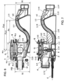
- the drain and overflow fitting 1 has a drain housing 2 with an inlet opening 3 and a laterally protruding drain channel 2.1, at the end of which a drain connection 2.2 is arranged.
- the drain connection 2.2 is preferably designed in the form of a drain nozzle for connecting a drain pipe with a circular cross-section.
- the drain connection 2.2 has an external thread onto which a union nut is screwed.
- the drain pipe for example a pipe bend, is inserted into the drain connection (drain nozzle) 2.2 and connected to it in a liquid-tight manner by means of the union nut with the interposition of a sealing ring.
- a drain valve body 4 that can be raised and lowered and a drain valve mechanism are integrated in the drain housing 2.
- the drain housing has a valve seat located below the inlet opening 3, wherein the valve seat defines a drain opening 30, the inner diameter of which is at least 2/3, preferably at least 3/4 of the inner diameter of the inlet opening 3.
- the drain valve mechanism has a force transmission means 5.
- the force transmission means 5 is preferably coupled to a Bowden cable 6, the other end 6.1 of which is connected to an actuating mechanism (not shown).
- the drain housing 2 has a (first) guide 2.3 in which the force transmission means 5 is guided in a displaceable manner.
- the guide 2.3 is preferably designed such that the force transmission means 5 is guided in a linearly displaceable manner therein.
- the force transmission means 5 can also be referred to as a slide or linear slide.
- the force transmission means 5 cooperates with a vertically movable bolt 7, in such a way that the bolt 7 is raised or lowered when the force transmission means 5 is moved, whereby the bolt 7 is connected to the drain valve body 4 or cooperates with it.
- the bolt 7 is detachably connected to the valve stem 4.1 of the drain valve body 4, for example by a screw connection.
- the bolt 7 can have a bore with an internal thread at its upper end, for example, into which the lower end of the valve stem 4.1 is detachably screwed with a corresponding external thread.
- Fig.4 the directions of movement for raising or lowering the bolt 7 and the drain valve body 4 on the one hand and the displacement directions of the force transmission means 5 on the other hand are marked by vertical and horizontal arrows.
- the force transmission means 5 defines a curved support path (movement path) 8, on which the vertically movable bolt 7 is supported in such a way that it is raised or lowered when the force transmission means 5 is moved.
- the support path 8 is preferably concave for this purpose (cf. Fig.4 ).
- the force transmission means 5 has, for example, two legs or flanges 5.1, 5.2, which delimit a vertical gap 5.3, which is open at least at the top, into which the bolt 7 engages from above, preferably with a slight amount of play.
- curved, preferably concave grooves or slots 9 are formed, into which at the lower end of the Bolt 7 engages radially projecting guide pins 7.1.
- the opposing guide pins 7.1 can be defined, for example, by a pin that is inserted into a transverse bore of the bolt 7 and has a length that is significantly greater than the outer diameter of the bolt section located between the legs or flanges 5.1, 5.2.
- the grooves or slots 9 each define a curved or concave support track 8 for the guide pins 7.1 fixed to the bolt.
- the grooves or slots 9 have closed ends, so that the movement of the guide pins 7.1 along the parallel support tracks 8 is limited.
- the force transmission means 5 has a connection section 5.4 on one end face for coupling the Bowden cable 6.
- the connection section 5.4 is, for example, groove-shaped or trough-shaped and has a crossbar or an undercut to which a head-shaped end of the Bowden cable 6 can be connected or hooked in a form-fitting manner.
- FIG.8 The embodiment shown differs from that shown in the Figures 4 and 7 shown embodiment only with regard to the design of the power transmission means 5.
- the in the drain and overflow fitting according to Fig.8 The force transmission means 5 used has an inclined support track 8 instead of a curved or concave support track 8.
- the inclined, essentially straight support track 8 can also be referred to as an inclined surface.
- the guide 2.3 receiving the force transmission means 5 has a base 2.31, the underside of which is flush with the underside or support surface 2.4 of the drain housing 2.
- the base 2.31 of the guide 2.3 is integrally integrated into the base of the drain housing 2.
- the drain housing 2 has a second guide 2.5, in which the bolt 7 is guided so as to be vertically displaceable (cf. Fig.5 , 7 and 8th ).
- the drain housing 2 does not have a joint with a vertical axis of rotation below the drain valve body 4. Rather, the base body of the drain housing 2 is essentially designed to be torsionally rigid. In order to be able to mount the drain housing 2 variably on the bathtub in question depending on the installation situation, it has three overflow connections 2.7.
- the overflow connections 2.7 are designed in the shape of a pipe socket and are arranged on the essentially pot-shaped section 2.6 of the drain housing 2.
- Each of the overflow connections 2.7 has an external thread 2.71 onto which a union nut 11 is screwed.
- An overflow line 12, preferably an overflow pipe, is connected to one of the three overflow connections 2.7, the upper end of which is connected to an overflow body (not shown).
- the overflow body is provided with the actuating mechanism, for example a rotary rosette, for opening and closing the drain valve integrated in the drain housing 2 and is mounted on an overflow opening which is arranged below the upper edge of the bathtub in the tub wall.
- the Bowden cable 6 for operating the drain valve is connected to the actuating mechanism of the overflow body.
- blind plugs 13 are provided, which can be inserted into the relevant overflow connections 2.7 and connected to them in a liquid-tight manner.
- the respective blind plug 13 is connected to the relevant overflow connection 2.7 in a liquid-tight manner by means of the union nut 11 with the interposition of a sealing ring.
- the blind plugs 13 can, for example, be designed in the form of a circular cylindrical sleeve with a closed base.
- the pipe socket-shaped overflow connections 2.7 are arranged on the drain housing 2 in such a way that their central axes MH the bolt 7 or the valve stem 4.1 of the Drain valve body 4.
- the upper end of the guide 2.5 is lower than the central axis MH of the respective overflow connection 2.7.
- the guide 2.5 is sleeve-shaped or has a sleeve-shaped section for receiving the bolt 7, wherein the sleeve-shaped section projects upwards relative to the lowest point 2.72 of the inner surface of the respective overflow connection 2.7 and is fastened with its lower end to the guide 2.3 receiving the force transmission means 5.
- the upper end of the guide 2.5 is spaced downwards from the horizontal central axis MH of the respective overflow connection 2.7 by a vertical dimension which corresponds to at least 1/10, preferably at least 1/5 of the inner diameter of the overflow connection 2.7.
- the bolt 7 On its outer circumference, the bolt 7 is provided with one or more ring seals 10, which rest sealingly and slidably on the inside of the sleeve-shaped guide 2.5, so that the lower guide 2.3 of the power transmission means 5 is sealed against the ingress of water.
- the bolt is provided with ring grooves into which the ring seals (O-rings) 10 are inserted.
- the drain channel 2.1 defines an odor trap.
- the drain channel 2.1 has a wave-shaped channel section 2.11 defining an overflow edge 2.9.
- the overflow edge 2.9 is higher than the essentially horizontal center axis MH of the respective overflow connection 2.7, with a lower edge 2.10 of the housing inner wall limiting the inlet opening of the drain channel 2.1 at the top.
- the sealing water height of the drain housing 2 is, for example, approx. 50 mm.
- a conical fastening ring 16 is assigned to the inlet opening 3.
- the fastening ring 16 is arranged on the inside of the bathtub and is preferably made of stainless steel. It has holes that allow the shafts of Fastening screws 18 are used.
- the inner housing wall 2.61 defining the inlet opening 3 is essentially circular-cylindrical or has three circular-arc-shaped wall sections 2.62, these wall sections 2.62 being integrally connected to one another via radially inwardly projecting, essentially vertically running wall sections 2.63.
- the wall areas 2.63 are aligned with wall sections 2.64 which project radially from the outside of the drain housing 2 and which also run essentially vertically.
- threaded sleeves are introduced into the housing wall, into which the fastening screws 18 are or are screwed.
- three metal threaded sleeves are integrated in the drain housing 2 made of plastic, for example polypropylene, the threaded sleeves being evenly spaced from one another.
- the drain housing 2 is provided with an annular seal 14 which surrounds the inlet opening 3 and has a sealing surface 14.1 intended to rest on the underside of the tub floor.
- the seal 14 rests sealingly on the underside of the tub floor section which delimits the floor drain opening.
- the seal 14 has an axial section 14.2 and two flange-shaped sections 14.3, 14.4 which project radially outwards from it, with the lower section 14.3 intended to rest on the underside of the bathtub and the upper section 14.4 intended to rest on the inside of the bathtub.
- the wave-shaped discharge channel 2.1 is designed in such a way that it has as few changes in direction and cross-section as possible.
- the shortest horizontal distance A K of the highest The distance A K between the highest point of the overflow edge 2.9 and the circumferential inner surface of the inlet opening 3 is comparatively large.
- the shortest horizontal distance A K between the highest point of the overflow edge 2.9 and the circumferential inner surface of the inlet opening 3 is, for example, at least 0.9 times, preferably at least 1.1 times, the horizontal inner width D of the inlet opening 3.
- the inlet opening 3 is essentially circular-cylindrical.
- a shortest horizontal distance A KM of the highest point of the overflow edge of the drain and overflow fitting 1 can also be defined in relation to the vertical center axis MV of the inlet opening 3.
- the shortest horizontal distance A KM of the highest point of the overflow edge 2.9 from the center axis MV of the inlet opening 3 is more than 1.8 times, for example approximately twice, the inner diameter or the smallest horizontal inner width D of the inlet opening 3.
- the wave-shaped drainage channel 2.1 viewed in longitudinal section, has a concave bottom section 2.12 in the area between the inlet opening 3 and the overflow edge 2.9, the arc radius of which is greater than the construction height H1 of the drainage housing 2 (see Figures 6 and 7 ).
- the concave bottom section 2.12 is adjoined, as viewed in the longitudinal section of the drain channel 2.1, by a convexly shaped channel bottom section 2.13 which extends at least as far as the overflow edge 2.9 or beyond, wherein the arc radius of the convex bottom section 2.13 is greater than half the overall height H1 of the drain housing 2.
- the drainage channel 2.1 Along its length, starting from the inlet opening 3 up to the overflow edge 2.9, the drainage channel 2.1 has a substantially constant width B or inner width as well as a substantially constant width W1, the latter being measured orthogonally to the undulating channel base area (see Figures 5 and 7 ).
- the width B of the drainage channel 2.1 In the water drainage direction, which is Fig.6 marked by simple arrows, the width B of the drainage channel 2.1 after the overflow edge 2.9 in towards the drain connection 2.2.
- the width B of the drain channel 2.1 thus tapers after the overflow edge 2.9 in the direction of the drain nozzle.
- the width W2 of the drain channel 2.1 measured orthogonally to the channel base area increases, so that the inner cross-sectional area of the drain channel 2.1 changes little or only slightly along the channel center line between the overflow edge 2.9 and the drain nozzle 2.2.
- the drain housing 2 is composed of a housing lower part 2.15 and a housing upper part 2.16, which are connected to one another in a liquid-tight manner by a circumferential connecting seam 2.17, preferably a weld seam.
- the connecting seam 2.17 runs along the opposite long sides of the wave-shaped channel section of the drain channel 2.1.
- the connecting seam 2.17 On the front side of the drain housing 2 opposite the drain connection 2.2, the connecting seam 2.17 has a semicircular arc-shaped seam section, while it is designed to be contour-parallel along the long sides of the wave-shaped drain channel 2.1 and thus also has a wave-shaped course on both long sides.
- At least one stiffening rib 2.18, 2.19 is provided on the underside of the lower housing part 2.15 and on the top of the upper housing part 2.16, which is formed in one piece with the lower housing part 2.15 or the upper housing part 2.16.
- the floor surface 2.20 of the housing interior facing the inlet opening 3 is inclined in the direction of the drainage channel 2.1.
- the gradient of this floor surface 2.20 namely its angle of inclination relative to the horizontal, is for example in the range of 12° to 18°, in particular in the range of 14° to 16°.
- the channel bottom section 2.22 following the overflow edge 2.9 in the direction of water drainage has a steep gradient and is designed in sections as a steep inclined surface 2.23 or inclined plane.
- the angle of inclination of the inclined surface 2.23 relative to the horizontal is, for example, in the range of 70° to 80°.
- the distance A SM of the end of the drain connection (drain nozzle) 2.2 from the central axis MV of the inlet opening 3 is more than 220 mm.
- the distance H2 of the sealing surface 14.1 intended to rest on the underside of the tub bottom from the housing underside of the drain and overflow fitting shown is less than 80 mm, preferably less than 75 mm, in the installed state.
Landscapes
- Engineering & Computer Science (AREA)
- Mechanical Engineering (AREA)
- Environmental & Geological Engineering (AREA)
- Health & Medical Sciences (AREA)
- Life Sciences & Earth Sciences (AREA)
- Hydrology & Water Resources (AREA)
- Public Health (AREA)
- Water Supply & Treatment (AREA)
- Sink And Installation For Waste Water (AREA)
Claims (13)
- Armature d'écoulement et de trop-plein (1) pour une baignoire,avec un corps d'écoulement (2) présentant un orifice d'entrée (3), au moins un raccord de trop-plein (2.7) et un canal d'écoulement (2.1) faisant saillie latéralement,dans laquelle le canal d'écoulement définit un bouchon anti-odeur, et un raccord d'écoulement (2.2) est agencé à l'extrémité du canal d'écoulement (2.1),dans laquelle un corps de vanne d'écoulement (4) pouvant être soulevé et abaissé et un mécanisme de vanne d'écoulement sont intégrés dans le corps d'écoulement (2), etdans laquelle le mécanisme de vanne d'écoulement présente un moyen de transmission de force (5) afin de soulever le corps de vanne d'écoulement (4),dans laquelle le corps d'écoulement (2) présente un premier guide (2.3) au sein duquel le moyen de transmission de force (5) est guidé de manière à pouvoir coulisser,dans laquelle le moyen de transmission de force (5) collabore avec un boulon (7) mobile verticalement de telle manière que le boulon (7) est soulevé ou abaissé lors du coulissement du moyen de transmission de force (5), etdans laquelle le boulon (7) est relié au corps de vanne d'écoulement (4) ou collabore avec le corps de vanne d'écoulement (4), dans laquellele corps d'écoulement (2) présente un second guide (2.5) au sein duquel le boulon (7) est guidé de manière à pouvoir coulisser verticalement, dans laquellele second guide (2.5) présente une section en forme de manchon afin d'accueillir le boulon (7), caractérisée en ce que la section en forme de manchon fait saillie vers le haut par rapport au point le plus profond de la surface intérieure du raccord de trop-plein (2.7) et est fixée par son extrémité inférieure au premier guide (2.3),et dans laquelle le moyen de transmission de force (5) présente un chemin de support (8) oblique ou incurvé sur lequel l'axe (7) mobile verticalement est supporté de telle manière que le boulon (7) est soulevé ou abaissé lors du coulissement du moyen de transmission de force (5).
- Armature d'écoulement et de trop-plein selon la revendication 1,
caractérisée en ce que le chemin de support (8) est concave. - Armature d'écoulement et de trop-plein selon la revendication 1 ou 2,
caractérisée en ce que le premier guide (2.3) est réalisé de telle manière que le moyen de transmission de force (5) y est guidé de manière à pouvoir coulisser linéairement. - Armature d'écoulement et de trop plein selon l'une quelconque des revendications 1 à 3, caractérisée en ce que le premier guide (2.3) présente un fond dont la face inférieure est réalisé de manière à se trouver à ras de la face inférieure ou d'une surface d'appui (2.4) du corps d'écoulement (2),
- Armature d'écoulement et de trop plein selon l'une quelconque des revendications 1 à 4, caractérisée en ce que le corps d'écoulement (2) présente deux ou trois raccords de trop-plein (2.7).
- Armature d'écoulement et de trop-plein selon la revendication 5,
caractérisée en ce que les raccords de trop-plein (2.7) sont agencés de telle manière que leurs axes centraux (MH) coupent le boulon (7) ou une tige de vanne (4.1) du corps de vanne d'écoulement (4). - Armature d'écoulement et de trop plein selon l'une quelconque des revendications 1 à 6, caractérisée en ce que l'extrémité supérieure du second guide (2.5) est plus basse que l'axe central (MH) du au moins un raccord de trop-plein (2.7).
- Armature d'écoulement et de trop plein selon l'une quelconque des revendications 1 à 7, caractérisée en ce que l'extrémité supérieure du second guide (2.5) est espacée verticalement vers le bas par rapport à l'axe central horizontal (MH) du raccord de trop-plein (2.7) dans une proportion correspondant à au moins 1/10, de manière préférée à au moins 1/5 du diamètre intérieur du raccord de trop-plein (2.7).
- Armature d'écoulement et de trop plein selon l'une quelconque des revendications 1 à 8, caractérisée en ce que le second guide (2.5) est réalisé en forme de manchon afin d'accueillir le boulon (7).
- Armature d'écoulement et de trop plein selon l'une quelconque des revendications 1 à 9, caractérisée en ce que le corps d'écoulement (2) présente un siège de vanne situé au-dessous de l'orifice d'entrée (3) et destiné au corps de vanne d'écoulement (4), dans laquelle le siège de vanne définit une orifice d'écoulement (30) dont le diamètre intérieur représente au moins 2/3, de manière préférée au moins 3/4 du diamètre intérieur de l'orifice d'entrée (3).
- Armature d'écoulement et de trop plein selon l'une quelconque des revendications 1 à 10, caractérisée en ce que le boulon (7) est muni d'un joint annulaire (10) sur sa périphérie extérieure.
- Armature d'écoulement et de trop plein selon l'une quelconque des revendications 1 à 11, caractérisée en ce que le corps d'écoulement (2) présente une surface d'écoulement (2.20) orientée vers l'orifice d'entrée (3) et inclinée dans la direction du canal d'écoulement (2.1).
- Armature d'écoulement et de trop plein selon l'une quelconque des revendications 1 à 12, caractérisée en ce que le canal d'écoulement (2.1) est ondulé et présente une section de canal (2.11) définissant un bord de trop-plein (2.9), dans laquelle le bord de trop-plein (2.9) se trouve au-dessus de l'axe central (MH) du raccord de trop-plein (2.7) en position fonctionnelle par rapport à l'armature d'écoulement et de trop-plein (1).
Applications Claiming Priority (1)
| Application Number | Priority Date | Filing Date | Title |
|---|---|---|---|
| DE202019104582.5U DE202019104582U1 (de) | 2019-08-21 | 2019-08-21 | Ab- und Überlaufarmatur für eine Badewanne |
Publications (2)
| Publication Number | Publication Date |
|---|---|
| EP3783158A1 EP3783158A1 (fr) | 2021-02-24 |
| EP3783158B1 true EP3783158B1 (fr) | 2024-06-26 |
Family
ID=71515066
Family Applications (1)
| Application Number | Title | Priority Date | Filing Date |
|---|---|---|---|
| EP20184223.4A Active EP3783158B1 (fr) | 2019-08-21 | 2020-07-06 | Armature d'écoulement et de trop-plein pour une baignoire |
Country Status (2)
| Country | Link |
|---|---|
| EP (1) | EP3783158B1 (fr) |
| DE (1) | DE202019104582U1 (fr) |
Families Citing this family (1)
| Publication number | Priority date | Publication date | Assignee | Title |
|---|---|---|---|---|
| CN116616664A (zh) * | 2023-05-25 | 2023-08-22 | 火星人厨具股份有限公司 | 一种下水装置及清洗机 |
Citations (1)
| Publication number | Priority date | Publication date | Assignee | Title |
|---|---|---|---|---|
| US8336132B2 (en) * | 2008-08-18 | 2012-12-25 | Wcm Industries, Inc. | Cable actuated drain |
Family Cites Families (13)
| Publication number | Priority date | Publication date | Assignee | Title |
|---|---|---|---|---|
| US1974419A (en) * | 1932-11-22 | 1934-09-25 | Jr Edward S Cornell | Stop and discharge valve |
| GB450411A (en) * | 1935-01-16 | 1936-07-16 | Butzke Bernhard Joseph A G F | Improvements in or relating to waste and overflow devices for liquid containers, such as baths, wash-basins, bidets and the like |
| US2245946A (en) * | 1939-06-21 | 1941-06-17 | Edward A Vermere | Waste system |
| US2880425A (en) * | 1955-10-13 | 1959-04-07 | Scovill Manufacturing Co | Drain apparatus |
| US3002196A (en) * | 1959-09-29 | 1961-10-03 | Scovill Manufacturing Co | Pop-up drain valve |
| DE2755414C2 (de) * | 1977-12-13 | 1979-11-22 | Hans Grohe Gmbh & Co Kg, 7622 Schiltach | Vorrichtung zur Betätigung des heb- und senkbaren Ventilkegels eines Wannenablaufventils |
| DE3334010A1 (de) * | 1983-09-21 | 1985-04-04 | Viegener II, Franz, 5952 Attendorn | Drehgriffarmatur zur fernbetaetigung von zwei oder mehreren ablaufventilen in spueltischen, waschtischen o.dgl. |
| US4577349A (en) * | 1985-05-28 | 1986-03-25 | Clegg John E | Sink outlet valve |
| DE102005011790B3 (de) * | 2005-03-11 | 2006-11-23 | Franz Kaldewei Gmbh & Co Kg | Sanitärwanne |
| DE202006006240U1 (de) * | 2005-11-24 | 2006-12-07 | Desch, Kurt Michael, Dipl.-Ing. (FH) | Horizontale Badewannen-Überlaufgarnitur mit flexibel anordbarer Stopfen-Betätigung |
| EP1870527B1 (fr) * | 2006-06-20 | 2017-05-31 | Geberit International AG | Dispositif pour activer le clapet d'écoulement d'articles sanitaires. |
| DE102006053756A1 (de) * | 2006-11-13 | 2008-05-15 | Hansgrohe Ag | Ablaufarmatur |
| CN107653942B (zh) * | 2017-09-29 | 2024-07-16 | 浙江德利福科技股份有限公司 | 去水器 |
-
2019
- 2019-08-21 DE DE202019104582.5U patent/DE202019104582U1/de active Active
-
2020
- 2020-07-06 EP EP20184223.4A patent/EP3783158B1/fr active Active
Patent Citations (1)
| Publication number | Priority date | Publication date | Assignee | Title |
|---|---|---|---|---|
| US8336132B2 (en) * | 2008-08-18 | 2012-12-25 | Wcm Industries, Inc. | Cable actuated drain |
Also Published As
| Publication number | Publication date |
|---|---|
| DE202019104582U1 (de) | 2020-11-30 |
| EP3783158A1 (fr) | 2021-02-24 |
Similar Documents
| Publication | Publication Date | Title |
|---|---|---|
| EP2840191A1 (fr) | Dispositif de siphon | |
| EP2045403A1 (fr) | Garniture d'ecoulement avec trop-plein intégré | |
| DE69721255T2 (de) | Ferngesteuerter stöpsel | |
| EP3567170B1 (fr) | Dispositif d'évacuation pour une douche ou une baignoire | |
| EP3783158B1 (fr) | Armature d'écoulement et de trop-plein pour une baignoire | |
| EP2157247B1 (fr) | Bouche d'écoulement | |
| EP1707692B1 (fr) | Robinet pourvu d'un bec téléscopique | |
| EP3400342B1 (fr) | Robinetterie à soupape servant à remplir un réservoir de chasse sanitaire et réservoir de chasse sanitaire muni de ladite robinetterie à soupape | |
| DE3110151C2 (de) | Vorrichtung zum Betätigen eines heb- und senkbaren Ventilkegels eines Wannenablaufventils | |
| EP3354808B1 (fr) | Garniture d'évacuation pourvue de bouchon de vidange pouvant être soulevé et abaissé | |
| EP1870526A1 (fr) | Robinet sanitaire | |
| DE102005009777B4 (de) | Rückstauverschluss | |
| EP1217130A1 (fr) | Dispositif de fixation pour des parties de robinetterie sanitaire | |
| DE202015107000U1 (de) | Ablaufsystem | |
| EP2119837B1 (fr) | Garniture d'écoulement pour lavabos ou éviers | |
| EP3647504B1 (fr) | Dispositif formant article sanitaire | |
| EP2767638B1 (fr) | Armature d'écoulement et de trop-plein avec régulateur de jet pour baignoires | |
| DE102011013349A1 (de) | Ablaufvorrichtung für Abwasser | |
| EP3569777B1 (fr) | Système de support sanitaire | |
| EP4063574B1 (fr) | Ensemble lavabo | |
| EP3708724A1 (fr) | Dispositif d'écoulement avec trop-plein | |
| EP2997199B1 (fr) | Siphon pour trop-plein de lavabo | |
| EP1659323A1 (fr) | Vanne pour robinetterie sanitaire | |
| EP2921596B1 (fr) | Soupape de vidange | |
| EP4056776B1 (fr) | Agencement d'articles sanitaires |
Legal Events
| Date | Code | Title | Description |
|---|---|---|---|
| PUAI | Public reference made under article 153(3) epc to a published international application that has entered the european phase |
Free format text: ORIGINAL CODE: 0009012 |
|
| STAA | Information on the status of an ep patent application or granted ep patent |
Free format text: STATUS: THE APPLICATION HAS BEEN PUBLISHED |
|
| AK | Designated contracting states |
Kind code of ref document: A1 Designated state(s): AL AT BE BG CH CY CZ DE DK EE ES FI FR GB GR HR HU IE IS IT LI LT LU LV MC MK MT NL NO PL PT RO RS SE SI SK SM TR |
|
| AX | Request for extension of the european patent |
Extension state: BA ME |
|
| STAA | Information on the status of an ep patent application or granted ep patent |
Free format text: STATUS: REQUEST FOR EXAMINATION WAS MADE |
|
| 17P | Request for examination filed |
Effective date: 20210824 |
|
| RBV | Designated contracting states (corrected) |
Designated state(s): AL AT BE BG CH CY CZ DE DK EE ES FI FR GB GR HR HU IE IS IT LI LT LU LV MC MK MT NL NO PL PT RO RS SE SI SK SM TR |
|
| STAA | Information on the status of an ep patent application or granted ep patent |
Free format text: STATUS: EXAMINATION IS IN PROGRESS |
|
| 17Q | First examination report despatched |
Effective date: 20230102 |
|
| GRAP | Despatch of communication of intention to grant a patent |
Free format text: ORIGINAL CODE: EPIDOSNIGR1 |
|
| STAA | Information on the status of an ep patent application or granted ep patent |
Free format text: STATUS: GRANT OF PATENT IS INTENDED |
|
| INTG | Intention to grant announced |
Effective date: 20240315 |
|
| GRAS | Grant fee paid |
Free format text: ORIGINAL CODE: EPIDOSNIGR3 |
|
| GRAA | (expected) grant |
Free format text: ORIGINAL CODE: 0009210 |
|
| STAA | Information on the status of an ep patent application or granted ep patent |
Free format text: STATUS: THE PATENT HAS BEEN GRANTED |
|
| AK | Designated contracting states |
Kind code of ref document: B1 Designated state(s): AL AT BE BG CH CY CZ DE DK EE ES FI FR GB GR HR HU IE IS IT LI LT LU LV MC MK MT NL NO PL PT RO RS SE SI SK SM TR |
|
| REG | Reference to a national code |
Ref country code: GB Ref legal event code: FG4D Free format text: NOT ENGLISH |
|
| REG | Reference to a national code |
Ref country code: CH Ref legal event code: EP |
|
| REG | Reference to a national code |
Ref country code: DE Ref legal event code: R096 Ref document number: 502020008348 Country of ref document: DE |
|
| PG25 | Lapsed in a contracting state [announced via postgrant information from national office to epo] |
Ref country code: BG Free format text: LAPSE BECAUSE OF FAILURE TO SUBMIT A TRANSLATION OF THE DESCRIPTION OR TO PAY THE FEE WITHIN THE PRESCRIBED TIME-LIMIT Effective date: 20240626 |
|
| PG25 | Lapsed in a contracting state [announced via postgrant information from national office to epo] |
Ref country code: FI Free format text: LAPSE BECAUSE OF FAILURE TO SUBMIT A TRANSLATION OF THE DESCRIPTION OR TO PAY THE FEE WITHIN THE PRESCRIBED TIME-LIMIT Effective date: 20240626 Ref country code: HR Free format text: LAPSE BECAUSE OF FAILURE TO SUBMIT A TRANSLATION OF THE DESCRIPTION OR TO PAY THE FEE WITHIN THE PRESCRIBED TIME-LIMIT Effective date: 20240626 |
|
| REG | Reference to a national code |
Ref country code: LT Ref legal event code: MG9D |
|
| PG25 | Lapsed in a contracting state [announced via postgrant information from national office to epo] |
Ref country code: GR Free format text: LAPSE BECAUSE OF FAILURE TO SUBMIT A TRANSLATION OF THE DESCRIPTION OR TO PAY THE FEE WITHIN THE PRESCRIBED TIME-LIMIT Effective date: 20240927 |
|
| PG25 | Lapsed in a contracting state [announced via postgrant information from national office to epo] |
Ref country code: LV Free format text: LAPSE BECAUSE OF FAILURE TO SUBMIT A TRANSLATION OF THE DESCRIPTION OR TO PAY THE FEE WITHIN THE PRESCRIBED TIME-LIMIT Effective date: 20240626 |
|
| REG | Reference to a national code |
Ref country code: NL Ref legal event code: MP Effective date: 20240626 |
|
| PG25 | Lapsed in a contracting state [announced via postgrant information from national office to epo] |
Ref country code: NO Free format text: LAPSE BECAUSE OF FAILURE TO SUBMIT A TRANSLATION OF THE DESCRIPTION OR TO PAY THE FEE WITHIN THE PRESCRIBED TIME-LIMIT Effective date: 20240926 Ref country code: LV Free format text: LAPSE BECAUSE OF FAILURE TO SUBMIT A TRANSLATION OF THE DESCRIPTION OR TO PAY THE FEE WITHIN THE PRESCRIBED TIME-LIMIT Effective date: 20240626 Ref country code: HR Free format text: LAPSE BECAUSE OF FAILURE TO SUBMIT A TRANSLATION OF THE DESCRIPTION OR TO PAY THE FEE WITHIN THE PRESCRIBED TIME-LIMIT Effective date: 20240626 Ref country code: GR Free format text: LAPSE BECAUSE OF FAILURE TO SUBMIT A TRANSLATION OF THE DESCRIPTION OR TO PAY THE FEE WITHIN THE PRESCRIBED TIME-LIMIT Effective date: 20240927 Ref country code: FI Free format text: LAPSE BECAUSE OF FAILURE TO SUBMIT A TRANSLATION OF THE DESCRIPTION OR TO PAY THE FEE WITHIN THE PRESCRIBED TIME-LIMIT Effective date: 20240626 Ref country code: BG Free format text: LAPSE BECAUSE OF FAILURE TO SUBMIT A TRANSLATION OF THE DESCRIPTION OR TO PAY THE FEE WITHIN THE PRESCRIBED TIME-LIMIT Effective date: 20240626 Ref country code: RS Free format text: LAPSE BECAUSE OF FAILURE TO SUBMIT A TRANSLATION OF THE DESCRIPTION OR TO PAY THE FEE WITHIN THE PRESCRIBED TIME-LIMIT Effective date: 20240926 |
|
| PG25 | Lapsed in a contracting state [announced via postgrant information from national office to epo] |
Ref country code: NL Free format text: LAPSE BECAUSE OF FAILURE TO SUBMIT A TRANSLATION OF THE DESCRIPTION OR TO PAY THE FEE WITHIN THE PRESCRIBED TIME-LIMIT Effective date: 20240626 |
|
| PG25 | Lapsed in a contracting state [announced via postgrant information from national office to epo] |
Ref country code: NL Free format text: LAPSE BECAUSE OF FAILURE TO SUBMIT A TRANSLATION OF THE DESCRIPTION OR TO PAY THE FEE WITHIN THE PRESCRIBED TIME-LIMIT Effective date: 20240626 |
|
| PG25 | Lapsed in a contracting state [announced via postgrant information from national office to epo] |
Ref country code: PT Free format text: LAPSE BECAUSE OF FAILURE TO SUBMIT A TRANSLATION OF THE DESCRIPTION OR TO PAY THE FEE WITHIN THE PRESCRIBED TIME-LIMIT Effective date: 20241028 |
|
| PG25 | Lapsed in a contracting state [announced via postgrant information from national office to epo] |
Ref country code: PT Free format text: LAPSE BECAUSE OF FAILURE TO SUBMIT A TRANSLATION OF THE DESCRIPTION OR TO PAY THE FEE WITHIN THE PRESCRIBED TIME-LIMIT Effective date: 20241028 |
|
| PG25 | Lapsed in a contracting state [announced via postgrant information from national office to epo] |
Ref country code: PL Free format text: LAPSE BECAUSE OF FAILURE TO SUBMIT A TRANSLATION OF THE DESCRIPTION OR TO PAY THE FEE WITHIN THE PRESCRIBED TIME-LIMIT Effective date: 20240626 |
|
| PG25 | Lapsed in a contracting state [announced via postgrant information from national office to epo] |
Ref country code: EE Free format text: LAPSE BECAUSE OF FAILURE TO SUBMIT A TRANSLATION OF THE DESCRIPTION OR TO PAY THE FEE WITHIN THE PRESCRIBED TIME-LIMIT Effective date: 20240626 |
|
| PG25 | Lapsed in a contracting state [announced via postgrant information from national office to epo] |
Ref country code: IS Free format text: LAPSE BECAUSE OF FAILURE TO SUBMIT A TRANSLATION OF THE DESCRIPTION OR TO PAY THE FEE WITHIN THE PRESCRIBED TIME-LIMIT Effective date: 20241026 |
|
| PG25 | Lapsed in a contracting state [announced via postgrant information from national office to epo] |
Ref country code: CZ Free format text: LAPSE BECAUSE OF FAILURE TO SUBMIT A TRANSLATION OF THE DESCRIPTION OR TO PAY THE FEE WITHIN THE PRESCRIBED TIME-LIMIT Effective date: 20240626 |
|
| PG25 | Lapsed in a contracting state [announced via postgrant information from national office to epo] |
Ref country code: SK Free format text: LAPSE BECAUSE OF FAILURE TO SUBMIT A TRANSLATION OF THE DESCRIPTION OR TO PAY THE FEE WITHIN THE PRESCRIBED TIME-LIMIT Effective date: 20240626 Ref country code: RO Free format text: LAPSE BECAUSE OF FAILURE TO SUBMIT A TRANSLATION OF THE DESCRIPTION OR TO PAY THE FEE WITHIN THE PRESCRIBED TIME-LIMIT Effective date: 20240626 |
|
| PG25 | Lapsed in a contracting state [announced via postgrant information from national office to epo] |
Ref country code: SM Free format text: LAPSE BECAUSE OF FAILURE TO SUBMIT A TRANSLATION OF THE DESCRIPTION OR TO PAY THE FEE WITHIN THE PRESCRIBED TIME-LIMIT Effective date: 20240626 Ref country code: ES Free format text: LAPSE BECAUSE OF FAILURE TO SUBMIT A TRANSLATION OF THE DESCRIPTION OR TO PAY THE FEE WITHIN THE PRESCRIBED TIME-LIMIT Effective date: 20240626 |
|
| PG25 | Lapsed in a contracting state [announced via postgrant information from national office to epo] |
Ref country code: SM Free format text: LAPSE BECAUSE OF FAILURE TO SUBMIT A TRANSLATION OF THE DESCRIPTION OR TO PAY THE FEE WITHIN THE PRESCRIBED TIME-LIMIT Effective date: 20240626 Ref country code: SK Free format text: LAPSE BECAUSE OF FAILURE TO SUBMIT A TRANSLATION OF THE DESCRIPTION OR TO PAY THE FEE WITHIN THE PRESCRIBED TIME-LIMIT Effective date: 20240626 Ref country code: RO Free format text: LAPSE BECAUSE OF FAILURE TO SUBMIT A TRANSLATION OF THE DESCRIPTION OR TO PAY THE FEE WITHIN THE PRESCRIBED TIME-LIMIT Effective date: 20240626 Ref country code: PL Free format text: LAPSE BECAUSE OF FAILURE TO SUBMIT A TRANSLATION OF THE DESCRIPTION OR TO PAY THE FEE WITHIN THE PRESCRIBED TIME-LIMIT Effective date: 20240626 Ref country code: IS Free format text: LAPSE BECAUSE OF FAILURE TO SUBMIT A TRANSLATION OF THE DESCRIPTION OR TO PAY THE FEE WITHIN THE PRESCRIBED TIME-LIMIT Effective date: 20241026 Ref country code: ES Free format text: LAPSE BECAUSE OF FAILURE TO SUBMIT A TRANSLATION OF THE DESCRIPTION OR TO PAY THE FEE WITHIN THE PRESCRIBED TIME-LIMIT Effective date: 20240626 Ref country code: EE Free format text: LAPSE BECAUSE OF FAILURE TO SUBMIT A TRANSLATION OF THE DESCRIPTION OR TO PAY THE FEE WITHIN THE PRESCRIBED TIME-LIMIT Effective date: 20240626 Ref country code: CZ Free format text: LAPSE BECAUSE OF FAILURE TO SUBMIT A TRANSLATION OF THE DESCRIPTION OR TO PAY THE FEE WITHIN THE PRESCRIBED TIME-LIMIT Effective date: 20240626 |
|
| PG25 | Lapsed in a contracting state [announced via postgrant information from national office to epo] |
Ref country code: IT Free format text: LAPSE BECAUSE OF FAILURE TO SUBMIT A TRANSLATION OF THE DESCRIPTION OR TO PAY THE FEE WITHIN THE PRESCRIBED TIME-LIMIT Effective date: 20240626 |
|
| PG25 | Lapsed in a contracting state [announced via postgrant information from national office to epo] |
Ref country code: LU Free format text: LAPSE BECAUSE OF NON-PAYMENT OF DUE FEES Effective date: 20240706 |
|
| PG25 | Lapsed in a contracting state [announced via postgrant information from national office to epo] |
Ref country code: MC Free format text: LAPSE BECAUSE OF FAILURE TO SUBMIT A TRANSLATION OF THE DESCRIPTION OR TO PAY THE FEE WITHIN THE PRESCRIBED TIME-LIMIT Effective date: 20240626 |
|
| REG | Reference to a national code |
Ref country code: DE Ref legal event code: R097 Ref document number: 502020008348 Country of ref document: DE |
|
| PG25 | Lapsed in a contracting state [announced via postgrant information from national office to epo] |
Ref country code: MC Free format text: LAPSE BECAUSE OF FAILURE TO SUBMIT A TRANSLATION OF THE DESCRIPTION OR TO PAY THE FEE WITHIN THE PRESCRIBED TIME-LIMIT Effective date: 20240626 Ref country code: LU Free format text: LAPSE BECAUSE OF NON-PAYMENT OF DUE FEES Effective date: 20240706 |
|
| PG25 | Lapsed in a contracting state [announced via postgrant information from national office to epo] |
Ref country code: DK Free format text: LAPSE BECAUSE OF FAILURE TO SUBMIT A TRANSLATION OF THE DESCRIPTION OR TO PAY THE FEE WITHIN THE PRESCRIBED TIME-LIMIT Effective date: 20240626 |
|
| PG25 | Lapsed in a contracting state [announced via postgrant information from national office to epo] |
Ref country code: BE Free format text: LAPSE BECAUSE OF NON-PAYMENT OF DUE FEES Effective date: 20240731 |
|
| PLBE | No opposition filed within time limit |
Free format text: ORIGINAL CODE: 0009261 |
|
| STAA | Information on the status of an ep patent application or granted ep patent |
Free format text: STATUS: NO OPPOSITION FILED WITHIN TIME LIMIT |
|
| GBPC | Gb: european patent ceased through non-payment of renewal fee |
Effective date: 20240926 |
|
| 26N | No opposition filed |
Effective date: 20250327 |
|
| REG | Reference to a national code |
Ref country code: BE Ref legal event code: MM Effective date: 20240731 |
|
| PG25 | Lapsed in a contracting state [announced via postgrant information from national office to epo] |
Ref country code: GB Free format text: LAPSE BECAUSE OF NON-PAYMENT OF DUE FEES Effective date: 20240926 |
|
| PG25 | Lapsed in a contracting state [announced via postgrant information from national office to epo] |
Ref country code: FR Free format text: LAPSE BECAUSE OF NON-PAYMENT OF DUE FEES Effective date: 20240826 |
|
| PG25 | Lapsed in a contracting state [announced via postgrant information from national office to epo] |
Ref country code: IE Free format text: LAPSE BECAUSE OF NON-PAYMENT OF DUE FEES Effective date: 20240706 |
|
| PG25 | Lapsed in a contracting state [announced via postgrant information from national office to epo] |
Ref country code: SE Free format text: LAPSE BECAUSE OF FAILURE TO SUBMIT A TRANSLATION OF THE DESCRIPTION OR TO PAY THE FEE WITHIN THE PRESCRIBED TIME-LIMIT Effective date: 20240626 |
|
| PGFP | Annual fee paid to national office [announced via postgrant information from national office to epo] |
Ref country code: DE Payment date: 20250722 Year of fee payment: 6 |
|
| PGFP | Annual fee paid to national office [announced via postgrant information from national office to epo] |
Ref country code: AT Payment date: 20251020 Year of fee payment: 5 |
|
| PGFP | Annual fee paid to national office [announced via postgrant information from national office to epo] |
Ref country code: CH Payment date: 20250801 Year of fee payment: 6 |
|
| PG25 | Lapsed in a contracting state [announced via postgrant information from national office to epo] |
Ref country code: CY Free format text: LAPSE BECAUSE OF FAILURE TO SUBMIT A TRANSLATION OF THE DESCRIPTION OR TO PAY THE FEE WITHIN THE PRESCRIBED TIME-LIMIT; INVALID AB INITIO Effective date: 20200706 |
|
| PG25 | Lapsed in a contracting state [announced via postgrant information from national office to epo] |
Ref country code: HU Free format text: LAPSE BECAUSE OF FAILURE TO SUBMIT A TRANSLATION OF THE DESCRIPTION OR TO PAY THE FEE WITHIN THE PRESCRIBED TIME-LIMIT; INVALID AB INITIO Effective date: 20200706 |