EP2325433A2 - Caisse de réception d'un obscurcissement pour une fenêtre ou une porte ainsi que procédé de fabrication d'une telle caisse - Google Patents
Caisse de réception d'un obscurcissement pour une fenêtre ou une porte ainsi que procédé de fabrication d'une telle caisse Download PDFInfo
- Publication number
- EP2325433A2 EP2325433A2 EP20100450180 EP10450180A EP2325433A2 EP 2325433 A2 EP2325433 A2 EP 2325433A2 EP 20100450180 EP20100450180 EP 20100450180 EP 10450180 A EP10450180 A EP 10450180A EP 2325433 A2 EP2325433 A2 EP 2325433A2
- Authority
- EP
- European Patent Office
- Prior art keywords
- peripheral walls
- box
- box body
- plaster base
- walls
- Prior art date
- Legal status (The legal status is an assumption and is not a legal conclusion. Google has not performed a legal analysis and makes no representation as to the accuracy of the status listed.)
- Withdrawn
Links
Images

Classifications
-
- E—FIXED CONSTRUCTIONS
- E06—DOORS, WINDOWS, SHUTTERS, OR ROLLER BLINDS IN GENERAL; LADDERS
- E06B—FIXED OR MOVABLE CLOSURES FOR OPENINGS IN BUILDINGS, VEHICLES, FENCES OR LIKE ENCLOSURES IN GENERAL, e.g. DOORS, WINDOWS, BLINDS, GATES
- E06B9/00—Screening or protective devices for wall or similar openings, with or without operating or securing mechanisms; Closures of similar construction
- E06B9/02—Shutters, movable grilles, or other safety closing devices, e.g. against burglary
- E06B9/08—Roll-type closures
- E06B9/11—Roller shutters
- E06B9/17—Parts or details of roller shutters, e.g. suspension devices, shutter boxes, wicket doors, ventilation openings
- E06B9/17007—Shutter boxes; Details or component parts thereof
-
- E—FIXED CONSTRUCTIONS
- E06—DOORS, WINDOWS, SHUTTERS, OR ROLLER BLINDS IN GENERAL; LADDERS
- E06B—FIXED OR MOVABLE CLOSURES FOR OPENINGS IN BUILDINGS, VEHICLES, FENCES OR LIKE ENCLOSURES IN GENERAL, e.g. DOORS, WINDOWS, BLINDS, GATES
- E06B9/00—Screening or protective devices for wall or similar openings, with or without operating or securing mechanisms; Closures of similar construction
- E06B9/24—Screens or other constructions affording protection against light, especially against sunshine; Similar screens for privacy or appearance; Slat blinds
- E06B9/26—Lamellar or like blinds, e.g. venetian blinds
- E06B9/28—Lamellar or like blinds, e.g. venetian blinds with horizontal lamellae, e.g. non-liftable
- E06B9/30—Lamellar or like blinds, e.g. venetian blinds with horizontal lamellae, e.g. non-liftable liftable
- E06B9/32—Operating, guiding, or securing devices therefor
- E06B9/323—Structure or support of upper box
-
- E—FIXED CONSTRUCTIONS
- E06—DOORS, WINDOWS, SHUTTERS, OR ROLLER BLINDS IN GENERAL; LADDERS
- E06B—FIXED OR MOVABLE CLOSURES FOR OPENINGS IN BUILDINGS, VEHICLES, FENCES OR LIKE ENCLOSURES IN GENERAL, e.g. DOORS, WINDOWS, BLINDS, GATES
- E06B9/00—Screening or protective devices for wall or similar openings, with or without operating or securing mechanisms; Closures of similar construction
- E06B9/24—Screens or other constructions affording protection against light, especially against sunshine; Similar screens for privacy or appearance; Slat blinds
- E06B9/40—Roller blinds
- E06B9/42—Parts or details of roller blinds, e.g. suspension devices, blind boxes
Definitions
- the invention relates to a box for receiving a shading for a window or a door with a self-supporting box body of mutually perpendicular extending, glued together in the joint area peripheral walls and with a laminated on the outside of the box body plaster base and a method for producing such a box ,
- roller shutter boxes For the simple production of roller shutter boxes, it is also known ( DE 36 28 238 A1 ), to provide a box body of a substantially U-shaped rigid foam profile, whose legs are laminated on the outer sides each with a plaster base, in particular in the form of a lightweight board. Roller shutter boxes of this type, however, do not allow adaptation to different shades due to the given hard foam profile.
- the invention is therefore an object of the invention to provide a box for receiving a shading for a window or a door with a box body, which allows an advantageous condition for a possible adaptation to different shades in its manufacture and sufficient inherent strength to accommodate by the respective Shade has conditional loads.
- the invention solves the task by the fact that the plaster base encloses the abutting under a miter joint peripheral walls of the box girder.
- the cohesion of the peripheral walls of the box body is determined not only by the adhesive bond of the peripheral walls in the joint areas, which result in comparatively large connecting surfaces because of the miter profile, but additionally provided by the provided on the outside of the box body, the peripheral walls over the miter joint away surrounding plaster carrier significantly increased, so that these boxes can easily absorb the different loads caused by different shades.
- the plaster carrier on the outside of the box body also allows a corresponding plaster application, which is facilitated by the provision of a cleaning strip on the outside of the box to be plastered, the order of the intended plaster layer.
- the miter joint between the abutting along their longitudinal edges peripheral walls of the box body in conjunction with extending in the circumferential direction across the joint areas away plaster carrier is an advantageous condition for simple, serial production of adapted to different shades boxes.
- To such a production needs so first only one the later peripheral walls in a row side by side forming plate to be concealed at least on the outside of the later peripheral walls with a plaster base before the plate of the plaster carrier on the outside of the peripheral walls opposite side along the joints between the individual juxtaposed peripheral walls in shape is up to the plaster base reaching, cut in cross-section V-shaped grooves with an opening angle of 90 °, after which then after an adhesive application to the Gehrungsfläc hen forming groove walls the peripheral walls are pivoted against each other with the plaster base as a film hinge to the miter fence, with which the box body is made.
- the mutual distance can be adjusted so that the adjustment of the mutual distance of the milling tools, the dimensions of the juxtaposed circumferential walls are determined transversely to their longitudinal direction and thus the respective cross-section of the box body to be produced. Consequently, box bodies can be manufactured under the conditions of series production with the possibility of adapting the cross-section of the box body to the fittings to be received in each case.
- the box body can then be used a prefabricated insulation to meet the respective requirements for heat and sound insulation.
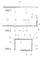
- Fig. 1 is a later peripheral walls of the box body forming plate 1 made of a wood material, plastic, hard foam or other suitable material laminated on at least one side with a plaster base 2.
- the plate 1 is laminated on both sides with a respective plaster carrier 2, 3.
- These plaster base 2, 3 are preferably made of a heavy duty polyurethane-based insulation board with abrasion resistant surface.
- the provided with the plaster carriers 2, 3 plate 1 is then milled from the plaster base 2 on the outside of the box body to be produced opposite side with V-shaped grooves 4, which have an opening angle of 90 ° and reach to the plaster base 2.
- the plate 1 is subdivided into the individual, juxtaposed circumferential walls 5, which are hinged together along their push through the plaster base 2 as a film hinge 6 and therefore can be pivoted against each other by 90 °, as the Fig. 2 can be seen.
- a box body 7 according to the Fig. 3 is only on the walls of the V-shaped grooves 4 to apply an adhesive before the individual peripheral walls 5 are pivoted against each other to miter stop and held in this pivotal position on the adhesive joint in the region of the respective Gehrungshuntes 8.
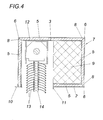
- FIG. 4 and 5 different boxes for receiving a shading in the form of a Venetian blind and a roller shutter are shown.
- the box body 7 of the boxes after the Fig. 4 and 5 have different cross-sectional dimensions and are conventionally provided with an inserted, prefabricated thermal insulation 9, which in turn can be adapted to the male shading.
- the box body 7 are provided with a cleaning strip 10 on the front outer peripheral wall 5 and an edge protection 11 in the region of the passage opening for the respective shading.
- the box body 7 can also be provided with conventional closable by a cover inspection openings, which is not shown for clarity reasons.
- the box for holding a Venetian blind carries in the region of the upper peripheral wall 5, a head rail 12 for receiving the winding device for the lamellae 13 of the Raffstores holding ladder cords.
- the guide for these slats is indicated by the reference numeral 14.
- the box after the Fig. 5 takes the winding shaft 15 for a shutter 16, the slats 17 slide in lateral guide rails 18.
- a fly screen 19 is provided, the winding shaft is denoted by 20.
- the holder of this winding shaft 20 is fixed to the upper peripheral wall 5 of the box body 7.
Landscapes
- Engineering & Computer Science (AREA)
- Structural Engineering (AREA)
- Architecture (AREA)
- Civil Engineering (AREA)
- Blinds (AREA)
Applications Claiming Priority (1)
| Application Number | Priority Date | Filing Date | Title |
|---|---|---|---|
| AT18452009 | 2009-11-20 |
Publications (1)
| Publication Number | Publication Date |
|---|---|
| EP2325433A2 true EP2325433A2 (fr) | 2011-05-25 |
Family
ID=43857622
Family Applications (1)
| Application Number | Title | Priority Date | Filing Date |
|---|---|---|---|
| EP20100450180 Withdrawn EP2325433A2 (fr) | 2009-11-20 | 2010-11-19 | Caisse de réception d'un obscurcissement pour une fenêtre ou une porte ainsi que procédé de fabrication d'une telle caisse |
Country Status (1)
| Country | Link |
|---|---|
| EP (1) | EP2325433A2 (fr) |
Citations (2)
| Publication number | Priority date | Publication date | Assignee | Title |
|---|---|---|---|---|
| DE3628238A1 (de) | 1986-08-20 | 1988-03-10 | Bohn Edith | Rolladenkasten |
| DE102004020418A1 (de) | 2004-03-30 | 2005-10-20 | Sieghard Beeg | Schutzvorrichtung für Fenster und Türen |
-
2010
- 2010-11-19 EP EP20100450180 patent/EP2325433A2/fr not_active Withdrawn
Patent Citations (2)
| Publication number | Priority date | Publication date | Assignee | Title |
|---|---|---|---|---|
| DE3628238A1 (de) | 1986-08-20 | 1988-03-10 | Bohn Edith | Rolladenkasten |
| DE102004020418A1 (de) | 2004-03-30 | 2005-10-20 | Sieghard Beeg | Schutzvorrichtung für Fenster und Türen |
Similar Documents
| Publication | Publication Date | Title |
|---|---|---|
| DE8521854U1 (de) | Rolltor | |
| DE102017118005A1 (de) | Trockenbau-Trennwandsystem sowie Verfahren zur Montage eines derartigen Trockenbau-Trennwandsystems | |
| EP1146193B1 (fr) | Procédé pour la fabrication de profilés de fenêtre | |
| AT511098B1 (de) | Bausatz zur herstellung einer fensterbank | |
| DE202009006044U1 (de) | Stockrahmen und/oder Flügelrahmen | |
| DE102006059854A1 (de) | Armiertes Kunststoffprofil für Fenster-, Türen- und Fassadenelemente | |
| DE202013011085U1 (de) | Anputzleiste, Leiste und Abschlussschiene | |
| EP2022924B1 (fr) | Chambranle pour une fenêtre ou une porte en verre, dormant et système de fenêtre | |
| EP2476854B1 (fr) | Habillage extérieur pour une fenêtre, une porte ou analogue | |
| EP2327855A2 (fr) | Unité de verre isolant et construction de support dotée d'au moins une telle unité de verre isolant | |
| AT501199B1 (de) | Zweiteiliges laibungsanschlussprofil für an putz angrenzende bauteile | |
| DE102014001636B4 (de) | Wandaufbau in Verbindung mit einem Tür- oder Fensterrahmen und eine energieeffiziente Einbauanordnung mit einem Kastenelement | |
| DE102016111266B4 (de) | Zargenprofil und daraus gebildete Montagezarge | |
| AT17423U1 (de) | Führungsschiene einer Gebäudeöffnungsverschattungsvorrichtung | |
| EP2325433A2 (fr) | Caisse de réception d'un obscurcissement pour une fenêtre ou une porte ainsi que procédé de fabrication d'une telle caisse | |
| DE202008011279U1 (de) | Wärmeisolierte Gebäudewand mit einer Türe und/oder einem Fenster | |
| EP2762668A2 (fr) | Profil de raccordement | |
| EP2518253A1 (fr) | Liaison d'angle pour un profilé de recouvrement de chambranle | |
| DE20102772U1 (de) | Holzrahmen für Fensterbaueinheiten | |
| EP2159363B1 (fr) | Paroi d'immeuble isolée thermiquement dotée d'une porte et/ou d'une fenêtre | |
| EP3078798B1 (fr) | Élément de profilé | |
| EP3207958B1 (fr) | Guidage latéral pour une fermeture coupe-feu et fermeture coupe-feu équipée de guidage latéraux | |
| DE202012004616U1 (de) | Fenster, Tür oder dergleichen mit mindestens einem Kantel | |
| DE29607921U1 (de) | Aufrollbares Wandelement aus Glasleisten | |
| DE102009040532A1 (de) | Wärmebrückenfreies Leibungselement |
Legal Events
| Date | Code | Title | Description |
|---|---|---|---|
| PUAI | Public reference made under article 153(3) epc to a published international application that has entered the european phase |
Free format text: ORIGINAL CODE: 0009012 |
|
| AK | Designated contracting states |
Kind code of ref document: A2 Designated state(s): AL AT BE BG CH CY CZ DE DK EE ES FI FR GB GR HR HU IE IS IT LI LT LU LV MC MK MT NL NO PL PT RO RS SE SI SK SM TR |
|
| AX | Request for extension of the european patent |
Extension state: BA ME |
|
| STAA | Information on the status of an ep patent application or granted ep patent |
Free format text: STATUS: THE APPLICATION IS DEEMED TO BE WITHDRAWN |
|
| 18D | Application deemed to be withdrawn |
Effective date: 20140603 |