EP2327518A2 - Adaptateur pour machine-outil - Google Patents
Adaptateur pour machine-outil Download PDFInfo
- Publication number
- EP2327518A2 EP2327518A2 EP10191403A EP10191403A EP2327518A2 EP 2327518 A2 EP2327518 A2 EP 2327518A2 EP 10191403 A EP10191403 A EP 10191403A EP 10191403 A EP10191403 A EP 10191403A EP 2327518 A2 EP2327518 A2 EP 2327518A2
- Authority
- EP
- European Patent Office
- Prior art keywords
- clamping ring
- sleeve
- attachment
- machine tool
- closed position
- Prior art date
- Legal status (The legal status is an assumption and is not a legal conclusion. Google has not performed a legal analysis and makes no representation as to the accuracy of the status listed.)
- Withdrawn
Links
- 238000005096 rolling process Methods 0.000 claims description 21
- 230000006835 compression Effects 0.000 claims description 8
- 238000007906 compression Methods 0.000 claims description 8
- 230000000694 effects Effects 0.000 claims description 2
- 210000002105 tongue Anatomy 0.000 description 11
- 238000006073 displacement reaction Methods 0.000 description 2
- 241000209035 Ilex Species 0.000 description 1
- 230000005540 biological transmission Effects 0.000 description 1
- 230000010354 integration Effects 0.000 description 1
- 238000002955 isolation Methods 0.000 description 1
- 230000000149 penetrating effect Effects 0.000 description 1
- 238000004904 shortening Methods 0.000 description 1
Images


Classifications
-
- B—PERFORMING OPERATIONS; TRANSPORTING
- B25—HAND TOOLS; PORTABLE POWER-DRIVEN TOOLS; MANIPULATORS
- B25F—COMBINATION OR MULTI-PURPOSE TOOLS NOT OTHERWISE PROVIDED FOR; DETAILS OR COMPONENTS OF PORTABLE POWER-DRIVEN TOOLS NOT PARTICULARLY RELATED TO THE OPERATIONS PERFORMED AND NOT OTHERWISE PROVIDED FOR
- B25F3/00—Associations of tools for different working operations with one portable power-drive means; Adapters therefor
-
- B—PERFORMING OPERATIONS; TRANSPORTING
- B23—MACHINE TOOLS; METAL-WORKING NOT OTHERWISE PROVIDED FOR
- B23B—TURNING; BORING
- B23B31/00—Chucks; Expansion mandrels; Adaptations thereof for remote control
- B23B31/02—Chucks
- B23B31/026—Chucks the radial or angular position of the tool being adjustable
- B23B31/0261—Chucks the radial or angular position of the tool being adjustable for centering the tool
-
- B—PERFORMING OPERATIONS; TRANSPORTING
- B23—MACHINE TOOLS; METAL-WORKING NOT OTHERWISE PROVIDED FOR
- B23B—TURNING; BORING
- B23B31/00—Chucks; Expansion mandrels; Adaptations thereof for remote control
- B23B31/02—Chucks
- B23B31/10—Chucks characterised by the retaining or gripping devices or their immediate operating means
- B23B31/107—Retention by laterally-acting detents, e.g. pins, screws, wedges; Retention by loose elements, e.g. balls
-
- B—PERFORMING OPERATIONS; TRANSPORTING
- B23—MACHINE TOOLS; METAL-WORKING NOT OTHERWISE PROVIDED FOR
- B23B—TURNING; BORING
- B23B2231/00—Details of chucks, toolholder shanks or tool shanks
- B23B2231/04—Adapters
-
- Y—GENERAL TAGGING OF NEW TECHNOLOGICAL DEVELOPMENTS; GENERAL TAGGING OF CROSS-SECTIONAL TECHNOLOGIES SPANNING OVER SEVERAL SECTIONS OF THE IPC; TECHNICAL SUBJECTS COVERED BY FORMER USPC CROSS-REFERENCE ART COLLECTIONS [XRACs] AND DIGESTS
- Y10—TECHNICAL SUBJECTS COVERED BY FORMER USPC
- Y10S—TECHNICAL SUBJECTS COVERED BY FORMER USPC CROSS-REFERENCE ART COLLECTIONS [XRACs] AND DIGESTS
- Y10S279/00—Chucks or sockets
- Y10S279/904—Quick change socket
- Y10S279/905—Quick change socket with ball detent
-
- Y—GENERAL TAGGING OF NEW TECHNOLOGICAL DEVELOPMENTS; GENERAL TAGGING OF CROSS-SECTIONAL TECHNOLOGIES SPANNING OVER SEVERAL SECTIONS OF THE IPC; TECHNICAL SUBJECTS COVERED BY FORMER USPC CROSS-REFERENCE ART COLLECTIONS [XRACs] AND DIGESTS
- Y10—TECHNICAL SUBJECTS COVERED BY FORMER USPC
- Y10T—TECHNICAL SUBJECTS COVERED BY FORMER US CLASSIFICATION
- Y10T279/00—Chucks or sockets
- Y10T279/13—Angularly adjustable or indexing
-
- Y—GENERAL TAGGING OF NEW TECHNOLOGICAL DEVELOPMENTS; GENERAL TAGGING OF CROSS-SECTIONAL TECHNOLOGIES SPANNING OVER SEVERAL SECTIONS OF THE IPC; TECHNICAL SUBJECTS COVERED BY FORMER USPC CROSS-REFERENCE ART COLLECTIONS [XRACs] AND DIGESTS
- Y10—TECHNICAL SUBJECTS COVERED BY FORMER USPC
- Y10T—TECHNICAL SUBJECTS COVERED BY FORMER US CLASSIFICATION
- Y10T279/00—Chucks or sockets
- Y10T279/17—Socket type
- Y10T279/17666—Radially reciprocating jaws
- Y10T279/17692—Moving-cam actuator
- Y10T279/17743—Reciprocating cam sleeve
- Y10T279/17752—Ball or roller jaws
-
- Y—GENERAL TAGGING OF NEW TECHNOLOGICAL DEVELOPMENTS; GENERAL TAGGING OF CROSS-SECTIONAL TECHNOLOGIES SPANNING OVER SEVERAL SECTIONS OF THE IPC; TECHNICAL SUBJECTS COVERED BY FORMER USPC CROSS-REFERENCE ART COLLECTIONS [XRACs] AND DIGESTS
- Y10—TECHNICAL SUBJECTS COVERED BY FORMER USPC
- Y10T—TECHNICAL SUBJECTS COVERED BY FORMER US CLASSIFICATION
- Y10T279/00—Chucks or sockets
- Y10T279/17—Socket type
- Y10T279/17761—Side detent
- Y10T279/17786—Spring
-
- Y—GENERAL TAGGING OF NEW TECHNOLOGICAL DEVELOPMENTS; GENERAL TAGGING OF CROSS-SECTIONAL TECHNOLOGIES SPANNING OVER SEVERAL SECTIONS OF THE IPC; TECHNICAL SUBJECTS COVERED BY FORMER USPC CROSS-REFERENCE ART COLLECTIONS [XRACs] AND DIGESTS
- Y10—TECHNICAL SUBJECTS COVERED BY FORMER USPC
- Y10T—TECHNICAL SUBJECTS COVERED BY FORMER US CLASSIFICATION
- Y10T279/00—Chucks or sockets
- Y10T279/32—Means to prevent jaw loosening
-
- Y—GENERAL TAGGING OF NEW TECHNOLOGICAL DEVELOPMENTS; GENERAL TAGGING OF CROSS-SECTIONAL TECHNOLOGIES SPANNING OVER SEVERAL SECTIONS OF THE IPC; TECHNICAL SUBJECTS COVERED BY FORMER USPC CROSS-REFERENCE ART COLLECTIONS [XRACs] AND DIGESTS
- Y10—TECHNICAL SUBJECTS COVERED BY FORMER USPC
- Y10T—TECHNICAL SUBJECTS COVERED BY FORMER US CLASSIFICATION
- Y10T279/00—Chucks or sockets
- Y10T279/34—Accessory or component
- Y10T279/3406—Adapter
Definitions
- the invention relates to a header for a machine tool, preferably a power tool, with a drive shaft which is non-rotatably connected to an output shaft of the machine tool, with a receiving socket on the machine tool or attachment, which is assigned to a respective other part provided sleeve on the receiving socket is pushed, with a clamping ring which cooperates with locking means to effect a locking of the sleeve on the receiving socket in a closed position.
- Such a header for a machine tool is from the WO 2008/068100 A1 known.
- annular spring or a plurality of leaf springs is used to set the attachment on a receiving neck of a machine tool.
- a clamping ring is used, which automatically engages when pushing the attachment on the machine tool, and must be turned to release.
- the disadvantage of the known arrangement consists in a relatively complicated structure.
- the arrangement is not suitable for one-handed operation. In order to achieve a release of the machine tool, the attachment must be taken with one hand, the clamping ring to be rotated and the machine tool to be held with the other hand.
- a tool holder which is releasably connectable to a tool spindle, wherein a guide sleeve is provided with openings for a plurality of radially engageable in the tool spindle engageable locking elements and a manually displaceable locking sleeve which locks the locking elements radially.
- the locking elements are designed as tilting segments, with an axially fixed bearing part and with a radially tiltable into the opening of the guide sleeve penetrating locking part.
- the locking member is used for torque transmission at the same time.
- tool holder is suitable for connecting a drill head with a tool spindle, but not to provide a quick release connection between a header and a machine tool. In particular, this does not allow one-handed operation.
- the invention has for its object to provide a header for a machine tool according to the aforementioned type, with a simple and reliable rotationally fixed connection can be made to the machine tool, with a simple one-hand assembly and disassembly should be possible.
- it should be as clear as possible whether the attachment is correctly mounted.
- the attachment can be locked by movement with one hand on the one hand in its closed position and on the other hand release from the closed position and deduct. Whether the attachment is mounted correctly, can also be easily recognized by the position of the clamping ring. It is thus a significant improvement over the prior art.
- the locking means comprise at least one rolling body, preferably a ball which can be latched into an associated recess in the closed position.
- the clamping ring on a guide surface which cooperates with the at least one rolling body and the recess such that a radial movement of the rolling body for locking in the recess under the action of the bias is effected by an axial movement of the clamping ring and by a Movement of the clamping ring against its bias unlocking from the closed position is effected.
- the locking means comprise centering means for play-free fixing of the attachment to the machine tool in the closed position.
- the centering means may be formed in the form of inclined surfaces on the recess and on the clamping ring, which cooperate with the at least one rolling body.
- the recess is formed as an annular groove on the receiving socket.
- mutually associated engagement means are provided on the machine tool and on the attachment, which allow a determination of the intent in different angular positions on the machine tool.
- the engagement means comprise projections or recesses on a collar of the receiving nozzle and associated recesses or projections on the sleeve.
- the attachment can be set in different angular positions on the machine tool, without the need for special tools are necessary.
- At least one spring element for securing the clamping ring in an open position is provided on the sleeve.
- the spring element releases the clamping ring when sliding the sleeve onto the receiving socket independently.
- the spring element has a first tongue projecting beyond an inner surface of the sleeve.
- an automatic release of the sleeve can be realized by contact of the sleeve with the receiving socket when pushing the sleeve on the receiving socket in a simple manner.
- the spring element is designed as a leaf spring which is pivotally mounted on the sleeve.
- the spring element e.g. as a coil spring
- other embodiments of the spring element e.g. as a coil spring
- an opening is provided on the inner surface of the sleeve through which the tongue of the spring member projects beyond the inner surface of the sleeve.
- the spring element protrudes beyond an outer contour of the sleeve in the open position and secures the clamping ring by abutment against the spring element in the open position.
- the clamping ring is fixed to the sleeve with a compression spring such that it biases the clamping ring upon release of the spring element by sliding the sleeve onto the receiving socket in the direction of the closed position.
- both a release of the spring element when sliding the sleeve on the receiving socket can be achieved as well as a locking of the sleeve with the receiving socket when the closed position is reached.
- a collar is provided on the receiving neck, which cooperates with the push-on sleeve for centering the intent.
- the mutually associated engagement means for centering the intent are formed.
- the object of the invention is further achieved by a machine tool with a front attachment according to one of the preceding claims.
- Fig. 1 is a machine tool 10 in the region of its outer end together with an attached attachment 30 shown enlarged.
- the machine tool 10 may be any machine tool, preferably a hand-held machine tool in the form of a power tool, for example a screwdriver, a drill or the like.
- the header 30 may be any accessory such as an eccentric attachment, angled head or other attachment. All intentions 30 is common, however, that the attachment 30 has a drive shaft 50 which is rotatably coupled to an output shaft 22 of the machine tool 10, which is preferably a positive connection. For reasons of clarity, only the parts which are necessary for connection to the machine tool 10 have been shown by the attachment 30 except for the drive shaft 50 in the figures. Not shown are other functional parts of the attachment, which are basically known and do not belong to the invention, such as e.g. a bevel gear or the like.
- the shape of the machine tool 10 in the region of the output shaft 22 is off Fig. 2 closer.
- the machine tool 10 has a cylindrical output shaft 22 with a positive locking element 24 in the form of a hexagonal recess.
- a basically cylindrical receiving connection 12 is provided, which is widened by a collar 14 on the machine tool side.
- engagement elements 18 are also provided in the form of semi-cylindrical webs, which are arranged at equal angular intervals to each other. In the present case, three webs are arranged at angular intervals of 120 ° to each other on the collar 14.
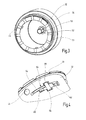
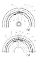
- These webs are corresponding engagement means 51 assigned in the form of correspondingly shaped depressions on the attachment 30, whereby the attachment 30 in its angular position relative to the machine tool 10 is fixed (see. Fig. 3 ). Since the attachment 30 a total of twelve such engagement means 51 are provided in the form of depressions at equal angular intervals to each other, the attachment 30 can be mounted in any angular positions relative to the machine tool 10, wherein the relative position at intervals of 30 ° is variable.
- a recess 16 is also provided in the form of a circumferential annular groove, which is designed to receive a locking means, in the present case in the form of a rolling body, namely a ball.
- the attachment 30 has a cup-shaped sleeve 32 which is pushed onto the receiving socket 12 and with the aid of a spring-loaded clamping ring 34 and generally designated 16, 44 locking means in a closed position on the machine tool 10 can be securely fixed.
- the aforementioned recesses 51 which are associated with the webs 18 on the collar 14 of the receiving nozzle 12, are formed at the front end of the sleeve 32, which is also extended slightly radially outwardly by a collar.
- the recesses 51 of the sleeve 32 are thus in the closed position according to Fig. 1 at the three associated webs 18 on the collar 14, so that at the same time also the centering can be guaranteed hereby, as far as this is not already done via the abutment of the end face of the sleeve 32 on the collar 14.
- a compression spring in the form of a coil spring 36 in the direction of the machine tool 10.
- the compression spring 36 is received in a recess of the clamping ring 34 and limited to the outside (ie the machine tool 10 side facing away) by a disc 38 which is fixed by means of a locking ring 40 on the sleeve 32.
- the compression spring 36 abuts against an inner collar 42 of the clamping ring 34, so that a bias toward the inside, ie in the direction of the machine tool 10 results.
- a movement of the clamping ring 34 in the direction of the machine tool 10 is limited by the rolling body 44 in the form of a ball which is held radially movable in a recess 45 in the wall surface of the sleeve 32 by a guide surface 46 on the clamping ring 34. Falling out of the roller 46 to the inside is prevented by a slightly reduced diameter of the recess 45. Falling out of the roller 46 to the outside is prevented by the overarching clamping ring 34 and the system of the associated guide surface 46.
- a spring element 54 is provided in a correspondingly shaped recess or depression 56 of the sleeve 32 between the clamping ring 34 and the sleeve 32. The spring element 54, whose shape Fig.
- a leaf spring is formed as a leaf spring, with a central portion 58, from which a first leg 60 projects toward one side and a second leg 62 to the opposite side. Parallel to the first and second legs 60, 62 engages the middle part 58, a third leg 64, which serves to fix the spring element 54 in the associated recess 56 of the sleeve 32.
- the spring element 54 can pivot about its middle part 58 with the first leg 60 and the second leg 62, so that a respective associated tongue at the outer end, namely a first tongue 70 on the first leg 60 and a second tongue 72 on the second leg 62, in each case protrudes outwards or inwards beyond the contour of the sleeve 32 ( Fig. 6 . 7 ).
- the second tongue 72 of the spring element 54 is automatically pushed through the opening 74 to the outside, so that the first tongue 70, the collar 42 of the clamping ring 34 releases, so that the clamping ring 34 under the action of the compression spring 36 can move further in the direction of the collar 14 on the receiving socket 12.
- the rolling body 44 is acted upon by the correspondingly shaped guide surface 46 on the inner surface of the clamping ring 34 radially inwardly.
- the guide surface 46 has a first portion in the form of a first inclined surface 47 with a low inclination (below 10 °) relative to the axial direction, followed by a second inclined surface 48 with a greater inclination (about 30 ° -40 °) and finally a third section in the form of a hollow cylindrical surface 49 connects.
- the rolling body 44 is radially acted upon by the first inclined surface 47 of the clamping ring 34 in the direction of the opening 45. Upon reaching the end position then enters the rolling body 44 in the in Fig. 1 shown position, so that the rolling body 44 engages the annular recess of the receiving nozzle 12.
- the attachment 30 is to be released again from the machine tool 10, then only the clamping ring 34 has to be pulled outward against the action of the compression spring 36. Characterized the rolling body 44 is released so that it passes out of the annular groove 16 in the region of the second inclined surface 48 of the clamping ring 34 and between the second inclined surface 48, the cylindrical surface 49 and the outer surface of the receiving nozzle 12 is held. In this case, the spring element 54 returns to its relaxed position in which the clamping ring 34 is locked by the tongue 70 of the spring element 54 (see. Fig. 6 . 7 ).
- the attachment 30 results in a particularly simple attachment of the attachment 30 on the machine tool 10.
- the intent 30 must be recognized only with its positive locking counter 52 on the form-locking element 24 of the output shaft 22 and then pushed with its sleeve 32 on the receiving socket 12, until the clamping ring 34 is released and after being pushed to the end position in which the recesses 51 come to rest on the webs 18, is automatically locked by engagement of the rolling body 44 in the annular groove 16.
Landscapes
- Engineering & Computer Science (AREA)
- Mechanical Engineering (AREA)
- Gripping On Spindles (AREA)
- Jigs For Machine Tools (AREA)
- Details Of Connecting Devices For Male And Female Coupling (AREA)
- Snaps, Bayonet Connections, Set Pins, And Snap Rings (AREA)
- Quick-Acting Or Multi-Walled Pipe Joints (AREA)
Applications Claiming Priority (1)
| Application Number | Priority Date | Filing Date | Title |
|---|---|---|---|
| DE102009057200A DE102009057200A1 (de) | 2009-11-26 | 2009-11-26 | Vorsatz für eine Werkzeugmaschine |
Publications (2)
| Publication Number | Publication Date |
|---|---|
| EP2327518A2 true EP2327518A2 (fr) | 2011-06-01 |
| EP2327518A3 EP2327518A3 (fr) | 2013-07-10 |
Family
ID=43618035
Family Applications (1)
| Application Number | Title | Priority Date | Filing Date |
|---|---|---|---|
| EP10191403.4A Withdrawn EP2327518A3 (fr) | 2009-11-26 | 2010-11-16 | Adaptateur pour machine-outil |
Country Status (4)
| Country | Link |
|---|---|
| US (1) | US8844939B2 (fr) |
| EP (1) | EP2327518A3 (fr) |
| CN (1) | CN102078978B (fr) |
| DE (1) | DE102009057200A1 (fr) |
Cited By (1)
| Publication number | Priority date | Publication date | Assignee | Title |
|---|---|---|---|---|
| EP2942159A1 (fr) * | 2013-12-19 | 2015-11-11 | Metabowerke GmbH | Adaptateur de vis d'angle |
Families Citing this family (18)
| Publication number | Priority date | Publication date | Assignee | Title |
|---|---|---|---|---|
| US9186770B2 (en) | 2010-04-29 | 2015-11-17 | Black & Decker Inc. | Oscillating tool attachment feature |
| US9073195B2 (en) | 2010-04-29 | 2015-07-07 | Black & Decker Inc. | Universal accessory for oscillating power tool |
| US8925931B2 (en) | 2010-04-29 | 2015-01-06 | Black & Decker Inc. | Oscillating tool |
| DE102010030433A1 (de) * | 2010-06-23 | 2011-12-29 | Robert Bosch Gmbh | Handwerkzeugmaschine mit einem Schlagwerk |
| USD832666S1 (en) | 2012-07-16 | 2018-11-06 | Black & Decker Inc. | Oscillating saw blade |
| DE202013100891U1 (de) * | 2013-03-01 | 2014-06-03 | C. & E. Fein Gmbh | Schnittstellenvorsatz für eine Hand-Werkzeugmaschine |
| TWI457214B (zh) * | 2013-07-22 | 2014-10-21 | Loh Torng Hardware Machine Co Ltd | 可選擇性安裝工具件之限位套筒結構 |
| US9579784B2 (en) * | 2013-12-19 | 2017-02-28 | Metabowerke Gmbh | Connecting structure-contained connection device of electric tool for connection with angle adjuster |
| US9751176B2 (en) | 2014-05-30 | 2017-09-05 | Black & Decker Inc. | Power tool accessory attachment system |
| DE102014116032B4 (de) * | 2014-11-04 | 2022-05-25 | C. & E. Fein Gmbh | Schlagschrauber |
| DE102015106162A1 (de) * | 2015-04-22 | 2016-10-27 | Röhm Gmbh | Präzisionsspannsystem |
| USD814900S1 (en) | 2017-01-16 | 2018-04-10 | Black & Decker Inc. | Blade for oscillating power tools |
| US10265778B2 (en) | 2017-01-16 | 2019-04-23 | Black & Decker Inc. | Accessories for oscillating power tools |
| US11034002B2 (en) | 2018-03-23 | 2021-06-15 | Milwaukee Electric Tool Corporation | Attachment mechanism for a power tool |
| WO2020150622A1 (fr) * | 2019-01-17 | 2020-07-23 | Carlson Donald W | Système de marteau de sécurité motorisé à plusieurs courses |
| US12594657B2 (en) | 2023-11-30 | 2026-04-07 | Stanley Black & Decker, Inc. | Multi-headed power tool and systems for fastening heads thereon |
| US12589477B2 (en) | 2023-11-30 | 2026-03-31 | Stanley Black & Decker Inc. | Multi-headed power tool and fastening system for same and systems for fastening heads thereon |
| CN223251576U (zh) * | 2024-09-24 | 2025-08-22 | 永康市一顺工具有限公司 | 一种电动工具的工具头锁扣结构 |
Citations (2)
| Publication number | Priority date | Publication date | Assignee | Title |
|---|---|---|---|---|
| EP1790424A1 (fr) | 2005-11-25 | 2007-05-30 | HILTI Aktiengesellschaft | Porte-outil |
| WO2008068100A1 (fr) | 2006-12-08 | 2008-06-12 | Robert Bosch Gmbh | Élément rapporté pour une machine-outil à main |
Family Cites Families (16)
| Publication number | Priority date | Publication date | Assignee | Title |
|---|---|---|---|---|
| US1052077A (en) * | 1912-01-19 | 1913-02-04 | Eugene C Mcmillan | Handle-fastener. |
| US3090633A (en) * | 1962-04-26 | 1963-05-21 | Max M Seft | Index mechanism for chucks |
| US4231581A (en) * | 1978-10-10 | 1980-11-04 | Ajax Tool Works, Inc. | Pneumatic hammer with twist retainer |
| US4710079A (en) * | 1985-06-11 | 1987-12-01 | T. M. Smith Tool International Corp. | Quick change spindle adapter for tool holder |
| DE4205259C2 (de) * | 1992-02-21 | 1993-12-02 | Atlas Copco Elektrowerkzeuge | Einrichtung zum Werkzeugwechsel an einer handgeführten Werkzeugmaschine |
| JP3423497B2 (ja) * | 1995-09-06 | 2003-07-07 | 株式会社マキタ | 携帯工具のビット装着装置 |
| US6688611B2 (en) * | 1997-12-12 | 2004-02-10 | Black & Decker Inc. | Removable chuck |
| US5951026A (en) * | 1997-12-12 | 1999-09-14 | Black & Decker Inc. | Removable chuck |
| GB9910599D0 (en) * | 1999-05-08 | 1999-07-07 | Black & Decker Inc | Rotary hammer |
| DE10005910B4 (de) * | 2000-02-10 | 2005-10-13 | Robert Bosch Gmbh | Handwerkzeugmaschine mit einem auswechselbaren Werkzeughalter |
| DE10026021A1 (de) * | 2000-05-25 | 2001-11-29 | Hilti Ag | Werkzeugaufnahme für einen Bohrmeissel |
| JP2003071618A (ja) * | 2001-08-30 | 2003-03-12 | Yukiwa Seiko Inc | チャック装置 |
| DE10243290B4 (de) * | 2002-09-18 | 2007-04-05 | Robert Bosch Gmbh | Werkzeugaufnahme |
| JP4616576B2 (ja) * | 2004-04-20 | 2011-01-19 | ユキワ精工株式会社 | チャック装置 |
| DE102004042465A1 (de) * | 2004-09-02 | 2006-03-09 | Robert Bosch Gmbh | Handwerkzeugmaschine mit einer austauschbaren Werkzeugaufnahme |
| EP1946894B1 (fr) * | 2007-01-18 | 2010-05-26 | Metabowerke GmbH | Mandrin à changement rapide d'outil pour marteaux perforateurs ou perceuses à percussion |
-
2009
- 2009-11-26 DE DE102009057200A patent/DE102009057200A1/de not_active Withdrawn
-
2010
- 2010-11-16 EP EP10191403.4A patent/EP2327518A3/fr not_active Withdrawn
- 2010-11-26 CN CN201010566460.2A patent/CN102078978B/zh not_active Expired - Fee Related
- 2010-11-26 US US12/954,733 patent/US8844939B2/en not_active Expired - Fee Related
Patent Citations (2)
| Publication number | Priority date | Publication date | Assignee | Title |
|---|---|---|---|---|
| EP1790424A1 (fr) | 2005-11-25 | 2007-05-30 | HILTI Aktiengesellschaft | Porte-outil |
| WO2008068100A1 (fr) | 2006-12-08 | 2008-06-12 | Robert Bosch Gmbh | Élément rapporté pour une machine-outil à main |
Cited By (1)
| Publication number | Priority date | Publication date | Assignee | Title |
|---|---|---|---|---|
| EP2942159A1 (fr) * | 2013-12-19 | 2015-11-11 | Metabowerke GmbH | Adaptateur de vis d'angle |
Also Published As
| Publication number | Publication date |
|---|---|
| US8844939B2 (en) | 2014-09-30 |
| US20110127731A1 (en) | 2011-06-02 |
| EP2327518A3 (fr) | 2013-07-10 |
| CN102078978A (zh) | 2011-06-01 |
| CN102078978B (zh) | 2016-01-27 |
| DE102009057200A1 (de) | 2011-06-01 |
Similar Documents
| Publication | Publication Date | Title |
|---|---|---|
| DE102009057200A1 (de) | Vorsatz für eine Werkzeugmaschine | |
| EP2792439B1 (fr) | Système de changement rapide pour un porte-outil | |
| EP2146813B1 (fr) | Adaptateur pour faire fonctionner une scie cloche sur une machine d'entraînement | |
| DE102004020982A1 (de) | Kraftgetriebenes Handwerkzeug mit Spanneinrichtung für ein Werkzeug | |
| EP2163358A1 (fr) | Poignée supplémentaire pour une machine-outil manuelle | |
| EP0302992A1 (fr) | Mandrin à reserrage | |
| DE102007035045A1 (de) | Kraftgetriebenes Handwerkzeug | |
| DE3031216C2 (de) | Spannfutter für Gewindebohrer | |
| CH690119A5 (de) | Handbohrmaschine und deren Werkzeughalter. | |
| EP1709931B1 (fr) | Organe moteur, en particulier pièce à main dentaire avec un accouplement détachable pour un porte-outil | |
| DE1919439C3 (de) | Schnellspannfutter für einen Schaft aufweisende Werkzeuge | |
| EP1993787B1 (fr) | Porte-outil à serrage rapide destiné à des inserts de tournevis | |
| DE102011116572B4 (de) | Spannvorrichtung und Werkzeughalter mit einer derartigen Spannvorrichtung | |
| EP3307958A1 (fr) | Dispositif de changement rapide | |
| DE1491029A1 (de) | Zahnaertzliches Handstueck | |
| DE2909469C2 (de) | Spannvorrichtung für chirurgische Werkzeuge | |
| EP1462253B1 (fr) | Dispositif d'embrayage ou de palier pour un cylindre remplacable d'une machine à lacquer ou à imprimer | |
| WO2010112250A1 (fr) | Porte-outil d'une machine-outil manuelle, ainsi que machine-outil manuelle | |
| EP1431003A1 (fr) | Mandrin de serrage actionné mécaniquement et clef pour le dégagement des mors | |
| DE102015112049B3 (de) | Spannzangensystem mit Positionierung | |
| EP3826811B1 (fr) | Logement d'outil et machine-outil manuelle | |
| EP2599927B1 (fr) | Connecteur à fiches pour tuyaux, notamment pour un support publicitaire vertical ou analogue, et tige tubulaire dotée d'un tel connecteur à fiches | |
| AT508218B1 (de) | Handwerkzeughalter | |
| DE102014114101A1 (de) | Anbaueinheit für ein landwirtschaftliches Arbeitsgerät und landwirtschaftliches Arbeitsgerät mit einer solchen Anbaueinheit | |
| EP3795281A1 (fr) | Machine d'usinage |
Legal Events
| Date | Code | Title | Description |
|---|---|---|---|
| PUAI | Public reference made under article 153(3) epc to a published international application that has entered the european phase |
Free format text: ORIGINAL CODE: 0009012 |
|
| AK | Designated contracting states |
Kind code of ref document: A2 Designated state(s): AL AT BE BG CH CY CZ DE DK EE ES FI FR GB GR HR HU IE IS IT LI LT LU LV MC MK MT NL NO PL PT RO RS SE SI SK SM TR |
|
| AX | Request for extension of the european patent |
Extension state: BA ME |
|
| PUAL | Search report despatched |
Free format text: ORIGINAL CODE: 0009013 |
|
| AK | Designated contracting states |
Kind code of ref document: A3 Designated state(s): AL AT BE BG CH CY CZ DE DK EE ES FI FR GB GR HR HU IE IS IT LI LT LU LV MC MK MT NL NO PL PT RO RS SE SI SK SM TR |
|
| AX | Request for extension of the european patent |
Extension state: BA ME |
|
| RIC1 | Information provided on ipc code assigned before grant |
Ipc: B23Q 3/12 20060101ALI20130605BHEP Ipc: B25F 3/00 20060101AFI20130605BHEP |
|
| 17P | Request for examination filed |
Effective date: 20140108 |
|
| RBV | Designated contracting states (corrected) |
Designated state(s): AL AT BE BG CH CY CZ DE DK EE ES FI FR GB GR HR HU IE IS IT LI LT LU LV MC MK MT NL NO PL PT RO RS SE SI SK SM TR |
|
| GRAP | Despatch of communication of intention to grant a patent |
Free format text: ORIGINAL CODE: EPIDOSNIGR1 |
|
| RIC1 | Information provided on ipc code assigned before grant |
Ipc: B23B 31/02 20060101AFI20170420BHEP |
|
| INTG | Intention to grant announced |
Effective date: 20170512 |
|
| STAA | Information on the status of an ep patent application or granted ep patent |
Free format text: STATUS: THE APPLICATION IS DEEMED TO BE WITHDRAWN |
|
| 18D | Application deemed to be withdrawn |
Effective date: 20170923 |