EP2328697B2 - Procédé pour faire fonctionner un dispositif de dressage-étirage à régulation d'allongement superposée à la régulation de traction - Google Patents
Procédé pour faire fonctionner un dispositif de dressage-étirage à régulation d'allongement superposée à la régulation de traction Download PDFInfo
- Publication number
- EP2328697B2 EP2328697B2 EP09779474.7A EP09779474A EP2328697B2 EP 2328697 B2 EP2328697 B2 EP 2328697B2 EP 09779474 A EP09779474 A EP 09779474A EP 2328697 B2 EP2328697 B2 EP 2328697B2
- Authority
- EP
- European Patent Office
- Prior art keywords
- output
- value
- input
- controller
- elongation
- Prior art date
- Legal status (The legal status is an assumption and is not a legal conclusion. Google has not performed a legal analysis and makes no representation as to the accuracy of the status listed.)
- Active
Links
Images

Classifications
-
- B—PERFORMING OPERATIONS; TRANSPORTING
- B21—MECHANICAL METAL-WORKING WITHOUT ESSENTIALLY REMOVING MATERIAL; PUNCHING METAL
- B21D—WORKING OR PROCESSING OF SHEET METAL OR METAL TUBES, RODS OR PROFILES WITHOUT ESSENTIALLY REMOVING MATERIAL; PUNCHING METAL
- B21D1/00—Straightening, restoring form or removing local distortions of sheet metal or specific articles made therefrom; Stretching sheet metal combined with rolling
- B21D1/05—Stretching combined with rolling
Definitions
- the present invention further relates to a computer program for a control device of a drafting jig, the computer program comprising machine commands that are directly executable by the control device, wherein the execution of the machine commands by the control device causes the control device to operate the drafting jig according to such an operating method.
- the present invention further relates to a control device for a stretcher, wherein the control device is designed such that it has at least one operating mode in which it operates the stretcher according to such an operating method.
- Such an operating method and the associated stretcher are from the JP 11 347 630 A known.
- a strip tension control in a treatment line for a material strip which has a number of treatment areas.
- separation roller sets are arranged in front of the first treatment area, between the treatment areas and behind the last treatment area.
- the belt trains which are present in the treatment areas are detected and used in conjunction with a respective desired train for regulating the speed difference between the separation roller set upstream of the respective treatment area and the separation roller set arranged downstream of the respective treatment area.
- Stretching funnels of the type described above are generally operated alternatively in Wergmode or Elongationsregelmode.
- Switzerlandregelmode there is no elongation of the band.
- the output speed is equal to the input speed.
- the corresponding speed setpoints also match.
- the tape tension is not regulated in the prior art.
- the strip tension is monitored for compliance with an absolute value. If the absolute strip tension exceeds a maximum permissible strip tension, the elongation setpoint is reduced in order to lower the strip tension again. If the absolute strip tension falls below the maximum permissible strip tension, the elongation setpoint is slowly increased back to the original elongation setpoint via a ramp function.
- Another problem of the prior art is that during common changes of the speed setpoints, ie during acceleration and deceleration of the belt, strong deviations of the actual actual elongation from the elongation setpoint occur.
- the object of the present invention is to provide possibilities by means of which vibrations in the current strip tension and in the elongation setpoint can be intercepted in a simple manner and, if possible, also the deviations in the actual elongation during acceleration and deceleration processes can be reduced.
- the elongation controller and the draft regulator can be designed as required. It is currently preferred that the elongation controller is designed as a PI controller and that the tension controller is designed as a P controller or as a PI controller.
- the output-side speed setpoint is determined by multiplying the input-side speed setpoint by the elongation setpoint.
- the object is further achieved by a computer program having the features of claim 5.
- the execution of the machine commands by the control device causes the control device to operate the stretcher according to an operating method according to the invention.
- the computer program can be stored on a mobile data carrier. Alternatively, it may be stored in the controller.
- control device having the features of claim 8.
- the control device is thus designed such that it has at least one operating mode in which it operates the stretcher according to an operating method according to the invention.
- the object is achieved by a stretcher with the features of claim 12.
- the stretcher has a control device designed according to the invention.
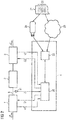
- a stretch leveler comprises an input-side conveyor element 1, a bending element 2, and an output-side conveyor element 3.
- the input-side conveyor element 1 and the output-side conveyor element 3, optionally also the bending element 2, are controlled by a control device 4.
- the input-side conveyor element 1 is usually designed as an S-roller set. It may have two or more than two rollers 5a to 5d. Is shown in FIG. 1 an embodiment of the input-side conveyor element 1 with four rollers 5a to 5d. This embodiment is common in the context of the present invention, but not mandatory.
- the rollers 5a to 5d of the input-side conveyor element 1 are at least partially driven.
- the roller 5d that is, the bending member 2 immediately upstream roller 5d, is driven.
- the input-side conveyor element 1 leads to the bending element 2 a band 6.
- the band 6 is usually a metal band 6, for example a steel, aluminum or copper band. In some cases, the band 6 may also be formed as a textile band.
- the feeding of the belt 6 to the bending element 2 takes place with an input speed v1.
- an input-side speed controller 7 is provided to which the input speed v1 and an input-side speed setpoint v1 * are supplied.
- the input-side speed controller 7 causes the input-side conveyor element 1 is controlled to the input-side speed setpoint v1 *. It outputs for this purpose a suitable control signal S1 to the input-side conveyor element 1. For example, it can control a drive of the roller 5d accordingly.
- the output-side conveyor element 3 is usually designed as an S-roller set. Analogously to the input-side conveying element 1, the S-roller set may have two or more than two rollers 8a to 8d. Shown in FIG. 1 four rollers 8a to 8d. This embodiment is common in the context of the present invention, but not mandatory.
- rollers 8a to 8d of the output-side conveyor element 3 are at least partially driven.
- the innermost roller 8a that is, the bending element 2 immediately downstream roller 8a, is driven.
- an output-side speed controller 9 is provided to which the output speed v2 and an output-side speed setpoint v2 * are supplied.
- the output-side speed controller 9 causes the output-side conveyor element 3 to be regulated to the output-side speed setpoint value v2 *. It outputs for this purpose a suitable actuating signal S2 to the output-side conveyor element 3. For example, it can drive a drive of the roller 8a accordingly.
- the bending element 2 has a number of rollers 10. Shown in FIG. 1 however, the number of rollers 10 of the flexure 2 could alternatively be greater or less than five.
- the rollers 10 are not driven in the rule. They could, however, be powered.
- the rollers 10 of the bending element 2 are employed on the belt 6. By means of the rollers 10, the band 6 is deflected in the bending element 2 alternately up and down.
- the stretcher is usually operated, inter alia, in a Switzerlandregelmode.
- the output-side speed setpoint v2 * is equal to the input-side speed setpoint v1 *.
- an actual tension value Z is detected, which prevails in the belt 6 between the conveying elements 1, 3.
- the actual train value Z is regulated to a train setpoint Z *.
- the Switzerlandregelmode may also be possible in the context of the present invention. This is not important. It is crucial that the stretcher be operated (at least among others) in a Elongationsregelmode.
- the elongation control mode will be explained in more detail below.
- the output-side speed setpoint v2 * is greater than the input-side speed setpoint v1 *.
- the output speed v2 is also greater than the input speed v1.
- the speed difference between the output speed v2 and the input speed v1 is in this case such that the belt 6 is plastically stretched between the conveyor elements 1, 3.
- the input speed v1 and the output speed v2 are detected.
- the detection takes place by means of corresponding speed detection elements 12, 13.
- the speeds v1, v2 of the outer rollers 5a, 8d are detected.
- the detected velocities v1, v2 are supplied not only to the speed controllers 7, 9, but also to an elongation detector 14 which determines an elongation actual value e for the band 6 on the basis of the input speed v1 and the initial speed v2.
- the elongation actual value e and an elongation setpoint e * (with e *> 1) are fed to an elongation controller 15.
- the elongation controller 15 determines a train setpoint Z * based on the values e, e * supplied to it.
- the elongation controller 15 can be of any desired design, for example as a P controller, as a PI controller, as a PID controller, as a PT1 controller or as a PT2 controller. Usually, the elongation controller 15 is designed as a PI controller.
- the tension controller 16 is further supplied with the Weristwert Z.
- the Weristwert Z can be detected by means of the train detection element 11 or otherwise by means of another, not shown Geber appliedselements.
- the tension controller 16 determines a speed addition setpoint ⁇ v * based on the values Z and Z * or Z and ZMAX * supplied to it.
- the tension regulator 16 can be designed as desired for this purpose.
- the above statements on the design of the elongation controller 15 are analogously applicable.
- the tension controller 16 is designed either as a P controller or as a PI controller. Both embodiments are in FIG. 1 shown. However, since both embodiments are alternative to each other, both embodiments are in FIG. 1 shown only by dashed lines.
- the additional speed setpoint value ⁇ v * is fed to a connection element 18.
- the Aufschaltelement 18 is further supplied to the output side speed setpoint v2 *.
- the connection element 18 switches on the additional speed setpoint value ⁇ v * to the output speed setpoint value v2 *.
- the output speed setpoint v2 * can in principle be determined in any way.
- the output-side speed setpoint v2 * may first be set equal to the input-side speed setpoint v1 * or may differ from the input-side speed setpoint v1 * by a fixed value.
- the input speed setpoint v1 * and the elongation setpoint e * are supplied to a multiplier 19.
- the multiplier 19 determines the output-side speed command value v2 * by multiplying the input-side speed command value v1 * by the elongation command value e *.
- control device 4 as shown in FIG. 1 is built in hardware. Often, however, the control device 4 according to the representation of FIG. 2 designed as a software programmable controller. In this case, the control device 4 has a processor 20, which executes a computer program 21. The computer program 21 in this case determines the mode of action of the control device 4.
- the computer program 21 comprises according to FIG. 2 Machine commands 22, which are directly abaillebar by the control device 4 (more precisely: by the processor 20 of the control device 4).
- the execution of the machine commands 22 by the control device 4 causes the control device 4 to operate the stretcher as described above in connection with FIG FIG. 1 was explained.
- the computer program 21 must be stored in an internal memory 23 of the control device 4. At this time, the computer program 21 is thus stored in the control device 4. However, the feeding of the computer program 21 to the control device 4 can take place in various ways.
- the control device 4 must have a corresponding interface for the mobile data carrier 24.
- the mobile data carrier 24 can be designed as needed. For example, it can be used as a CD-ROM, as an SD memory card or as shown in FIG. 2 be designed as a USB memory stick.
- control device 4 it is possible to supply the computer program 21 of the control device 4 via a computer-computer connection 25.
- the control device 4 must have a corresponding interface to the computer-computer connection 25.
- the computer-computer connection 25 can be, for example, a LAN or a larger computer network, in particular the World Wide Web.
- the present invention has many advantages.
- a stable, vibration-free behavior of the stretch leveler can be achieved.
- the strong deviations between elongation setpoint e * and elongation actual value e which occur in the prior art, can be significantly reduced. In tests, the deviations could be reduced to approx. 20% of the previous deviation.
- the elongation actual value e also follows the elongation setpoint e * quickly and without appreciable overshoot when the elongation setpoint e * changes.
- the stretch leveler runs more stable. As a result, a significant production and quality improvement can be achieved.
Landscapes
- Engineering & Computer Science (AREA)
- Mechanical Engineering (AREA)
- Controlling Rewinding, Feeding, Winding, Or Abnormalities Of Webs (AREA)
- Control Of Metal Rolling (AREA)
Claims (12)
- Procédé pour faire fonctionner un dispositif de dressage-étirage, qui comprend un élément (1) convoyeur du côté de l'entrée, un élément (2) de cintrage et un élément (3) convoyeur du côté de la sortie,- dans lequel on apporte une bande (6), notamment un feuillard (6) métallique, à l'élément (2) de cintrage par l'élément (1) convoyeur du côté de l'entrée à une vitesse (v1) d'entrée,- dans lequel on évacue de l'élément (2) de cintrage la bande (6) par l'élément (3) convoyeur du côté de la sortie à une vitesse (v2) de sortie,- dans lequel la vitesse (v2) de sortie est plus grande que la vitesse (v1) d'entrée, de manière à étirer plastiquement la bande (6),- dans lequel on dévie en alternance vers le haut et vers le bas la bande (6) dans l'élément (2) de cintrage, au moyen de rouleaux (10) de l'élément (2) de cintrage appliqués à la bande (6),- dans lequel on règle l'élément (1) convoyeur du côté de l'entrée à une valeur (v1*) de consigne de vitesse du côté de l'entrée et l'élément (3) convoyeur du côté de la sortie a une valeur (v2*) de consigne de vitesse du côté de la sortie,- dans lequel on détecte la vitesse (v1) d'entrée et la vitesse (v2) de sortie et on en détermine une valeur (e) réelle d'allongement de la bande (6),- dans lequel on envoie la valeur (e) d'allongement et une valeur (e*) de consigne d'allongement à un régleur (15) d'allongement,caractérisé- en ce que le régleur (15) d'allongement détermine une valeur (Z*) de consigne de traction, au moyen des valeurs (e, e*) qui lui sont envoyées,- en ce que l'on limite la valeur (Z*) de consigne de traction à une valeur (ZMAX*) de consigne de traction maximum,- en ce que l'on détecte une valeur (Z) réelle de traction,- en ce que l'on envoie la valeur (Z) réelle de traction et la valeur (Z*) de consigne de traction limitée à la valeur (ZMAX*) de consigne de traction maximum à un régleur (16) de traction, qui détermine une valeur (δv*) de consigne supplémentaire de vitesse au moyen des valeurs (Z, Z*) qui lui sont envoyées, et- en ce que l'on met la valeur (δv*) de consigne supplémentaire de vitesse à la valeur (v2*) de consigne de vitesse du côté de la sortie.
- Procédé suivant la revendication 1,
caractérisé en ce que le régleur (15) d'allongement est constitué en régleur PI. - Procédé suivant la revendication 1 ou 2,
caractérisé en ce que le régleur (6) de traction est constitué en régleur P ou en régleur PI. - Procédé suivant la revendication 1, 2 ou 3,
caractérisé en ce que l'on détermine la valeur (v2*) de consigne de vitesse du côté de la sortie en multipliant la valeur (v1*) de consigne de vitesse du côté de l'entrée par la valeur (e*) de consigne d'allongement. - Programme informatique pour un dispositif (4) de commande d'un dispositif de dressage-étirage, le programme informatique comprenant des instructions (22) machine, qui peuvent être traitées directement par le dispositif (4) de commande, le traitement des instructions (22) machine par le dispositif (4) de commande faisant que le dispositif (4) de commande fait fonctionner le dispositif de dressage-étirage suivant un procédé de fonctionnement suivant l'une des revendications précédentes.
- Programme informatique suivant la revendication 5,
caractérisé en ce qu'il est mémorisé sur un support (24) mobile de données. - Programme informatique suivant la revendication 5,
caractérisé en ce qu'il est mémorisé dans le dispositif (4) de commande. - Dispositif de commande d'un dispositif de dressage-étirage, qui comprend un élément (1) convoyeur du côté de l'entrée, un élément (2) de cintrage et un élément (3) convoyeur du côté de la sortie,- dans lequel le dispositif de commande a un régleur (7) de vitesse du côté de l'entrée, un régleur (9) de vitesse du côté de la sortie, un détecteur (14) d'allongement, un régleur (15) d'allongement, un régleur (16) de traction, un élément (17) de limitation et un élément (18) d'ajustement,- dans lequel le dispositif de commande a au moins un mode de fonctionnement, dans lequel les éléments (7, 9, 14, 15, 16, 17, 18) mentionnés du dispositif de commande coopèrent de la manière suivante :- au régleur (7) de vitesse du côté de l'entrée est envoyée une valeur (v1) de vitesse d'entrée, à laquelle une bande (6), notamment un feuillard (6) métallique, est envoyée à l'élément (2) de cintrage par l'élément (1) convoyeur du côté de l'entrée ;- le régleur (7) de vitesse du côté de l'entrée émet vers l'élément (1) convoyeur du côté de l'entrée un signal (S1) de réglage du côté de l'entrée, au moyen duquel l'élément (1) convoyeur du côté de l'entrée est réglé à une valeur (v1*) de consigne de vitesse du côté de l'entrée ;- au régleur (9) de vitesse du côté de la sortie est envoyée une valeur (v2) de vitesse du côté de la sortie, à laquelle la bande (6) est évacuée de l'élément (2) de cintrage par l'élément (3) convoyeur du côté de la sortie ;- le régleur (9) de vitesse du côté de la sortie émet vers l'élément (3) convoyeur du côté de la sortie un signal (S2) de réglage du côté de la sortie, au moyen duquel l'élément (3) convoyeur du côté de la sortie est réglé à une valeur (v2*+δv*) résultante de consigne de vitesse du côté de la sortie ;- la valeur (v1) de vitesse d'entrée et la valeur (v2) de vitesse de sortie sont envoyées au détecteur (14) d'allongement ;- le détecteur (14) d'allongement détecte une valeur (e) réelle d'allongement de la bande (6) à partir des valeurs (v1, v2) qui lui sont envoyées ;- la valeur (e) réelle d'allongement et une valeur (e*) de consigne d'allongement sont envoyées au régulateur (15) d'allongement ;- le régulateur (15) d'allongement détermine une valeur (Z*) de consigne de traction au moyen des valeurs (e, e*) qui lui sont envoyées ;- l'élément (17) de limitation est monté en aval du régleur (15) d'allongement et limite la valeur (Z*) de consigne de traction à une valeur (ZMAX*) de consigne de traction maximum ;- une valeur (Z) réelle de traction détectée et la valeur (Z*) de consigne de traction limitée à la valeur (ZMAX*) de consigne de traction maximum sont envoyées au régleur (16) de traction ;- le régleur (16) de traction détermine une valeur (δv*) de consigne supplémentaire de vitesse au moyen des valeurs (Z, Z*) qui lui sont envoyées ;- la valeur (δv*) de consigne supplémentaire de vitesse et la valeur (v2*) de consigne provisoire de vitesse du côté de la sortie sont envoyées à l'élément (18) d'ajustement ;- l'élément (18) d'ajustement met la valeur (δv*) de consigne supplémentaire de vitesse à la valeur (v2*) de consigne provisoire de vitesse du côté de la sortie et envoie la valeur (v2*) de consigne provisoire de vitesse du côté de la sortie additionnée de la valeur (δv*) de consigne supplémentaire de vitesse ajustée au régleur (9) de vitesse du côté de la sortie comme valeur (v2*+δv*) résultante de consigne de vitesse du côté de la sortie,
la valeur (v2*+δv*) résultante de consigne de vitesse du côté de la sortie est plus grande que la valeur (v1*) de consigne de vitesse d'entrée, de manière, en mettant l'élément (1) convoyeur du côté de l'entrée à la valeur (v1*) de consigne de vitesse d'entrée et en mettant l'élément (3) convoyeur du côté de la sortie à la valeur (v2*+δv*) résultante de consigne de vitesse du côté de la sortie, à étirer plastiquement la bande (6) entre les éléments (1, 3) convoyeurs. - Dispositif de commande suivant la revendication 8, caractérisé en ce que le régleur (15) d'allongement est constitué en régleur PI.
- Dispositif de commande suivant la revendication 8 ou 9, caractérisé en ce que le régleur (16) de traction est constitué en régleur P ou en régleur PI.
- Dispositif de commande suivant la revendication 8, 9 ou 10, caractérisé en ce que le dispositif de commande a un multiplicateur (19), auquel sont envoyées la valeur (v1*) de consigne de vitesse du côté de l'entrée et la valeur (e*) de consigne d'allongement, et qui détermine dans le au moins un mode de fonctionnement la valeur (v2*) de consigne de vitesse du côté de la sortie en multipliant la valeur (v1*) de consigne de vitesse du côté de l'entrée par la valeur (e*) de consigne d'allongement.
- Dispositif de dressage-étirage d'une bande (6), notamment d'un feuillard (6) métallique,- dans lequel le dispositif de dressage-étirage comprend un élément (1) convoyeur du côté de l'entrée, un élément (2) de cintrage et un élément (3) convoyeur du côté de la sortie,- dans lequel la bande (6) peut être apportée à l'élément (2) de cintrage dans l'élément (1) convoyeur du côté de l'entrée,- dans lequel la bande (6) peut être évacuée de l'élément (2) de cintrage par l'élément (3) convoyeur du côté de la sortie,- dans lequel la bande (6) est déviée en alternance vers le haut et vers le bas dans l'élément (2) de cintrage, au moyen de rouleaux de l'élément (2) de cintrage appliqués o la bande (6),- dans lequel le dispositif de dressage-étirage a un dispositif (4) de commande suivant l'une des revendications 8 à 11.
Priority Applications (1)
| Application Number | Priority Date | Filing Date | Title |
|---|---|---|---|
| PL09779474T PL2328697T3 (pl) | 2008-09-01 | 2009-05-14 | Sposób eksploatacji prostownicy rozciągającej z nadrzędną regulacją wydłużenia i podrzędną regulacją naciągu |
Applications Claiming Priority (2)
| Application Number | Priority Date | Filing Date | Title |
|---|---|---|---|
| DE102008045340A DE102008045340A1 (de) | 2008-09-01 | 2008-09-01 | Betriebsverfahren für einen Streckrichter mit überlagerter Elongationsregelung und unterlagerter Zugregelung |
| PCT/EP2009/055820 WO2010022992A1 (fr) | 2008-09-01 | 2009-05-14 | Procédé pour faire fonctionner un dispositif de dressage-étirage à régulation d'allongement superposée à la régulation de traction |
Publications (3)
| Publication Number | Publication Date |
|---|---|
| EP2328697A1 EP2328697A1 (fr) | 2011-06-08 |
| EP2328697B1 EP2328697B1 (fr) | 2013-01-30 |
| EP2328697B2 true EP2328697B2 (fr) | 2019-10-09 |
Family
ID=41010016
Family Applications (1)
| Application Number | Title | Priority Date | Filing Date |
|---|---|---|---|
| EP09779474.7A Active EP2328697B2 (fr) | 2008-09-01 | 2009-05-14 | Procédé pour faire fonctionner un dispositif de dressage-étirage à régulation d'allongement superposée à la régulation de traction |
Country Status (5)
| Country | Link |
|---|---|
| EP (1) | EP2328697B2 (fr) |
| CN (1) | CN102137725B (fr) |
| DE (1) | DE102008045340A1 (fr) |
| PL (1) | PL2328697T3 (fr) |
| WO (1) | WO2010022992A1 (fr) |
Families Citing this family (3)
| Publication number | Priority date | Publication date | Assignee | Title |
|---|---|---|---|---|
| WO2013035449A1 (fr) * | 2011-09-07 | 2013-03-14 | スチールプランテック株式会社 | Machine à planer et procédé de planage de plaque métallique utilisant ce niveleur |
| WO2014017944A1 (fr) * | 2012-07-27 | 2014-01-30 | Totsky Ivan Timofeevich | Procédé de déformation à froid d'une bande de métal ininterrompue |
| DE102018111627A1 (de) * | 2018-01-23 | 2019-07-25 | Klaus Lenz | Streck-Biege-Richtanlage und Verfahren zu deren Betätigung |
Citations (3)
| Publication number | Priority date | Publication date | Assignee | Title |
|---|---|---|---|---|
| JPS6149730A (ja) † | 1984-08-18 | 1986-03-11 | Yaskawa Electric Mfg Co Ltd | テンシヨンレベラ |
| JPH02179320A (ja) † | 1988-12-28 | 1990-07-12 | Yaskawa Electric Mfg Co Ltd | テンションレベラ制御方法 |
| JP2004255444A (ja) † | 2003-02-27 | 2004-09-16 | Jfe Steel Kk | テンションレベラによる伸び率制御方法 |
Family Cites Families (11)
| Publication number | Priority date | Publication date | Assignee | Title |
|---|---|---|---|---|
| DE1602589A1 (de) * | 1967-05-31 | 1970-03-26 | Ungerer Irma | Anordnung zum Streckrichten kontinuierlich durchlaufender Blechbaender |
| JPS5581009A (en) * | 1978-12-14 | 1980-06-18 | Nippon Steel Corp | Skin-pass rolling shape control method of cold rolled hoop after continuous annealing and equipment thereof |
| DE2911983C2 (de) * | 1979-03-27 | 1986-03-20 | Mannesmann AG, 4000 Düsseldorf | Vorrichtung zum Regeln von Anlagen zum Streckbiegerichten kontinuierlich durchlaufender Bänder |
| DE3525343C1 (de) * | 1985-04-20 | 1986-12-11 | Bwg Bergwerk- Und Walzwerk-Maschinenbau Gmbh, 4100 Duisburg | Verfahren und Vorrichtung zum Kontinuierlichen Richten von Metallbändern |
| GB2174027B (en) * | 1985-04-20 | 1988-07-13 | Bwg Bergwerk Walzwerk | Process and equipment for continuous flattening of particularly thin metal strip |
| JPH0768319A (ja) * | 1993-06-29 | 1995-03-14 | Kawasaki Steel Corp | テンションレベラの制御方法 |
| DE19520541C2 (de) * | 1995-06-03 | 1999-01-14 | Bwg Bergwerk Walzwerk | Verfahren und Vorrichtung zum Korrigieren eines gewalzten, in der Bandebene horizontal gebogenen Metallbandes, insbesondere eines Metallbandes mit einer Banddicke von 0,5 mm bis 2,0 mm |
| JPH11347630A (ja) * | 1998-06-03 | 1999-12-21 | Yodogawa Steel Works Ltd | テンションレベラーでの金属板の伸び率実績値の算出方法と伸び率制御方法 |
| DE10342798B3 (de) | 2003-09-16 | 2005-03-10 | Siemens Ag | Bandzugregelung in einer Behandlungslinie für Materialband, insbesondere Metallband |
| DE102004048658A1 (de) * | 2004-10-06 | 2006-04-20 | Sms Demag Ag | Vorrichtung zum kontinuierlichen Zugrecken eines Metallbandes und Verfahren zum Betreiben einer solchen Vorrichtung |
| CN201464909U (zh) * | 2009-08-11 | 2010-05-12 | 天津赛瑞机器设备有限公司 | 基于plc的芯棒压力矫直机控制系统 |
-
2008
- 2008-09-01 DE DE102008045340A patent/DE102008045340A1/de not_active Withdrawn
-
2009
- 2009-05-14 CN CN2009801338135A patent/CN102137725B/zh active Active
- 2009-05-14 WO PCT/EP2009/055820 patent/WO2010022992A1/fr not_active Ceased
- 2009-05-14 EP EP09779474.7A patent/EP2328697B2/fr active Active
- 2009-05-14 PL PL09779474T patent/PL2328697T3/pl unknown
Patent Citations (3)
| Publication number | Priority date | Publication date | Assignee | Title |
|---|---|---|---|---|
| JPS6149730A (ja) † | 1984-08-18 | 1986-03-11 | Yaskawa Electric Mfg Co Ltd | テンシヨンレベラ |
| JPH02179320A (ja) † | 1988-12-28 | 1990-07-12 | Yaskawa Electric Mfg Co Ltd | テンションレベラ制御方法 |
| JP2004255444A (ja) † | 2003-02-27 | 2004-09-16 | Jfe Steel Kk | テンションレベラによる伸び率制御方法 |
Also Published As
| Publication number | Publication date |
|---|---|
| PL2328697T3 (pl) | 2013-07-31 |
| CN102137725A (zh) | 2011-07-27 |
| CN102137725B (zh) | 2013-09-11 |
| DE102008045340A1 (de) | 2010-03-04 |
| EP2328697A1 (fr) | 2011-06-08 |
| EP2328697B1 (fr) | 2013-01-30 |
| WO2010022992A1 (fr) | 2010-03-04 |
Similar Documents
| Publication | Publication Date | Title |
|---|---|---|
| EP3411162B1 (fr) | Reglage de position de bande | |
| DE60016999T2 (de) | Verfahren und Vorrichtung zum Regeln der Bandform beim Bandwalzen | |
| EP2477764A1 (fr) | Procédé et dispositif pour le dressage par traction et flexion continu de bandes métalliques | |
| EP3208673B1 (fr) | Étalonnage en ligne d'une emprise de laminage d'une cage de laminoir | |
| EP3210681A1 (fr) | Dispositif et procédé de laminage de matériau en bande à épaisseur variable | |
| EP2790846B1 (fr) | Procédé de traitement de produits laminés dans un laminoir | |
| DE102014215397B4 (de) | Bandlageregelung mit optimierter Reglerauslegung | |
| EP2328697B1 (fr) | Procédé pour faire fonctionner un dispositif de dressage-étirage à régulation d'allongement superposée à la régulation de traction | |
| EP3544751B1 (fr) | Réglage de position de bande consistant à positionner des guides latéraux sur la bande métallique, avec limitation de force | |
| EP3231522B1 (fr) | Controle robuste de tension de bande | |
| EP2328696B1 (fr) | Procédé pour commander et/ou régler un mouvement de glissement d'un rouleau relativement à une bande, dispositif de commande et/ou de réglage, code de programme lisible par machine, support d'enregistrement et installation industrielle | |
| EP2340133A2 (fr) | Dispositif de réglage d'une charge d'entraînement pour une pluralité de dispositifs d'entraînement d'un train de laminage destiné au laminage d'un matériau à laminer, dispositif de commande et/ou de réglage, support de stockage, code programme et installation de laminage | |
| EP2135690A1 (fr) | Train de laminage continental doté d'intégrations et/ou de détachements de cages de laminoir en fonctionnement continu | |
| EP2817110A1 (fr) | Machine à dresser en tandem et procédé de dressage comprenant le positionnement de l'article à dresser | |
| EP2283941A1 (fr) | Procédé de commande et/ou de réglage d'un leveur de boucle se trouvant dans une chaîne de laminage, commande et/ou dispositif de réglage pour une chaîne de laminage et chaîne de laminage | |
| EP2460597A1 (fr) | Procédé de commande d'une voie de laminage en tandem, dispositif de commande et/ou de réglage pour une voie de laminage en tandem, code de programme lisible par machine, support de stockage et voie de laminage en tandem | |
| EP2268427B1 (fr) | Procédé d'exploitation pour un train de laminoir à froid avec dynamique améliorée | |
| EP3798750B1 (fr) | Procédé de surveillance et de commande d'une installation de laminage de produits métalliques | |
| DE102014215396A1 (de) | Differenzzugregelung mit optimierter Reglerauslegung | |
| EP2839892A1 (fr) | Procédé de traitement de produits laminés dans une chaîne de laminage et chaîne de laminage | |
| EP3715000B1 (fr) | Procédé permettant d'éviter les ondulations lors du laminage des bandes métalliques | |
| EP4072747A1 (fr) | Cage de laminoir à chaud pour laminoir à chaud et pour fabriquer un produit métallique plat, laminoir à chaud et procédé de fonctionnement d'un laminoir à chaud | |
| EP4299904B1 (fr) | Procédé de régulation de pompes à fluide à vitesse variable | |
| DE102017212106B4 (de) | Walzsteuervorrichtung, walzsteuerverfahren und programm dafür | |
| DE102018200166B4 (de) | Steuervorrichtung, Steuerverfahren und Steuerprogramm eines Walzwerks |
Legal Events
| Date | Code | Title | Description |
|---|---|---|---|
| PUAI | Public reference made under article 153(3) epc to a published international application that has entered the european phase |
Free format text: ORIGINAL CODE: 0009012 |
|
| 17P | Request for examination filed |
Effective date: 20110208 |
|
| AK | Designated contracting states |
Kind code of ref document: A1 Designated state(s): AT BE BG CH CY CZ DE DK EE ES FI FR GB GR HR HU IE IS IT LI LT LU LV MC MK MT NL NO PL PT RO SE SI SK TR |
|
| AX | Request for extension of the european patent |
Extension state: AL BA RS |
|
| 17Q | First examination report despatched |
Effective date: 20110713 |
|
| DAX | Request for extension of the european patent (deleted) | ||
| GRAP | Despatch of communication of intention to grant a patent |
Free format text: ORIGINAL CODE: EPIDOSNIGR1 |
|
| GRAS | Grant fee paid |
Free format text: ORIGINAL CODE: EPIDOSNIGR3 |
|
| GRAA | (expected) grant |
Free format text: ORIGINAL CODE: 0009210 |
|
| AK | Designated contracting states |
Kind code of ref document: B1 Designated state(s): AT BE BG CH CY CZ DE DK EE ES FI FR GB GR HR HU IE IS IT LI LT LU LV MC MK MT NL NO PL PT RO SE SI SK TR |
|
| REG | Reference to a national code |
Ref country code: GB Ref legal event code: FG4D Free format text: NOT ENGLISH |
|
| REG | Reference to a national code |
Ref country code: CH Ref legal event code: EP |
|
| REG | Reference to a national code |
Ref country code: AT Ref legal event code: REF Ref document number: 595619 Country of ref document: AT Kind code of ref document: T Effective date: 20130215 Ref country code: CH Ref legal event code: EP |
|
| REG | Reference to a national code |
Ref country code: IE Ref legal event code: FG4D Free format text: LANGUAGE OF EP DOCUMENT: GERMAN |
|
| RAP2 | Party data changed (patent owner data changed or rights of a patent transferred) |
Owner name: SIEMENS AKTIENGESELLSCHAFT |
|
| REG | Reference to a national code |
Ref country code: DE Ref legal event code: R096 Ref document number: 502009006164 Country of ref document: DE Effective date: 20130321 |
|
| REG | Reference to a national code |
Ref country code: SE Ref legal event code: TRGR |
|
| REG | Reference to a national code |
Ref country code: LT Ref legal event code: MG4D |
|
| REG | Reference to a national code |
Ref country code: NL Ref legal event code: VDEP Effective date: 20130130 |
|
| PG25 | Lapsed in a contracting state [announced via postgrant information from national office to epo] |
Ref country code: BG Free format text: LAPSE BECAUSE OF FAILURE TO SUBMIT A TRANSLATION OF THE DESCRIPTION OR TO PAY THE FEE WITHIN THE PRESCRIBED TIME-LIMIT Effective date: 20130430 Ref country code: ES Free format text: LAPSE BECAUSE OF FAILURE TO SUBMIT A TRANSLATION OF THE DESCRIPTION OR TO PAY THE FEE WITHIN THE PRESCRIBED TIME-LIMIT Effective date: 20130511 Ref country code: NO Free format text: LAPSE BECAUSE OF FAILURE TO SUBMIT A TRANSLATION OF THE DESCRIPTION OR TO PAY THE FEE WITHIN THE PRESCRIBED TIME-LIMIT Effective date: 20130430 Ref country code: LT Free format text: LAPSE BECAUSE OF FAILURE TO SUBMIT A TRANSLATION OF THE DESCRIPTION OR TO PAY THE FEE WITHIN THE PRESCRIBED TIME-LIMIT Effective date: 20130130 Ref country code: IS Free format text: LAPSE BECAUSE OF FAILURE TO SUBMIT A TRANSLATION OF THE DESCRIPTION OR TO PAY THE FEE WITHIN THE PRESCRIBED TIME-LIMIT Effective date: 20130530 |
|
| PGFP | Annual fee paid to national office [announced via postgrant information from national office to epo] |
Ref country code: GB Payment date: 20130516 Year of fee payment: 5 |
|
| REG | Reference to a national code |
Ref country code: PL Ref legal event code: T3 |
|
| PG25 | Lapsed in a contracting state [announced via postgrant information from national office to epo] |
Ref country code: SI Free format text: LAPSE BECAUSE OF FAILURE TO SUBMIT A TRANSLATION OF THE DESCRIPTION OR TO PAY THE FEE WITHIN THE PRESCRIBED TIME-LIMIT Effective date: 20130130 Ref country code: NL Free format text: LAPSE BECAUSE OF FAILURE TO SUBMIT A TRANSLATION OF THE DESCRIPTION OR TO PAY THE FEE WITHIN THE PRESCRIBED TIME-LIMIT Effective date: 20130130 Ref country code: LV Free format text: LAPSE BECAUSE OF FAILURE TO SUBMIT A TRANSLATION OF THE DESCRIPTION OR TO PAY THE FEE WITHIN THE PRESCRIBED TIME-LIMIT Effective date: 20130130 Ref country code: GR Free format text: LAPSE BECAUSE OF FAILURE TO SUBMIT A TRANSLATION OF THE DESCRIPTION OR TO PAY THE FEE WITHIN THE PRESCRIBED TIME-LIMIT Effective date: 20130501 Ref country code: PT Free format text: LAPSE BECAUSE OF FAILURE TO SUBMIT A TRANSLATION OF THE DESCRIPTION OR TO PAY THE FEE WITHIN THE PRESCRIBED TIME-LIMIT Effective date: 20130530 Ref country code: FI Free format text: LAPSE BECAUSE OF FAILURE TO SUBMIT A TRANSLATION OF THE DESCRIPTION OR TO PAY THE FEE WITHIN THE PRESCRIBED TIME-LIMIT Effective date: 20130130 |
|
| PGFP | Annual fee paid to national office [announced via postgrant information from national office to epo] |
Ref country code: IT Payment date: 20130528 Year of fee payment: 5 |
|
| PG25 | Lapsed in a contracting state [announced via postgrant information from national office to epo] |
Ref country code: HR Free format text: LAPSE BECAUSE OF FAILURE TO SUBMIT A TRANSLATION OF THE DESCRIPTION OR TO PAY THE FEE WITHIN THE PRESCRIBED TIME-LIMIT Effective date: 20130130 |
|
| PG25 | Lapsed in a contracting state [announced via postgrant information from national office to epo] |
Ref country code: RO Free format text: LAPSE BECAUSE OF FAILURE TO SUBMIT A TRANSLATION OF THE DESCRIPTION OR TO PAY THE FEE WITHIN THE PRESCRIBED TIME-LIMIT Effective date: 20130130 Ref country code: CZ Free format text: LAPSE BECAUSE OF FAILURE TO SUBMIT A TRANSLATION OF THE DESCRIPTION OR TO PAY THE FEE WITHIN THE PRESCRIBED TIME-LIMIT Effective date: 20130130 Ref country code: SK Free format text: LAPSE BECAUSE OF FAILURE TO SUBMIT A TRANSLATION OF THE DESCRIPTION OR TO PAY THE FEE WITHIN THE PRESCRIBED TIME-LIMIT Effective date: 20130130 Ref country code: DK Free format text: LAPSE BECAUSE OF FAILURE TO SUBMIT A TRANSLATION OF THE DESCRIPTION OR TO PAY THE FEE WITHIN THE PRESCRIBED TIME-LIMIT Effective date: 20130130 Ref country code: EE Free format text: LAPSE BECAUSE OF FAILURE TO SUBMIT A TRANSLATION OF THE DESCRIPTION OR TO PAY THE FEE WITHIN THE PRESCRIBED TIME-LIMIT Effective date: 20130130 |
|
| PLBI | Opposition filed |
Free format text: ORIGINAL CODE: 0009260 |
|
| PLAB | Opposition data, opponent's data or that of the opponent's representative modified |
Free format text: ORIGINAL CODE: 0009299OPPO |
|
| PG25 | Lapsed in a contracting state [announced via postgrant information from national office to epo] |
Ref country code: CY Free format text: LAPSE BECAUSE OF FAILURE TO SUBMIT A TRANSLATION OF THE DESCRIPTION OR TO PAY THE FEE WITHIN THE PRESCRIBED TIME-LIMIT Effective date: 20130130 |
|
| BERE | Be: lapsed |
Owner name: SIEMENS A.G. Effective date: 20130531 |
|
| PLAX | Notice of opposition and request to file observation + time limit sent |
Free format text: ORIGINAL CODE: EPIDOSNOBS2 |
|
| 26 | Opposition filed |
Opponent name: SMS SIEMAG AG Effective date: 20131030 |
|
| R26 | Opposition filed (corrected) |
Opponent name: SMS SIEMAG AG Effective date: 20131030 |
|
| PG25 | Lapsed in a contracting state [announced via postgrant information from national office to epo] |
Ref country code: MC Free format text: LAPSE BECAUSE OF FAILURE TO SUBMIT A TRANSLATION OF THE DESCRIPTION OR TO PAY THE FEE WITHIN THE PRESCRIBED TIME-LIMIT Effective date: 20130130 |
|
| REG | Reference to a national code |
Ref country code: CH Ref legal event code: PL |
|
| REG | Reference to a national code |
Ref country code: DE Ref legal event code: R026 Ref document number: 502009006164 Country of ref document: DE Effective date: 20131030 |
|
| PG25 | Lapsed in a contracting state [announced via postgrant information from national office to epo] |
Ref country code: CH Free format text: LAPSE BECAUSE OF NON-PAYMENT OF DUE FEES Effective date: 20130531 Ref country code: LI Free format text: LAPSE BECAUSE OF NON-PAYMENT OF DUE FEES Effective date: 20130531 |
|
| REG | Reference to a national code |
Ref country code: IE Ref legal event code: MM4A |
|
| PG25 | Lapsed in a contracting state [announced via postgrant information from national office to epo] |
Ref country code: BE Free format text: LAPSE BECAUSE OF NON-PAYMENT OF DUE FEES Effective date: 20130531 |
|
| PLBB | Reply of patent proprietor to notice(s) of opposition received |
Free format text: ORIGINAL CODE: EPIDOSNOBS3 |
|
| PG25 | Lapsed in a contracting state [announced via postgrant information from national office to epo] |
Ref country code: IE Free format text: LAPSE BECAUSE OF NON-PAYMENT OF DUE FEES Effective date: 20130514 |
|
| GBPC | Gb: european patent ceased through non-payment of renewal fee |
Effective date: 20140514 |
|
| PG25 | Lapsed in a contracting state [announced via postgrant information from national office to epo] |
Ref country code: MT Free format text: LAPSE BECAUSE OF FAILURE TO SUBMIT A TRANSLATION OF THE DESCRIPTION OR TO PAY THE FEE WITHIN THE PRESCRIBED TIME-LIMIT Effective date: 20130130 |
|
| PG25 | Lapsed in a contracting state [announced via postgrant information from national office to epo] |
Ref country code: IT Free format text: LAPSE BECAUSE OF NON-PAYMENT OF DUE FEES Effective date: 20140514 |
|
| REG | Reference to a national code |
Ref country code: FR Ref legal event code: PLFP Year of fee payment: 7 |
|
| PG25 | Lapsed in a contracting state [announced via postgrant information from national office to epo] |
Ref country code: GB Free format text: LAPSE BECAUSE OF NON-PAYMENT OF DUE FEES Effective date: 20140514 |
|
| REG | Reference to a national code |
Ref country code: AT Ref legal event code: MM01 Ref document number: 595619 Country of ref document: AT Kind code of ref document: T Effective date: 20140514 |
|
| PG25 | Lapsed in a contracting state [announced via postgrant information from national office to epo] |
Ref country code: LU Free format text: LAPSE BECAUSE OF NON-PAYMENT OF DUE FEES Effective date: 20130514 Ref country code: HU Free format text: LAPSE BECAUSE OF FAILURE TO SUBMIT A TRANSLATION OF THE DESCRIPTION OR TO PAY THE FEE WITHIN THE PRESCRIBED TIME-LIMIT; INVALID AB INITIO Effective date: 20090514 Ref country code: MK Free format text: LAPSE BECAUSE OF FAILURE TO SUBMIT A TRANSLATION OF THE DESCRIPTION OR TO PAY THE FEE WITHIN THE PRESCRIBED TIME-LIMIT Effective date: 20130130 |
|
| REG | Reference to a national code |
Ref country code: DE Ref legal event code: R081 Ref document number: 502009006164 Country of ref document: DE Owner name: PRIMETALS TECHNOLOGIES GERMANY GMBH, DE Free format text: FORMER OWNER: SIEMENS AKTIENGESELLSCHAFT, 80333 MUENCHEN, DE |
|
| PG25 | Lapsed in a contracting state [announced via postgrant information from national office to epo] |
Ref country code: AT Free format text: LAPSE BECAUSE OF NON-PAYMENT OF DUE FEES Effective date: 20140514 |
|
| RAP2 | Party data changed (patent owner data changed or rights of a patent transferred) |
Owner name: PRIMETALS TECHNOLOGIES GERMANY GMBH |
|
| PLAY | Examination report in opposition despatched + time limit |
Free format text: ORIGINAL CODE: EPIDOSNORE2 |
|
| PLBC | Reply to examination report in opposition received |
Free format text: ORIGINAL CODE: EPIDOSNORE3 |
|
| PLCK | Communication despatched that opposition was rejected |
Free format text: ORIGINAL CODE: EPIDOSNREJ1 |
|
| REG | Reference to a national code |
Ref country code: FR Ref legal event code: TP Owner name: PRIMETALS TECHNOLOGIES GERMANY GMBH, DE Effective date: 20151105 |
|
| APBM | Appeal reference recorded |
Free format text: ORIGINAL CODE: EPIDOSNREFNO |
|
| APBP | Date of receipt of notice of appeal recorded |
Free format text: ORIGINAL CODE: EPIDOSNNOA2O |
|
| APAH | Appeal reference modified |
Free format text: ORIGINAL CODE: EPIDOSCREFNO |
|
| REG | Reference to a national code |
Ref country code: FR Ref legal event code: PLFP Year of fee payment: 8 |
|
| PLAB | Opposition data, opponent's data or that of the opponent's representative modified |
Free format text: ORIGINAL CODE: 0009299OPPO |
|
| R26 | Opposition filed (corrected) |
Opponent name: SMS GROUP GMBH Effective date: 20131030 |
|
| PGFP | Annual fee paid to national office [announced via postgrant information from national office to epo] |
Ref country code: FR Payment date: 20160520 Year of fee payment: 8 Ref country code: PL Payment date: 20160422 Year of fee payment: 8 Ref country code: TR Payment date: 20160422 Year of fee payment: 8 |
|
| REG | Reference to a national code |
Ref country code: FR Ref legal event code: ST Effective date: 20180131 |
|
| PG25 | Lapsed in a contracting state [announced via postgrant information from national office to epo] |
Ref country code: FR Free format text: LAPSE BECAUSE OF NON-PAYMENT OF DUE FEES Effective date: 20170531 |
|
| PG25 | Lapsed in a contracting state [announced via postgrant information from national office to epo] |
Ref country code: PL Free format text: LAPSE BECAUSE OF NON-PAYMENT OF DUE FEES Effective date: 20170514 |
|
| APBU | Appeal procedure closed |
Free format text: ORIGINAL CODE: EPIDOSNNOA9O |
|
| PUAH | Patent maintained in amended form |
Free format text: ORIGINAL CODE: 0009272 |
|
| STAA | Information on the status of an ep patent application or granted ep patent |
Free format text: STATUS: PATENT MAINTAINED AS AMENDED |
|
| 27A | Patent maintained in amended form |
Effective date: 20191009 |
|
| AK | Designated contracting states |
Kind code of ref document: B2 Designated state(s): AT BE BG CH CY CZ DE DK EE ES FI FR GB GR HR HU IE IS IT LI LT LU LV MC MK MT NL NO PL PT RO SE SI SK TR |
|
| REG | Reference to a national code |
Ref country code: DE Ref legal event code: R102 Ref document number: 502009006164 Country of ref document: DE |
|
| REG | Reference to a national code |
Ref country code: SE Ref legal event code: RPEO |
|
| REG | Reference to a national code |
Ref country code: DE Ref legal event code: R081 Ref document number: 502009006164 Country of ref document: DE Owner name: PRIMETALS TECHNOLOGIES GERMANY GMBH, DE Free format text: FORMER OWNER: PRIMETALS TECHNOLOGIES GERMANY GMBH, 91052 ERLANGEN, DE |
|
| PGFP | Annual fee paid to national office [announced via postgrant information from national office to epo] |
Ref country code: SE Payment date: 20240521 Year of fee payment: 16 |
|
| PG25 | Lapsed in a contracting state [announced via postgrant information from national office to epo] |
Ref country code: TR Free format text: LAPSE BECAUSE OF NON-PAYMENT OF DUE FEES Effective date: 20170514 |
|
| PGFP | Annual fee paid to national office [announced via postgrant information from national office to epo] |
Ref country code: DE Payment date: 20250521 Year of fee payment: 17 |
|
| PG25 | Lapsed in a contracting state [announced via postgrant information from national office to epo] |
Ref country code: SE Free format text: LAPSE BECAUSE OF NON-PAYMENT OF DUE FEES Effective date: 20250515 |
|
| REG | Reference to a national code |
Ref country code: SE Ref legal event code: EUG |