EP2333213A2 - Guide pour ouvrant coulissant - Google Patents
Guide pour ouvrant coulissant Download PDFInfo
- Publication number
- EP2333213A2 EP2333213A2 EP20100013398 EP10013398A EP2333213A2 EP 2333213 A2 EP2333213 A2 EP 2333213A2 EP 20100013398 EP20100013398 EP 20100013398 EP 10013398 A EP10013398 A EP 10013398A EP 2333213 A2 EP2333213 A2 EP 2333213A2
- Authority
- EP
- European Patent Office
- Prior art keywords
- guide
- wing
- clamping
- guide rail
- sliding
- Prior art date
- Legal status (The legal status is an assumption and is not a legal conclusion. Google has not performed a legal analysis and makes no representation as to the accuracy of the status listed.)
- Withdrawn
Links
- 238000003780 insertion Methods 0.000 claims abstract description 13
- 230000037431 insertion Effects 0.000 claims abstract description 13
- 239000011248 coating agent Substances 0.000 description 8
- 238000000576 coating method Methods 0.000 description 8
- 230000006378 damage Effects 0.000 description 2
- 238000009434 installation Methods 0.000 description 2
- 239000000463 material Substances 0.000 description 2
- 238000005096 rolling process Methods 0.000 description 2
- 241000591215 Acraea andromacha Species 0.000 description 1
- 208000027418 Wounds and injury Diseases 0.000 description 1
- 230000004308 accommodation Effects 0.000 description 1
- 230000015572 biosynthetic process Effects 0.000 description 1
- 230000000295 complement effect Effects 0.000 description 1
- 238000013461 design Methods 0.000 description 1
- 238000011161 development Methods 0.000 description 1
- 230000018109 developmental process Effects 0.000 description 1
- 238000007599 discharging Methods 0.000 description 1
- 230000000694 effects Effects 0.000 description 1
- 239000000945 filler Substances 0.000 description 1
- 208000014674 injury Diseases 0.000 description 1
- 239000010410 layer Substances 0.000 description 1
- 238000012986 modification Methods 0.000 description 1
- 230000004048 modification Effects 0.000 description 1
- 230000003287 optical effect Effects 0.000 description 1
- 239000002245 particle Substances 0.000 description 1
- 230000035515 penetration Effects 0.000 description 1
- 238000009420 retrofitting Methods 0.000 description 1
- 239000012791 sliding layer Substances 0.000 description 1
- 238000009751 slip forming Methods 0.000 description 1
- 230000008719 thickening Effects 0.000 description 1
- 238000012549 training Methods 0.000 description 1
Images


Classifications
-
- E—FIXED CONSTRUCTIONS
- E05—LOCKS; KEYS; WINDOW OR DOOR FITTINGS; SAFES
- E05D—HINGES OR SUSPENSION DEVICES FOR DOORS, WINDOWS OR WINGS
- E05D15/00—Suspension arrangements for wings
- E05D15/06—Suspension arrangements for wings for wings sliding horizontally more or less in their own plane
- E05D15/0621—Details, e.g. suspension or supporting guides
- E05D15/0626—Details, e.g. suspension or supporting guides for wings suspended at the top
- E05D15/0656—Bottom guides
-
- E—FIXED CONSTRUCTIONS
- E05—LOCKS; KEYS; WINDOW OR DOOR FITTINGS; SAFES
- E05D—HINGES OR SUSPENSION DEVICES FOR DOORS, WINDOWS OR WINGS
- E05D15/00—Suspension arrangements for wings
- E05D15/06—Suspension arrangements for wings for wings sliding horizontally more or less in their own plane
- E05D15/0621—Details, e.g. suspension or supporting guides
- E05D15/0626—Details, e.g. suspension or supporting guides for wings suspended at the top
- E05D15/0652—Tracks
-
- E—FIXED CONSTRUCTIONS
- E05—LOCKS; KEYS; WINDOW OR DOOR FITTINGS; SAFES
- E05Y—INDEXING SCHEME ASSOCIATED WITH SUBCLASSES E05D AND E05F, RELATING TO CONSTRUCTION ELEMENTS, ELECTRIC CONTROL, POWER SUPPLY, POWER SIGNAL OR TRANSMISSION, USER INTERFACES, MOUNTING OR COUPLING, DETAILS, ACCESSORIES, AUXILIARY OPERATIONS NOT OTHERWISE PROVIDED FOR, APPLICATION THEREOF
- E05Y2201/00—Constructional elements; Accessories therefor
- E05Y2201/10—Covers; Housings
- E05Y2201/11—Covers
-
- E—FIXED CONSTRUCTIONS
- E05—LOCKS; KEYS; WINDOW OR DOOR FITTINGS; SAFES
- E05Y—INDEXING SCHEME ASSOCIATED WITH SUBCLASSES E05D AND E05F, RELATING TO CONSTRUCTION ELEMENTS, ELECTRIC CONTROL, POWER SUPPLY, POWER SIGNAL OR TRANSMISSION, USER INTERFACES, MOUNTING OR COUPLING, DETAILS, ACCESSORIES, AUXILIARY OPERATIONS NOT OTHERWISE PROVIDED FOR, APPLICATION THEREOF
- E05Y2600/00—Mounting or coupling arrangements for elements provided for in this subclass
- E05Y2600/50—Mounting methods; Positioning
- E05Y2600/502—Clamping
-
- E—FIXED CONSTRUCTIONS
- E05—LOCKS; KEYS; WINDOW OR DOOR FITTINGS; SAFES
- E05Y—INDEXING SCHEME ASSOCIATED WITH SUBCLASSES E05D AND E05F, RELATING TO CONSTRUCTION ELEMENTS, ELECTRIC CONTROL, POWER SUPPLY, POWER SIGNAL OR TRANSMISSION, USER INTERFACES, MOUNTING OR COUPLING, DETAILS, ACCESSORIES, AUXILIARY OPERATIONS NOT OTHERWISE PROVIDED FOR, APPLICATION THEREOF
- E05Y2600/00—Mounting or coupling arrangements for elements provided for in this subclass
- E05Y2600/60—Mounting or coupling members; Accessories therefor
- E05Y2600/628—Profiles; Strips
-
- E—FIXED CONSTRUCTIONS
- E05—LOCKS; KEYS; WINDOW OR DOOR FITTINGS; SAFES
- E05Y—INDEXING SCHEME ASSOCIATED WITH SUBCLASSES E05D AND E05F, RELATING TO CONSTRUCTION ELEMENTS, ELECTRIC CONTROL, POWER SUPPLY, POWER SIGNAL OR TRANSMISSION, USER INTERFACES, MOUNTING OR COUPLING, DETAILS, ACCESSORIES, AUXILIARY OPERATIONS NOT OTHERWISE PROVIDED FOR, APPLICATION THEREOF
- E05Y2900/00—Application of doors, windows, wings or fittings thereof
- E05Y2900/10—Application of doors, windows, wings or fittings thereof for buildings or parts thereof
- E05Y2900/13—Type of wing
- E05Y2900/132—Doors
Definitions
- the invention relates to a guide for along a travel movable wings, in particular sliding door wings.
- the DE 91 21 269 U1 shows a bottom guide for a sliding leaf, in which a sliding profile is inserted in a U-shaped receiving groove of a frame part of a sliding wing.
- the sliding profile is locked by means of a spring-groove connection on one side in the frame profile.
- the slide profile has lying inside a guide receptacle, thus has, seen in cross-section, in the direction of a guide profile on a groove-like Gleiting. This makes it possible to compress in the direction guide profile facing, free-standing arms, whereby the sliding profile can be inserted into the frame profile and locked therein.
- Disadvantage of this arrangement is, on the one hand, that in this type of floor guide, the guide profile protrudes from the ground, which can lead to personal injury.
- the sliding profile is not particularly safe added in the frame profile, it could, for example, move in a certain way in the frame profile.
- the DE 195 30 067 U1 shows a bottom guide, in which on one of two opposite edges this surrounding a respective frame profile is placed.
- the frame profiles have mounting devices for guide devices, each having one or more leadership role / s.
- This solution has the disadvantage that the guide means are not arranged invisibly in the frame profile or in the door leaf.
- the enclosing requires certain mounting stabilities the frame profiles. Sliding sashes with encircling, relatively wide frames make the profiles difficult to install.
- a disadvantage of both guides is that they are difficult to integrate into existing wing systems.
- the object of the invention is to counteract the aforementioned disadvantages.
- a guide according to the invention for a wing which can be moved along a travel path is provided with at least one guide part, which can be designed, for example, as a sliding block or can have a guide roller.
- the guide comprises at least one clamping part which is set up to be inserted into the at least one guide part along the longitudinal extent of the at least guide part.
- the guide part comprises two wall sections which extend substantially parallel to each other. At least in a respective clamping section, they have a distance which is less than a dimension of a respective inserted one of the at least one clamping part in one direction along the distance between the wall sections. Ie. the clamping part can not be inserted into the guide part, without the wall sections are pressed apart.
- the guide member also includes a guide portion that is configured to be received in a guide rail directly or indirectly preferably slidably guided, along a defined by the guide rail, the travel path of the wing corresponding guide path.
- a guide rail directly or indirectly preferably slidably guided, along a defined by the guide rail, the travel path of the wing corresponding guide path.
- Immediately means that the leadership section itself recorded is guided, so it can move along the guide rail sliding, rolling or otherwise.
- Indirect means that a (sliding or rolling) intermediate layer can be arranged between guide section and guide rail.
- Substantially parallel means that the wall sections in the direction of a receiving groove of the movable wing, for example, to a slight extent can be tapered to each other to facilitate the insertion of the guide member into the receiving groove.
- the frontal insertion of the clamping member allows access to the clamping part in the assembled state, ie when the guide member is attached to the movable wing.
- the wall sections preferably include a channel-like cavity in the clamping section.
- the clamping member may be formed as an elongated body, such as a pin, which can be pressed into the cavity, which allows a very simple installation.
- the clamping part is designed as a screw. This allows jamming of the guide member in the movable wing when screwing the clamping member, which further simplifies the (dis) assembly of the guide member.
- the wall sections are preferably designed as free-standing arms facing away from the guide section. This design facilitates the insertion of the guide part in the movable wing, since the wall sections can dodge.
- the guide section preferably has sliding linings slidably received in the guide rail. This allows the guide member here in the form of a shoe with respect to the attachment to optimize on or in the movable wing, without having to pay attention to sliding properties.
- the guide portion may have a guide roller, which helps to reduce the friction during the movement of the wing.
- the guide further preferably has groove-like recesses and / or projections on opposite sides of the wall sections. These allow a positive engagement of the guide member in the movable wing before the respective clamping member is used.
- the tongue and groove connection between the guide part and the movable wing thus serves to pre-fix the guide part in the movable wing. This facilitates the assembly insofar as the guide member when inserting the or the clamping part / e can not fall out.
- the associated pairings of groove and recess jam together.
- the guide according to the invention has at least one guide part which is set up to be fixedly inserted into the wing. It also has a guide rail.
- the guide member is adapted to be brought into operative engagement with the guide rail along the travel path.
- the guide rail is set up to be fastened to a part extending along the travel path or to be inserted into it in a stationary manner. Ie. the guide rail can be used as an adapter piece, which improves the possible applications in particular with regard to possible retrofitting existing wing systems or only possible.
- An arrangement according to the invention comprises at least one wing according to the aforementioned embodiment. This wing has a receiving groove on a leading edge. In the receiving groove at least one guide member is received in a stationary manner according to one of the previous embodiments. The guide part is taken guided along the travel path of the at least one wing.
- the receiving groove has to the clamping portion preferably at such a distance that in the presence of the clamping portions of the guide member are clamped due to the respectively used clamping member with the receiving groove. An existing distance between them facilitates insertion of the guide member into the receiving groove. The jamming allows a very simple and safe installation.
- the at least one guide part is preferably provided with the aforementioned grooves or recesses. Consequently, the receiving groove has correspondingly formed projections or recesses in sections located opposite these recesses and / or projections. Thus, the above-described prefixing of the guide part is possible.
- the at least one wing is provided with a frame profile.
- the receiving groove is formed on a respective one of the profile frame parts forming the frame, the edge of which is to be guided.
- the upper and / or the lower edge can thus be accommodated in a mounting rail or a floor rail.
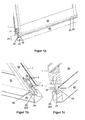
- FIG. 1 a shows a profile part 30 of a frame of a sliding leaf 1.
- the profile part 30 has on one side, which faces a guide rail 40, a receiving space 31.
- the receiving space 31 designed as a sliding shoe 20 guide part is partially received.
- the sliding block 20 protrudes in the direction of the guide rail 40.
- the guide rail 40 is formed in the direction of sliding sash 1 is substantially U-shaped, thus has on the inside a receptacle 41.
- To the leadership a guide portion 24 of the shoe 20 are formed in the guide rail 40 mutually parallel guide walls 42, of which only the front is visible.
- the guide section 24 has at its the guide walls 42 facing sides preferably sliding linings 26 of slippery material. Alternatively, the guide portion 24 itself is formed of such a material.
- the sliding shoe 20 has sliding linings 26 at both front ends. This makes it possible to use the frame profile 30 even with slightly curved or arcuately extending guide rails 40.
- the sliding leaf 1 can be moved even in the event of irregularities in the guide rail 40, since the guide section 24 in the region of missing sliding linings 26 to the facing guide wall 42 has a distance. If the guide section 24 is arc-shaped along its entire length, the guide rail 40 can define an arcuate travel path for the wing 1.
- FIG. 1b shows the arrangement of FIG. 1 a from a different perspective.
- the frame profile 30 of the wing 1 preferably adjoins a second frame profile part 50 at right angles and extends away from the guide rail 40.
- the frame profile part 50 is frontally mounted on the frame profile part 30 and secured by screws 2 to this.
- the guide section 24 of the sliding shoe 20 or its sliding linings 26 is / are guided guided along the guide walls 42 of the guide rail 40, which define the travel path of the sliding leaf 1.
- the guide portion 24 of the shoe 20 is provided on both sides with sliding linings 26. This is useful when the guide portion 24 slides along both guide walls 42. In addition is thus rattling of the shoe 20 in the guide rail 40 can be avoided.
- Figure 1c shows a similar arrangement, without frame profile part 50 and screws 2, 3.
- the guide portion 24 of the shoe 20 has by way of example only to the left here guide wall 42 toward a sliding coating 26. This solution lends itself when the sliding leaf 1 formed by means of the frame profile parts 50, 30 is pressed against a guide wall 42 only.
- Figure 1d shows the arrangement of FIG. 1 a without guide rail 40.
- the frame profile parts 50 are arranged on the front side at both ends on the frame profile part 30 or attached thereto and thus form the sliding leaf 1.
- the frame profile part 50 has a U-shaped recess 51, which is open in the direction of the sliding shoe 20.
- the recess 51 is designed so that the slide shoe 20 can be pushed into the frame profile part 30 at the front side even when the frame profile part 50 is mounted.
- the sliding linings 26 arranged here at both ends of the guide section 24 can be seen.
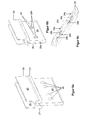
- Figure 1e shows the arrangement of Figure 1d without frame profile parts 50.
- the slide shoe 20 is received in the receiving space 31 by way of example approximately halfway.
- the sliding block 20 has two wall sections 21.
- the wall sections 21 extend away from the guide section 24 in the direction of the frame profile part 30. They are preferably substantially parallel formed to each other and also extend parallel to the longitudinal extent of the frame profile part 30th
- the wall portions 21 are preferably formed so as to taper towards each other. This facilitates the insertion or insertion of the shoe 20 from below in Figure 1e in the frame profile part 30th
- the wall portions 21 are formed thickened.
- the thickened portions extend towards one another, that is to say they have a smaller section than the wall sections 21 in the other area.
- the thickenings form a respective clamping section 23 and have such a distance between them that a receiving space is formed here in the form of a channel 4 for the screw 3.
- the receptacle thus formed is preferably circular.
- the maximum distance between the clamping portions 23 to each other is less than a maximum width or a maximum diameter of the thread of the screw 3. This makes it possible for the screw 3, with a screwing between the clamping portions 23 to the outside, ie in the direction corresponding wall portions 32 of To push frame section 30 or press.
- the clamping portions 23 thus come into contact with a respective one of the corresponding wall sections 32 of the frame profile part 30 and are preferably clamped with these. Ie. by simply screwing the screw 3 between the clamping portions 23 of the shoe 20 is securely fixed in the frame profile part 30.
- the sliding shoe 20 also faces in both directions each wall portion 32 each having a projection 27.
- the wall sections 32 have corresponding recesses 33.
- the projections 27 engage in the recesses 33.
- a tongue and groove connection is formed between the shoe 20 and the wall or clamping portions 21, 23 and the frame profile part 30 and its wall portions 32. Further preferably, this makes it possible to lock the sliding shoe 20 in the frame profile part 30.
- the projections 27 taper in the direction of end portions 22 of the sliding shoe 20 and thus form a run-on slope. This facilitates the impressions of the sliding shoe 20 in the frame profile part 30. Since the wall portions 21 have a certain distance from each other, the wall portions 21 during insertion of the shoe 20 in the frame profile part 30 upwards in Figure 1e compressed by this.
- the sliding linings 26, seen in the longitudinal extension of the frame profile part 30, preferably do not extend over the entire length of the guide section 24. They are preferably arranged or formed only at the front ends of the guide section 24. As a result, a cavity is created between the sliding linings 26, which are attached to a respective side of the guide section 24, and the guide rail (not shown), in which the guide section 24 is not guided along the guide rail 40.
- temperature fluctuations, the effects of weather or the like and thus possibly conditional changes in shape of the guide rail 40 or its guide walls 42 can be compensated. This improves the reliability with respect to the leadership of the sliding sash. 1
- An end section 25 of the sliding block 20 facing away from the frame profile part 30 is designed such that it at least partially covers a sliding lining 26 in the direction of the guide rail 40 (not shown). This serves the purpose of protecting the sliding linings 26 against mechanical damage within the guide rail 40. Due to the end portion 25, only this in the region of the guide rail 40 facing the end when inserting the guide portion 24 in the guide rail 40 come into contact with this, but not the sliding linings 26th
- the receiving openings 28 are exemplarily formed in the guide section 24, two of which are visible.
- the receiving openings 28 are formed in a direction transverse to the longitudinal extension of the sliding block 20 or to the travel path of the sliding block 20 and of the corresponding wing 1.
- the receiving openings 28 are preferably formed as through holes.
- the through holes 28 are used to attach the above-mentioned, at least one sliding layer 26. This is preferably done by means of mushroom-like locking heads 26b, which pass through a respective receiving opening 28 and the guide portion 24 preferably engage behind a detent 26 on the side facing away. They thus fix the sliding coating 26 on the guide section 24.
- the assembly is enormously simple; the sliding lining 26 is simply inserted with its locking heads 26 b in the associated receiving openings 28 and pushed to the detent point.
- FIG. 2 shows the guide rail 40 in greater detail.
- the cover walls 43 serve the optical cover, for example, a bottom rail into which the guide rail 40 may be inserted.
- wall sections 44 adjoin, which are preferably formed parallel to the cover walls 43 and extend away from one another.
- walls 45 are approximately at a right angle in the direction away from the cover walls 43.
- the wall sections 44, 45, 46 thus include a cavity which serves as a receptacle 41.
- the receptacle 41 thus has a width which is greater than a distance between the guide walls 42. Any dirt particles present in the guide rail 40 can thus avoid the sliding shoe 20, not shown, so that its mobility in the guide rail 40 is not or hardly affected. This increases the operational safety.
- the receptacle 41 is also preferably designed to be deeper than a maximum penetration depth of the shoe 20, with the same advantages.
- the guide rail 40 preferably has fastening openings 47 in the wall section 46.
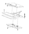
- FIG. 3 shows a guide assembly according to a second embodiment of the invention.
- the guide rail 40 is in a bottom rail 5 recorded, which is used in a ground, not shown.
- the cover walls 43 close the bottom rail 5 in the direction of wing 1 optically.
- the cover walls 43 even if not shown here, on the bottom rail 5 at.
- the guide rail 40 thus serves as an adapter piece for adapting the entire wing guide on any type of bottom rail 5.
- the wing 1 is effectively coupled via its guide rail 40 facing the frame profile part 30 with a driver assembly 6.
- the driver assembly 6 is passed between the guide walls 42 and taken in the receptacle 41 guided along the travel path.
- the driver assembly 6 opens into the receptacle 41 in a guide portion 24.
- the sliding linings 26 are exemplified by guide rollers 29 replaced as a guide part.
- the axis of rotation of the guide rollers 29 preferably runs parallel to the walls 45.
- the diameter of the guide rollers 29 is in each case smaller than the distance between the walls 45, 45 to each other. As a result, it is possible for each guide roller 29 to always roll along only one of the walls 45.
- FIG. 4 shows further areas of application of the guide arrangement according to the first embodiment de invention, ie with sliding block 20th
- FIG. 4a shows an arrangement with a fixed, here arranged on the left, and a movable wing 1.
- the movable wing 1 shown on the right is guided by means of the aforementioned shoe 20 in the guide rail 40, which is inserted into a bottom rail 5.
- the right-hand cover wall 43 is made shorter than the left-hand cover wall 43.
- the left-hand cover wall 43 bridges the distance between the left wing 1 or a seal 8 attached thereto and a bottom part 9 designed as an L-shaped profile possible to compensate for unevenness or distances between the wings 1 and the bottom 5, 9.
- FIG. 4b shows an arrangement which has two movable wings 1 and a fixed wing 1 arranged here on the left, which, as seen in Bebeungscardi, are arranged as an example in succession.
- Each movable wing 1 is provided with an associated bottom rail 5, which have a predetermined distance from each other.
- the guide rail 40 has two receptacles 41. This makes it possible to record two movable wings 1 guided in one and the same guide rail 40.
- the left cover wall 43 bridges a distance between the fixed wing 1 and bottom rail 5 or bottom part 9.
- the middle cover wall 43 connects the two receptacles 41 with each other.
- the movable wings 1, so the middle and the right, are taken guided by means of associated sliding shoes 20 in the associated receptacle 41.
- Figure 4c shows one too FIG. 4a similar arrangement.
- the cover walls 43 of the guide rail 40 may be identical to each other.
- the left cover wall 43 rests against the bottom part 9 and is thus also applicable to door systems which have no bottom rails 5.
- FIG. 4d shows one too FIG. 4b similar wing arrangement.
- the fixed wing 1 corresponds to the fixed wing 1 of Figure 4c ,
- each movable wing 1 is stored stored guided in a separate guide rail 40.
- Each guide rail 40 is exemplary according to Figure 4c educated. The visible here, possibly existing gap between the facing cover walls 43 of the guide rails 40 can be bridged, for example, with a filler.
- Figure 4e shows a wing assembly with, seen in the direction of travel, a movable wing 1, which is taken guided by a sliding block 20 in the associated guide rail 40.
- the guide rail 40 is not arranged in a bottom rail 5 but attached directly to a floor 10. The attachment takes place for example by means of screwing the cover walls 43 with a wing 1 facing surface of the bottom 10. This arrangement makes it possible to compensate for uneven floors, for example by means of intermediately mounted compensating elements.
- the invention is readily applicable to wing systems that do not have a bottom rail 5 or the like.
- FIG. 4f shows one too Figure 4e similar leadership arrangement. However, this lacks the cavity for insertion of the guide rail 40. Rather, this is sunk directly into the bottom, not shown, so at the same time has the function of the aforementioned bottom rail 5.
- the wing 1 is exemplified as a framed glass wing.
- FIG. 5a shows a guide assembly according to a third embodiment of the invention. It corresponds essentially to the previous embodiment, with the difference that the guide portion 24 is not formed continuously. Rather, here two sliding shoes 20 are each used on the front side in the frame profile part 30. This simplifies the insertion of the sliding shoes 20 into the frame profile 30, since they do not have to be pushed through the entire frame profile part 30 therethrough.
- the wall portions 21 and / or the clamping portions 23 are formed continuously. This allows relatively short surfaces to slidably operatively connect to the guide rail 40. This promotes the application on arcuate or otherwise curved guide rails 40 and thus travel paths.
- FIG. 5b shows the arrangement without guide rail 40 in a modification.
- two sliding shoes 20 are used, each provided with only one sliding coating 26. This facilitates the insertion of the remaining shoe 20 due to its short training.
- FIG. 6 shows one of the sliding shoes 20 of FIG. 5b in greater detail.
- FIG. 6a shows the sliding block 20 without sliding linings 26.
- four receiving openings 28 are formed in the guide section 24, which are formed in a direction transverse to the longitudinal extension of the sliding block 20 or to the travel of the sliding block 20 and the corresponding wing 1.
- the receiving openings 28 are preferably formed as through holes and are used to attach the above-mentioned, at least one sliding coating 26.
- the wall sections 21 and the projections 27 are clearly visible.
- FIG. 6b shows the sliding block 20, provided with a sliding coating 26.
- the sliding lining 26 has a guide or sliding plate 26a, which preferably rests in the assembled state, not shown on the guide portion 24 of the shoe 20. Furthermore, the sliding lining 26 has projections 26b. By way of example, two projections 26b are formed, which in the assembled state correspond to respective receiving openings 28 of the guide section 24. In the example shown, the locking projections, from the left in FIG. 6 seen, inserted into the second and the fourth receiving opening 28 of the guide portion 24.
- the projections 26b are exemplarily designed as latching heads, which are pressed through the latter during insertion into the respective receiving opening 28 and in the assembled state the guide plate 26 facing away from the side of the guide portion 24 engage behind and thus engage with the guide portion 24.
- the mushroom-like latching heads 26b project in the assembled state over the guide section 24 of the sliding block 20.
- FIG. 6c shows the case of two oppositely mounted on the sliding block 20, not shown sliding linings 26. It serves to represent the position of these two sliding linings 26 to each other.
- 26 recesses 26 c are formed in each sliding coating. As can be seen, the recesses 26c of a sliding lining 26 are aligned with corresponding locking heads 26b of the other, opposing sliding shoe 20.
- the recesses 26c are groove-like in the example shown. The grooves are continuously formed or terminate in the region of the corresponding latching heads 26c of the other sliding lining 26.
- the recesses 26c are formed as circular recesses.
- FIG. 6d shows the arrangement of the aforementioned shoe 20 in an exploded view.
- the left sliding lining 26 is mounted by its locking heads 26 b from the left through, from below in FIG. 6d counted, the first and the third receiving opening 28 of the guide portion 24 are inserted and latched, as indicated by the two associated dashed lines.
- the right sliding pad 20 is now mounted by its locking heads 26 b coming from the right coming through the second and the fourth receiving opening 28 are inserted and latched, as indicated by the other two dashed lines.
- the latching heads 26b automatically reach the corresponding recess 26c of the opposite sliding lining 20.
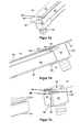
- FIG. 7 shows a guide rail 40 according to a second embodiment of the invention.
- at least one end cap 60 is placed on the guide rail 40 on the front side.
- the attachment of the end cap 60 to the guide rail 40 can usually be done for example by means of jamming, screwing, rattling or the like.
- the end cap 60 has a cover section 61, which preferably terminates flush with the cover walls 43, not shown in the direction of the wing 1, of the guide rail 40.
- the end cap 60 also has a recess which serves as a receptacle 62 for a guide roller, not shown. This makes it possible to use a guide roller, not shown, in the guide rail 40.
- the end cap 60 is preferably pushed during assembly along a longitudinal extent of the guide rail 40 on the end face.
- the end cap 60 preferably has a stop 63, which is designed such that, when the end cap 60 is pushed onto the guide rail 40, it is at some point here against an associated cover wall 43 encounters. In this state, the end cap 60 can not be pushed further onto the guide rail 40.
- the end cap 60 further has a hollow-shaped section in the form of a hose nozzle 64 facing away from the wing 1 and formed inside. This is used for discharging, for example, rainwater from the guide rail 40.
- the arrangement can be used for example in a wet and / or outdoor area.
- the hose nozzle 64 serves to connect, for example, a drainage hose or the like. But it can also be designed as a drain pipe or pipe itself.
- FIG. 7b shows the arrangement from a different perspective.
- the enclosing of the guide rail 40 is clearly visible from the end cap 60. This is done by means of walls 65-69, which have an inner contour which is preferably complementary to the outer contour of the walls 42, 43, 44 (not visible), 45 and 46 is formed.
- the end cap 60 is clamped on the guide rail 40. Furthermore, the flush closing of the cover walls 43 with the cover 61 can be seen.
- FIG. 7c shows the arrangement of FIG. 7b in an exploded view.
- the formation of the stop 63 is particularly easy to recognize. It is exemplarily formed by means of a single, in the direction of guide rail 40 facing surface, which is formed mainly in the receptacle 62 and preferably hugs the inside walls 61 and 65 - 69.
- the above-described sliding block 20 may additionally or alternatively also have one or more guide rollers 29 instead of the guide section 24 with sliding lining 26.
- the driver assembly 6 have sliding linings 26.
- the guide rail 40 can be used, for example, in a mounting rail arranged above the wing 1, which receives the weight of the wing 1.
- the wing 1 can of course also be carried in the aforementioned bottom rail 5, for example by means of rollers.
- the aforementioned guide parts that is to say the sliding shoe 20 or the guide roller 29 mounted on the driver assembly 6 in a freely rotatable manner, can instead also be used, for example, centrally in the wing 1 or the frame profile part 30 instead of the front side.
- the screw 3 can provide a screw head with Phillips or hexagon socket, torx-like or the like may be formed so that the installer can screw the screw relatively easily in this mounting position.
- one or more guide parts 6, 20 or a guide part 6, 20 are possible per wing 1, depending on how the guide should fail.
- a single or more than two sliding shoes 20 and guide rollers 29 may be formed or attached.
Landscapes
- Engineering & Computer Science (AREA)
- Mechanical Engineering (AREA)
- Support Devices For Sliding Doors (AREA)
- Bearings For Parts Moving Linearly (AREA)
- Supports For Pipes And Cables (AREA)
Applications Claiming Priority (2)
| Application Number | Priority Date | Filing Date | Title |
|---|---|---|---|
| DE202009016563 | 2009-12-08 | ||
| DE102009058922A DE102009058922A1 (de) | 2009-12-08 | 2009-12-17 | Führung für einen Schiebeflügel |
Publications (2)
| Publication Number | Publication Date |
|---|---|
| EP2333213A2 true EP2333213A2 (fr) | 2011-06-15 |
| EP2333213A3 EP2333213A3 (fr) | 2014-05-07 |
Family
ID=43500176
Family Applications (1)
| Application Number | Title | Priority Date | Filing Date |
|---|---|---|---|
| EP10013398.2A Withdrawn EP2333213A3 (fr) | 2009-12-08 | 2010-10-07 | Guide pour ouvrant coulissant |
Country Status (2)
| Country | Link |
|---|---|
| EP (1) | EP2333213A3 (fr) |
| DE (1) | DE102009058922A1 (fr) |
Families Citing this family (2)
| Publication number | Priority date | Publication date | Assignee | Title |
|---|---|---|---|---|
| DE102014222450B3 (de) * | 2014-11-04 | 2016-01-07 | Geze Gmbh | Befestigungssystem für eine integrierte Gleitschiene |
| DE102017123074A1 (de) | 2017-10-05 | 2019-04-11 | Agtatec Ag | Automatisches Türsystem, insbesondere in Form einer Schiebetür oder einer Teleskopschiebetür oder einer Falttür |
Citations (1)
| Publication number | Priority date | Publication date | Assignee | Title |
|---|---|---|---|---|
| DE19500067A1 (de) | 1995-01-03 | 1996-09-12 | Hoermann Genk N V | Kipptor |
Family Cites Families (2)
| Publication number | Priority date | Publication date | Assignee | Title |
|---|---|---|---|---|
| US1971098A (en) * | 1931-06-04 | 1934-08-21 | Tyler Co W S | Door guide |
| AU414120B2 (en) * | 1965-10-15 | 1971-06-16 | Clive Investments Pty. Limited | Roller or sheave block |
-
2009
- 2009-12-17 DE DE102009058922A patent/DE102009058922A1/de not_active Withdrawn
-
2010
- 2010-10-07 EP EP10013398.2A patent/EP2333213A3/fr not_active Withdrawn
Patent Citations (1)
| Publication number | Priority date | Publication date | Assignee | Title |
|---|---|---|---|---|
| DE19500067A1 (de) | 1995-01-03 | 1996-09-12 | Hoermann Genk N V | Kipptor |
Also Published As
| Publication number | Publication date |
|---|---|
| DE102009058922A1 (de) | 2011-06-09 |
| EP2333213A3 (fr) | 2014-05-07 |
Similar Documents
| Publication | Publication Date | Title |
|---|---|---|
| EP2085559B1 (fr) | Dispositif d'étanchéité abaissable | |
| DE202014009250U1 (de) | Dichtungsvorrichtung für einen verschiebbaren Flügel als Schiebeflügel oder verschiebbaren Hebe-Schiebeflügel eines Fensters oder einer Tür | |
| EP3417134B1 (fr) | Ensemble ferrure pour le raccordement d'un battant coulissant et basculant | |
| DE202022100517U1 (de) | Profilanordnung eines Fensters oder einer Tür mit einem Flügelprofil, insbesondere einem Schiebeflügelprofil | |
| DE102011011113A1 (de) | Rahmensystem eines Partikelschutzgitters | |
| EP1893834B1 (fr) | Dispositif d'ouverture de porte electrique pour portes en verre | |
| EP3392443A1 (fr) | Kit de montage de volet roulant pour une fenêtre de toit, fenêtre de toit avec un tel kit et procédé de montage d'un volet roulant à une fenêtre de toiture à l'aide d'un tel kit | |
| EP1439278A2 (fr) | Joint, notamment joint de contact ou joint automatiquement abaissable pour portes avec support adjustable | |
| EP2951374B1 (fr) | Pièce coulissante servant à guider une partie de meuble dans un sens de guidage sur une glissière et ferrure de meuble | |
| DE202016102808U1 (de) | Möbel mit einem an einem Laufprofil verfahrbaren Schiebeelement und einer Führungseinrichtung | |
| EP2333213A2 (fr) | Guide pour ouvrant coulissant | |
| AT512327B1 (de) | Hebe/schiebetür | |
| DE29600334U1 (de) | Magnetische Türdichtung und Zusatzprofile zu deren Herstellung | |
| DE102016216835A1 (de) | Aushebesicherung für einen verschiebbaren und zum Verschieben anhebbaren Flügel | |
| DE102008006800B4 (de) | Führungsvorrichtung für einen Schiebeflügel | |
| EP3792444B1 (fr) | Profil de fixation pour un joint inférieur d'une lamelle de vantail de porte, lamelle inférieure pour vantail de porte et porte équipée d'une telle lamelle | |
| EP1733113A1 (fr) | Cassette pour la transmission de force dans un leve-vitre | |
| DE19819366A1 (de) | Türschwelle und Sockelprofil zum Zusammenwirken mit der Türschwelle | |
| DE102014111131A1 (de) | Vorrichtung zur Ver- und Entriegelung eines Fensterflügels, einer Lüftungsklappe oder dergleichen an einem Blendrahmen | |
| DE102012100654A1 (de) | Gleitstück, Gleitschiene und damit versehene Gleitschienenanordnung für Gleitschienengestänge sowie Türbetätiger | |
| EP0809339B1 (fr) | Appareil pour installation électrique | |
| DE19534648A1 (de) | Feststellvorrichtung für einen Schwenkflügel | |
| EP1126121A2 (fr) | Profilé de cadre en plusieurs parties | |
| EP0945574B1 (fr) | Charnière pour portes, fenêtres ou similaires | |
| DE102017125608B3 (de) | Bandteil und System mit einem Bandteil und mit einem Profil |
Legal Events
| Date | Code | Title | Description |
|---|---|---|---|
| PUAI | Public reference made under article 153(3) epc to a published international application that has entered the european phase |
Free format text: ORIGINAL CODE: 0009012 |
|
| AK | Designated contracting states |
Kind code of ref document: A2 Designated state(s): AL AT BE BG CH CY CZ DE DK EE ES FI FR GB GR HR HU IE IS IT LI LT LU LV MC MK MT NL NO PL PT RO RS SE SI SK SM TR |
|
| AX | Request for extension of the european patent |
Extension state: BA ME |
|
| PUAL | Search report despatched |
Free format text: ORIGINAL CODE: 0009013 |
|
| AK | Designated contracting states |
Kind code of ref document: A3 Designated state(s): AL AT BE BG CH CY CZ DE DK EE ES FI FR GB GR HR HU IE IS IT LI LT LU LV MC MK MT NL NO PL PT RO RS SE SI SK SM TR |
|
| AX | Request for extension of the european patent |
Extension state: BA ME |
|
| RIC1 | Information provided on ipc code assigned before grant |
Ipc: E05D 15/06 20060101AFI20140328BHEP |
|
| 17P | Request for examination filed |
Effective date: 20141031 |
|
| RBV | Designated contracting states (corrected) |
Designated state(s): AL AT BE BG CH CY CZ DE DK EE ES FI FR GB GR HR HU IE IS IT LI LT LU LV MC MK MT NL NO PL PT RO RS SE SI SK SM TR |
|
| 17Q | First examination report despatched |
Effective date: 20150303 |
|
| RAP1 | Party data changed (applicant data changed or rights of an application transferred) |
Owner name: DORMA DEUTSCHLAND GMBH |
|
| STAA | Information on the status of an ep patent application or granted ep patent |
Free format text: STATUS: THE APPLICATION IS DEEMED TO BE WITHDRAWN |
|
| 18D | Application deemed to be withdrawn |
Effective date: 20150714 |