EP2336423A2 - Elément d'amortissement pour la construction de voies ferrées ayant une couche de glissement, système de rails pour voie ferrée doté d'un élément d'amortissement et procédé de fabrication d'un élément d'amortissement - Google Patents
Elément d'amortissement pour la construction de voies ferrées ayant une couche de glissement, système de rails pour voie ferrée doté d'un élément d'amortissement et procédé de fabrication d'un élément d'amortissement Download PDFInfo
- Publication number
- EP2336423A2 EP2336423A2 EP10194582A EP10194582A EP2336423A2 EP 2336423 A2 EP2336423 A2 EP 2336423A2 EP 10194582 A EP10194582 A EP 10194582A EP 10194582 A EP10194582 A EP 10194582A EP 2336423 A2 EP2336423 A2 EP 2336423A2
- Authority
- EP
- European Patent Office
- Prior art keywords
- damping element
- rail
- sliding layer
- layer
- wear
- Prior art date
- Legal status (The legal status is an assumption and is not a legal conclusion. Google has not performed a legal analysis and makes no representation as to the accuracy of the status listed.)
- Granted
Links
Images

Classifications
-
- E—FIXED CONSTRUCTIONS
- E01—CONSTRUCTION OF ROADS, RAILWAYS, OR BRIDGES
- E01B—PERMANENT WAY; PERMANENT-WAY TOOLS; MACHINES FOR MAKING RAILWAYS OF ALL KINDS
- E01B9/00—Fastening rails on sleepers, or the like
- E01B9/68—Pads or the like, e.g. of wood, rubber, placed under the rail, tie-plate, or chair
-
- E—FIXED CONSTRUCTIONS
- E01—CONSTRUCTION OF ROADS, RAILWAYS, OR BRIDGES
- E01B—PERMANENT WAY; PERMANENT-WAY TOOLS; MACHINES FOR MAKING RAILWAYS OF ALL KINDS
- E01B9/00—Fastening rails on sleepers, or the like
- E01B9/68—Pads or the like, e.g. of wood, rubber, placed under the rail, tie-plate, or chair
- E01B9/681—Pads or the like, e.g. of wood, rubber, placed under the rail, tie-plate, or chair characterised by the material
- E01B9/683—Pads or the like, e.g. of wood, rubber, placed under the rail, tie-plate, or chair characterised by the material layered or composite
-
- E—FIXED CONSTRUCTIONS
- E01—CONSTRUCTION OF ROADS, RAILWAYS, OR BRIDGES
- E01B—PERMANENT WAY; PERMANENT-WAY TOOLS; MACHINES FOR MAKING RAILWAYS OF ALL KINDS
- E01B9/00—Fastening rails on sleepers, or the like
- E01B9/68—Pads or the like, e.g. of wood, rubber, placed under the rail, tie-plate, or chair
- E01B9/685—Pads or the like, e.g. of wood, rubber, placed under the rail, tie-plate, or chair characterised by their shape
Definitions
- the present invention relates to a damping element for track construction, which in particular a rail intermediate layer is to be understood, which is arranged between a railway sleeper and a vibration-damping rail track to be stored on the railway sleeper.
- the invention further relates to a railroad track system which includes such a damping element, and to a method for producing such a damping element.
- damping elements or rail pads generally serve the elastic coupling between the railroad track, hereinafter referred to as “rail”, and railroad tie, hereinafter referred to as “threshold”.
- rail generally serve the elastic coupling between the railroad track, hereinafter referred to as “rail”, and railroad tie, hereinafter referred to as “threshold”.
- threshold railroad tie
- a rail already laid on the threshold is welded at intervals of about 150 m.
- the rail Prior to welding, the rail must be pre-tensioned so that the rail does not experience any distortion, even with large temperature changes. For the tension, it is necessary to pull the ends of the rails from a few cm up to about 3 m.
- damping elements which are made of a soft material and thus - especially at higher temperatures - have a high coefficient of friction often occurs the problem on, that these out of the space between the rail and the lock out or be pulled out.
- the present invention seeks to provide a damping element for track construction for arrangement between a railway sleeper and a railroad track, on the one hand good elastic deflection of the rail and on the other hand allows good decoupling between rail and threshold, without thereby in track construction There is a significant risk that the damping element from the gap between the rail and the threshold moves out or is pulled out. Furthermore, it is an object of the invention to provide a rail track system which includes a damping element as indicated above. In addition, a method is to be specified with which a damping element described above can be produced.
- an untreated material of the damping element is hereinafter referred to as such material to which no special surface treatment methods have been applied and in which no further additives or reinforcements, to achieve over elasticity and vibration damping properties were added.
- the damping element provided for the track construction in particular a rail intermediate layer which is to be arranged between a railway sleeper and a rail track to be supported vibration-damped on the railway sleeper, has a first contact surface which, in the assembled state, comes into contact with the rail track and is designed such that it serves as a friction-reducing sliding layer.
- “Reibungsmindernd” means here that arranged thereon or fixed rail track with as low as possible - but at least less than would be the case with untreated material of the damping element - friction can move or move on the damping element.
- the sliding layer so that it has a low roughness or roughness compared to the untreated material of the damping element, in other words is smooth.
- the friction surface can be reduced by local elevations, beads or nubs, or depressions, the friction surface, so that thereby the resulting total friction force is reduced because elastomers do not follow the Coulomb's friction law.
- the height of the elevations or recesses in the range of about 0.1 to 0.5 mm.
- the sliding layer is applied to the surface of the damping element, without the underlying material of the damping element is changed or needs to be changed.
- a damping element can be manufactured in a simple and cost-effective manner.
- a particularly simply constructed damping element can be obtained in that the sliding layer contains soap suds, silicone-containing liquid, lubricating varnish or a mixture of these substances, the application of these substances being carried out, for example, by spraying, rolling or brushing.
- the overlay can also be formed by flocking with short staple textile fibers of cotton, polyamide (PA) or polyester (PETP).
- the sliding layer is formed of hard rubber and is optionally provided with an internal lubricant, for example of a medium incompatible with a polymer matrix (for example aromatic / naphthenic oils, such as LOXAMID®).
- an internal lubricant for example of a medium incompatible with a polymer matrix (for example aromatic / naphthenic oils, such as LOXAMID®).
- the sliding layer can also be made of plastic (eg. PE, PP, PA, PETP or PTFE), fabric (for example, PA fabric) and / or metal (such as sheet metal).
- the sliding layer is formed by subsequent modification of the surface, such as by halogenation and / or fluorination. Flaming or plasma or corona treatment is also possible.
- the sliding layer can be formed.
- the sliding layer is formed from a combination of the substances explained above.
- the damping element has a second contact surface, with which it rests on the railroad tie and which is formed as a wear-resistant, so subject to low wear, or resistant to wear resistant layer.
- wear is preferably wear by friction (abrasion) seen, which takes place when the damping element translationally moves relative to the railway sleeper or at the moment of crossing a train and the vertical forces occurring in the horizontal direction, ie in the plane of contact surface to the railway sleeper , expands and so the outer parts of the damping element are translationally moved against the railway sleeper.
- the wear-resistant layer characterized in that it compared to the untreated material of the damping element, preferably elastomer, is less affected by friction, abrasion or similar wear mechanisms.
- the object underlying the invention is also achieved with a rail track system comprising a railway sleeper, a railway rail mounted on the railroad track rail and a damping element according to the above description, which is arranged between the railway sleeper and the railroad track and whose sliding layer bears against the railroad track.
- a railway track system is reliably ensured by the slippery layer provided on the damping element, that the damping element is not pulled out of the space between the railroad track and the railroad tie at the track construction.
- the object underlying the invention is achieved by a method for producing a damping element for track construction, which is characterized in that a friction-reducing sliding layer is formed on a first contact surface of the damping element.
- This friction-reducing sliding layer is advantageously formed by a two-component injection molding, ie in the same manufacturing step as the damping element.
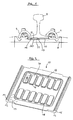
- the rail 8 undergoes a relative movement to the damping element 10, for example in track construction or due to temperature and associated changes in length, it can easily slide on the sliding layer 22 due to the sliding layer 22 of the damping element 10, since the sliding layer 22 is designed to reduce friction, ie represents a friction pairing with the rail 8 with a low coefficient of friction.
- the sliding layer 22 is designed to reduce friction, ie represents a friction pairing with the rail 8 with a low coefficient of friction.
- the friction-reducing sliding layer can be advantageously formed by a modification of the surface, such as by chlorination or fluorination.
- the sliding layer of hard rubber possibly with the addition of an internal lubricant
- plastic, fabric or metal be formed or contain one or more of these substances.
- a low-wear layer 32 is formed, precisely between the lower nubs 17, and depressions.
- the wear layer 32 ensures that even if the rail 8 despite the sliding layer 22, the damping element 10 moves with a movement of the rail 8, the damping element 10 is not or not strongly worn by the corresponding movement on the threshold 6 and therefore only subject to extremely low wear. Thus, it rarely or even never needs to be replaced for wear reasons.
- the low-wear layer 32 may be formed of plastic, fabric, and / or PU paint and also contain a wear protection mixture.
- the friction-reducing sliding layer 22 and the low-wear layer 32 may be arranged not only in regions on the respective designated contact surfaces 20 and 30 or in other areas arranged, but also over the entire surface, that is, the sliding layer 22 and the low-wear layer 32 on the entire or at least substantially the entire surface of the damping element 10 extend.
- Fig. 2 shows in perspective from below a second embodiment of the damping element 10 according to the invention, which differs from the first embodiment in that it has only upper nubs, or elevations 18.
- a low-wear layer 32 is provided at the bottom of the nubs, or elevations 18 and at the bottom of a border 19, which has the same vertical extent as the nubs 18 (see also Fig. 4 ).
- a low-wear layer 32 is disposed at those surfaces of the underside of the damping element 10, which come to rest on a railroad tie, not shown, while at those locations of the underside of the damping element 10, where neither knobs, or elevations 18 nor the Outline 19 are provided, no low-wear layer 32 is present.
- a low-wear layer 32 is shown only on a nub, or elevation 18. This ensures that wherever the damping element 10 is in contact with the threshold 6, the low-wear layer 32 is provided.
- a projection 14 or 15 projects downwards - ie at a substantially right angle to the extension direction of the damping element 10.
- These projections 14, 15 are designed so that they By means of these rib-like projections 14, 15 an additional contribution is made that the damping element 10 can not be pulled out of the gap between the rail 8 and the sill 6. From the illustration from Fig. 3 it can be seen that the upper surface of the damping element 10, which forms a contact surface 20 to the overlying rail 8, a friction-reducing sliding layer 22 is formed with a substantially rectangular shape.
- Type and application of the friction-reducing sliding layer 22 and the low-wear layer 32 in this embodiment can basically exactly as in the first embodiment and therefore need no further explanation.
- the damping element 10 can be produced by means of a two-component injection molding process, in which the friction-reducing sliding layer is produced together with the main body of the damping element 10-ie, the damping element 10 without additional layers. If, in addition to the sliding layer 22, a low-wear layer 32 is to be produced, the use of a three-component injection molding process is appropriate. However, it is also possible for the sliding layer 22 and / or the low-wear layer 32 to be subsequently applied only after the basic body of the damping element 10 has been produced.
- the main body of the damping element 10 is usually made of a rubber in a suitable Shore hardness.
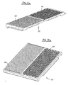
- Figs. 5a and 5b show a further preferred exemplary embodiments of a damping element 10 according to the invention in these a defined surface structure is provided depending on the nature of the rail underside (eg. According to VDI 3400, electric discharge process). Furthermore, the friction surface is reduced by local elevations 40 (for example in the form of beads or nubs), as a result of which the resulting total friction force is reduced since elastomers do not follow the Coulomb friction law. Particularly advantageously, the height of the elevations or corresponding recesses in the range of about 0.1 to 0.5 mm.
Landscapes
- Engineering & Computer Science (AREA)
- Mechanical Engineering (AREA)
- Architecture (AREA)
- Civil Engineering (AREA)
- Structural Engineering (AREA)
- Railway Tracks (AREA)
- Vibration Prevention Devices (AREA)
Applications Claiming Priority (1)
| Application Number | Priority Date | Filing Date | Title |
|---|---|---|---|
| DE102009055070.4A DE102009055070B4 (de) | 2009-12-21 | 2009-12-21 | Dämpfungselement für den Gleisbau mit Gleitschicht und ein Eisenbahnschienensystem mit Dämpfungselement |
Publications (3)
| Publication Number | Publication Date |
|---|---|
| EP2336423A2 true EP2336423A2 (fr) | 2011-06-22 |
| EP2336423A3 EP2336423A3 (fr) | 2013-09-25 |
| EP2336423B1 EP2336423B1 (fr) | 2020-04-29 |
Family
ID=43769101
Family Applications (1)
| Application Number | Title | Priority Date | Filing Date |
|---|---|---|---|
| EP10194582.2A Active EP2336423B1 (fr) | 2009-12-21 | 2010-12-10 | Elément d'amortissement pour la construction de voies ferrées ayant une couche de glissement, système de rails pour voie ferrée doté d'un élément d'amortissement et procédé de fabrication d'un élément d'amortissement |
Country Status (2)
| Country | Link |
|---|---|
| EP (1) | EP2336423B1 (fr) |
| DE (1) | DE102009055070B4 (fr) |
Cited By (3)
| Publication number | Priority date | Publication date | Assignee | Title |
|---|---|---|---|---|
| WO2014177419A1 (fr) * | 2013-04-29 | 2014-11-06 | Semperit Ag Holding | Assiette de rail |
| EP3546649A1 (fr) * | 2018-03-27 | 2019-10-02 | Semperit AG Holding | Couche intermédiaire destinée à être agencée entre un rail et un seuil, et son procédé de fabrication |
| EP3546650A1 (fr) * | 2018-03-27 | 2019-10-02 | Semperit AG Holding | Système, procédé, dispositif et traverse pour maintenir un rail |
Families Citing this family (5)
| Publication number | Priority date | Publication date | Assignee | Title |
|---|---|---|---|---|
| DE102014216543A1 (de) * | 2014-08-20 | 2016-02-25 | Semperit Ag Holding | Zwischenlage |
| CN107366200B (zh) * | 2017-08-03 | 2023-08-15 | 华东交通大学 | 一种颗粒阻尼耗能减振道砟垫 |
| DE102018100837A1 (de) | 2018-01-16 | 2019-07-18 | Vossloh-Werke Gmbh | Zwischenplatte zur Anordnung zwischen einem Untergrund und einer Schiene für ein Schienenfahrzeug in einem Schienenbefestigungspunkt sowie Schienenbefestigungspunkt |
| DE102021117800A1 (de) | 2021-07-09 | 2023-01-12 | Semperit Ag Holding | Zwischenlage, System zur Befestigung einer Zwischenlage auf einer Bahnschwelle und Verfahren zur Herstellung einer Zwischenlage |
| CN113931016A (zh) * | 2021-10-28 | 2022-01-14 | 株洲时代新材料科技股份有限公司 | 一种轨道减震器 |
Family Cites Families (6)
| Publication number | Priority date | Publication date | Assignee | Title |
|---|---|---|---|---|
| DE2817533C2 (de) * | 1978-04-21 | 1984-10-11 | Krauss-Maffei AG, 8000 München | Schienenanordnung |
| DE19623523A1 (de) | 1996-06-13 | 1998-01-02 | Vorwerk & Sohn | Vorrichtung zur Auflagerung von Schienen, insbesondere Eisenbahnschienenauflager |
| GB2334738A (en) | 1998-02-28 | 1999-09-01 | Glynwed Pipe Systems Ltd | Rail pad |
| DE102004008633A1 (de) | 2004-02-21 | 2005-09-08 | Ks Gleitlager Gmbh | Gleitlagerverbundwerkstoff |
| DE202006008104U1 (de) | 2006-05-18 | 2006-07-20 | Seifert, Dietrich | Vorrichtung zur Vibrations- und Schalldämpfung von an Betonfundamenten befestigten Schienen für Züge, insbesondere Hochgeschwindigkeitszüge |
| DE102008007495A1 (de) * | 2008-02-05 | 2009-08-06 | Semperit Ag Holding | Unterlegplatte und Verfahren zu deren Herstellung |
-
2009
- 2009-12-21 DE DE102009055070.4A patent/DE102009055070B4/de not_active Expired - Fee Related
-
2010
- 2010-12-10 EP EP10194582.2A patent/EP2336423B1/fr active Active
Non-Patent Citations (1)
| Title |
|---|
| None |
Cited By (4)
| Publication number | Priority date | Publication date | Assignee | Title |
|---|---|---|---|---|
| WO2014177419A1 (fr) * | 2013-04-29 | 2014-11-06 | Semperit Ag Holding | Assiette de rail |
| US9932711B2 (en) | 2013-04-29 | 2018-04-03 | Semperit Ag Holding | Rail pad |
| EP3546649A1 (fr) * | 2018-03-27 | 2019-10-02 | Semperit AG Holding | Couche intermédiaire destinée à être agencée entre un rail et un seuil, et son procédé de fabrication |
| EP3546650A1 (fr) * | 2018-03-27 | 2019-10-02 | Semperit AG Holding | Système, procédé, dispositif et traverse pour maintenir un rail |
Also Published As
| Publication number | Publication date |
|---|---|
| DE102009055070B4 (de) | 2022-10-20 |
| EP2336423B1 (fr) | 2020-04-29 |
| DE102009055070A1 (de) | 2011-06-22 |
| EP2336423A3 (fr) | 2013-09-25 |
Similar Documents
| Publication | Publication Date | Title |
|---|---|---|
| EP2336423B1 (fr) | Elément d'amortissement pour la construction de voies ferrées ayant une couche de glissement, système de rails pour voie ferrée doté d'un élément d'amortissement et procédé de fabrication d'un élément d'amortissement | |
| DE202009001963U1 (de) | Auszugsführung | |
| DE102010009141A1 (de) | Kraftfahrzeugschloss mit geräuscharmem Schlossbügel | |
| EP2990529B1 (fr) | Couche intermediaire | |
| AT511068B1 (de) | Vorrichtung zur schwingungsdämpfung und zur veränderung der longitudinalen steifigkeit | |
| WO2013117325A1 (fr) | Tronçon de voie pour un rail ainsi que procédé pour améliorer le montage élastique | |
| DE202013007959U1 (de) | Türkämpfer für eine Aufzugstür | |
| DE102011052557A1 (de) | Sektionaltor | |
| DE102010024509A1 (de) | Schloss für Kraftfahrzeuge oder Gebäude mit gesondert behandelten Kontaktzonen | |
| DE102008052152A1 (de) | Weichenzungenhebe- und Rollvorrichtung | |
| DE202009001787U1 (de) | Kontinuierliche elastische Lagerung von Straßenbahnschienen, insbesondere im Weichenbereich | |
| EP4325012A1 (fr) | Dispositif de guidage pour porte coulissante et pivotante sans rail de guidage | |
| DE102015211220B4 (de) | Dachteileinheit für ein Kraftfahrzeug-Schiebedachsystem | |
| DE10116992C1 (de) | Kunststoffgleitplatte für Schienenweichen | |
| EP2173504B1 (fr) | Machine à laminer des profilés | |
| DE202014100928U1 (de) | Blockschloss mit Freistich | |
| EP2722440B1 (fr) | Élément de profilé | |
| DE102007050475A1 (de) | Führungswagen für ein Linearwälzlager und Verwendung des Führungswagens | |
| EP2018487B1 (fr) | Roulement linéaire | |
| EP1247901A2 (fr) | Selle de glissement pour aiguillages ferroviaires | |
| WO2024213609A1 (fr) | Système télescopique et élément de précharge | |
| EP4371921A1 (fr) | Patin de guidage coulissant pour ascenseur | |
| DE102011017757B4 (de) | Konzept zum Abdichten einer Linearführung | |
| DE102010024508A1 (de) | Schlosshalter für Schlösser in Kraftfahrzeugen und Gebäuden mit eine Einschnürung aufweisendem Schließbolzen | |
| DE102011002796A1 (de) | Trägerelement für die Aufnahme in einem Zug- oder Lastträgergurt |
Legal Events
| Date | Code | Title | Description |
|---|---|---|---|
| PUAI | Public reference made under article 153(3) epc to a published international application that has entered the european phase |
Free format text: ORIGINAL CODE: 0009012 |
|
| AK | Designated contracting states |
Kind code of ref document: A2 Designated state(s): AL AT BE BG CH CY CZ DE DK EE ES FI FR GB GR HR HU IE IS IT LI LT LU LV MC MK MT NL NO PL PT RO RS SE SI SK SM TR |
|
| AX | Request for extension of the european patent |
Extension state: BA ME |
|
| PUAL | Search report despatched |
Free format text: ORIGINAL CODE: 0009013 |
|
| AK | Designated contracting states |
Kind code of ref document: A3 Designated state(s): AL AT BE BG CH CY CZ DE DK EE ES FI FR GB GR HR HU IE IS IT LI LT LU LV MC MK MT NL NO PL PT RO RS SE SI SK SM TR |
|
| AX | Request for extension of the european patent |
Extension state: BA ME |
|
| RIC1 | Information provided on ipc code assigned before grant |
Ipc: E01B 9/68 20060101AFI20130819BHEP |
|
| 17P | Request for examination filed |
Effective date: 20140304 |
|
| RBV | Designated contracting states (corrected) |
Designated state(s): AL AT BE BG CH CY CZ DE DK EE ES FI FR GB GR HR HU IE IS IT LI LT LU LV MC MK MT NL NO PL PT RO RS SE SI SK SM TR |
|
| 17Q | First examination report despatched |
Effective date: 20151026 |
|
| 17Q | First examination report despatched |
Effective date: 20151030 |
|
| STAA | Information on the status of an ep patent application or granted ep patent |
Free format text: STATUS: EXAMINATION IS IN PROGRESS |
|
| GRAP | Despatch of communication of intention to grant a patent |
Free format text: ORIGINAL CODE: EPIDOSNIGR1 |
|
| STAA | Information on the status of an ep patent application or granted ep patent |
Free format text: STATUS: GRANT OF PATENT IS INTENDED |
|
| INTG | Intention to grant announced |
Effective date: 20191213 |
|
| GRAS | Grant fee paid |
Free format text: ORIGINAL CODE: EPIDOSNIGR3 |
|
| GRAA | (expected) grant |
Free format text: ORIGINAL CODE: 0009210 |
|
| STAA | Information on the status of an ep patent application or granted ep patent |
Free format text: STATUS: THE PATENT HAS BEEN GRANTED |
|
| AK | Designated contracting states |
Kind code of ref document: B1 Designated state(s): AL AT BE BG CH CY CZ DE DK EE ES FI FR GB GR HR HU IE IS IT LI LT LU LV MC MK MT NL NO PL PT RO RS SE SI SK SM TR |
|
| REG | Reference to a national code |
Ref country code: GB Ref legal event code: FG4D Free format text: NOT ENGLISH |
|
| REG | Reference to a national code |
Ref country code: CH Ref legal event code: EP |
|
| REG | Reference to a national code |
Ref country code: DE Ref legal event code: R096 Ref document number: 502010016608 Country of ref document: DE |
|
| REG | Reference to a national code |
Ref country code: AT Ref legal event code: REF Ref document number: 1263449 Country of ref document: AT Kind code of ref document: T Effective date: 20200515 Ref country code: CH Ref legal event code: NV Representative=s name: HEPP WENGER RYFFEL AG, CH |
|
| REG | Reference to a national code |
Ref country code: IE Ref legal event code: FG4D Free format text: LANGUAGE OF EP DOCUMENT: GERMAN |
|
| REG | Reference to a national code |
Ref country code: NL Ref legal event code: MP Effective date: 20200429 |
|
| REG | Reference to a national code |
Ref country code: LT Ref legal event code: MG4D |
|
| PG25 | Lapsed in a contracting state [announced via postgrant information from national office to epo] |
Ref country code: FI Free format text: LAPSE BECAUSE OF FAILURE TO SUBMIT A TRANSLATION OF THE DESCRIPTION OR TO PAY THE FEE WITHIN THE PRESCRIBED TIME-LIMIT Effective date: 20200429 Ref country code: NO Free format text: LAPSE BECAUSE OF FAILURE TO SUBMIT A TRANSLATION OF THE DESCRIPTION OR TO PAY THE FEE WITHIN THE PRESCRIBED TIME-LIMIT Effective date: 20200729 Ref country code: SE Free format text: LAPSE BECAUSE OF FAILURE TO SUBMIT A TRANSLATION OF THE DESCRIPTION OR TO PAY THE FEE WITHIN THE PRESCRIBED TIME-LIMIT Effective date: 20200429 Ref country code: LT Free format text: LAPSE BECAUSE OF FAILURE TO SUBMIT A TRANSLATION OF THE DESCRIPTION OR TO PAY THE FEE WITHIN THE PRESCRIBED TIME-LIMIT Effective date: 20200429 Ref country code: GR Free format text: LAPSE BECAUSE OF FAILURE TO SUBMIT A TRANSLATION OF THE DESCRIPTION OR TO PAY THE FEE WITHIN THE PRESCRIBED TIME-LIMIT Effective date: 20200730 Ref country code: PT Free format text: LAPSE BECAUSE OF FAILURE TO SUBMIT A TRANSLATION OF THE DESCRIPTION OR TO PAY THE FEE WITHIN THE PRESCRIBED TIME-LIMIT Effective date: 20200831 Ref country code: IS Free format text: LAPSE BECAUSE OF FAILURE TO SUBMIT A TRANSLATION OF THE DESCRIPTION OR TO PAY THE FEE WITHIN THE PRESCRIBED TIME-LIMIT Effective date: 20200829 |
|
| PG25 | Lapsed in a contracting state [announced via postgrant information from national office to epo] |
Ref country code: RS Free format text: LAPSE BECAUSE OF FAILURE TO SUBMIT A TRANSLATION OF THE DESCRIPTION OR TO PAY THE FEE WITHIN THE PRESCRIBED TIME-LIMIT Effective date: 20200429 Ref country code: HR Free format text: LAPSE BECAUSE OF FAILURE TO SUBMIT A TRANSLATION OF THE DESCRIPTION OR TO PAY THE FEE WITHIN THE PRESCRIBED TIME-LIMIT Effective date: 20200429 Ref country code: LV Free format text: LAPSE BECAUSE OF FAILURE TO SUBMIT A TRANSLATION OF THE DESCRIPTION OR TO PAY THE FEE WITHIN THE PRESCRIBED TIME-LIMIT Effective date: 20200429 Ref country code: BG Free format text: LAPSE BECAUSE OF FAILURE TO SUBMIT A TRANSLATION OF THE DESCRIPTION OR TO PAY THE FEE WITHIN THE PRESCRIBED TIME-LIMIT Effective date: 20200729 |
|
| PG25 | Lapsed in a contracting state [announced via postgrant information from national office to epo] |
Ref country code: NL Free format text: LAPSE BECAUSE OF FAILURE TO SUBMIT A TRANSLATION OF THE DESCRIPTION OR TO PAY THE FEE WITHIN THE PRESCRIBED TIME-LIMIT Effective date: 20200429 Ref country code: AL Free format text: LAPSE BECAUSE OF FAILURE TO SUBMIT A TRANSLATION OF THE DESCRIPTION OR TO PAY THE FEE WITHIN THE PRESCRIBED TIME-LIMIT Effective date: 20200429 |
|
| PG25 | Lapsed in a contracting state [announced via postgrant information from national office to epo] |
Ref country code: SM Free format text: LAPSE BECAUSE OF FAILURE TO SUBMIT A TRANSLATION OF THE DESCRIPTION OR TO PAY THE FEE WITHIN THE PRESCRIBED TIME-LIMIT Effective date: 20200429 Ref country code: RO Free format text: LAPSE BECAUSE OF FAILURE TO SUBMIT A TRANSLATION OF THE DESCRIPTION OR TO PAY THE FEE WITHIN THE PRESCRIBED TIME-LIMIT Effective date: 20200429 Ref country code: CZ Free format text: LAPSE BECAUSE OF FAILURE TO SUBMIT A TRANSLATION OF THE DESCRIPTION OR TO PAY THE FEE WITHIN THE PRESCRIBED TIME-LIMIT Effective date: 20200429 Ref country code: IT Free format text: LAPSE BECAUSE OF FAILURE TO SUBMIT A TRANSLATION OF THE DESCRIPTION OR TO PAY THE FEE WITHIN THE PRESCRIBED TIME-LIMIT Effective date: 20200429 Ref country code: ES Free format text: LAPSE BECAUSE OF FAILURE TO SUBMIT A TRANSLATION OF THE DESCRIPTION OR TO PAY THE FEE WITHIN THE PRESCRIBED TIME-LIMIT Effective date: 20200429 Ref country code: EE Free format text: LAPSE BECAUSE OF FAILURE TO SUBMIT A TRANSLATION OF THE DESCRIPTION OR TO PAY THE FEE WITHIN THE PRESCRIBED TIME-LIMIT Effective date: 20200429 Ref country code: DK Free format text: LAPSE BECAUSE OF FAILURE TO SUBMIT A TRANSLATION OF THE DESCRIPTION OR TO PAY THE FEE WITHIN THE PRESCRIBED TIME-LIMIT Effective date: 20200429 |
|
| REG | Reference to a national code |
Ref country code: DE Ref legal event code: R097 Ref document number: 502010016608 Country of ref document: DE |
|
| PG25 | Lapsed in a contracting state [announced via postgrant information from national office to epo] |
Ref country code: PL Free format text: LAPSE BECAUSE OF FAILURE TO SUBMIT A TRANSLATION OF THE DESCRIPTION OR TO PAY THE FEE WITHIN THE PRESCRIBED TIME-LIMIT Effective date: 20200429 Ref country code: SK Free format text: LAPSE BECAUSE OF FAILURE TO SUBMIT A TRANSLATION OF THE DESCRIPTION OR TO PAY THE FEE WITHIN THE PRESCRIBED TIME-LIMIT Effective date: 20200429 |
|
| PLBE | No opposition filed within time limit |
Free format text: ORIGINAL CODE: 0009261 |
|
| STAA | Information on the status of an ep patent application or granted ep patent |
Free format text: STATUS: NO OPPOSITION FILED WITHIN TIME LIMIT |
|
| 26N | No opposition filed |
Effective date: 20210201 |
|
| PG25 | Lapsed in a contracting state [announced via postgrant information from national office to epo] |
Ref country code: SI Free format text: LAPSE BECAUSE OF FAILURE TO SUBMIT A TRANSLATION OF THE DESCRIPTION OR TO PAY THE FEE WITHIN THE PRESCRIBED TIME-LIMIT Effective date: 20200429 |
|
| GBPC | Gb: european patent ceased through non-payment of renewal fee |
Effective date: 20201210 |
|
| PG25 | Lapsed in a contracting state [announced via postgrant information from national office to epo] |
Ref country code: MC Free format text: LAPSE BECAUSE OF FAILURE TO SUBMIT A TRANSLATION OF THE DESCRIPTION OR TO PAY THE FEE WITHIN THE PRESCRIBED TIME-LIMIT Effective date: 20200429 |
|
| REG | Reference to a national code |
Ref country code: BE Ref legal event code: MM Effective date: 20201231 |
|
| PG25 | Lapsed in a contracting state [announced via postgrant information from national office to epo] |
Ref country code: IE Free format text: LAPSE BECAUSE OF NON-PAYMENT OF DUE FEES Effective date: 20201210 Ref country code: FR Free format text: LAPSE BECAUSE OF NON-PAYMENT OF DUE FEES Effective date: 20201231 Ref country code: LU Free format text: LAPSE BECAUSE OF NON-PAYMENT OF DUE FEES Effective date: 20201210 |
|
| PG25 | Lapsed in a contracting state [announced via postgrant information from national office to epo] |
Ref country code: GB Free format text: LAPSE BECAUSE OF NON-PAYMENT OF DUE FEES Effective date: 20201210 |
|
| PG25 | Lapsed in a contracting state [announced via postgrant information from national office to epo] |
Ref country code: MT Free format text: LAPSE BECAUSE OF FAILURE TO SUBMIT A TRANSLATION OF THE DESCRIPTION OR TO PAY THE FEE WITHIN THE PRESCRIBED TIME-LIMIT Effective date: 20200429 Ref country code: CY Free format text: LAPSE BECAUSE OF FAILURE TO SUBMIT A TRANSLATION OF THE DESCRIPTION OR TO PAY THE FEE WITHIN THE PRESCRIBED TIME-LIMIT Effective date: 20200429 |
|
| PG25 | Lapsed in a contracting state [announced via postgrant information from national office to epo] |
Ref country code: MK Free format text: LAPSE BECAUSE OF FAILURE TO SUBMIT A TRANSLATION OF THE DESCRIPTION OR TO PAY THE FEE WITHIN THE PRESCRIBED TIME-LIMIT Effective date: 20200429 |
|
| PG25 | Lapsed in a contracting state [announced via postgrant information from national office to epo] |
Ref country code: BE Free format text: LAPSE BECAUSE OF NON-PAYMENT OF DUE FEES Effective date: 20201231 |
|
| PGFP | Annual fee paid to national office [announced via postgrant information from national office to epo] |
Ref country code: TR Payment date: 20221208 Year of fee payment: 13 |
|
| P01 | Opt-out of the competence of the unified patent court (upc) registered |
Effective date: 20230523 |
|
| PG25 | Lapsed in a contracting state [announced via postgrant information from national office to epo] |
Ref country code: IS Free format text: LAPSE BECAUSE OF NON-PAYMENT OF DUE FEES Effective date: 20200829 |
|
| REG | Reference to a national code |
Ref country code: CH Ref legal event code: U11 Free format text: ST27 STATUS EVENT CODE: U-0-0-U10-U11 (AS PROVIDED BY THE NATIONAL OFFICE) Effective date: 20260101 |
|
| PGFP | Annual fee paid to national office [announced via postgrant information from national office to epo] |
Ref country code: DE Payment date: 20251211 Year of fee payment: 16 |
|
| PGFP | Annual fee paid to national office [announced via postgrant information from national office to epo] |
Ref country code: AT Payment date: 20251222 Year of fee payment: 16 |
|
| PGFP | Annual fee paid to national office [announced via postgrant information from national office to epo] |
Ref country code: CH Payment date: 20260101 Year of fee payment: 16 |