EP2336448A2 - Tuile de toit dotée d'un corps de support constitué d'au moins deux couches - Google Patents
Tuile de toit dotée d'un corps de support constitué d'au moins deux couches Download PDFInfo
- Publication number
- EP2336448A2 EP2336448A2 EP10015567A EP10015567A EP2336448A2 EP 2336448 A2 EP2336448 A2 EP 2336448A2 EP 10015567 A EP10015567 A EP 10015567A EP 10015567 A EP10015567 A EP 10015567A EP 2336448 A2 EP2336448 A2 EP 2336448A2
- Authority
- EP
- European Patent Office
- Prior art keywords
- layer
- roof
- outer skin
- rail
- tiles
- Prior art date
- Legal status (The legal status is an assumption and is not a legal conclusion. Google has not performed a legal analysis and makes no representation as to the accuracy of the status listed.)
- Withdrawn
Links
- 238000004519 manufacturing process Methods 0.000 claims abstract description 17
- 238000000034 method Methods 0.000 claims abstract description 5
- 239000006260 foam Substances 0.000 claims description 10
- 238000005187 foaming Methods 0.000 claims description 5
- 239000000945 filler Substances 0.000 claims description 4
- 239000000463 material Substances 0.000 claims description 4
- 239000005871 repellent Substances 0.000 claims description 2
- 238000009413 insulation Methods 0.000 abstract description 11
- 239000010410 layer Substances 0.000 description 68
- XLYOFNOQVPJJNP-UHFFFAOYSA-N water Substances O XLYOFNOQVPJJNP-UHFFFAOYSA-N 0.000 description 12
- 239000004033 plastic Substances 0.000 description 7
- 229920003023 plastic Polymers 0.000 description 7
- 239000011449 brick Substances 0.000 description 3
- 239000012530 fluid Substances 0.000 description 3
- 239000012212 insulator Substances 0.000 description 3
- 239000012948 isocyanate Substances 0.000 description 3
- 150000002513 isocyanates Chemical class 0.000 description 3
- 230000008520 organization Effects 0.000 description 3
- 229920005862 polyol Polymers 0.000 description 3
- 150000003077 polyols Chemical class 0.000 description 3
- 230000003014 reinforcing effect Effects 0.000 description 3
- 238000009416 shuttering Methods 0.000 description 3
- 239000004793 Polystyrene Substances 0.000 description 2
- 229910000831 Steel Inorganic materials 0.000 description 2
- 229920006328 Styrofoam Polymers 0.000 description 2
- 238000006243 chemical reaction Methods 0.000 description 2
- 210000003746 feather Anatomy 0.000 description 2
- 238000009434 installation Methods 0.000 description 2
- 229920002223 polystyrene Polymers 0.000 description 2
- 239000004814 polyurethane Substances 0.000 description 2
- 230000001681 protective effect Effects 0.000 description 2
- 239000010959 steel Substances 0.000 description 2
- 239000008261 styrofoam Substances 0.000 description 2
- 101100498160 Mus musculus Dach1 gene Proteins 0.000 description 1
- 229920005830 Polyurethane Foam Polymers 0.000 description 1
- 238000004026 adhesive bonding Methods 0.000 description 1
- 239000012790 adhesive layer Substances 0.000 description 1
- 230000015572 biosynthetic process Effects 0.000 description 1
- 239000000919 ceramic Substances 0.000 description 1
- 230000008878 coupling Effects 0.000 description 1
- 238000010168 coupling process Methods 0.000 description 1
- 238000005859 coupling reaction Methods 0.000 description 1
- 238000005553 drilling Methods 0.000 description 1
- 239000004744 fabric Substances 0.000 description 1
- 239000011152 fibreglass Substances 0.000 description 1
- 239000004615 ingredient Substances 0.000 description 1
- 239000011810 insulating material Substances 0.000 description 1
- 239000011229 interlayer Substances 0.000 description 1
- 239000002184 metal Substances 0.000 description 1
- 229920002635 polyurethane Polymers 0.000 description 1
- 230000002787 reinforcement Effects 0.000 description 1
- 238000000926 separation method Methods 0.000 description 1
- IHQKEDIOMGYHEB-UHFFFAOYSA-M sodium dimethylarsinate Chemical class [Na+].C[As](C)([O-])=O IHQKEDIOMGYHEB-UHFFFAOYSA-M 0.000 description 1
- 239000007787 solid Substances 0.000 description 1
- 238000005496 tempering Methods 0.000 description 1
Images


Classifications
-
- E—FIXED CONSTRUCTIONS
- E04—BUILDING
- E04D—ROOF COVERINGS; SKY-LIGHTS; GUTTERS; ROOF-WORKING TOOLS
- E04D1/00—Roof covering by making use of tiles, slates, shingles, or other small roofing elements
- E04D1/28—Roofing elements comprising two or more layers, e.g. for insulation
-
- E—FIXED CONSTRUCTIONS
- E04—BUILDING
- E04D—ROOF COVERINGS; SKY-LIGHTS; GUTTERS; ROOF-WORKING TOOLS
- E04D1/00—Roof covering by making use of tiles, slates, shingles, or other small roofing elements
- E04D1/29—Means for connecting or fastening adjacent roofing elements
-
- F—MECHANICAL ENGINEERING; LIGHTING; HEATING; WEAPONS; BLASTING
- F24—HEATING; RANGES; VENTILATING
- F24S—SOLAR HEAT COLLECTORS; SOLAR HEAT SYSTEMS
- F24S20/00—Solar heat collectors specially adapted for particular uses or environments
- F24S20/60—Solar heat collectors integrated in fixed constructions, e.g. in buildings
- F24S20/69—Solar heat collectors integrated in fixed constructions, e.g. in buildings in the form of shingles or tiles
-
- F—MECHANICAL ENGINEERING; LIGHTING; HEATING; WEAPONS; BLASTING
- F24—HEATING; RANGES; VENTILATING
- F24S—SOLAR HEAT COLLECTORS; SOLAR HEAT SYSTEMS
- F24S25/00—Arrangement of stationary mountings or supports for solar heat collector modules
- F24S25/30—Arrangement of stationary mountings or supports for solar heat collector modules using elongate rigid mounting elements extending substantially along the supporting surface, e.g. for covering buildings with solar heat collectors
- F24S25/33—Arrangement of stationary mountings or supports for solar heat collector modules using elongate rigid mounting elements extending substantially along the supporting surface, e.g. for covering buildings with solar heat collectors forming substantially planar assemblies, e.g. of coplanar or stacked profiles
-
- F—MECHANICAL ENGINEERING; LIGHTING; HEATING; WEAPONS; BLASTING
- F24—HEATING; RANGES; VENTILATING
- F24S—SOLAR HEAT COLLECTORS; SOLAR HEAT SYSTEMS
- F24S25/00—Arrangement of stationary mountings or supports for solar heat collector modules
- F24S25/60—Fixation means, e.g. fasteners, specially adapted for supporting solar heat collector modules
-
- H—ELECTRICITY
- H02—GENERATION; CONVERSION OR DISTRIBUTION OF ELECTRIC POWER
- H02S—GENERATION OF ELECTRIC POWER BY CONVERSION OF INFRARED RADIATION, VISIBLE LIGHT OR ULTRAVIOLET LIGHT, e.g. USING PHOTOVOLTAIC [PV] MODULES
- H02S20/00—Supporting structures for PV modules
- H02S20/20—Supporting structures directly fixed to an immovable object
- H02S20/22—Supporting structures directly fixed to an immovable object specially adapted for buildings
- H02S20/23—Supporting structures directly fixed to an immovable object specially adapted for buildings specially adapted for roof structures
- H02S20/25—Roof tile elements
-
- E—FIXED CONSTRUCTIONS
- E04—BUILDING
- E04D—ROOF COVERINGS; SKY-LIGHTS; GUTTERS; ROOF-WORKING TOOLS
- E04D1/00—Roof covering by making use of tiles, slates, shingles, or other small roofing elements
- E04D1/29—Means for connecting or fastening adjacent roofing elements
- E04D1/2907—Means for connecting or fastening adjacent roofing elements by interfitted sections
- E04D1/2914—Means for connecting or fastening adjacent roofing elements by interfitted sections having fastening means or anchors at juncture of adjacent roofing elements
- E04D1/2918—Means for connecting or fastening adjacent roofing elements by interfitted sections having fastening means or anchors at juncture of adjacent roofing elements the fastening means taking hold directly on adjacent elements of succeeding rows
-
- E—FIXED CONSTRUCTIONS
- E04—BUILDING
- E04D—ROOF COVERINGS; SKY-LIGHTS; GUTTERS; ROOF-WORKING TOOLS
- E04D1/00—Roof covering by making use of tiles, slates, shingles, or other small roofing elements
- E04D1/29—Means for connecting or fastening adjacent roofing elements
- E04D1/2907—Means for connecting or fastening adjacent roofing elements by interfitted sections
- E04D1/2949—Means for connecting or fastening adjacent roofing elements by interfitted sections having joints with fluid-handling feature, e.g. a fluid channel for draining
-
- Y—GENERAL TAGGING OF NEW TECHNOLOGICAL DEVELOPMENTS; GENERAL TAGGING OF CROSS-SECTIONAL TECHNOLOGIES SPANNING OVER SEVERAL SECTIONS OF THE IPC; TECHNICAL SUBJECTS COVERED BY FORMER USPC CROSS-REFERENCE ART COLLECTIONS [XRACs] AND DIGESTS
- Y02—TECHNOLOGIES OR APPLICATIONS FOR MITIGATION OR ADAPTATION AGAINST CLIMATE CHANGE
- Y02B—CLIMATE CHANGE MITIGATION TECHNOLOGIES RELATED TO BUILDINGS, e.g. HOUSING, HOUSE APPLIANCES OR RELATED END-USER APPLICATIONS
- Y02B10/00—Integration of renewable energy sources in buildings
- Y02B10/10—Photovoltaic [PV]
-
- Y—GENERAL TAGGING OF NEW TECHNOLOGICAL DEVELOPMENTS; GENERAL TAGGING OF CROSS-SECTIONAL TECHNOLOGIES SPANNING OVER SEVERAL SECTIONS OF THE IPC; TECHNICAL SUBJECTS COVERED BY FORMER USPC CROSS-REFERENCE ART COLLECTIONS [XRACs] AND DIGESTS
- Y02—TECHNOLOGIES OR APPLICATIONS FOR MITIGATION OR ADAPTATION AGAINST CLIMATE CHANGE
- Y02B—CLIMATE CHANGE MITIGATION TECHNOLOGIES RELATED TO BUILDINGS, e.g. HOUSING, HOUSE APPLIANCES OR RELATED END-USER APPLICATIONS
- Y02B10/00—Integration of renewable energy sources in buildings
- Y02B10/20—Solar thermal
-
- Y—GENERAL TAGGING OF NEW TECHNOLOGICAL DEVELOPMENTS; GENERAL TAGGING OF CROSS-SECTIONAL TECHNOLOGIES SPANNING OVER SEVERAL SECTIONS OF THE IPC; TECHNICAL SUBJECTS COVERED BY FORMER USPC CROSS-REFERENCE ART COLLECTIONS [XRACs] AND DIGESTS
- Y02—TECHNOLOGIES OR APPLICATIONS FOR MITIGATION OR ADAPTATION AGAINST CLIMATE CHANGE
- Y02E—REDUCTION OF GREENHOUSE GAS [GHG] EMISSIONS, RELATED TO ENERGY GENERATION, TRANSMISSION OR DISTRIBUTION
- Y02E10/00—Energy generation through renewable energy sources
- Y02E10/40—Solar thermal energy, e.g. solar towers
- Y02E10/47—Mountings or tracking
-
- Y—GENERAL TAGGING OF NEW TECHNOLOGICAL DEVELOPMENTS; GENERAL TAGGING OF CROSS-SECTIONAL TECHNOLOGIES SPANNING OVER SEVERAL SECTIONS OF THE IPC; TECHNICAL SUBJECTS COVERED BY FORMER USPC CROSS-REFERENCE ART COLLECTIONS [XRACs] AND DIGESTS
- Y02—TECHNOLOGIES OR APPLICATIONS FOR MITIGATION OR ADAPTATION AGAINST CLIMATE CHANGE
- Y02E—REDUCTION OF GREENHOUSE GAS [GHG] EMISSIONS, RELATED TO ENERGY GENERATION, TRANSMISSION OR DISTRIBUTION
- Y02E10/00—Energy generation through renewable energy sources
- Y02E10/50—Photovoltaic [PV] energy
Definitions
- the invention relates to a roof tile with a - in particular metallic - weather-resistant outer skin and connected to the outer skin and at least partially covered by this carrier body, and a method for its production and an umbrella association having such roof tiles.
- Such a roof tile for example, already from the priority older, but post-published AT 506 953 B1 known.
- This roof tile can be designed with different functionalities. Examples include an insulating roof tile with photovoltaic function, a roof tile with solar collector function, a roof tile with window function and a roof tile, which has only the Isolierfuntion. Independent roof tiles must be provided for each function, so that separate production processes are required.
- the invention further relates to the carrier body consisting of at least two layers, of which a first layer is connected to the outer skin and the remaining layer (s) are / can be connected to the first layer.
- a roof tile with such a two-part support body goes out of the US 2,400,357 out.
- the shows NL 1025787 a multi-layer covering system for a roof, wherein the individual parts of the roof rest on rail-shaped components in the form of coupling elements.
- this Japanese document shows a roof tile from a first-made ceramic tile to which a foamed prefabricated support body is pressed.
- the object of the invention is to provide a roofing that, inter alia, while retaining the ability to train him with different functionalities, has the advantage of being easier to manufacture. In particular, the production, installation and transport should be easier and less complicated.
- the first layer is prefabricated (prefabricated) with the outer skin and the remaining layers are subsequently connected or connectable to the first layer.
- This subsequent connection can for example be made only during assembly on the roof, whereby the transport is facilitated.
- the remaining, lower layers are connected or connectable only via the first layer to the outer skin.
- a part of the second water-guiding plane may preferably be formed (the first plane is formed by the outer skin).
- a first (insulating) layer is formed on the side of the carrier body facing the outer side, and a second (insulating) layer is formed on the side of the insulating body facing away from the outer skin.
- the first layer is foamed or glued to the outer skin.
- a narrow part for example, that rests on the outer skin, are foamed and the other part of a prefabricated other foam part or, for example, an already cut Styrofoam component are formed.
- the second layer is connected to the first layer by a foamed intermediate layer or adhered thereto.
- at least one layer of the carrier body is an insulating layer.
- the roof tile can be used in many ways by solar panels are arranged on one side, preferably the carrier body side facing away from the outer skin. These solar elements can be, for example, tempering media-carrying lines or photovoltaic modules.
- the roof tiles may also have recesses and openings, so that they can be used as so-called window tiles.
- Protection is also sought for a method for producing a roof tile according to claim 9.
- the production of such a tile with the steps of producing the weather-resistant outer skin, foaming the first layer on the outer skin, separate manufacturing / foaming other layers, inserting the pieces in a common shape, wherein at least one cavity is left between the sections, introducing filler material, preferably soft foam, into the at least one cavity and connecting the sections through the filler material.
- the production steps need not necessarily be carried out in the order described, but can also be carried out at least partially simultaneously or vice versa.
- the common shape can preferably also already be provided on the outer skin during foaming of the first layer in order to predetermine the shape of the same. If then another section (for example, foamed or prefabricated Styrofoam) is inserted into the mold, a small gap can be left free, in order to introduce there a filling or connecting material (preferably soft foam).
- the preferred basic ingredients for the foam plastic are polyol and isocyanate.
- the at least two roof tiles partially cover the rail-shaped component, wherein the at least two roof tiles can be screwed to the rail-shaped component via a fastening means which can be introduced between the roof tiles, for example
- a fastening means which can be introduced between the roof tiles
- each roof tile is longitudinally four times connected to the rail-shaped component, but in total only twice the amount of fastening screws as the number of roof tiles is necessary (except for the edge region of the roof). At power-loaded areas of the roof structure also more attachment points can be provided.
- Another significant advantage of attaching the tiles on the rail-shaped component is that the individual roof tiles can all be executed without drilling, since the at least two roof tiles adjoin each other along the longitudinal side, wherein in at least one of the longitudinal surfaces not round closed recess for guiding the einbringbaren Fixing screw is formed.
- the head of the fastening screw rests on both roof tiles, preferably on their weather-resistant outer skin, possibly via a cap, frictionally.
- the actual fastening takes place in that the fastening screw by screwing under formation of a borehole in the rail-shaped component holds positively, wherein in the rail-shaped component preferably a through the entire length of the component by reaching, solid Einlegekem (for example made of polyurethane) is formed.
- the rail-shaped component itself can be made at least in two parts, with one part being a PU foam core and one part being an insert core.
- fasteners may be integrated, but do not form thermal bridges and thus are always thermally decoupled. It may be independent of the previously discussed measures reinforcing inserts, such as fabric, steel or steel inserts integrated in the rail-shaped component to allow the use of the rail-shaped components as rafters and / or cross member. This reinforcement is especially for the Rafter and / or cross member use of advantage, but may be generally provided.
- the roof tile has an insulating body (carrier body) made of foam plastic for thermal insulation of the roof structure, wherein the insulating body is foamed to the outer skin and forms a mechanical bond with the latter, wherein the insulating body facing away from the top surface Page is free from the weather-resistant outer skin
- the carrier body consists of foam plastic and forms an insulating body for thermal insulation of the roof structure, wherein the insulating body forms a trough on its side facing the top surface of the roof tile, wherein the outer skin is frame-shaped and the central region of the top surface of the Leaves tile free.
- the carrier body is formed as an insulating body 5. It goes without saying that this is meant to be purely exemplary and also correspond to those carrier bodies of the invention which either have only individual insulating layers or have no insulating function at all. In this sense, in the following description of the figures (where it makes sense for a person skilled in the art), the term “insulating body 5" can always be replaced by "carrier body 5".
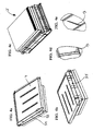
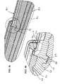
- Fig. 1a and 1c shows a roof tile 1 and a tongue and groove joint 8 according to the prior art, which has an outer skin 4 and a support body (here insulating body 5). In the insulating body 5 itself while a longitudinal side groove 81 and the broad side groove 27 are formed. In this prior art, adjacent roof tiles 1 and 2 are connected directly via their insulating body 5 and the corresponding tongue and groove joints.
- the disadvantage of the shown relatively thick Schaumbuchstoffisolier emotionss lies in the relatively difficult production of a single so thick foamed part. Due to the chemical reactions in thick insulating bodies (about 20 cm), the resulting reaction heat is very difficult to dissipate, since the mass is very large relative to the heat-dissipating surface.
- the insulating body 5 has at least a first 51 and second 52 insulating layer, wherein preferably the first insulating layer 51 is glued or foamed to the outer skin 4.
- the second insulating layer 52 may already prefabricated (for example made of polystyrene) or prefoamed. This layer 52 already has the final shape.
- two further intermediate layers 53 and two other layers 54 are attached to the side of the insulating layer 52 facing away from the outer skin, whereby these can serve for example for sound insulation, insulation or stability.
- the wide-side grooves 27 and springs 28 are generally formed.
- the individual layers can be made, for example, from polystyrene, PU, other insulating material, flexible foam, Mineralvllesplatten or the like.
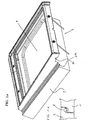
- Fig. 2 shows a view of this roof tile 1, wherein the outer skin 4 has a trough-shaped region for receiving a solar element 20, not shown here, wherein the connecting pieces 22 are already shown. Important are the longitudinal surface 25 of the insulating 5, the already formed recesses 7, which serve the later guidance of the mounting screws 6 when attaching the tile 1.
- the broad side of the tile 1 is denoted by 24.
- At 29 is in this Fig. 2 an exemption for the water flow from the broadside groove 27 in an underlying rail-shaped component 3 indicated.
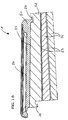
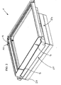
- Fig. 3a shows a view of the tile 1, wherein the solar element 20 is shown with fluid lines.
- Fig. 3b the entire insulating body 5 and insulating layer 52 is shown from below, with the nub structure 55 can be seen thereon.
- this nub structure 55 of the roof tile 1 is located on a shuttering 71.
- a third water-bearing plane 93 is formed as a drainage between the shuttering 71 (roof support structure 70) and the roof tiles 1.
- this nub structure 55 also forms a sound insulation.
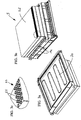
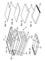
- FIG. 4a to 4e again details of the roof tile 1 according to the invention are shown, in particular, the recesses 7 are shown as a fastening screw guide when mounting the roof tiles 1, 2 in detail.
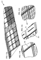
- the Fig. 5a to 5f show the individual layers of a particularly preferred embodiment of the tile described herein 1. This has seen from top to bottom an outer skin 4, a first insulating layer 51, a second insulating layer 52 with guide knobs, two intermediate layers 53 and two further layers 54.
- the insulating layer 52 with the underlying intermediate layers 54 and further layers 53 may be designed as a separate component, so that the lower parts 52, 53, 54 can be mounted independently of the upper part 51 with outer skin 4 on the roof.
- the intermediate plane forming here can form the second aquifer 92.
- 52 guide studs 57 are provided with corresponding, not shown counterparts on the underside of the insulating layer 51 on the insulating layer.
- Fig. 6a shows the insulating layer 52, which has the Breitrawnut 27 in the rear broad side region 24. This forms a second aquifer 92 (the outer skin 4 forms the first aquifer 91).
- this insulating layer 52 is slightly roof-shaped, which is due to the apex line 58 and the two thereof slightly sloping to the longitudinal side 25 surfaces visible.
- Fig. 6b shows a plan view of the insulating layer 52 including guide studs 57 and vertex line 58th
- Fig. 6c shows the entire insulating body 5 from below, along which the two longitudinal sides 25, the latching steps 14 and retaining bevels 13 are formed, which can engage in a slip-proof manner at later or later shown rail-shaped components 3 and their holding steps 9.
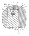
- Fig. 7a shows a cross section through the roof structure 50, wherein four juxtaposed tiles 1.2 are shown.
- these roof tiles 1,2 each have an outer skin 4 and disposed above a solar element 20.
- the roof tiles 1, 2 respectively engage via springs 82, 83 in a groove 81 of a rail-shaped component 3. How to do it in Fig. 7c it can be seen, engage these springs 82, 83, leaving a drainage channel 10 in the preformed groove 81 a.
- the fastening screw 6 is inserted exactly in the region of the guide recess 7 between the tile 1.2 and holds or fixed over the screw head 61 and the cap 62 (washer, washer) both tiles 1.2 on the rail-shaped component 3 fixed.
- a frictional connection is produced by the screw head 61 via the cap 62 on the outer skin 4 and on the insulating body 5.
- the tiles 1.2 themselves have no hole and are not directly connected to the roof support structure 70, whereby no thermal bridge is given by the attachment. Rather, how are out Fig. 7d can be seen, the rail-shaped components 3 separately via retaining means 31 (for example, angle) and fasteners 36 (screws, for example) attached to the casing 71.
- the holding means 31 are preferably provided individually over the length of the rail-shaped component 3.
- the attachment and entrance area of the two roof tiles 1 and 2 can, as in Fig. 7b shown to be additionally protected by a deferred cover rail 63.
- the detail 7d of the rail-shaped member 3 via the attachment means 36 is also connected directly to the Dachsparre 72 or held in this.
- Fig. 8a shows the three water-bearing levels 91, 92 and 93.
- the top, first water-bearing plane 91 is thereby formed essentially by the outer skin 4. If, nevertheless, water on the longitudinal side 25 and the broad side 24 passes between the individual tiles 1.2, the wide side groove 27 is formed in the insulating body 5 of the overlapped tile 1.2 on the broad side 24 as an additional second aquifer 92, wherein the engaging spring 28th of the overlapping roof tile 1,2 a Breittimeent camesssansanskanal 15 leaves free.
- Fig. 25 are to match the arrows on the long and long sides of the tiles 1.2, the flow direction of incoming water in the region of the second water-conducting parting plane 92 illustrated.
- the first water-separating plane 91 is formed by the correspondingly designated arrows on the outer skin 4 itself.
- Flg. 9 a and 22 a and 22 b show a roof 30 of a building 90, in which the roof support structure 70 of cross members 73, not shown rafters 72 and the shuttering 71 consists (the longitudinal orientation of the cross member 73 corresponds in this application, the extension of the roof width B and the longitudinal orientation of the Rafter 72 corresponds to the extent of the roof hey H).
- the rail-shaped components 3 are mounted in the roof height direction H.
- the individual roof tiles 1, 2 adjacent to each other via tongue and groove connections 8 are arranged engaging in the component 3. It can be seen in detail 9b that the roof tiles 1, 2 can themselves be made in two parts and attached to the roof 30.
- the insulating body 5 rests on the Schlenenförmlgen component 3 and the casing 71, after which the upper part of the tile (insulating layer 51 and outer skin 4) applied only when mounted on the roof on the lower part or be connected to this.
- This also facilitates the replacement of individual damaged upper or lower parts of the roof tiles.
- the non-slip positioning serve the guide knobs 57, which correspond with corresponding counterparts on the underside of the insulating layer 51, not shown. It can be seen in detail 9 c how the rail-shaped component 3 can be fastened to the casing 71 via the holding means 31 (in this case fastening straps).
- the rail-shaped components 3 themselves are the rafters 72, which are also attached or mounted, for example, via the fastening straps 31 directly to the cross members 73. Thereafter, the individual tiles 1, 2 can be applied to the rail-shaped components 3 on these rail-shaped components 3 in the same manner as that of a completely separate roof support structure 70. On the underside of the entire roof 30 then any cover plates can be mounted from the inside.
- the roof structure 50 can be seen, with different types of roof tiles 1, 2 forming the roof structure 50.
- solar elements 20 solar brick with fluid line 21 or photovoltaic brick
- Between the individual tiles 1.2 can serve an additional protective rail 64 of the seal and the better seal.
- the protective rail 64 and the cover rail 63 are formed as a single component in a constructive unit.
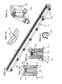
- Fig. 12a shows the Schlieren-shaped component 3 in its overall extent (for example, 4 meters), wherein in the front area ( Fig. 12c ) a connection piece 35 is shown.
- the connecting piece 35 can be designed as a flexible projection and connected by pure An Federationelung or by gluing with another rail-shaped component 3.
- Fig. 12b the holding stage 9 is shown with a corresponding recess 16, in which a matching tile 1.2 with its corresponding latching steps 14 and retaining bevels 13 can engage appropriately.
- the individual fastening straps 31 can be connected to one another via fastening hooks 33 which are formed in the rail-shaped component 3, which leads to a secure fastening form which does not form a thermal bridge.
- the individual fastening straps 31 can be attached to the roof 30 via fastening screws 36 (not illustrated here).
- the mounting tabs 31 can be better secured by bulges 34 in the rail-shaped component 3 or are more accessible during assembly.
- the preferred cross-sectional representation of the rail-shaped component 3 shown here is shown, the groove 81 being generally delimited by the two elevations 85 and 84. In the groove 81 itself, a recessed drainage channel 10 and a central plateau 86 are formed.
- the tongue-and-groove joint 8 is double in the sense that on the one hand, the rail-shaped member 3 has both a groove 81 and springs 84, 85 and on the other hand on the tile 1.2 both springs 82, 83 and grooves 87, 88 are arranged. It goes without saying, however, that it is sufficient for an embodiment according to the invention to provide only one of the two tongue and groove connections 8. In this context, be on the Fig. 7e referenced, in which it can be seen that here the roof tiles 1, 2 have no engaging springs.
- the grooves 87, 88 are formed here closed only on one side.
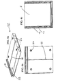
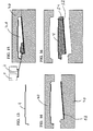
- a first possible manufacturing process is illustrated.
- the outer skin 4 for example, in a metal press, punched out and preformed.
- this outer skin 4 enters a mold 40 (see Fig. 14 ), wherein in the lower part of the mold 40, a second insulating layer 52 is already inserted.
- Fig. 15 It can be seen how by closing the mold halves 40, a cavity 41 is formed, in which a foamable plastic is filled, there reacts and cures.
- Two preferred components of this foam plastic are polyol P and isocyanate I.
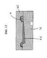
- FIG. 17 A second alternative or partially with the first combinable variant of the production goes from the Fig. 17 to 21 out. It will be in Fig. 17 first the first insulating layer 51 to the skin 4 in the form 40 angeschaumt. Subsequently, as in FIGS. 18 and 19 Prefabricated insulating layers 52 and 54 inserted into the open mold 40. After closing the mold 40 as in Fig. 20 remain two cavities 41, in which reactive foam plastic is filled. After curing and opening of the mold 40 results in an entire roof tile 1 consisting of outer skin 4 and insulator 5, said insulator 5 consists of the two insulating layers 51 and 52, the intermediate layers 53 and the further layer 54.
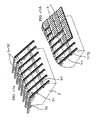
- Fig. 24a is the previously known, disadvantageous arrangement of roof tiles 1.2 shown. If, for example, the one in this Fig. 24a With 2 designated roof tiles to be replaced, all roof tile rows arranged above must be removed one after another to get to this a roof tile 2. In contrast, according to Fig. 24b now the access to the tile designated 2 already by removing, in the roof height direction H arranged above him further tiles possible,
- the rail-shaped components 3 themselves are preferably foamed from foamed plastic and preferably themselves form a further insulating layer of the entire roof structure 50. Through the drainage channel 10 in the rail-shaped component 3, a completely independent second water separation plane 92 is achieved. By attaching two roof tiles 1, 2 to a rail-shaped component 3 without forming a borehole in the roof tiles 1, 2 an uncomplicated, simple and very handy fixing and mounting of the entire roof structure 50 is achieved.
Landscapes
- Engineering & Computer Science (AREA)
- Architecture (AREA)
- Civil Engineering (AREA)
- Structural Engineering (AREA)
- Sustainable Development (AREA)
- Life Sciences & Earth Sciences (AREA)
- Physics & Mathematics (AREA)
- Sustainable Energy (AREA)
- Thermal Sciences (AREA)
- Chemical & Material Sciences (AREA)
- Combustion & Propulsion (AREA)
- Mechanical Engineering (AREA)
- General Engineering & Computer Science (AREA)
- Roof Covering Using Slabs Or Stiff Sheets (AREA)
- Fittings On The Vehicle Exterior For Carrying Loads, And Devices For Holding Or Mounting Articles (AREA)
Applications Claiming Priority (1)
| Application Number | Priority Date | Filing Date | Title |
|---|---|---|---|
| AT0198609A AT508902B1 (de) | 2009-12-15 | 2009-12-15 | Dachziegel mit trägerkörper aus wenigstens zwei schichten |
Publications (2)
| Publication Number | Publication Date |
|---|---|
| EP2336448A2 true EP2336448A2 (fr) | 2011-06-22 |
| EP2336448A3 EP2336448A3 (fr) | 2016-03-02 |
Family
ID=43517988
Family Applications (1)
| Application Number | Title | Priority Date | Filing Date |
|---|---|---|---|
| EP10015567.0A Withdrawn EP2336448A3 (fr) | 2009-12-15 | 2010-12-13 | Tuile de toit dotée d'un corps de support constitué d'au moins deux couches |
Country Status (2)
| Country | Link |
|---|---|
| EP (1) | EP2336448A3 (fr) |
| AT (1) | AT508902B1 (fr) |
Cited By (3)
| Publication number | Priority date | Publication date | Assignee | Title |
|---|---|---|---|---|
| US9151517B2 (en) | 2009-12-17 | 2015-10-06 | Designergy Sa | Substantially two-dimensional construction element |
| EP4257889A2 (fr) | 2022-04-08 | 2023-10-11 | Universität Stuttgart | Éléments de construction multifonctionnels de surface extérieure, leur fabrication et leur utilisation |
| EP4489296A2 (fr) | 2023-07-05 | 2025-01-08 | Universität Stuttgart | Éléments de construction multifonctionnels de surface extérieure, leur fabrication et leur utilisation |
Families Citing this family (4)
| Publication number | Priority date | Publication date | Assignee | Title |
|---|---|---|---|---|
| NL2012801B1 (nl) * | 2014-05-12 | 2016-02-24 | Stafier Holland B V | Dakpaneel en dak voorzien van een dergelijk dakpaneel. |
| CN109653447B (zh) * | 2017-10-11 | 2024-01-09 | 北京仁创科技集团有限公司 | 一种具有导水结构的砂塑瓦片 |
| CN112681725B (zh) * | 2020-12-22 | 2022-03-22 | 中铁建工集团山东有限公司 | 一种车库顶板密肋楼盖可周转模壳结构 |
| CN114809458B (zh) * | 2022-05-16 | 2023-07-21 | 车洪飞 | 一种钢结构厂房用屋面结构 |
Citations (4)
| Publication number | Priority date | Publication date | Assignee | Title |
|---|---|---|---|---|
| US2400357A (en) | 1943-10-08 | 1946-05-14 | Celotex Corp | Unit for roofs and walls |
| NL1025787C2 (nl) | 2004-03-22 | 2005-09-26 | Jansen Betonwaren B V | Meerlaags bedekkingssysteem. |
| JP2007009655A (ja) | 2005-07-04 | 2007-01-18 | Panahome Corp | 断熱瓦とその製造方法および屋根構造 |
| AT506953B1 (de) | 2008-07-29 | 2010-01-15 | Deutsch Wolfgang | Dachziegel |
Family Cites Families (5)
| Publication number | Priority date | Publication date | Assignee | Title |
|---|---|---|---|---|
| DE29500418U1 (de) * | 1995-01-12 | 1995-04-27 | Engels, Adolf Walter, 42929 Wermelskirchen | Schindel |
| JP3263328B2 (ja) * | 1996-12-25 | 2002-03-04 | 株式会社クボタ | 屋根瓦 |
| JP2001115602A (ja) * | 1999-10-20 | 2001-04-24 | Hitachi Ltd | 断熱材付屋根瓦 |
| ITMO20060100A1 (it) * | 2006-03-24 | 2007-09-25 | Isolant Di Grimaldi Ugo | Manufatto per la copertura di tetti o simili |
| DE202006012708U1 (de) * | 2006-08-15 | 2006-11-09 | Fleck, Oskar | Dacheindeckung mit einer ebenen sowie unterlüfteten Auflagerfläche |
-
2009
- 2009-12-15 AT AT0198609A patent/AT508902B1/de not_active IP Right Cessation
-
2010
- 2010-12-13 EP EP10015567.0A patent/EP2336448A3/fr not_active Withdrawn
Patent Citations (4)
| Publication number | Priority date | Publication date | Assignee | Title |
|---|---|---|---|---|
| US2400357A (en) | 1943-10-08 | 1946-05-14 | Celotex Corp | Unit for roofs and walls |
| NL1025787C2 (nl) | 2004-03-22 | 2005-09-26 | Jansen Betonwaren B V | Meerlaags bedekkingssysteem. |
| JP2007009655A (ja) | 2005-07-04 | 2007-01-18 | Panahome Corp | 断熱瓦とその製造方法および屋根構造 |
| AT506953B1 (de) | 2008-07-29 | 2010-01-15 | Deutsch Wolfgang | Dachziegel |
Cited By (3)
| Publication number | Priority date | Publication date | Assignee | Title |
|---|---|---|---|---|
| US9151517B2 (en) | 2009-12-17 | 2015-10-06 | Designergy Sa | Substantially two-dimensional construction element |
| EP4257889A2 (fr) | 2022-04-08 | 2023-10-11 | Universität Stuttgart | Éléments de construction multifonctionnels de surface extérieure, leur fabrication et leur utilisation |
| EP4489296A2 (fr) | 2023-07-05 | 2025-01-08 | Universität Stuttgart | Éléments de construction multifonctionnels de surface extérieure, leur fabrication et leur utilisation |
Also Published As
| Publication number | Publication date |
|---|---|
| AT508902A4 (de) | 2011-05-15 |
| EP2336448A3 (fr) | 2016-03-02 |
| AT508902B1 (de) | 2011-05-15 |
Similar Documents
| Publication | Publication Date | Title |
|---|---|---|
| DE69433730T2 (de) | Befestigung einer Wandverkleidung | |
| AT508902B1 (de) | Dachziegel mit trägerkörper aus wenigstens zwei schichten | |
| EP2925938B1 (fr) | Élément de revêtement pour un bâtiment | |
| EP1471189A3 (fr) | Bâtiment | |
| CH711305B1 (de) | Fussbodenelement. | |
| DE102006004626A1 (de) | Bauelement | |
| DE60023159T2 (de) | Hohlplatte zur herstellung von einem bodenfeld in welches leitungen eingebaut werden können und verfahren zum herstellen eines bodenfelds mit leitungen | |
| DE202010001675U1 (de) | Bodendämmplattensystem | |
| EP2149646A2 (fr) | Tuile | |
| DE102008048541A1 (de) | Schicht-Verbundelement und Verfahren zu dessen Herstellung | |
| EP2149647A2 (fr) | Tuile | |
| DE10230557C1 (de) | Unterbau für eine Duschtasse | |
| DE102016104330B4 (de) | Fassadenverkleidungs-Verbundelement, Fassadenverkleidung und Verfahren zu deren Herstellung | |
| AT508903B1 (de) | Dachverband mit nut-feder-verbindung zwischen dachziegeln und schienenförmigem bauteil | |
| EP1496171A2 (fr) | Elément de paroi pour le revêtement des façades ou similaire | |
| DE102015003338A1 (de) | Holz-Beton-Verbundkonstruktion und Verfahren zu deren Herstellung | |
| DE10124756B4 (de) | Wandsystem | |
| DE4436808A1 (de) | Verbindungselement | |
| DE3308469A1 (de) | Aus hartschaumstoff, vorzugsweise aus expandiertem polystyrol bestehende isolierplatte | |
| DE102011054037B4 (de) | Formelement aus thermischem Isolationsmaterial mit wenigstens einer integrierten Installationsdose für elektrische bzw. elektrotechnische Geräte und Verfahren zu dessen Herstellung | |
| DE69914386T2 (de) | Wärmeisolationspaneel zum Aufbringen auf Wandoberflächen, die insbesondere schnellen Temperaturschwankungen ausgesetzt sind | |
| DE102005031395B4 (de) | Kunststoffbauteil und Verfahren zum Befestigen eines Anbauteils an einem Kunststoffbauteil | |
| DE202012006046U1 (de) | Wärmedämmplatte für Gebäudefassaden | |
| DE202007016735U1 (de) | Aufkeilrahmen zur Montage eines Dachfensters in einem Gebäudedach | |
| DE202009010591U1 (de) | Thermisch wirksames Fassadenelement für Gebäudewände sowie System zur thermischen Isolierung einer Gebäudewand |
Legal Events
| Date | Code | Title | Description |
|---|---|---|---|
| PUAI | Public reference made under article 153(3) epc to a published international application that has entered the european phase |
Free format text: ORIGINAL CODE: 0009012 |
|
| AK | Designated contracting states |
Kind code of ref document: A2 Designated state(s): AL AT BE BG CH CY CZ DE DK EE ES FI FR GB GR HR HU IE IS IT LI LT LU LV MC MK MT NL NO PL PT RO RS SE SI SK SM TR |
|
| AX | Request for extension of the european patent |
Extension state: BA ME |
|
| RAP1 | Party data changed (applicant data changed or rights of an application transferred) |
Owner name: FRIEDRICH DEUTSCH METALLWERK GESELLSCHAFT M.B.H. |
|
| RIC1 | Information provided on ipc code assigned before grant |
Ipc: F24J 2/04 20060101ALI20151028BHEP Ipc: E04D 1/28 20060101AFI20151028BHEP Ipc: F24J 2/52 20060101ALI20151028BHEP |
|
| PUAL | Search report despatched |
Free format text: ORIGINAL CODE: 0009013 |
|
| AK | Designated contracting states |
Kind code of ref document: A3 Designated state(s): AL AT BE BG CH CY CZ DE DK EE ES FI FR GB GR HR HU IE IS IT LI LT LU LV MC MK MT NL NO PL PT RO RS SE SI SK SM TR |
|
| AX | Request for extension of the european patent |
Extension state: BA ME |
|
| STAA | Information on the status of an ep patent application or granted ep patent |
Free format text: STATUS: THE APPLICATION IS DEEMED TO BE WITHDRAWN |
|
| 18D | Application deemed to be withdrawn |
Effective date: 20160701 |