EP2336635A1 - Caisson de refroidissement destiné au refroidissement de gaz d'échappement, notamment de gaz d'échappement contenant de la poussière - Google Patents
Caisson de refroidissement destiné au refroidissement de gaz d'échappement, notamment de gaz d'échappement contenant de la poussière Download PDFInfo
- Publication number
- EP2336635A1 EP2336635A1 EP09015761A EP09015761A EP2336635A1 EP 2336635 A1 EP2336635 A1 EP 2336635A1 EP 09015761 A EP09015761 A EP 09015761A EP 09015761 A EP09015761 A EP 09015761A EP 2336635 A1 EP2336635 A1 EP 2336635A1
- Authority
- EP
- European Patent Office
- Prior art keywords
- boiler
- waste heat
- tie rod
- heat boiler
- cooling medium
- Prior art date
- Legal status (The legal status is an assumption and is not a legal conclusion. Google has not performed a legal analysis and makes no representation as to the accuracy of the status listed.)
- Granted
Links
- 238000001816 cooling Methods 0.000 title claims abstract description 51
- 239000002918 waste heat Substances 0.000 title claims description 49
- 239000000428 dust Substances 0.000 title claims description 10
- 239000002912 waste gas Substances 0.000 title description 3
- 239000002826 coolant Substances 0.000 claims abstract description 46
- 239000007789 gas Substances 0.000 claims description 24
- 238000007789 sealing Methods 0.000 claims description 17
- 230000008602 contraction Effects 0.000 claims description 6
- 239000012530 fluid Substances 0.000 claims 1
- 238000009835 boiling Methods 0.000 abstract description 3
- XLYOFNOQVPJJNP-UHFFFAOYSA-N water Substances O XLYOFNOQVPJJNP-UHFFFAOYSA-N 0.000 abstract description 3
- 229910000831 Steel Inorganic materials 0.000 description 12
- 239000010959 steel Substances 0.000 description 12
- 239000002184 metal Substances 0.000 description 4
- 238000010276 construction Methods 0.000 description 3
- 230000007935 neutral effect Effects 0.000 description 2
- 230000000149 penetrating effect Effects 0.000 description 2
- 238000000926 separation method Methods 0.000 description 2
- 238000010521 absorption reaction Methods 0.000 description 1
- 238000007599 discharging Methods 0.000 description 1
- 239000004744 fabric Substances 0.000 description 1
- 239000000463 material Substances 0.000 description 1
- 238000011084 recovery Methods 0.000 description 1
- 230000000284 resting effect Effects 0.000 description 1
- 230000006641 stabilisation Effects 0.000 description 1
- 238000011105 stabilization Methods 0.000 description 1
- 238000010408 sweeping Methods 0.000 description 1
- 238000003466 welding Methods 0.000 description 1
Images


Classifications
-
- F—MECHANICAL ENGINEERING; LIGHTING; HEATING; WEAPONS; BLASTING
- F22—STEAM GENERATION
- F22B—METHODS OF STEAM GENERATION; STEAM BOILERS
- F22B1/00—Methods of steam generation characterised by form of heating method
- F22B1/02—Methods of steam generation characterised by form of heating method by exploitation of the heat content of hot heat carriers
- F22B1/18—Methods of steam generation characterised by form of heating method by exploitation of the heat content of hot heat carriers the heat carrier being a hot gas, e.g. waste gas such as exhaust gas of internal-combustion engines
-
- F—MECHANICAL ENGINEERING; LIGHTING; HEATING; WEAPONS; BLASTING
- F22—STEAM GENERATION
- F22B—METHODS OF STEAM GENERATION; STEAM BOILERS
- F22B37/00—Component parts or details of steam boilers
- F22B37/02—Component parts or details of steam boilers applicable to more than one kind or type of steam boiler
- F22B37/10—Water tubes; Accessories therefor
- F22B37/20—Supporting arrangements, e.g. for securing water-tube sets
- F22B37/201—Suspension and securing arrangements for walls built-up from tubes
-
- F—MECHANICAL ENGINEERING; LIGHTING; HEATING; WEAPONS; BLASTING
- F22—STEAM GENERATION
- F22B—METHODS OF STEAM GENERATION; STEAM BOILERS
- F22B37/00—Component parts or details of steam boilers
- F22B37/02—Component parts or details of steam boilers applicable to more than one kind or type of steam boiler
- F22B37/10—Water tubes; Accessories therefor
- F22B37/20—Supporting arrangements, e.g. for securing water-tube sets
- F22B37/208—Backstay arrangements
Definitions
- the invention relates to a waste heat boiler for cooling exhaust gases, in particular of dust-containing exhaust gases, the boiler walls of the boiler having cooling pipe sections, which are flowed through by a cooling medium with a temperature T 1 .
- the exhaust gas flowing through the boiler is thus cooled by means of the cooling pipe sections through which the cooling medium flows.
- the cooling tube sections are usually components of a plurality of cooling tubes that run along the boiler walls. It is within the scope of the invention that these cooling pipes form the inner wall of the boiler.
- Waste heat boilers of the type described above are known in practice in various embodiments. In operation, they are under a gas-side overpressure, so that deformations or buckling of the boiler walls would result if no suitable countermeasures are initiated. Under unfavorable conditions also gas-side negative pressures occur, which are to be considered in the boiler design. The said pressures can not be absorbed in practice by the walls of the waste heat boiler alone. Therefore, the boiler walls are supported by bandages resting against the walls of the boiler. These bandages are usually rolled steel profiles whose size is determined by factors such as gas pressure, the distance between the profiles and the size of the surfaces to be cooled.
- the invention the technical problem of providing a waste heat boiler of the type mentioned, in which in a simple, effective and reliable manner deformations of the boiler walls can be reduced.
- the invention teaches a waste heat boiler for cooling exhaust gases, in particular dust-containing exhaust gases, wherein the boiler walls cooling tubes or cooling pipe sections, which are traversed by a cooling medium with a temperature T 1 ,
- opposing boiler walls of the boiler are interconnected by at least one tubular tie rod and wherein the tubular tie rod is also traversed by a cooling medium having a temperature T 1 .
- the arranged on the boiler walls of the waste heat boiler cooling tube sections are expediently components of a plurality of cooling tubes.
- the cooling medium is fed to the cooling pipe sections or cooling pipes via at least one feed line.
- About at least one return line, the heated in the waste heat boiler cooling medium is discharged again.
- Adjacent cooling pipe sections are preferably connected to one another via webs.
- the bulging of the walls of the boiler walls is avoided by means of at least one tubular tie rod.
- a tubular tie rod expediently consists of metal, in particular of steel. It is recommended that a plurality or a plurality of tubular tie rods are used to stabilize a boiler.
- the at least one tie rod or the tie rods is / are traversed by a cooling medium, which also has the temperature T 1 .
- the temperature T 1 of the cooling medium for the cooling tubes or cooling tube sections thus corresponds to the temperature T 1 or substantially the temperature T 1 of the cooling medium for the at least one tubular tie rod.
- the fact that the temperatures essentially correspond, in particular, means that the temperature difference is not greater than 10 ° C., preferably not greater than 5 ° C.
- the cooling medium for the cooling tubes or cooling tube sections and / or the cooling medium for the at least one tubular tie rod is expediently boiling water.
- cooling pipe sections run parallel to each other on the boiler walls. It is further within the scope of the invention that at least a part or the majority of the cooling tube sections are transverse to the flow direction of the exhaust gas or transversely to the Longitudinal direction of the boiler is arranged. Conveniently, adjacent cooling pipe sections are interconnected by webs, which are formed continuously in the cooling pipe section longitudinal direction. According to a preferred embodiment, the boiler wall is thus formed by the cooling tubes or by the cooling tube sections and the webs connecting them.
- the waste heat boiler is a horizontal waste heat boiler whose longitudinal axis is arranged horizontally or substantially horizontally and in the longitudinal direction through which the exhaust gas flows horizontally or substantially horizontally.
- the waste heat boiler is, in particular, a waste heat boiler for cooling dusty waste gases.
- the boiler then has a dust separator in its lower region. In a horizontal waste heat boiler, the dust separator extends in the longitudinal direction of the waste heat boiler.
- a plurality of tie rods is distributed over the height and / or over the length of the boiler.
- a plurality of tie rods fluidly connected in series one behind the other and these tie rods are successively flowed through by the cooling medium.
- a highly recommended embodiment of the invention is characterized in that the cooling medium for the cooling pipe sections is used as the cooling medium for the tie rod (s). Thereafter, therefore, no separate cooling medium is used for cooling the tie rods, but it is as it were a partial flow of the cooling medium used for the cooling pipe sections for cooling the tie rods.
- a tie rod to the flow line of the Cooling medium connected to the cooling pipe sections and the cooling medium is introduced after flowing through the tie rod or after flowing through a plurality of fluidically connected in series tie rods in the return line of the cooling medium for the cooling pipe sections. It is within the scope of the invention that, when the tie rods are connected in series in series, two tie rods connected in series are flowed through by the cooling medium in the opposite direction.
- a tie rod connected to a supply line is flowed through by the cooling medium in a first direction and the second tie rod connected to the first tie rod is then flowed through by the flow medium in a second direction opposite to the first and the third tie rod connected to the second tie rod becomes then flows again in the first direction of the cooling medium, etc. ..
- a plurality of tie rods distributed over the height of the boiler are arranged one above the other and this plurality of tie rods is arranged in particular in a vertical plane or substantially in a vertical plane.
- a plurality of vertical planes or of substantially vertical planes, each with a plurality of tie rods arranged one above the other are arranged one behind the other in the longitudinal direction of the vessel.
- two vertical planes or two essentially vertical planes are advantageously each connected in series with flow anchors arranged one above the other in each case and flow through the cooling medium in succession. It is within the scope of the invention that two successively flowed tie rods are connected to each other via a running along the outside of the boiler tubular connecting portion.
- the exhaust gas in the boiler is under a pressure of 50 to 200 mbar, in particular under a pressure of 70 to 190 mbar.
- EmpfohleneIER are arranged on the outer sides of the boiler or the boiler walls bandage elements on which the boiler walls can be supported.
- the boiler walls are fixed to the bandage elements, so that when movements or strains of the boiler walls and the bandage elements are moved or mitgedehnt.
- the bandage elements are steel profiles and in particular rolled steel profiles. It is recommended that the bandage elements are oriented horizontally and / or vertically.
- horizontally oriented bandage elements are provided which extend parallel to the longitudinal axis of the boiler and provided vertically oriented bandage elements which extend perpendicular to the longitudinal axis of the boiler.
- a tubular tie rod engages through the two opposing boiler walls connected by it and thus projects in each case on the outside of the two boiler walls.
- at least one on the outside projecting tie rod portion of a tie rod is connected via a running along the outside of the boiler tubular connecting portion with another tie rod or with a projecting on the outside of the boiler tie rod portion of this further tie rod.
- a tie rod has a section arranged in the boiler, which extends from the one boiler inner wall to the opposite boiler inner wall and which has on the outside of each of the two opposite boiler walls each having an outwardly projecting tie rod section.
- a is a Boiler wall penetrating tie rod not fixed to the boiler wall. The boiler wall can then move or stretch relative to the tie rod.
- a particularly preferred embodiment of the invention is characterized in that at least one support flange is fixed to a tie rod penetrating a boiler wall or to a tie rod section projecting from the outside of the boiler wall, to which a bandage element arranged on this outer side can be supported. Conveniently, it is a metal support flange which is welded to the metallic tie rod section. It is within the scope of the invention that at least one support flange is fixed to the each of the opposite boiler walls outwardly projecting tie rod sections of the tie rod.
- a first Abstweilflansch is fixed to a tie rod or on a projecting from the outside of the boiler wall Werankerabrough the tie rod on which the bandage can be supported in an expansion of the boiler wall due to overpressure in the boiler and at this tie rod or on said projecting tie rod portion a second Abstweilflansch is fixed to which the bandage can be supported in a contraction of the boiler wall due to negative pressure in the boiler.
- That a support flange is fixed to a tie rod or Werankerabêt means within the scope of the invention in particular that the Abstützflansch is firmly connected to the tie rod or Werankerabsacrificing and can perform any relative movement to the tie rod or Werankerabrough.
- such a fixed support flange is welded to the tie rod or to the tie rod portion.
- the two Abstweilflansche a projecting tie rod portion as mutually parallel support plates educated. It is within the scope of the invention that the two aforementioned Abstweilflansche are fixed on each side of the boiler at the there respectively outwardly projecting Glasankerabroughen the tie rod.
- a contact plate is fixed to a bandage element to be supported on the at least one support flange and the bandage element can be supported on the at least one support flange via this contact plate.
- the contact plate is welded as a metallic contact plate to the metallic bandage element.
- Empfohleneworth the contact plate protrudes into a space between the two preferably fixed to an outwardly projecting tie rod section Abstützflanschen.
- this contact plate is arranged in the same neutral state at a distance from each of the two Abstützflansche a Ceiankerabiteses.
- said tie rod portion passes through the contact plate so that the contact plate is movable relative to the tie rod portion.
- a boiler wall by a sweeping tie rod or outwardly projecting from the boiler wall Switzerland wall by a sweeping tie rod or outwardly projecting from the boiler wall
- a sealing jacket which sealing jacket surrounds the Buchankerabrough gas-tight.
- a tie rod preferably passes through a boiler wall without fixing. Through the corresponding opening of the boiler wall gas can escape to the outside. So that this gas does not reach the environment, the preferred sealing jacket is arranged around the outwardly projecting tie rod section.
- the sealing jacket is fixed gas-tight on the one hand to the boiler wall and on the other hand fixed gas-tight on a support flange of Switzerlandankerabroughes.
- the sealing jacket preferably consists essentially of metal and in particular substantially of steel.
- the sealing jacket is welded to the boiler wall on the one hand and on a support flange on the other hand gas-tight.
- a sealing jacket has a compensator which permits expansion and / or contractions of the vessel wall relative to the supporting flange.
- the invention is based first of the finding that with the waste heat boiler according to the invention simple, effective and reliable due to gas pressure or by gas pressure-induced bulges or deformations of the boiler walls can be significantly reduced.
- the invention is further based on the finding that it is expedient if the tie rods used according to the invention with the cooling medium to the same Temperature are cooled, as the boiler walls forming cooling pipe sections. In this way differential expansion or deformation of the boiler walls can be effectively reduced.
- the tie rods used according to the invention can be subjected to high loads on the train, so that the invention can be realized with an advantageously low use of material.
- the number of tie rods to be used depends solely on the size of the boiler wall surface to be demounted.
- the measures according to the invention are particularly suitable for large heat recovery boilers and / or for waste heat boilers with dust separation devices in which revolving bandage systems are not possible.
- a complex support of the waste heat boiler to a complex outer steel construction in an advantageous manner is no longer required.
- the force balance for reducing the deformations on the waste heat boiler takes place within the bandage system of the waste heat boiler.
- the invention is furthermore based on the finding that the cooling medium which is present anyway for the cooling of the boiler walls can also be used for cooling the tubular tie rods according to the invention. It should be emphasized that the success of the invention can be realized simply and with little effort and with cost-effective measures. This also contributes to the fact that the tie rods on the boiler walls need not be fixed or need not be welded.
- the figures show a waste heat boiler according to the invention for the cooling of dust-containing exhaust gases.
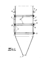
- Fig. 1 . 2 and 4 can be removed, it concerns in the waste heat boiler according to the invention to a preferred embodiment of a horizontal waste heat boiler, which is flowed through in the longitudinal direction or in the horizontal direction of the exhaust gas.
- This lying waste heat boiler has a funnel-shaped dust separation device 1, which is arranged in the lower part of the boiler.
- it may be a waste heat boiler with relatively large dimensions.
- horizontal bandages 3 and vertical bandages 4 are provided.
- the boiler walls 2 of the waste heat boiler have cooling tube sections 5 which are components of cooling tubes 6 through which a cooling medium flows at a temperature T 1 .
- the cooling pipe sections 5 are preferably connected to each other in the exemplary embodiment by webs 7.
- the Kesselthe 2 are thus formed essentially by the cooling pipes 6 and by the cooling pipe sections 5 and the webs 7.
- a feed line 8 is provided for supplying the cooling medium and for discharging the heated cooling medium, a return line 9.
- As the cooling medium boiling water is preferably used.
- opposite boiler walls 2 of the boiler are connected by tubular tie rods 10 together.
- the tubular tie rods 10 are also traversed by a cooling medium with the temperature T 1 .
- the cooling medium for the cooling pipe sections 5 is also used as a cooling medium for the tubular tie rods 10.
- the tie rods 10 and the tie rod aggregates explained below are also connected to the flow line 8 and to the return line 9 for the cooling medium.
- a plurality of tie rods 10 is arranged distributed over the height and over the length of the boiler.
- six tie rods 10 are distributed over the height of the boiler arranged in a vertical plane in the embodiment.
- These tie rods 10 of a vertical plane are fluidically connected in series and the tie rods 10 of a vertical plane are successively flowed through by the cooling medium.
- a plurality of vertical planes, each with six tie rods 10 arranged one above the other are arranged one behind the other in the longitudinal direction of the vessel.
- the vertical planes with the tie rods 10 arranged one above the other are arranged between cooling tube bundles 11, which protrude into the interior of the boiler for cooling the exhaust gas.
- two vertical planes each with six tie rods 10 arranged one above the other, are fluidically connected in series and are successively flowed through by the cooling medium.
- the lower tie rods 10 second such vertical planes are connected to each other via a running along the outside of the boiler tube section 12.
- the upper tie rod 10 of a first vertical plane is connected to the flow line 8
- the upper tie rod 10 of the second vertical plane connected to the first vertical plane is connected to the return line 9.
- two successively flowed tie rods 10 are connected to each other via a running along the outside of the boiler tubular connecting portion 13. Two successively flowed tie rods 10 are otherwise flowed through in the opposite direction of the cooling medium.
- the gas pressure in the waste heat boiler may be 50 to 200 mbar during operation of the boiler.
- 2 bandage elements 3, 4 are arranged for stabilization on the outer sides of the boiler walls, on which the boiler walls 2 are supported.
- horizontal, parallel to the longitudinal axis L of the boiler oriented bandage elements 3 are provided, and vertically oriented bandage elements 4.
- the vertical bandage elements 4 are arranged in the embodiment at the height of the cooling tube bundles 11.
- the bandage elements 3, 4 are in particular steel profiles and in the exemplary embodiment to double T-beam.
- tubular tie rods 10 in each case pass through the two opposite boiler walls 2 connected by them.
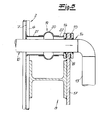
- the enlarged section to the Fig. 3 is removed that a cooling pipe section 5 was bent as it were to the side to make room for a to create the boiler wall 2 by cross tie rod 10.
- the tie rods 10 pass through the boiler wall 2 without fixing on the boiler wall 2.
- a tie rod 10 thus has a longer section arranged in the boiler, which extends from the one boiler wall 2 to the opposite boiler wall 2 and on both sides of the boiler to the outside of the boiler projecting Wegankerabismee 14th
- the contact plate 17 engages in a space between the two Abstweilflanschen 15, 16 and has a distance to both the outer Abstweilflansch 15 and the inner Abstweilflansch 16 in the same neutral state. Since the bandage elements 3, 4 are fixed to the boiler walls 2, complete the horizontal bandage elements 3 and thus also the contact plates fixed thereto 17 movements of the boiler walls 2 with. If the boiler walls 2 expand due to an overpressure in the boiler, and the horizontal bandage elements 3 are mitgedehnt and then can be fixed to a horizontal bandage element 3 contact plate 17 are supported on the outer support flange 15 of a tie rod portion 14.
- the tie rods 10 pass through the boiler walls 2 without fixing to the boiler walls 2, in particular without welding to the boiler walls 2. This allows movements or expansions of the boiler walls 2 relative to the tie rods 10. Through gaps or gaps between a boiler wall 2 and a tie rod 10 gas can escape from the boiler to the outside.
- a projecting from a boiler wall 2 Zaankerabchanging 14 for sealing a sealing jacket 19, which surrounds the projecting Werankerabites 14 gas-tight.
- the sealing jacket 19 is preferably and in the embodiment substantially of metal or steel.
- the sealing jacket 19 is fixed on the one hand to the associated boiler wall 2 gas-tight, in particular welded and on the other hand gas-tight fixed to the inner Abstützflansch 16, in particular welded. In this way, a functionally reliable seal is ensured at the points at which the tie rods 10 pass through the boiler walls 2.
- a compensator 20 is arranged.
- This compensator 20 may be a gas-tight compensator made of a fabric. This compensator 20 compensates for forces that occur during movements of the vessel wall 2 and the sealing jacket section 21 fixed thereto relative to the tie rod 10 and the sealing jacket section 22 connected thereto via the inner support flange 16.
Landscapes
- Engineering & Computer Science (AREA)
- Physics & Mathematics (AREA)
- Thermal Sciences (AREA)
- Mechanical Engineering (AREA)
- General Engineering & Computer Science (AREA)
- Chemical & Material Sciences (AREA)
- Combustion & Propulsion (AREA)
- Life Sciences & Earth Sciences (AREA)
- Sustainable Development (AREA)
- Sustainable Energy (AREA)
- Heat-Exchange Devices With Radiators And Conduit Assemblies (AREA)
Priority Applications (4)
| Application Number | Priority Date | Filing Date | Title |
|---|---|---|---|
| EP09015761.1A EP2336635B1 (fr) | 2009-12-19 | 2009-12-19 | Chaudière de récupération de chaleur destinée au refroidissement de gaz d'échappement, notamment de gaz d'échappement contenant de la poussière |
| MA33424A MA32445B1 (fr) | 2009-12-19 | 2010-12-13 | Chaudiere à chaleur perdue pour refroidissement de gaz d'échappement en particulier de gaz d'échappement contenant de la poussiere. |
| AU2010257257A AU2010257257B2 (en) | 2009-12-19 | 2010-12-16 | Waste-heat boiler for cooling waste gases, in particular particle-laden waste gases |
| US12/972,586 US8555822B2 (en) | 2009-12-19 | 2010-12-20 | Waste-heat boiler for partical-laden gases |
Applications Claiming Priority (1)
| Application Number | Priority Date | Filing Date | Title |
|---|---|---|---|
| EP09015761.1A EP2336635B1 (fr) | 2009-12-19 | 2009-12-19 | Chaudière de récupération de chaleur destinée au refroidissement de gaz d'échappement, notamment de gaz d'échappement contenant de la poussière |
Publications (2)
| Publication Number | Publication Date |
|---|---|
| EP2336635A1 true EP2336635A1 (fr) | 2011-06-22 |
| EP2336635B1 EP2336635B1 (fr) | 2014-07-30 |
Family
ID=43477977
Family Applications (1)
| Application Number | Title | Priority Date | Filing Date |
|---|---|---|---|
| EP09015761.1A Not-in-force EP2336635B1 (fr) | 2009-12-19 | 2009-12-19 | Chaudière de récupération de chaleur destinée au refroidissement de gaz d'échappement, notamment de gaz d'échappement contenant de la poussière |
Country Status (4)
| Country | Link |
|---|---|
| US (1) | US8555822B2 (fr) |
| EP (1) | EP2336635B1 (fr) |
| AU (1) | AU2010257257B2 (fr) |
| MA (1) | MA32445B1 (fr) |
Families Citing this family (1)
| Publication number | Priority date | Publication date | Assignee | Title |
|---|---|---|---|---|
| EP4653418A1 (fr) | 2024-05-22 | 2025-11-26 | Covestro Deutschland AG | Procédé de préparation d'isocyanate organique ayant une durabilité améliorée |
Citations (7)
| Publication number | Priority date | Publication date | Assignee | Title |
|---|---|---|---|---|
| GB1009034A (en) * | 1963-10-08 | 1965-11-03 | Vorkauf Heinrich | Steam boilers with fluid cooled supporting framework |
| GB1118881A (en) * | 1965-03-29 | 1968-07-03 | Duerrwerke Ag | Improvements relating to tubulous walls |
| FR2104331A5 (fr) * | 1970-08-14 | 1972-04-14 | Babcock Atlantique Sa | |
| JPH07269803A (ja) * | 1994-03-30 | 1995-10-20 | Mitsubishi Heavy Ind Ltd | 排ガスボイラ |
| JP2004092988A (ja) * | 2002-08-30 | 2004-03-25 | Babcock Hitachi Kk | 排熱回収ボイラ及びその据付方法 |
| US20070119388A1 (en) * | 2003-07-30 | 2007-05-31 | Babcock-Hitachi Kabushiki Kaisha | Heat exchanger tube panel module, and method of constructing exhaust heat recovery boiler using the same |
| EP2026000A1 (fr) * | 2007-08-10 | 2009-02-18 | Siemens Aktiengesellschaft | Générateur de vapeur |
Family Cites Families (4)
| Publication number | Priority date | Publication date | Assignee | Title |
|---|---|---|---|---|
| JPS6042843B2 (ja) * | 1979-07-30 | 1985-09-25 | 東洋エンジニアリング株式会社 | 廃熱ボイラ− |
| US4305909A (en) * | 1979-10-17 | 1981-12-15 | Peabody Process Systems, Inc. | Integrated flue gas processing system |
| US4364910A (en) * | 1980-03-13 | 1982-12-21 | Peabody Process Systems, Inc. | Integrated flue gas processing method |
| US5653282A (en) * | 1995-07-19 | 1997-08-05 | The M. W. Kellogg Company | Shell and tube heat exchanger with impingement distributor |
-
2009
- 2009-12-19 EP EP09015761.1A patent/EP2336635B1/fr not_active Not-in-force
-
2010
- 2010-12-13 MA MA33424A patent/MA32445B1/fr unknown
- 2010-12-16 AU AU2010257257A patent/AU2010257257B2/en not_active Ceased
- 2010-12-20 US US12/972,586 patent/US8555822B2/en not_active Expired - Fee Related
Patent Citations (7)
| Publication number | Priority date | Publication date | Assignee | Title |
|---|---|---|---|---|
| GB1009034A (en) * | 1963-10-08 | 1965-11-03 | Vorkauf Heinrich | Steam boilers with fluid cooled supporting framework |
| GB1118881A (en) * | 1965-03-29 | 1968-07-03 | Duerrwerke Ag | Improvements relating to tubulous walls |
| FR2104331A5 (fr) * | 1970-08-14 | 1972-04-14 | Babcock Atlantique Sa | |
| JPH07269803A (ja) * | 1994-03-30 | 1995-10-20 | Mitsubishi Heavy Ind Ltd | 排ガスボイラ |
| JP2004092988A (ja) * | 2002-08-30 | 2004-03-25 | Babcock Hitachi Kk | 排熱回収ボイラ及びその据付方法 |
| US20070119388A1 (en) * | 2003-07-30 | 2007-05-31 | Babcock-Hitachi Kabushiki Kaisha | Heat exchanger tube panel module, and method of constructing exhaust heat recovery boiler using the same |
| EP2026000A1 (fr) * | 2007-08-10 | 2009-02-18 | Siemens Aktiengesellschaft | Générateur de vapeur |
Also Published As
| Publication number | Publication date |
|---|---|
| AU2010257257A1 (en) | 2011-07-07 |
| EP2336635B1 (fr) | 2014-07-30 |
| US20110146595A1 (en) | 2011-06-23 |
| MA32445B1 (fr) | 2011-07-03 |
| US8555822B2 (en) | 2013-10-15 |
| AU2010257257B2 (en) | 2014-11-27 |
Similar Documents
| Publication | Publication Date | Title |
|---|---|---|
| DE3028563A1 (de) | Abhitzekessel | |
| DE2708696A1 (de) | Mehrschichtiger rohrboden fuer waermetauscher | |
| DE1601215B2 (de) | Plattenwaermetauscher insbesondere als spaltgaskuehler | |
| EP0171583B1 (fr) | Système tubulaire de réaction d'un four de craquage à tubes | |
| EP2336635B1 (fr) | Chaudière de récupération de chaleur destinée au refroidissement de gaz d'échappement, notamment de gaz d'échappement contenant de la poussière | |
| DE19631291C2 (de) | Isolationsverkleidung | |
| DE102020114303A1 (de) | Flansch, Flanschverbindung und Verfahren zum Betrieb einer Flanschverbindung | |
| DE1239319B (de) | Wassergekuehlte Aufhaengung von Dampferzeugern | |
| DE1029016B (de) | Kompensation mit Abdichtung fuer Roehrenwaermeaustauscher | |
| DE2809126C2 (de) | Spaltofen | |
| EP2857533B1 (fr) | Dispositif de production de métal, en particulier de cuivre | |
| DE3911257C2 (de) | Wärmetauscher | |
| EP0330666B1 (fr) | Reacteur a lit fluidise avec un logement moule en acier allie | |
| DE1551480B1 (de) | Doppelrohr waermetauscher fuer hohe druecke | |
| DE102015101356A1 (de) | Roststab mit Kühlmittel-Kanal | |
| DE3042557A1 (de) | Waermetauscher, insbesondere fuer sonnenkraftwerke | |
| DE3734523A1 (de) | Ladeluftkuehler | |
| DE1501621B2 (de) | In einem druckbehaelter angeordneter waermeuebertrager | |
| DE2906743C2 (fr) | ||
| EP0809081B1 (fr) | Echangeur de chaleur hybride à plaques | |
| DE2905593A1 (de) | Druckbehaelter fuer heisse medien | |
| DE2651470C2 (de) | Gehäuse für einen Elektroabscheider | |
| DE102008038663A1 (de) | Wärmetauscher mit einem Rohrbündel aus parallel zueinander verlaufenden, aus Kunststoff bestehenden Rohren | |
| DE1900538C3 (de) | Absperrschieber für große Leitungsdruchmesser | |
| DE102009053554A1 (de) | Wärmeübertrager |
Legal Events
| Date | Code | Title | Description |
|---|---|---|---|
| PUAI | Public reference made under article 153(3) epc to a published international application that has entered the european phase |
Free format text: ORIGINAL CODE: 0009012 |
|
| AK | Designated contracting states |
Kind code of ref document: A1 Designated state(s): AT BE BG CH CY CZ DE DK EE ES FI FR GB GR HR HU IE IS IT LI LT LU LV MC MK MT NL NO PL PT RO SE SI SK SM TR |
|
| AX | Request for extension of the european patent |
Extension state: AL BA RS |
|
| 17P | Request for examination filed |
Effective date: 20110920 |
|
| RIC1 | Information provided on ipc code assigned before grant |
Ipc: F22B 37/20 20060101ALI20131216BHEP Ipc: F22B 1/18 20060101AFI20131216BHEP |
|
| GRAP | Despatch of communication of intention to grant a patent |
Free format text: ORIGINAL CODE: EPIDOSNIGR1 |
|
| INTG | Intention to grant announced |
Effective date: 20140321 |
|
| GRAS | Grant fee paid |
Free format text: ORIGINAL CODE: EPIDOSNIGR3 |
|
| GRAA | (expected) grant |
Free format text: ORIGINAL CODE: 0009210 |
|
| AK | Designated contracting states |
Kind code of ref document: B1 Designated state(s): AT BE BG CH CY CZ DE DK EE ES FI FR GB GR HR HU IE IS IT LI LT LU LV MC MK MT NL NO PL PT RO SE SI SK SM TR |
|
| REG | Reference to a national code |
Ref country code: GB Ref legal event code: FG4D Free format text: NOT ENGLISH |
|
| REG | Reference to a national code |
Ref country code: CH Ref legal event code: EP |
|
| REG | Reference to a national code |
Ref country code: AT Ref legal event code: REF Ref document number: 680169 Country of ref document: AT Kind code of ref document: T Effective date: 20140815 |
|
| REG | Reference to a national code |
Ref country code: IE Ref legal event code: FG4D Free format text: LANGUAGE OF EP DOCUMENT: GERMAN |
|
| REG | Reference to a national code |
Ref country code: DE Ref legal event code: R096 Ref document number: 502009009713 Country of ref document: DE Effective date: 20140911 |
|
| REG | Reference to a national code |
Ref country code: NL Ref legal event code: VDEP Effective date: 20140730 |
|
| REG | Reference to a national code |
Ref country code: LT Ref legal event code: MG4D |
|
| REG | Reference to a national code |
Ref country code: EE Ref legal event code: FG4A Ref document number: E009954 Country of ref document: EE Effective date: 20141028 |
|
| PG25 | Lapsed in a contracting state [announced via postgrant information from national office to epo] |
Ref country code: ES Free format text: LAPSE BECAUSE OF FAILURE TO SUBMIT A TRANSLATION OF THE DESCRIPTION OR TO PAY THE FEE WITHIN THE PRESCRIBED TIME-LIMIT Effective date: 20140730 Ref country code: NO Free format text: LAPSE BECAUSE OF FAILURE TO SUBMIT A TRANSLATION OF THE DESCRIPTION OR TO PAY THE FEE WITHIN THE PRESCRIBED TIME-LIMIT Effective date: 20141030 Ref country code: LT Free format text: LAPSE BECAUSE OF FAILURE TO SUBMIT A TRANSLATION OF THE DESCRIPTION OR TO PAY THE FEE WITHIN THE PRESCRIBED TIME-LIMIT Effective date: 20140730 Ref country code: PT Free format text: LAPSE BECAUSE OF FAILURE TO SUBMIT A TRANSLATION OF THE DESCRIPTION OR TO PAY THE FEE WITHIN THE PRESCRIBED TIME-LIMIT Effective date: 20141202 Ref country code: FI Free format text: LAPSE BECAUSE OF FAILURE TO SUBMIT A TRANSLATION OF THE DESCRIPTION OR TO PAY THE FEE WITHIN THE PRESCRIBED TIME-LIMIT Effective date: 20140730 Ref country code: SE Free format text: LAPSE BECAUSE OF FAILURE TO SUBMIT A TRANSLATION OF THE DESCRIPTION OR TO PAY THE FEE WITHIN THE PRESCRIBED TIME-LIMIT Effective date: 20140730 Ref country code: GR Free format text: LAPSE BECAUSE OF FAILURE TO SUBMIT A TRANSLATION OF THE DESCRIPTION OR TO PAY THE FEE WITHIN THE PRESCRIBED TIME-LIMIT Effective date: 20141031 Ref country code: BG Free format text: LAPSE BECAUSE OF FAILURE TO SUBMIT A TRANSLATION OF THE DESCRIPTION OR TO PAY THE FEE WITHIN THE PRESCRIBED TIME-LIMIT Effective date: 20141030 |
|
| PG25 | Lapsed in a contracting state [announced via postgrant information from national office to epo] |
Ref country code: HR Free format text: LAPSE BECAUSE OF FAILURE TO SUBMIT A TRANSLATION OF THE DESCRIPTION OR TO PAY THE FEE WITHIN THE PRESCRIBED TIME-LIMIT Effective date: 20140730 Ref country code: PL Free format text: LAPSE BECAUSE OF FAILURE TO SUBMIT A TRANSLATION OF THE DESCRIPTION OR TO PAY THE FEE WITHIN THE PRESCRIBED TIME-LIMIT Effective date: 20140730 Ref country code: NL Free format text: LAPSE BECAUSE OF FAILURE TO SUBMIT A TRANSLATION OF THE DESCRIPTION OR TO PAY THE FEE WITHIN THE PRESCRIBED TIME-LIMIT Effective date: 20140730 Ref country code: IS Free format text: LAPSE BECAUSE OF FAILURE TO SUBMIT A TRANSLATION OF THE DESCRIPTION OR TO PAY THE FEE WITHIN THE PRESCRIBED TIME-LIMIT Effective date: 20141130 Ref country code: LV Free format text: LAPSE BECAUSE OF FAILURE TO SUBMIT A TRANSLATION OF THE DESCRIPTION OR TO PAY THE FEE WITHIN THE PRESCRIBED TIME-LIMIT Effective date: 20140730 Ref country code: CY Free format text: LAPSE BECAUSE OF FAILURE TO SUBMIT A TRANSLATION OF THE DESCRIPTION OR TO PAY THE FEE WITHIN THE PRESCRIBED TIME-LIMIT Effective date: 20140730 |
|
| PG25 | Lapsed in a contracting state [announced via postgrant information from national office to epo] |
Ref country code: DK Free format text: LAPSE BECAUSE OF FAILURE TO SUBMIT A TRANSLATION OF THE DESCRIPTION OR TO PAY THE FEE WITHIN THE PRESCRIBED TIME-LIMIT Effective date: 20140730 Ref country code: RO Free format text: LAPSE BECAUSE OF FAILURE TO SUBMIT A TRANSLATION OF THE DESCRIPTION OR TO PAY THE FEE WITHIN THE PRESCRIBED TIME-LIMIT Effective date: 20140730 Ref country code: IT Free format text: LAPSE BECAUSE OF FAILURE TO SUBMIT A TRANSLATION OF THE DESCRIPTION OR TO PAY THE FEE WITHIN THE PRESCRIBED TIME-LIMIT Effective date: 20140730 Ref country code: SK Free format text: LAPSE BECAUSE OF FAILURE TO SUBMIT A TRANSLATION OF THE DESCRIPTION OR TO PAY THE FEE WITHIN THE PRESCRIBED TIME-LIMIT Effective date: 20140730 Ref country code: CZ Free format text: LAPSE BECAUSE OF FAILURE TO SUBMIT A TRANSLATION OF THE DESCRIPTION OR TO PAY THE FEE WITHIN THE PRESCRIBED TIME-LIMIT Effective date: 20140730 |
|
| REG | Reference to a national code |
Ref country code: DE Ref legal event code: R097 Ref document number: 502009009713 Country of ref document: DE |
|
| PLBE | No opposition filed within time limit |
Free format text: ORIGINAL CODE: 0009261 |
|
| STAA | Information on the status of an ep patent application or granted ep patent |
Free format text: STATUS: NO OPPOSITION FILED WITHIN TIME LIMIT |
|
| PG25 | Lapsed in a contracting state [announced via postgrant information from national office to epo] |
Ref country code: BE Free format text: LAPSE BECAUSE OF NON-PAYMENT OF DUE FEES Effective date: 20141231 |
|
| 26N | No opposition filed |
Effective date: 20150504 |
|
| PG25 | Lapsed in a contracting state [announced via postgrant information from national office to epo] |
Ref country code: LU Free format text: LAPSE BECAUSE OF FAILURE TO SUBMIT A TRANSLATION OF THE DESCRIPTION OR TO PAY THE FEE WITHIN THE PRESCRIBED TIME-LIMIT Effective date: 20141219 |
|
| REG | Reference to a national code |
Ref country code: CH Ref legal event code: PL |
|
| GBPC | Gb: european patent ceased through non-payment of renewal fee |
Effective date: 20141219 |
|
| REG | Reference to a national code |
Ref country code: IE Ref legal event code: MM4A |
|
| REG | Reference to a national code |
Ref country code: FR Ref legal event code: ST Effective date: 20150831 |
|
| PG25 | Lapsed in a contracting state [announced via postgrant information from national office to epo] |
Ref country code: IE Free format text: LAPSE BECAUSE OF NON-PAYMENT OF DUE FEES Effective date: 20141219 Ref country code: GB Free format text: LAPSE BECAUSE OF NON-PAYMENT OF DUE FEES Effective date: 20141219 Ref country code: LI Free format text: LAPSE BECAUSE OF NON-PAYMENT OF DUE FEES Effective date: 20141231 Ref country code: CH Free format text: LAPSE BECAUSE OF NON-PAYMENT OF DUE FEES Effective date: 20141231 |
|
| PG25 | Lapsed in a contracting state [announced via postgrant information from national office to epo] |
Ref country code: FR Free format text: LAPSE BECAUSE OF NON-PAYMENT OF DUE FEES Effective date: 20141231 Ref country code: SI Free format text: LAPSE BECAUSE OF FAILURE TO SUBMIT A TRANSLATION OF THE DESCRIPTION OR TO PAY THE FEE WITHIN THE PRESCRIBED TIME-LIMIT Effective date: 20140730 |
|
| REG | Reference to a national code |
Ref country code: AT Ref legal event code: MM01 Ref document number: 680169 Country of ref document: AT Kind code of ref document: T Effective date: 20141219 |
|
| PG25 | Lapsed in a contracting state [announced via postgrant information from national office to epo] |
Ref country code: SM Free format text: LAPSE BECAUSE OF FAILURE TO SUBMIT A TRANSLATION OF THE DESCRIPTION OR TO PAY THE FEE WITHIN THE PRESCRIBED TIME-LIMIT Effective date: 20140730 |
|
| PG25 | Lapsed in a contracting state [announced via postgrant information from national office to epo] |
Ref country code: MC Free format text: LAPSE BECAUSE OF FAILURE TO SUBMIT A TRANSLATION OF THE DESCRIPTION OR TO PAY THE FEE WITHIN THE PRESCRIBED TIME-LIMIT Effective date: 20140730 Ref country code: AT Free format text: LAPSE BECAUSE OF NON-PAYMENT OF DUE FEES Effective date: 20141219 |
|
| PG25 | Lapsed in a contracting state [announced via postgrant information from national office to epo] |
Ref country code: HU Free format text: LAPSE BECAUSE OF FAILURE TO SUBMIT A TRANSLATION OF THE DESCRIPTION OR TO PAY THE FEE WITHIN THE PRESCRIBED TIME-LIMIT; INVALID AB INITIO Effective date: 20091219 Ref country code: MT Free format text: LAPSE BECAUSE OF FAILURE TO SUBMIT A TRANSLATION OF THE DESCRIPTION OR TO PAY THE FEE WITHIN THE PRESCRIBED TIME-LIMIT Effective date: 20140730 Ref country code: TR Free format text: LAPSE BECAUSE OF FAILURE TO SUBMIT A TRANSLATION OF THE DESCRIPTION OR TO PAY THE FEE WITHIN THE PRESCRIBED TIME-LIMIT Effective date: 20140730 |
|
| PG25 | Lapsed in a contracting state [announced via postgrant information from national office to epo] |
Ref country code: MK Free format text: LAPSE BECAUSE OF FAILURE TO SUBMIT A TRANSLATION OF THE DESCRIPTION OR TO PAY THE FEE WITHIN THE PRESCRIBED TIME-LIMIT Effective date: 20140730 |
|
| REG | Reference to a national code |
Ref country code: DE Ref legal event code: R082 Ref document number: 502009009713 Country of ref document: DE Representative=s name: ANDREJEWSKI HONKE PATENT- UND RECHTSANWAELTE P, DE Ref country code: DE Ref legal event code: R082 Ref document number: 502009009713 Country of ref document: DE Representative=s name: ANDREJEWSKI - HONKE PATENT- UND RECHTSANWAELTE, DE Ref country code: DE Ref legal event code: R081 Ref document number: 502009009713 Country of ref document: DE Owner name: OSCHATZ ENERGY AND ENVIRONMENT GMBH, DE Free format text: FORMER OWNER: OSCHATZ GMBH, 45143 ESSEN, DE |
|
| REG | Reference to a national code |
Ref country code: EE Ref legal event code: GB1A Ref document number: E009954 Country of ref document: EE |
|
| PGFP | Annual fee paid to national office [announced via postgrant information from national office to epo] |
Ref country code: EE Payment date: 20221216 Year of fee payment: 14 |
|
| PGFP | Annual fee paid to national office [announced via postgrant information from national office to epo] |
Ref country code: DE Payment date: 20221222 Year of fee payment: 14 |
|
| REG | Reference to a national code |
Ref country code: DE Ref legal event code: R119 Ref document number: 502009009713 Country of ref document: DE |
|
| REG | Reference to a national code |
Ref country code: EE Ref legal event code: MM4A Ref document number: E009954 Country of ref document: EE Effective date: 20231231 |
|
| PG25 | Lapsed in a contracting state [announced via postgrant information from national office to epo] |
Ref country code: DE Free format text: LAPSE BECAUSE OF NON-PAYMENT OF DUE FEES Effective date: 20240702 |
|
| PG25 | Lapsed in a contracting state [announced via postgrant information from national office to epo] |
Ref country code: EE Free format text: LAPSE BECAUSE OF NON-PAYMENT OF DUE FEES Effective date: 20231231 |
|
| PG25 | Lapsed in a contracting state [announced via postgrant information from national office to epo] |
Ref country code: EE Free format text: LAPSE BECAUSE OF NON-PAYMENT OF DUE FEES Effective date: 20231231 Ref country code: DE Free format text: LAPSE BECAUSE OF NON-PAYMENT OF DUE FEES Effective date: 20240702 |