EP2340962A1 - Steuervorrichtung und ladesteuerungsverfahren - Google Patents
Steuervorrichtung und ladesteuerungsverfahren Download PDFInfo
- Publication number
- EP2340962A1 EP2340962A1 EP09820495A EP09820495A EP2340962A1 EP 2340962 A1 EP2340962 A1 EP 2340962A1 EP 09820495 A EP09820495 A EP 09820495A EP 09820495 A EP09820495 A EP 09820495A EP 2340962 A1 EP2340962 A1 EP 2340962A1
- Authority
- EP
- European Patent Office
- Prior art keywords
- signal
- charge
- microcomputer
- state
- turned
- Prior art date
- Legal status (The legal status is an assumption and is not a legal conclusion. Google has not performed a legal analysis and makes no representation as to the accuracy of the status listed.)
- Granted
Links
Images





Classifications
-
- B—PERFORMING OPERATIONS; TRANSPORTING
- B60—VEHICLES IN GENERAL
- B60L—PROPULSION OF ELECTRICALLY-PROPELLED VEHICLES; SUPPLYING ELECTRIC POWER FOR AUXILIARY EQUIPMENT OF ELECTRICALLY-PROPELLED VEHICLES; ELECTRODYNAMIC BRAKE SYSTEMS FOR VEHICLES IN GENERAL; MAGNETIC SUSPENSION OR LEVITATION FOR VEHICLES; MONITORING OPERATING VARIABLES OF ELECTRICALLY-PROPELLED VEHICLES; ELECTRIC SAFETY DEVICES FOR ELECTRICALLY-PROPELLED VEHICLES
- B60L53/00—Methods of charging batteries, specially adapted for electric vehicles; Charging stations or on-board charging equipment therefor; Exchange of energy storage elements in electric vehicles
- B60L53/10—Methods of charging batteries, specially adapted for electric vehicles; Charging stations or on-board charging equipment therefor; Exchange of energy storage elements in electric vehicles characterised by the energy transfer between the charging station and the vehicle
- B60L53/14—Conductive energy transfer
-
- B—PERFORMING OPERATIONS; TRANSPORTING
- B60—VEHICLES IN GENERAL
- B60K—ARRANGEMENT OR MOUNTING OF PROPULSION UNITS OR OF TRANSMISSIONS IN VEHICLES; ARRANGEMENT OR MOUNTING OF PLURAL DIVERSE PRIME-MOVERS IN VEHICLES; AUXILIARY DRIVES FOR VEHICLES; INSTRUMENTATION OR DASHBOARDS FOR VEHICLES; ARRANGEMENTS IN CONNECTION WITH COOLING, AIR INTAKE, GAS EXHAUST OR FUEL SUPPLY OF PROPULSION UNITS IN VEHICLES
- B60K6/00—Arrangement or mounting of plural diverse prime-movers for mutual or common propulsion, e.g. hybrid propulsion systems comprising electric motors and internal combustion engines
- B60K6/20—Arrangement or mounting of plural diverse prime-movers for mutual or common propulsion, e.g. hybrid propulsion systems comprising electric motors and internal combustion engines the prime-movers consisting of electric motors and internal combustion engines, e.g. HEVs
- B60K6/22—Arrangement or mounting of plural diverse prime-movers for mutual or common propulsion, e.g. hybrid propulsion systems comprising electric motors and internal combustion engines the prime-movers consisting of electric motors and internal combustion engines, e.g. HEVs characterised by apparatus, components or means specially adapted for HEVs
- B60K6/36—Arrangement or mounting of plural diverse prime-movers for mutual or common propulsion, e.g. hybrid propulsion systems comprising electric motors and internal combustion engines the prime-movers consisting of electric motors and internal combustion engines, e.g. HEVs characterised by apparatus, components or means specially adapted for HEVs characterised by the transmission gearings
- B60K6/365—Arrangement or mounting of plural diverse prime-movers for mutual or common propulsion, e.g. hybrid propulsion systems comprising electric motors and internal combustion engines the prime-movers consisting of electric motors and internal combustion engines, e.g. HEVs characterised by apparatus, components or means specially adapted for HEVs characterised by the transmission gearings with the gears having orbital motion
-
- B—PERFORMING OPERATIONS; TRANSPORTING
- B60—VEHICLES IN GENERAL
- B60K—ARRANGEMENT OR MOUNTING OF PROPULSION UNITS OR OF TRANSMISSIONS IN VEHICLES; ARRANGEMENT OR MOUNTING OF PLURAL DIVERSE PRIME-MOVERS IN VEHICLES; AUXILIARY DRIVES FOR VEHICLES; INSTRUMENTATION OR DASHBOARDS FOR VEHICLES; ARRANGEMENTS IN CONNECTION WITH COOLING, AIR INTAKE, GAS EXHAUST OR FUEL SUPPLY OF PROPULSION UNITS IN VEHICLES
- B60K6/00—Arrangement or mounting of plural diverse prime-movers for mutual or common propulsion, e.g. hybrid propulsion systems comprising electric motors and internal combustion engines
- B60K6/20—Arrangement or mounting of plural diverse prime-movers for mutual or common propulsion, e.g. hybrid propulsion systems comprising electric motors and internal combustion engines the prime-movers consisting of electric motors and internal combustion engines, e.g. HEVs
- B60K6/42—Arrangement or mounting of plural diverse prime-movers for mutual or common propulsion, e.g. hybrid propulsion systems comprising electric motors and internal combustion engines the prime-movers consisting of electric motors and internal combustion engines, e.g. HEVs characterised by the architecture of the hybrid electric vehicle
- B60K6/44—Series-parallel type
- B60K6/445—Differential gearing distribution type
-
- B—PERFORMING OPERATIONS; TRANSPORTING
- B60—VEHICLES IN GENERAL
- B60L—PROPULSION OF ELECTRICALLY-PROPELLED VEHICLES; SUPPLYING ELECTRIC POWER FOR AUXILIARY EQUIPMENT OF ELECTRICALLY-PROPELLED VEHICLES; ELECTRODYNAMIC BRAKE SYSTEMS FOR VEHICLES IN GENERAL; MAGNETIC SUSPENSION OR LEVITATION FOR VEHICLES; MONITORING OPERATING VARIABLES OF ELECTRICALLY-PROPELLED VEHICLES; ELECTRIC SAFETY DEVICES FOR ELECTRICALLY-PROPELLED VEHICLES
- B60L15/00—Methods, circuits, or devices for controlling the traction-motor speed of electrically-propelled vehicles
- B60L15/007—Physical arrangements or structures of drive train converters specially adapted for the propulsion motors of electric vehicles
-
- B—PERFORMING OPERATIONS; TRANSPORTING
- B60—VEHICLES IN GENERAL
- B60L—PROPULSION OF ELECTRICALLY-PROPELLED VEHICLES; SUPPLYING ELECTRIC POWER FOR AUXILIARY EQUIPMENT OF ELECTRICALLY-PROPELLED VEHICLES; ELECTRODYNAMIC BRAKE SYSTEMS FOR VEHICLES IN GENERAL; MAGNETIC SUSPENSION OR LEVITATION FOR VEHICLES; MONITORING OPERATING VARIABLES OF ELECTRICALLY-PROPELLED VEHICLES; ELECTRIC SAFETY DEVICES FOR ELECTRICALLY-PROPELLED VEHICLES
- B60L50/00—Electric propulsion with power supplied within the vehicle
- B60L50/10—Electric propulsion with power supplied within the vehicle using propulsion power supplied by engine-driven generators, e.g. generators driven by combustion engines
- B60L50/16—Electric propulsion with power supplied within the vehicle using propulsion power supplied by engine-driven generators, e.g. generators driven by combustion engines with provision for separate direct mechanical propulsion
-
- B—PERFORMING OPERATIONS; TRANSPORTING
- B60—VEHICLES IN GENERAL
- B60L—PROPULSION OF ELECTRICALLY-PROPELLED VEHICLES; SUPPLYING ELECTRIC POWER FOR AUXILIARY EQUIPMENT OF ELECTRICALLY-PROPELLED VEHICLES; ELECTRODYNAMIC BRAKE SYSTEMS FOR VEHICLES IN GENERAL; MAGNETIC SUSPENSION OR LEVITATION FOR VEHICLES; MONITORING OPERATING VARIABLES OF ELECTRICALLY-PROPELLED VEHICLES; ELECTRIC SAFETY DEVICES FOR ELECTRICALLY-PROPELLED VEHICLES
- B60L50/00—Electric propulsion with power supplied within the vehicle
- B60L50/50—Electric propulsion with power supplied within the vehicle using propulsion power supplied by batteries or fuel cells
- B60L50/60—Electric propulsion with power supplied within the vehicle using propulsion power supplied by batteries or fuel cells using power supplied by batteries
- B60L50/61—Electric propulsion with power supplied within the vehicle using propulsion power supplied by batteries or fuel cells using power supplied by batteries by batteries charged by engine-driven generators, e.g. series hybrid electric vehicles
-
- B—PERFORMING OPERATIONS; TRANSPORTING
- B60—VEHICLES IN GENERAL
- B60L—PROPULSION OF ELECTRICALLY-PROPELLED VEHICLES; SUPPLYING ELECTRIC POWER FOR AUXILIARY EQUIPMENT OF ELECTRICALLY-PROPELLED VEHICLES; ELECTRODYNAMIC BRAKE SYSTEMS FOR VEHICLES IN GENERAL; MAGNETIC SUSPENSION OR LEVITATION FOR VEHICLES; MONITORING OPERATING VARIABLES OF ELECTRICALLY-PROPELLED VEHICLES; ELECTRIC SAFETY DEVICES FOR ELECTRICALLY-PROPELLED VEHICLES
- B60L53/00—Methods of charging batteries, specially adapted for electric vehicles; Charging stations or on-board charging equipment therefor; Exchange of energy storage elements in electric vehicles
- B60L53/10—Methods of charging batteries, specially adapted for electric vehicles; Charging stations or on-board charging equipment therefor; Exchange of energy storage elements in electric vehicles characterised by the energy transfer between the charging station and the vehicle
- B60L53/14—Conductive energy transfer
- B60L53/18—Cables specially adapted for charging electric vehicles
-
- B—PERFORMING OPERATIONS; TRANSPORTING
- B60—VEHICLES IN GENERAL
- B60L—PROPULSION OF ELECTRICALLY-PROPELLED VEHICLES; SUPPLYING ELECTRIC POWER FOR AUXILIARY EQUIPMENT OF ELECTRICALLY-PROPELLED VEHICLES; ELECTRODYNAMIC BRAKE SYSTEMS FOR VEHICLES IN GENERAL; MAGNETIC SUSPENSION OR LEVITATION FOR VEHICLES; MONITORING OPERATING VARIABLES OF ELECTRICALLY-PROPELLED VEHICLES; ELECTRIC SAFETY DEVICES FOR ELECTRICALLY-PROPELLED VEHICLES
- B60L53/00—Methods of charging batteries, specially adapted for electric vehicles; Charging stations or on-board charging equipment therefor; Exchange of energy storage elements in electric vehicles
- B60L53/20—Methods of charging batteries, specially adapted for electric vehicles; Charging stations or on-board charging equipment therefor; Exchange of energy storage elements in electric vehicles characterised by converters located in the vehicle
- B60L53/22—Constructional details or arrangements of charging converters specially adapted for charging electric vehicles
-
- B—PERFORMING OPERATIONS; TRANSPORTING
- B60—VEHICLES IN GENERAL
- B60L—PROPULSION OF ELECTRICALLY-PROPELLED VEHICLES; SUPPLYING ELECTRIC POWER FOR AUXILIARY EQUIPMENT OF ELECTRICALLY-PROPELLED VEHICLES; ELECTRODYNAMIC BRAKE SYSTEMS FOR VEHICLES IN GENERAL; MAGNETIC SUSPENSION OR LEVITATION FOR VEHICLES; MONITORING OPERATING VARIABLES OF ELECTRICALLY-PROPELLED VEHICLES; ELECTRIC SAFETY DEVICES FOR ELECTRICALLY-PROPELLED VEHICLES
- B60L53/00—Methods of charging batteries, specially adapted for electric vehicles; Charging stations or on-board charging equipment therefor; Exchange of energy storage elements in electric vehicles
- B60L53/20—Methods of charging batteries, specially adapted for electric vehicles; Charging stations or on-board charging equipment therefor; Exchange of energy storage elements in electric vehicles characterised by converters located in the vehicle
- B60L53/24—Using the vehicle's propulsion converter for charging
-
- B—PERFORMING OPERATIONS; TRANSPORTING
- B60—VEHICLES IN GENERAL
- B60L—PROPULSION OF ELECTRICALLY-PROPELLED VEHICLES; SUPPLYING ELECTRIC POWER FOR AUXILIARY EQUIPMENT OF ELECTRICALLY-PROPELLED VEHICLES; ELECTRODYNAMIC BRAKE SYSTEMS FOR VEHICLES IN GENERAL; MAGNETIC SUSPENSION OR LEVITATION FOR VEHICLES; MONITORING OPERATING VARIABLES OF ELECTRICALLY-PROPELLED VEHICLES; ELECTRIC SAFETY DEVICES FOR ELECTRICALLY-PROPELLED VEHICLES
- B60L58/00—Methods or circuit arrangements for monitoring or controlling batteries or fuel cells, specially adapted for electric vehicles
- B60L58/10—Methods or circuit arrangements for monitoring or controlling batteries or fuel cells, specially adapted for electric vehicles for monitoring or controlling batteries
- B60L58/12—Methods or circuit arrangements for monitoring or controlling batteries or fuel cells, specially adapted for electric vehicles for monitoring or controlling batteries responding to state of charge [SoC]
-
- B—PERFORMING OPERATIONS; TRANSPORTING
- B60—VEHICLES IN GENERAL
- B60W—CONJOINT CONTROL OF VEHICLE SUB-UNITS OF DIFFERENT TYPE OR DIFFERENT FUNCTION; CONTROL SYSTEMS SPECIALLY ADAPTED FOR HYBRID VEHICLES; ROAD VEHICLE DRIVE CONTROL SYSTEMS FOR PURPOSES NOT RELATED TO THE CONTROL OF A PARTICULAR SUB-UNIT
- B60W10/00—Conjoint control of vehicle sub-units of different type or different function
- B60W10/04—Conjoint control of vehicle sub-units of different type or different function including control of propulsion units
- B60W10/08—Conjoint control of vehicle sub-units of different type or different function including control of propulsion units including control of electric propulsion units, e.g. motors or generators
-
- B—PERFORMING OPERATIONS; TRANSPORTING
- B60—VEHICLES IN GENERAL
- B60W—CONJOINT CONTROL OF VEHICLE SUB-UNITS OF DIFFERENT TYPE OR DIFFERENT FUNCTION; CONTROL SYSTEMS SPECIALLY ADAPTED FOR HYBRID VEHICLES; ROAD VEHICLE DRIVE CONTROL SYSTEMS FOR PURPOSES NOT RELATED TO THE CONTROL OF A PARTICULAR SUB-UNIT
- B60W10/00—Conjoint control of vehicle sub-units of different type or different function
- B60W10/24—Conjoint control of vehicle sub-units of different type or different function including control of energy storage means
- B60W10/26—Conjoint control of vehicle sub-units of different type or different function including control of energy storage means for electrical energy, e.g. batteries or capacitors
-
- B—PERFORMING OPERATIONS; TRANSPORTING
- B60—VEHICLES IN GENERAL
- B60W—CONJOINT CONTROL OF VEHICLE SUB-UNITS OF DIFFERENT TYPE OR DIFFERENT FUNCTION; CONTROL SYSTEMS SPECIALLY ADAPTED FOR HYBRID VEHICLES; ROAD VEHICLE DRIVE CONTROL SYSTEMS FOR PURPOSES NOT RELATED TO THE CONTROL OF A PARTICULAR SUB-UNIT
- B60W20/00—Control systems specially adapted for hybrid vehicles
- B60W20/10—Controlling the power contribution of each of the prime movers to meet required power demand
- B60W20/13—Controlling the power contribution of each of the prime movers to meet required power demand in order to stay within battery power input or output limits; in order to prevent overcharging or battery depletion
-
- B—PERFORMING OPERATIONS; TRANSPORTING
- B60—VEHICLES IN GENERAL
- B60W—CONJOINT CONTROL OF VEHICLE SUB-UNITS OF DIFFERENT TYPE OR DIFFERENT FUNCTION; CONTROL SYSTEMS SPECIALLY ADAPTED FOR HYBRID VEHICLES; ROAD VEHICLE DRIVE CONTROL SYSTEMS FOR PURPOSES NOT RELATED TO THE CONTROL OF A PARTICULAR SUB-UNIT
- B60W50/00—Details of control systems for road vehicle drive control not related to the control of a particular sub-unit, e.g. process diagnostic or vehicle driver interfaces
- B60W50/02—Ensuring safety in case of control system failures, e.g. by diagnosing, circumventing or fixing failures
-
- H—ELECTRICITY
- H01—ELECTRIC ELEMENTS
- H01M—PROCESSES OR MEANS, e.g. BATTERIES, FOR THE DIRECT CONVERSION OF CHEMICAL ENERGY INTO ELECTRICAL ENERGY
- H01M10/00—Secondary cells; Manufacture thereof
- H01M10/42—Methods or arrangements for servicing or maintenance of secondary cells or secondary half-cells
- H01M10/44—Methods for charging or discharging
-
- H—ELECTRICITY
- H01—ELECTRIC ELEMENTS
- H01M—PROCESSES OR MEANS, e.g. BATTERIES, FOR THE DIRECT CONVERSION OF CHEMICAL ENERGY INTO ELECTRICAL ENERGY
- H01M16/00—Structural combinations of different types of electrochemical generators
- H01M16/003—Structural combinations of different types of electrochemical generators of fuel cells with other electrochemical devices, e.g. capacitors, electrolysers
- H01M16/006—Structural combinations of different types of electrochemical generators of fuel cells with other electrochemical devices, e.g. capacitors, electrolysers of fuel cells with rechargeable batteries
-
- H—ELECTRICITY
- H02—GENERATION; CONVERSION OR DISTRIBUTION OF ELECTRIC POWER
- H02J—ELECTRIC POWER NETWORKS; CIRCUIT ARRANGEMENTS OR SYSTEMS FOR SUPPLYING OR DISTRIBUTING ELECTRIC POWER; SYSTEMS FOR STORING ELECTRIC ENERGY
- H02J7/00—Circuit arrangements for charging or discharging batteries or for supplying loads from batteries
- H02J7/02—Circuit arrangements for charging or discharging batteries or for supplying loads from batteries for charging batteries from AC mains by converters
-
- B—PERFORMING OPERATIONS; TRANSPORTING
- B60—VEHICLES IN GENERAL
- B60K—ARRANGEMENT OR MOUNTING OF PROPULSION UNITS OR OF TRANSMISSIONS IN VEHICLES; ARRANGEMENT OR MOUNTING OF PLURAL DIVERSE PRIME-MOVERS IN VEHICLES; AUXILIARY DRIVES FOR VEHICLES; INSTRUMENTATION OR DASHBOARDS FOR VEHICLES; ARRANGEMENTS IN CONNECTION WITH COOLING, AIR INTAKE, GAS EXHAUST OR FUEL SUPPLY OF PROPULSION UNITS IN VEHICLES
- B60K1/00—Arrangement or mounting of electrical propulsion units
- B60K1/02—Arrangement or mounting of electrical propulsion units comprising more than one electric motor
-
- B—PERFORMING OPERATIONS; TRANSPORTING
- B60—VEHICLES IN GENERAL
- B60L—PROPULSION OF ELECTRICALLY-PROPELLED VEHICLES; SUPPLYING ELECTRIC POWER FOR AUXILIARY EQUIPMENT OF ELECTRICALLY-PROPELLED VEHICLES; ELECTRODYNAMIC BRAKE SYSTEMS FOR VEHICLES IN GENERAL; MAGNETIC SUSPENSION OR LEVITATION FOR VEHICLES; MONITORING OPERATING VARIABLES OF ELECTRICALLY-PROPELLED VEHICLES; ELECTRIC SAFETY DEVICES FOR ELECTRICALLY-PROPELLED VEHICLES
- B60L2200/00—Type of vehicles
- B60L2200/26—Rail vehicles
-
- B—PERFORMING OPERATIONS; TRANSPORTING
- B60—VEHICLES IN GENERAL
- B60L—PROPULSION OF ELECTRICALLY-PROPELLED VEHICLES; SUPPLYING ELECTRIC POWER FOR AUXILIARY EQUIPMENT OF ELECTRICALLY-PROPELLED VEHICLES; ELECTRODYNAMIC BRAKE SYSTEMS FOR VEHICLES IN GENERAL; MAGNETIC SUSPENSION OR LEVITATION FOR VEHICLES; MONITORING OPERATING VARIABLES OF ELECTRICALLY-PROPELLED VEHICLES; ELECTRIC SAFETY DEVICES FOR ELECTRICALLY-PROPELLED VEHICLES
- B60L2220/00—Electrical machine types; Structures or applications thereof
- B60L2220/10—Electrical machine types
- B60L2220/14—Synchronous machines
-
- B—PERFORMING OPERATIONS; TRANSPORTING
- B60—VEHICLES IN GENERAL
- B60L—PROPULSION OF ELECTRICALLY-PROPELLED VEHICLES; SUPPLYING ELECTRIC POWER FOR AUXILIARY EQUIPMENT OF ELECTRICALLY-PROPELLED VEHICLES; ELECTRODYNAMIC BRAKE SYSTEMS FOR VEHICLES IN GENERAL; MAGNETIC SUSPENSION OR LEVITATION FOR VEHICLES; MONITORING OPERATING VARIABLES OF ELECTRICALLY-PROPELLED VEHICLES; ELECTRIC SAFETY DEVICES FOR ELECTRICALLY-PROPELLED VEHICLES
- B60L2220/00—Electrical machine types; Structures or applications thereof
- B60L2220/50—Structural details of electrical machines
- B60L2220/54—Windings for different functions
-
- B—PERFORMING OPERATIONS; TRANSPORTING
- B60—VEHICLES IN GENERAL
- B60L—PROPULSION OF ELECTRICALLY-PROPELLED VEHICLES; SUPPLYING ELECTRIC POWER FOR AUXILIARY EQUIPMENT OF ELECTRICALLY-PROPELLED VEHICLES; ELECTRODYNAMIC BRAKE SYSTEMS FOR VEHICLES IN GENERAL; MAGNETIC SUSPENSION OR LEVITATION FOR VEHICLES; MONITORING OPERATING VARIABLES OF ELECTRICALLY-PROPELLED VEHICLES; ELECTRIC SAFETY DEVICES FOR ELECTRICALLY-PROPELLED VEHICLES
- B60L2270/00—Problem solutions or means not otherwise provided for
- B60L2270/30—Preventing theft during charging
- B60L2270/36—Preventing theft during charging of vehicles
-
- B—PERFORMING OPERATIONS; TRANSPORTING
- B60—VEHICLES IN GENERAL
- B60W—CONJOINT CONTROL OF VEHICLE SUB-UNITS OF DIFFERENT TYPE OR DIFFERENT FUNCTION; CONTROL SYSTEMS SPECIALLY ADAPTED FOR HYBRID VEHICLES; ROAD VEHICLE DRIVE CONTROL SYSTEMS FOR PURPOSES NOT RELATED TO THE CONTROL OF A PARTICULAR SUB-UNIT
- B60W20/00—Control systems specially adapted for hybrid vehicles
-
- B—PERFORMING OPERATIONS; TRANSPORTING
- B60—VEHICLES IN GENERAL
- B60W—CONJOINT CONTROL OF VEHICLE SUB-UNITS OF DIFFERENT TYPE OR DIFFERENT FUNCTION; CONTROL SYSTEMS SPECIALLY ADAPTED FOR HYBRID VEHICLES; ROAD VEHICLE DRIVE CONTROL SYSTEMS FOR PURPOSES NOT RELATED TO THE CONTROL OF A PARTICULAR SUB-UNIT
- B60W2510/00—Input parameters relating to a particular sub-units
- B60W2510/24—Energy storage means
- B60W2510/242—Energy storage means for electrical energy
- B60W2510/244—Charge state
-
- H—ELECTRICITY
- H02—GENERATION; CONVERSION OR DISTRIBUTION OF ELECTRIC POWER
- H02J—ELECTRIC POWER NETWORKS; CIRCUIT ARRANGEMENTS OR SYSTEMS FOR SUPPLYING OR DISTRIBUTING ELECTRIC POWER; SYSTEMS FOR STORING ELECTRIC ENERGY
- H02J2105/00—Networks for supplying or distributing electric power characterised by their spatial reach or by the load
- H02J2105/30—Networks for supplying or distributing electric power characterised by their spatial reach or by the load the load networks being external to vehicles, i.e. exchanging power with vehicles
- H02J2105/33—Networks for supplying or distributing electric power characterised by their spatial reach or by the load the load networks being external to vehicles, i.e. exchanging power with vehicles exchanging power with road vehicles
- H02J2105/37—Networks for supplying or distributing electric power characterised by their spatial reach or by the load the load networks being external to vehicles, i.e. exchanging power with vehicles exchanging power with road vehicles exchanging power with electric vehicles [EV] or with hybrid electric vehicles [HEV]
-
- H—ELECTRICITY
- H02—GENERATION; CONVERSION OR DISTRIBUTION OF ELECTRIC POWER
- H02J—ELECTRIC POWER NETWORKS; CIRCUIT ARRANGEMENTS OR SYSTEMS FOR SUPPLYING OR DISTRIBUTING ELECTRIC POWER; SYSTEMS FOR STORING ELECTRIC ENERGY
- H02J7/00—Circuit arrangements for charging or discharging batteries or for supplying loads from batteries
- H02J7/90—Regulation of charging or discharging current or voltage
- H02J7/927—Regulation of charging or discharging current or voltage with introduction of pulses during the charging process
-
- Y—GENERAL TAGGING OF NEW TECHNOLOGICAL DEVELOPMENTS; GENERAL TAGGING OF CROSS-SECTIONAL TECHNOLOGIES SPANNING OVER SEVERAL SECTIONS OF THE IPC; TECHNICAL SUBJECTS COVERED BY FORMER USPC CROSS-REFERENCE ART COLLECTIONS [XRACs] AND DIGESTS
- Y02—TECHNOLOGIES OR APPLICATIONS FOR MITIGATION OR ADAPTATION AGAINST CLIMATE CHANGE
- Y02E—REDUCTION OF GREENHOUSE GAS [GHG] EMISSIONS, RELATED TO ENERGY GENERATION, TRANSMISSION OR DISTRIBUTION
- Y02E60/00—Enabling technologies; Technologies with a potential or indirect contribution to GHG emissions mitigation
- Y02E60/10—Energy storage using batteries
-
- Y—GENERAL TAGGING OF NEW TECHNOLOGICAL DEVELOPMENTS; GENERAL TAGGING OF CROSS-SECTIONAL TECHNOLOGIES SPANNING OVER SEVERAL SECTIONS OF THE IPC; TECHNICAL SUBJECTS COVERED BY FORMER USPC CROSS-REFERENCE ART COLLECTIONS [XRACs] AND DIGESTS
- Y02—TECHNOLOGIES OR APPLICATIONS FOR MITIGATION OR ADAPTATION AGAINST CLIMATE CHANGE
- Y02E—REDUCTION OF GREENHOUSE GAS [GHG] EMISSIONS, RELATED TO ENERGY GENERATION, TRANSMISSION OR DISTRIBUTION
- Y02E60/00—Enabling technologies; Technologies with a potential or indirect contribution to GHG emissions mitigation
- Y02E60/30—Hydrogen technology
- Y02E60/50—Fuel cells
-
- Y—GENERAL TAGGING OF NEW TECHNOLOGICAL DEVELOPMENTS; GENERAL TAGGING OF CROSS-SECTIONAL TECHNOLOGIES SPANNING OVER SEVERAL SECTIONS OF THE IPC; TECHNICAL SUBJECTS COVERED BY FORMER USPC CROSS-REFERENCE ART COLLECTIONS [XRACs] AND DIGESTS
- Y02—TECHNOLOGIES OR APPLICATIONS FOR MITIGATION OR ADAPTATION AGAINST CLIMATE CHANGE
- Y02T—CLIMATE CHANGE MITIGATION TECHNOLOGIES RELATED TO TRANSPORTATION
- Y02T10/00—Road transport of goods or passengers
- Y02T10/60—Other road transportation technologies with climate change mitigation effect
- Y02T10/62—Hybrid vehicles
-
- Y—GENERAL TAGGING OF NEW TECHNOLOGICAL DEVELOPMENTS; GENERAL TAGGING OF CROSS-SECTIONAL TECHNOLOGIES SPANNING OVER SEVERAL SECTIONS OF THE IPC; TECHNICAL SUBJECTS COVERED BY FORMER USPC CROSS-REFERENCE ART COLLECTIONS [XRACs] AND DIGESTS
- Y02—TECHNOLOGIES OR APPLICATIONS FOR MITIGATION OR ADAPTATION AGAINST CLIMATE CHANGE
- Y02T—CLIMATE CHANGE MITIGATION TECHNOLOGIES RELATED TO TRANSPORTATION
- Y02T10/00—Road transport of goods or passengers
- Y02T10/60—Other road transportation technologies with climate change mitigation effect
- Y02T10/64—Electric machine technologies in electromobility
-
- Y—GENERAL TAGGING OF NEW TECHNOLOGICAL DEVELOPMENTS; GENERAL TAGGING OF CROSS-SECTIONAL TECHNOLOGIES SPANNING OVER SEVERAL SECTIONS OF THE IPC; TECHNICAL SUBJECTS COVERED BY FORMER USPC CROSS-REFERENCE ART COLLECTIONS [XRACs] AND DIGESTS
- Y02—TECHNOLOGIES OR APPLICATIONS FOR MITIGATION OR ADAPTATION AGAINST CLIMATE CHANGE
- Y02T—CLIMATE CHANGE MITIGATION TECHNOLOGIES RELATED TO TRANSPORTATION
- Y02T10/00—Road transport of goods or passengers
- Y02T10/60—Other road transportation technologies with climate change mitigation effect
- Y02T10/70—Energy storage systems for electromobility, e.g. batteries
-
- Y—GENERAL TAGGING OF NEW TECHNOLOGICAL DEVELOPMENTS; GENERAL TAGGING OF CROSS-SECTIONAL TECHNOLOGIES SPANNING OVER SEVERAL SECTIONS OF THE IPC; TECHNICAL SUBJECTS COVERED BY FORMER USPC CROSS-REFERENCE ART COLLECTIONS [XRACs] AND DIGESTS
- Y02—TECHNOLOGIES OR APPLICATIONS FOR MITIGATION OR ADAPTATION AGAINST CLIMATE CHANGE
- Y02T—CLIMATE CHANGE MITIGATION TECHNOLOGIES RELATED TO TRANSPORTATION
- Y02T10/00—Road transport of goods or passengers
- Y02T10/60—Other road transportation technologies with climate change mitigation effect
- Y02T10/7072—Electromobility specific charging systems or methods for batteries, ultracapacitors, supercapacitors or double-layer capacitors
-
- Y—GENERAL TAGGING OF NEW TECHNOLOGICAL DEVELOPMENTS; GENERAL TAGGING OF CROSS-SECTIONAL TECHNOLOGIES SPANNING OVER SEVERAL SECTIONS OF THE IPC; TECHNICAL SUBJECTS COVERED BY FORMER USPC CROSS-REFERENCE ART COLLECTIONS [XRACs] AND DIGESTS
- Y02—TECHNOLOGIES OR APPLICATIONS FOR MITIGATION OR ADAPTATION AGAINST CLIMATE CHANGE
- Y02T—CLIMATE CHANGE MITIGATION TECHNOLOGIES RELATED TO TRANSPORTATION
- Y02T90/00—Enabling technologies or technologies with a potential or indirect contribution to GHG emissions mitigation
- Y02T90/10—Technologies relating to charging of electric vehicles
- Y02T90/12—Electric charging stations
-
- Y—GENERAL TAGGING OF NEW TECHNOLOGICAL DEVELOPMENTS; GENERAL TAGGING OF CROSS-SECTIONAL TECHNOLOGIES SPANNING OVER SEVERAL SECTIONS OF THE IPC; TECHNICAL SUBJECTS COVERED BY FORMER USPC CROSS-REFERENCE ART COLLECTIONS [XRACs] AND DIGESTS
- Y02—TECHNOLOGIES OR APPLICATIONS FOR MITIGATION OR ADAPTATION AGAINST CLIMATE CHANGE
- Y02T—CLIMATE CHANGE MITIGATION TECHNOLOGIES RELATED TO TRANSPORTATION
- Y02T90/00—Enabling technologies or technologies with a potential or indirect contribution to GHG emissions mitigation
- Y02T90/10—Technologies relating to charging of electric vehicles
- Y02T90/14—Plug-in electric vehicles
Definitions
- the present invention relates to a control device for charging an on-board, vehicle-driving battery and to a method for controlling charging of the battery.
- Some of known vehicles with on-board, such vehicle-driving batteries are capable of charging the batteries directly from owner's home electrical power supplies. For example, power is supplied from a general household power supply to a battery through a charge cable connected between an outlet of a commercial power supply provided with a house and a charge port provided with a vehicle.
- the vehicle that is capable of charging an on-board battery directly from a power supply located outside the vehicle will be referred to as a "plug-in vehicle”.
- plug-in vehicles are specified, in the United States of America, as “SAE electric vehicle conductive charge coupler" (non-patent document 1), and specified, in Japan, as “General Requirements for Conductive Charging System for Electric Vehicles” (non-patent document 2).
- the control pilot is defined as a control line that connects between a control circuit of EVSE (Electric Vehicle Supply Equipment), which supplies power from wiring in facilities to vehicles, and a grounded portion of a vehicle via a control circuit of the vehicle, and a pilot signal transmitted via this control line is used as a basis on which to determine the connecting state of a charge cable, the propriety of an power supply from a power supply to a vehicle, the rated current of EVSE, and the like.
- EVSE Electrical Vehicle Supply Equipment
- a device to control charging of an on-board battery includes a microcomputer that functions as a power control unit and a microcomputer that functions as a charge control unit.
- the microcomputer functioning as a power control unit activates the charge control unit to turn on a charge mode signal to be output to the charge control unit, while turning off the charge mode signal when a charge completion signal output from the charge control unit is turned off.
- the microcomputer functioning as charge control unit charges the on-board battery with power supplied from an outside power supply via the charge cable.
- the microcomputer turns off the charge completion signal to be output to the power control unit.
- the power control unit turns off the charge mode signal. This causes the inconvenience that the charge control unit, upon detecting that the charge mode signal is turned off, ends the charging of the battery halfway, even when the charging is not completed.
- an object of the present invention is to provide a control device and a method for charge control that can complete battery charging by charge control unit even when some abnormality occurs to a power control unit.
- a device controls charging of a battery with power supplied from a power supply located outside a vehicle via a charge cable.
- the device includes a first microcomputer and a second microcomputer.
- the first microcomputer is configured to receive a signal transmitted from a signal generating unit in the charge cable and corresponding to a state of power supply from the outside power supply, configured to turn on a charge mode signal when the signal changes from an unchanging state lasting for a predetermined period of time, configured to turn off the charge mode signal upon detecting that a charge completion signal output from the second microcomputer is turned off, and configured to turn on again the charge mode signal when the first microcomputer turns off the charge mode signal before detecting that the charge completion signal is turned off.
- the second microcomputer is configured to charge the battery based on power supplied from the outside power supply via the charge cable upon detecting the charge mode signal that is turned on by the first microcomputer, and configured to turn off the charge completion signal when the charging is completed.
- the second microcomputer While the battery is being charged by the second microcomputer, if the situation that the first microcomputer turns off the charge mode signal takes place due to some cause, the second microcomputer completes the charging of the battery.
- the first microcomputer detects that the charge mode signal is turned off before the charge completion signal is turned off by the second microcomputer, i.e., before the charging is completed, the first microcomputer turns on again the charge mode signal, so that the charging of the battery is performed again by the second microcomputer.
- control device is capable of completing the charging of the battery by the charge control unit even when some abnormality occurs on the power control unit.
- Fig. 1 shows a hybrid vehicle 1 (hereinafter referred to as "plug-in hybrid vehicle") as one example of a plug-in vehicle that is capable of charging its on-board high voltage battery 50 directly from a power supply provided outside the vehicle.
- the plug-in hybrid vehicle 1 includes an engine 10 as driving force, a first MG (Motor Generator) 11, and a second MG (Motor Generator) 12.
- the engine 10, the first MG 11, and the second MG 12 are coupled to a power separating mechanism 13 to ensure that the plug-in hybrid vehicle 1 can run on driving power from at least one of the engine 10 and the second MG 12.
- the first MG 11 and the second MG 12 respectively include an alternate current rotary electric machine, non-limiting examples including a three-phase alternate current synchronous rotary machine of a U phase coil, a V phase coil, and a W phase coil.
- the power separating mechanism 13 includes a sun gear, pinion gears, a carrier, and a ring gear, with the pinion gears engaged between the sun gear and the ring gear all of which constitutes a planetary gear mechanism.
- the sun gear is coupled to a rotation shaft of the first MG 11.
- the ring gear is coupled to a rotation shaft of the second MG 12 and a decelerator 14.
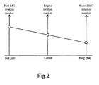
- the respective numbers of rotations of the engine 10, the first MG 11, and the second MG 12 are correlated with each other such that the respective numbers of rotations are connected with a straight line on a collinear diagram.
- the plug-in hybrid vehicle 1 includes a plurality of electronic control units (hereinafter referred to as "ECUs”), such as a hybrid vehicle ECU (hereinafter referred to as "HVECU") 2, as a multiple power control of the vehicle, an engine ECU 4 that controls the engine 10, a brake ECU 9 that controls a braking mechanism, a theft prevention ECU 6 that realizes a theft prevention function.
- ECUs electronice control units
- HVECU hybrid vehicle ECU
- the plug-in hybrid vehicle 1 also includes charge controlled device 5 that conducts charging of the battery 50 based on the charge control of the HVECU 2, described later.
- Each of the ECUs incorporates a single microcomputer or a plurality of microcomputers in each having a CPU, a ROM, and a RAM.
- the plug-in hybrid vehicle 1 includes three power feeding systems of a first power feeding system 81, a second power feeding system 82, and a third power feeding system 81 that are fed by a low voltage battery 8 (for example, DC 12 V).
- a low voltage battery 8 for example, DC 12 V
- the first power feeding system 81 is directly fed from the low voltage battery 8 even when an ignition switch IGSW is in "off' state.
- the first power feeding system 81 is coupled with ECUs of a body monitoring system, such as the theft prevention ECU 6, and the HVECU 2.
- the second power feeding system 82 is fed from the low voltage battery 8 via a power supply relay RY2 when the ignition switch IGSW is in "on" state.
- the second power feeding system 82 is coupled with ECUs to control power train systems, such as the engine ECU 4 and the brake ECU 9, and with ECUs to control body systems such as wipers and door mirrors.
- the third power feeding system 83 is fed from the low voltage battery 8 via a power supply relay RY3.
- the third power feeding system 83 is coupled with ECUs relating to the charge control of the battery 50, such as the HVECU 2 and the charge controlled device 5.
- the ECUs of power train system and the ECUs of charging system are mutually coupled via a CAN (Controller Area Network) bus.
- the ECUs of body system are mutually coupled via a LIN (Local Interconnect Network) bus.
- the CAN bus and the LIN bus are mutually coupled via a gate way. That is, the ECUs can exchange necessary control information via these communication buses.
- Each ECU includes a DC regulator to produce a control voltage on a predetermined level (for example, DC 5 V) using the direct current voltage of DC 12 V fed from the low voltage battery 8.
- the output voltage of the DC regulator is fed to a control circuit provided in each ECU, such as a microcomputer.
- the HVECU 2 controls the state of power fed from the low voltage battery 8 through the second power feeding system 82 and the third power feeding system 83 based on operation for the ignition switch IGS.
- the HVECU 2 includes a first microcomputer incorporating a sub-CPU 22 that functions as a power control unit and a second microcomputer incorporating a main CPU 21 that functions as a running control unit and charge control unit.
- the first and second microcomputers respectively include ROMs 211 and 221 in which respective control programs are stored, and RAMs 212 and 222 used as working areas during respective control operations.
- the first microcomputer and the second microcomputer respectively include a DMA controller to ensure the CPUs 21 and 22 to interactively read information stored in RAMs 212 and 222.
- the first microcomputer and the second microcomputer are coupled via a DMA communication line that enables them to communicate with each other via the DMA controllers.
- the main CPU 21 includes a nonvolatile memory to evacuate important control data from RAM when the power supply is turned off.
- the sub-CPU 22 is always fed by the first power feeding system 81 via a regulator 23.
- the sub-CPU 22 turns on a field-effect transistor (hereinafter referred to as "FET") FET1 to turn on the power supply relay RY2.
- FET field-effect transistor
- the ECUs coupled to the second power feeding system 82 are activated to execute respective, expected control actions.
- a high level control signal is input from the second power feeding system 82 to one input terminal of an OR circuit 25 via a diode D4.
- the high level signal output from the OR circuit 25 turns on a FET 2, which turns on the power supply relay RY3. This starts power feeding from the low voltage battery 8 to the third power feeding system 83 as well.
- the main CPU 21 is activated by being fed by the third power feeding system 83 via a regulator 24.
- the sub-CPU 22 Upon detecting that the ignition switch IGSW is turned off while the power supply relay RY2 is closed, the sub-CPU 22 transmits via the CAN bus an indication that the ignition switch IGSW is turned off to urge shutdown processing of the ECUs coupled to the second power feeding system 82.
- the main CPU 21 When the main CPU 21 acknowledges via the CAN bus the completion of the shutdown processing of the ECUs and completes the main CPU 21's own shutdown processing, at the same time, the main CPU 21 turns off the power supply relay RY2 via the sub-CPU 22 and thus stops the power feeding to the second power feeding system 82.
- the shutdown processing refers to stop processing for various kinds of driving actuators, evacuation processing to save control data into a memory, and the like processing in association with the ignition switch IGSW turning into "off' state.
- the shutdown processing includes stop processing for the engine 10 and saving processing to evacuate engine control data including various kinds of learning data, such as an air-fuel ratio, into a nonvolatile memory.
- standby state refers to a state in which the CPU has executed a stop order or a hold order.
- the sub-CPU 22 When an ignition switch IGSW signal is input to an interrupt terminal PIG of the sub-CPU 22 in standby state, the sub-CPU 22 returns to normal operation state from standby state, turns on the FET 1, and turns on the power supply relay RY2. That is, the ignition switch IGSW signal serves as a wakeup signal to return the sub-CPU 22 in standby state to normal state.
- the ignition switch IGSW may be any types of a momentary switch and an alternate switch.
- the HVECU 2 may hold a current situation as flag data in the RAM and determine, based on the flag data, whether the momentary switch is turned on or off, upon an operation edge of the switch.
- the ignition switch IGSW may be a conventional switch with a key that is inserted into a key cylinder to be on and off by rotation of it.
- the HVECU 2 monitors the state of charge (hereinafter referred to as "SOC (State Of Charge)) of the battery 50 via the charge controlled device 5. For example, when the SOC is lower than a predetermined value, the HVECU 2 activates the engine 10 via the engine ECU 4 and accumulates the power generated by the first MG 11, which is driven via the power separating mechanism 13, into the battery 50.
- SOC State Of Charge
- the power generated by the first MG 11 is converted from an alternate current to a direct current at an inverter 17, and the voltage of the power is adjusted at a converter 15. Then, the power is accumulated in the battery 50. In this respect, a part of the power generated by the engine 10 is transmitted to drive wheels 16 via the power separating mechanism 13 and the decelerator 14.
- the HVECU 2 drives the second MG 12 by using at least one of the power accumulated in the battery 50 and the power generated by the first MG 11, and thus assists the power of the engine 10.
- the drive force of the second MG 12 is transmitted to the drive wheels 16 via the decelerator 14.
- the HVECU 2 stops the engine 10 via the engine ECU 4 and drives the second MG 12 by using the power accumulated in the battery 50.
- the HVECU 2 controls the second MG 12 driven by the drive wheels 16 via the decelerator 14 as a generator, and accumulates the power generated by the second MG 12 into the battery 50.
- the second MG 12 is used as a regeneration brake to convert the braking energy to power.
- the HVECU 2 controls the engine 10, the first MG 11, and the second MG 12 based on torque required by the vehicle, the SOC of the battery 50, and other parameters.
- the front wheels assume the drive wheels 16 driven by the second MG 12
- the rear wheels may assume the drive wheels 16 in place of the front wheels, or both the front wheels and the rear wheels may assume the drive wheels 16.
- the high voltage battery 50 is a chargeable and dischargeable, direct current power supply and includes, for example, a secondary battery such as a nickel-hydride battery and a lithium-ion battery.
- the voltage of the battery 50 is, for example, about 200 V
- the battery 50 is chargeable with power supplied from a power supply located outside the vehicle, in addition to power generated by the first MG 11 and the second MG 12.
- the battery 50 it is possible to employ a capacitor with a large capacity.
- the battery 50 is not limited to any kind and structure insofar as the battery 50 serves as a power buffer that temporarily accumulates power generated by the first MG 11 and the second MG 12 and power supplied from a power supply located outside the vehicle, and feeds the accumulated power to the second MG 12.
- the high voltage battery 50 is coupled to the converter 15 via a system main relay SMR, and the output voltage is adjusted to a predetermined direct current voltage at the converter 15. Then, the adjusted output voltage is converted into an alternate current voltage at the first inverter 17 or the second inverter 18, and then the alternate current voltage is applied to the first MG 11 or the second MG 12.
- the converter 15 includes a reactor, two npn type transistors serving as power switching elements, and two diodes.
- the reactor is coupled to the positive electrode side of the battery 50 at one end and to the connection node between the two npn type transistors at the other end.
- the two npn type transistors are coupled in series, and the two diodes are connected in anti- parallel to the respective npn type transistors.
- npn type transistors include an IGBT (Insulated Gate Bipolar Transistor). Further, in place of the npn type transistor, a power switching element such as a power MOSFET (Metal Oxide Semiconductor Field-Effect Transistor) may be used.
- IGBT Insulated Gate Bipolar Transistor
- MOSFET Metal Oxide Semiconductor Field-Effect Transistor
- the first inverter 17 includes a U phase arm, a V phase arm, and a W phase arm that are coupled in parallel with each other.
- Each phase arm includes two npn type transistors that are coupled in series, and diodes are coupled in anti-parallel to the respective npn type transistors.
- a connection node between the two npn type transistors constituting each of the three phase arms is coupled to the tip of the coil corresponding to the first MG
- the first inverter 17 converts direct current power fed from the converter 15 into alternate current power and feeds the alternate current power to the first MG 11. Alternatively, the first inverter 17 converts alternate current power generated by the first MG 11 into direct current power and feeds the direct current power to the converter 15.
- the second inverter 18 is configured similarly to the first inverter 17, and a connection node between two npn type transistors constituting each of three phase arms is coupled to the tip of the coil corresponding to the first MG
- the second inverter 18 converts direct current power fed from the converter 15 into alternate current power and feeds the alternate current power to the second MG 12. Alternatively, the second inverter 18 converts alternate current power generated by the second MG 12 into direct current power and feeds the direct current power to the converter 15.
- the HVECU 2 controls the first MG 11 and the second MG 12 based on an accelerator operation or other operations by a driver.
- the HVECU 2 controls the power switching elements of the converter 15 to raise the output voltage of the battery 50 to a predetermined level, and controls the phase arms of the second inverter 18 to drive the second MG 12.
- the HVECU 2 controls the phase arms of the first inverter 17 to convert power generated by the first MG 11 into direct current power, and lowers the voltage at the converter 15 to charge it with the battery 50.
- the plug-in hybrid vehicle 1 includes a charge inlet 7 to connect the vehicle to a power supply outside the vehicle in order to feed charge power to the battery 50. While in Fig. 1 the charge inlet 7 is arranged at the rear side of the vehicle body, the charge inlet 7 may be arranged at the front side of the vehicle body.
- the charge controlled device 5 includes an SOC detecting device 51 that detects the SOC of the battery 50 and outputs a detection signal to the HVECU 2, a system main relay SMR that performs open/close control of connection to the battery 50, an LC filter 53 that eliminates noise from the alternate current power supplied from the outside of the vehicle, and an AC/DC converter 52 that converts the alternate current power supplied from the outside of the vehicle into direct current power.
- SOC detecting device 51 that detects the SOC of the battery 50 and outputs a detection signal to the HVECU 2
- a system main relay SMR that performs open/close control of connection to the battery 50
- an LC filter 53 that eliminates noise from the alternate current power supplied from the outside of the vehicle
- an AC/DC converter 52 that converts the alternate current power supplied from the outside of the vehicle into direct current power.
- the power supplied from the outside of the vehicle via a charge cable 3 is converted into direct current power by the AC/DC converter 52 being a charge circuit via the LC filter 54, and thereafter, is charged into the high voltage battery 50.
- the charge cable 3 includes, at one end, a plug 32 to be coupled to an outlet of an outside power supply such as a commercial power supply installed in a house, and, at the other end, an attachment 34 equipped with a connector 33 to be coupled to the charge inlet 7.
- the charge cable 3 includes a power cable 31 that supplies alternate current power from a commercial power supply; and a CCID (Charging Circuit Interrupt Device) 36.
- the CCID 36 incorporates a relay 361 to stop or relay the supply of the alternate current power via the power cable 31, and a signal generating unit 362.
- the signal generating unit 362 includes circuit blocks including an oscillator 363 that produces a pulse signal (hereinafter referred to as "control pilot signal” or “CPLT signal”) representing a rated current of the power cable 31, and a voltage detector 364 that detects the signal level of the control pilot signal.
- control pilot signal a pulse signal representing a rated current of the power cable 31
- voltage detector 364 that detects the signal level of the control pilot signal.
- the control pilot signal output from the signal generating unit 362 corresponds to the state of power supply from the outside power supply, and as such, is used to execute a series of charging processing between the CCID 36 and the HVECU 2.
- the connector 33 incorporates a connection determining circuit 331 that includes a switch 332 that is grounded at one end and a resistor R10 that is coupled in series to the switch 332.
- the output of the connection determining circuit 331 is input into the HVECU 2 as a cable connection signal PISW
- the attachment 34 includes a mechanical lock mechanism that prevents detachment of the connector 33 inserted into the charge inlet 7, and an operation unit 35 composed of an operation button to release the lock mechanism.
- the operation button is pressed to release the lock mechanism, whereby the connector 33 is detached.
- the switch 332 of the connection determining circuit 331 turns into “off” state in conjunction with the operation of the operation button, while when pressing of the operation button is released, the switch 332 returns to "on” state.
- the connector 33 of the charge cable 3 includes terminal pins of a pair of power lines coupled to the power cable 31, a ground terminal pin, a terminal pin of a signal line L1 to output the control pilot signal, and a terminal pin of a cable connection signal line that is output from the connection determining circuit 331.
- the charge inlet 7 includes a plurality of terminal pins to be coupled to the respective terminal pins provided on the connector 33 and a wiring-disconnection detecting terminal pin that is short-circuited with the control pilot signal terminal.
- the wiring-disconnection detecting terminal pin is a signal pin used to detect wiring disconnection or short circuit of a signal line L2 of the vehicle side to which the control pilot signal is transmitted.
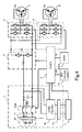
- the HVECU 2 includes a first interface circuit 26, a second interface circuit 27, and a wiring-disconnection/short-circuit detecting circuit 28 as peripheral circuits of the main CPU 21.
- the first interface circuit 26 includes a buffer circuit that inputs a control pilot signal input via a diode D1; a first step-down circuit that includes a resistor R7 and a switch SW1 and that lowers the signal level of the control pilot signal; and a second step-down circuit that includes a resistor R8 and a switch SW2.
- the main CPU 21 detects the signal level of the control pilot signal output from the charge inlet 7 via the buffer circuit of the first interface circuit 26 and changes the signal level into two stages using the first step-down circuit and/or the second step-down circuit.
- the second interface circuit 27 includes resister circuits (R1, R2, and R3) and a buffer circuit that input a low level signal to the main CPU 21 when the signal level of the control pilot signal input via the diode D2 is on a minus level, while inputting a high level control signal to the main CPU 21 when the signal level of the control pilot signal is on a plus level.
- the main CPU 21 detects the low level of the control pilot signal via the buffer circuit of the second interface circuit 27.
- the wiring-disconnection/short-circuit detecting circuit 28 is coupled to the wiring-disconnection detecting terminal pin and includes a switch SW3 to ground the wiring-disconnection detecting terminal pin via the resister R9.
- the main CPU 21 controls the switch SW3 so as to detect wiring disconnection or short circuit of the signal line L2 of the vehicle side.
- the sub-CPU 22 having returned to normal operating state from standby state upon turning on of the ignition switch IGSW, turns on the power supply relay RY2 to activate the main CPU 21.
- the sub-CPU 22 then outputs a control signal to the main CPU 21 indicating that the ignition switch IGSW is turned on.
- the main CPU 21 controls the engine 10, the first MG 11, and the second MG 12 based on the above-described torque required for the vehicle, the SOC of the battery 50, and other parameters, and conducts the running control of the vehicle.
- the main CPU 21 switches on or off the switch SW3 of the wiring-disconnection/short-circuit detecting circuit 28 so as to discriminate whether the signal line L2 of the vehicle side is disconnected or short-circuited.
- the resisters R4 and R5 cause a high level voltage on a current passage along which a current flows from the power supply to a grounded portion of the vehicle through the resisters R1, R2, and R3, the diodes D2 and D1, and the resisters R4 and R5, and then the high level voltage caused by the resisters R4 and R5 is input to the main CPU 21.
- the resister R9 causes a low level voltage on a current passage along which a current flows from the power supply to the grounded portion of the vehicle through the resisters R1, R2, and R3, the diode D2, the resister R9, and the switch SW3, and then the low level voltage caused by the resister R9 is input to the main CPU 21.
- the main CPU 21 determines that the signal line L2 is normal.
- the main CPU 21 determines that the signal line L2 is short-circuited, and when the voltage value of the signal line L2 is on a high level when the switch SW3 is turned on, the main CPU 21 determines that the signal line L2 is disconnected.
- the resister R9 is a protective resister of the switch SW3 and is set to a sufficiently low resistance value.
- the HVECU 2 conducts the above-described running control of the vehicle at the time of turning on of the ignition switch IGSW, while conducting plug-in charge control, i.e., charge control of the battery 50 via the charge cable 3 at the time of turning off of the ignition switch IGSW
- the HVECU 2 includes an edge detecting circuit 29 as a peripheral circuit of the sub-CPU 22.
- the edge detecting circuit 29 includes resisters R4, R5, and R6 to detect a rising edge (hereinafter referred to as an "on edge") of the control pilot signal.
- the output of the edge detecting circuit 29 is coupled to a wake-up interrupt terminal WU of the sub-CPU 22.
- the signal generating unit 362 outputs a control pilot signal of a direct current voltage V1 (for example, +12 V) (at time t0 in Fig. 7 ).
- the sub-CPU 22 returns to normal operating state from standby state when the control pilot signal with the direct current voltage V1 is input to the interrupt terminal WU via the signal lines L1 and L2 after a predetermined period of time when no control pilot signal is input to the interrupt terminal WU, and when the level of signal input to the interrupt terminal WU changes.
- the sub-CPU 22 wakes up upon occurrence of an "on edge" of a signal input into the interrupt terminal WU.
- the OR circuit 25 When the sub-CPU 22 that has woken up with the "on edge" of the control pilot signal outputs a high level control signal to one input terminal of the OR circuit 25, the OR circuit 25 outputs an output signal so as to turn on the FET 2, which in turn turns on the power supply relay RY3.
- the charge mode signal is DMA-transmitted to the main CPU 21 as a signal to request execution of charge control.
- the main CPU 21 Upon detecting the signal, the main CPU 21 outputs a high level signal to one input terminal of the OR circuit 25 so as to maintain the "on" state of the power supply relay RY3.
- control signal output from the sub-CPU 22 to the OR circuit 25 may be detected by the main CPU 21 as the charge mode signal.
- the main CPU 21 turns on a charge completion signal indicating that "the charge control is underway".
- the main CPU 21 DMA-transmits the state of the charge completion signal to the sub-CPU 22 at predetermined intervals via a DMA controller.
- the sub-CPU 22 Upon receipt of the "on" state charge completion signal from the main CPU 21 via the DMA controller, the sub-CPU 22 memorizes the state of the charge completion signal in the RAM 222.
- the main CPU 21 starts charge control of the battery 50 via the charge controlled device 5.
- the main CPU 21 When at time t1 the main CPU 21 detects the voltage V1 (+12 V) of the control pilot signal, the main CPU 21 turns on the switch SW2 of the second step-down circuit so as to lower the voltage level of the control pilot signal from V1 to V2 (for example, +9 V).
- the signal generating unit 362 When at time t2 the signal generating unit 362 detects via the voltage detector 364 that the signal level of the control pilot signal is lowered from V1 to V2, the signal generating unit 362 outputs a pulse signal generated in the oscillating section 363 with a predetermined duty cycle and a predetermined frequency (for example, 1 KHz) as the control pilot signal.
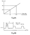
- the duty cycle of the control pilot signal is a value set based on a capacity of current that can be supplied from the outside power supply to the vehicle via the charge cable 3, and the duty cycle is set in advance on an individual charge cable basis. For example, the duty cycle is set at 20% for a charge cable with a current capacity of 12 A, and at 40% for a charge cable with a current capacity of 24 A.
- the main CPU 21 detects the duty cycle of the control pilot signal and acknowledges the current capacity of the charge cable 3. Then at time t3, the main CPU 21 closes the system main relay SMR (see Fig. 4 ), turns on the switch SW1 of the first step-down circuit with the switch SW2 of the second step-down circuit in "on” state, and lowers the voltage level of the control pilot signal from V2 to V3 (for example, +6 V).
- the signal generating unit 362 Upon detecting that the signal level of the control pilot signal is lowered from V2 to V3, the signal generating unit 362 turns on the relay 361 to supply alternate current power from the power cable 31 to the vehicle side.
- the main CPU 21 When at time t4 the main CPU 21 detects that the SOC of the battery 50 reaches the predetermined level, the main CPU 21 executes charge completing processing. This will be described in more detail below.
- the main CPU 21 stops the AC/DC converter 52 and opens the system main relay SMR (see Fig. 4 ). Further, the main CPU 21 turns off the switch SW1 of the first step-down circuit to raise the voltage level from V3 to V2.
- the signal generating unit 362 Upon detecting that that the control pilot signal is raised from V3 to V2, the signal generating unit 362 turns off the relay 361 so as to stop supply of the alternate current power to the vehicle side.
- the main CPU 21, at time t5, turns off the switch SW2 of the second step-down circuit so as to return the level of the control pilot signal to the initial level of V1.
- the main CPU 21, at time t6, sets the charge completion signal to "off' state, memorizes charge completion signal in the RAM 212, and DMA-transmits the charge completion signal to the sub-CPU 22.
- the sub-CPU 22 When at time t7 the sub-CPU 22 detects that the charge completion signal input from the main CPU 21 is in "off' state, the sub-CPU 22 switches the charge mode signal to a low level, outputs the charge mode signal to the OR circuit 25, and memorizes the state of the charge mode signal in the RAM 222.
- the main CPU 21 Upon detecting that that the charge mode signal is switched to the low level, the main CPU 21 executes shutdown processing.
- the main CPU 21, at time t8, Upon completion of the shutdown processing, the main CPU 21, at time t8, outputs a low level control signal to the OR circuit so as to turn off the power supply relay RY3.
- the sub-CPU 22 and the main CPU 21 exchange the charge mode signal and the charge completion signal so as to execute a series of charge processing.
- the sub-CPU 22 when the sub-CPU 22 detects a rising of the control pilot signal, the sub-CPU 22 wakes up from standby state and turns on the charge mode signal so as to activate charge processing in the main CPU 21.
- the main CPU 21 turns on the charge completion signal, transmits the charge completion signal to the sub-CPU 22, and charges the high voltage battery.
- the main CPU 21 turns off the charge completion signal and transmits the charge completion signal to the sub-CPU 22.
- the sub-CPU 22 turns off the charge mode signal and shifts to standby state.
- the following problems may occur if, while the main CPU 21 is charging the high voltage battery, an error occurs to DMA communication to cause abnormality such as failure to detect the charge completion signal input from the main CPU 21 with predetermined intervals, and an instantaneous stop of the power supply voltage.
- the sub-CPU 22 turns off the charge mode signal and then shifts to standby state.
- the main CPU 21 turns off the switch SW1 of the first step-down circuit to raise the voltage level from V3 to V2, and further, turns off the switch SW2 of the second step-down circuit to return the level of the control pilot signal to the initial level of V1. Then, the main CPU 21 executes the shutdown processing to turn off the power supply relay RY3.
- the signal level of the control pilot signal is maintained at the direct current voltage V1, whereby the charge processing is not performed thereafter.
- the power supply voltage of the main CPU 21 is instantaneously stopped, the signal output from the main CPU 21 to the OR circuit 25 is also turned off, thereby turning the power supply relay RY3 into "off' state. This is the case where the charge processing is not performed thereafter as well.
- the sub-CPU 22 confirms the state of the charge completion signal memorized in the RAM 222. Upon detecting that the state of the charge completion signal is set "on”, the sub-CPU 22 determines that the charging is not completed yet, in which case the sub-CPU 22 turns on again the charge mode signal.
- the main CPU 21 turns on the charge completion signal to start again the charging of the high voltage battery.
- the HVECU 2 which includes the above-described first microcomputer and second microcomputer, constitutes the control device of the embodiment of the present invention.
- the first microcomputer receives a signal that is transmitted from the signal generating unit 362 provided in the charge cable 3 and that is corresponding to a state of power supply from an outside power supply; turns on the charge mode signal when the signal changes from an unchanging state lasting for a predetermined period of time; turns off the charge mode signal upon detecting that the charge completion signal output from the second microcomputer is turned off; and turns on again the charge mode signal when the first microcomputer turns off the charge mode signal before detecting that the charge completion signal is turned off.
- the second microcomputer upon detecting the charge mode signal that is turned on by the first microcomputer, charges the battery based on power supplied from an outside power supply via a charge cable, and turns off the charge completion signal when the charging is completed.
- the main CPU 21 may control the sub-CPU 22 to turn on the charge mode signal again.
- the main CPU 21 determines that the charging is underway. Then, the main CPU 21 temporarily turns off the switch SW3 provided in the wiring-disconnection/short-circuit detecting circuit 28, and thereafter, turns on the switch SW3.
- Turning off the switch SW3 changes the voltage of the control pilot signal input to the sub-CPU 22 to a low level. Then, turning on the switch SW3 raises the voltage of the control pilot signal to V1.
- the main CPU 21 repeats such switching control of the switch SW3 for predetermined times.
- the period of time from when the switch SW3 is turned off until the switch SW3 is turned on again, and the number of times of repeating turning on/off the switch SW3 may be set appropriately.
- switch SW3 of the wiring-disconnection/short-circuit detecting circuit 28 is used to raise the control pilot signal, it is possible to couple a switch SW4 to the signal line L2 as shown in Fig. 9 so that turning off the switch SW4 secures switching of the voltage level of the signal line L2.
- the charge completion signal memorized in the RAM 222 of the sub-CPU 22 and the charge completion signal memorized in the RAM 212 of the main CPU 21 may be stored in a nonvolatile memory.
- the present invention is applicable to what we called series hybrid vehicles in which the engine 10 is used only to drive the first MG 11 and only the second MG 12 generates the vehicle driving force; hybrid vehicles in which among the motion energy generated by the engine 10, only the regeneration energy is recovered as electric energy; and "electric motor assist" hybrid vehicles using the engine 10 as main power while electric motor being used as auxiliary energy, if needed.
- the present invention is applicable to electric vehicles without an engine 10 and only with an electric motor that runs on electricity, and to fuel battery-powered vehicles that additionally include electricity-storage batteries.
Landscapes
- Engineering & Computer Science (AREA)
- Transportation (AREA)
- Mechanical Engineering (AREA)
- Power Engineering (AREA)
- Chemical & Material Sciences (AREA)
- Combustion & Propulsion (AREA)
- Life Sciences & Earth Sciences (AREA)
- Sustainable Development (AREA)
- Sustainable Energy (AREA)
- Automation & Control Theory (AREA)
- Chemical Kinetics & Catalysis (AREA)
- General Chemical & Material Sciences (AREA)
- Electrochemistry (AREA)
- Manufacturing & Machinery (AREA)
- Human Computer Interaction (AREA)
- Electric Propulsion And Braking For Vehicles (AREA)
- Charge And Discharge Circuits For Batteries Or The Like (AREA)
- Hybrid Electric Vehicles (AREA)
- Secondary Cells (AREA)
Applications Claiming Priority (2)
| Application Number | Priority Date | Filing Date | Title |
|---|---|---|---|
| JP2008264845A JP4969547B2 (ja) | 2008-10-14 | 2008-10-14 | 制御装置及び充電制御方法 |
| PCT/JP2009/065117 WO2010044317A1 (ja) | 2008-10-14 | 2009-08-28 | 制御装置及び充電制御方法 |
Publications (3)
| Publication Number | Publication Date |
|---|---|
| EP2340962A1 true EP2340962A1 (de) | 2011-07-06 |
| EP2340962A4 EP2340962A4 (de) | 2015-01-28 |
| EP2340962B1 EP2340962B1 (de) | 2018-12-26 |
Family
ID=42106484
Family Applications (1)
| Application Number | Title | Priority Date | Filing Date |
|---|---|---|---|
| EP09820495.1A Not-in-force EP2340962B1 (de) | 2008-10-14 | 2009-08-28 | Steuervorrichtung und ladesteuerungsverfahren |
Country Status (5)
| Country | Link |
|---|---|
| US (1) | US8476865B2 (de) |
| EP (1) | EP2340962B1 (de) |
| JP (1) | JP4969547B2 (de) |
| CN (1) | CN102177046B (de) |
| WO (1) | WO2010044317A1 (de) |
Cited By (2)
| Publication number | Priority date | Publication date | Assignee | Title |
|---|---|---|---|---|
| KR101299109B1 (ko) * | 2012-01-10 | 2013-08-28 | 주식회사 만도 | 전기 자동차용 충전기의 제어 시스템 및 그 방법 |
| EP2767430A4 (de) * | 2011-10-11 | 2015-12-30 | Toyota Motor Co Ltd | Ladesteuerungsvorrichtung für ein fahrzeug und fahrzeug damit |
Families Citing this family (47)
| Publication number | Priority date | Publication date | Assignee | Title |
|---|---|---|---|---|
| US8493025B2 (en) * | 2010-02-23 | 2013-07-23 | Optimization Technologies, Inc. | Electric vehicle charging station advertising systems |
| US8725330B2 (en) | 2010-06-02 | 2014-05-13 | Bryan Marc Failing | Increasing vehicle security |
| JP5246230B2 (ja) * | 2010-09-13 | 2013-07-24 | 株式会社デンソー | 車両用電子制御装置 |
| DE102010042328A1 (de) * | 2010-10-12 | 2012-04-12 | Robert Bosch Gmbh | Verfahren zum Überwachen des Ladebetriebs eines Energiespeichers in einem Fahrzeug und Ladesystem zum Laden eines Energiespeichers in einem Fahrzeug |
| JP5747491B2 (ja) * | 2010-12-08 | 2015-07-15 | ソニー株式会社 | 蓄電システム、電動車両および電力システム |
| CN103155347B (zh) * | 2010-12-13 | 2015-06-24 | 三洋电机株式会社 | 充电设备、电力存储设备以及电源设备 |
| WO2012105266A1 (ja) * | 2011-02-03 | 2012-08-09 | パナソニック株式会社 | モータ駆動装置 |
| JP5912326B2 (ja) * | 2011-08-02 | 2016-04-27 | トヨタ自動車株式会社 | 車載ゲートウェイ制御装置及び車両充電システム |
| CA2792310C (en) | 2011-10-21 | 2019-06-04 | Keihin Corporation | Electronic control unit |
| JP5878729B2 (ja) * | 2011-10-21 | 2016-03-08 | 株式会社ケーヒン | 電子制御装置 |
| JP5947518B2 (ja) * | 2011-10-21 | 2016-07-06 | 株式会社ケーヒン | 電子制御装置 |
| KR101294176B1 (ko) * | 2011-10-25 | 2013-08-08 | 기아자동차주식회사 | 배터리관리시스템의 전자파 차단을 위한 배터리시스템 |
| WO2013097824A1 (zh) | 2011-12-31 | 2013-07-04 | 深圳市比亚迪汽车研发有限公司 | 电动汽车及用于电动汽车的动力系统和电机控制器 |
| CN103187772B (zh) * | 2011-12-31 | 2016-08-17 | 比亚迪股份有限公司 | 电动汽车及电动汽车向外供电的系统 |
| JP2013219907A (ja) * | 2012-04-06 | 2013-10-24 | Denso Corp | 電力変換装置 |
| DE102013210061B4 (de) * | 2012-05-31 | 2019-06-19 | Lear Corporation | Aktivierung-durch-Steuerpilot-Schaltung für Bordbatterie-Ladevorrichtung |
| JP5673629B2 (ja) * | 2012-08-29 | 2015-02-18 | 株式会社豊田自動織機 | Lcフィルタの保護装置 |
| US9436944B2 (en) | 2012-08-29 | 2016-09-06 | Optimization Technologies, Inc. | Electric vehicle charging station mobile device payment system |
| CN103872712B (zh) * | 2012-12-13 | 2017-06-09 | 西门子公司 | 控制导引装置、充电插座、电动汽车充电设备以及系统 |
| JP5999643B2 (ja) * | 2012-12-28 | 2016-09-28 | セイコーインスツル株式会社 | 電子部品、給電装置、及び給電システム |
| US10046661B2 (en) | 2013-10-09 | 2018-08-14 | Ford Global Technologies, Llc | Detection of on-board charger connection to electric vehicle supply equipment |
| US10286800B2 (en) * | 2013-10-09 | 2019-05-14 | Ford Global Technologies, Llc | Control pilot latch-out mechanism to reduce off-board energy consumption |
| TWI506916B (zh) * | 2013-12-27 | 2015-11-01 | Generalplus Technology Inc | 適用於行動電源之無線充電電路及使用其之行動電源 |
| CN104810874B (zh) * | 2014-01-28 | 2017-04-19 | 广东欧珀移动通信有限公司 | 启动充电的检测电路和方法 |
| JP6112033B2 (ja) * | 2014-02-12 | 2017-04-12 | トヨタ自動車株式会社 | 電力授受制御装置 |
| JP2015207817A (ja) * | 2014-04-17 | 2015-11-19 | 株式会社オートネットワーク技術研究所 | 通信装置 |
| US9573476B2 (en) * | 2014-06-09 | 2017-02-21 | GM Global Technology Operations LLC | Method and apparatus for controller wakeup using control pilot signal from charge port |
| KR101592751B1 (ko) * | 2014-08-13 | 2016-02-05 | 현대자동차주식회사 | 완속충전 초기 오버 슈트 방지 장치 및 방법 |
| US10033213B2 (en) | 2014-09-30 | 2018-07-24 | Johnson Controls Technology Company | Short circuit wake-up system and method for automotive battery while in key-off position |
| JP6569122B2 (ja) * | 2015-08-05 | 2019-09-04 | 株式会社オートネットワーク技術研究所 | 車載充電システム |
| JP6601365B2 (ja) * | 2016-07-27 | 2019-11-06 | 株式会社デンソー | 制御システム |
| DE102016218599A1 (de) * | 2016-09-27 | 2018-03-29 | Robert Bosch Gmbh | Stromrichter, elektrisches Antriebssystem und Verfahren zum Aufladen eines elektrischen Energiespeichers |
| JP6551371B2 (ja) * | 2016-11-29 | 2019-07-31 | トヨタ自動車株式会社 | 自動車 |
| JP6451726B2 (ja) * | 2016-12-07 | 2019-01-16 | トヨタ自動車株式会社 | ハイブリッド自動車 |
| JP6751512B2 (ja) * | 2016-12-08 | 2020-09-09 | 株式会社オートネットワーク技術研究所 | 車載用電源装置 |
| US10661673B2 (en) * | 2016-12-20 | 2020-05-26 | Eaton Intelligent Power Limited | Pilot signal detection and indication unit and electric vehicle charging system including the same |
| JP6551424B2 (ja) * | 2017-01-10 | 2019-07-31 | トヨタ自動車株式会社 | 充電制御装置及び充電制御方法 |
| CN107627897A (zh) * | 2017-09-13 | 2018-01-26 | 北京军秀咨询有限公司 | 一种电动汽车及其集成控制系统 |
| US11070073B2 (en) | 2018-12-04 | 2021-07-20 | Mobile Escapes, Llc | Mobile power system with multiple DC-AC converters and related platforms and methods |
| CN110065405B (zh) * | 2019-03-18 | 2022-07-01 | 湖南猎豹汽车股份有限公司 | 一种车载充电机控制方法 |
| JP7093740B2 (ja) * | 2019-03-26 | 2022-06-30 | 本田技研工業株式会社 | 車載制御装置及びプログラム |
| US11368035B2 (en) * | 2020-03-27 | 2022-06-21 | Lear Corporation | Control pilot wake-up circuit for on-board charger |
| CN113056387B (zh) * | 2021-03-26 | 2022-10-18 | 华为技术有限公司 | 一种充电控制装置、方法及电动汽车 |
| CN113608003B (zh) * | 2021-06-25 | 2024-08-27 | 无锡芯朋微电子股份有限公司 | 一种电压检测电路、电源系统及芯片 |
| US12090878B2 (en) | 2021-10-30 | 2024-09-17 | Beta Air, Llc | Systems and methods for emergency shutdown of an electric aircraft port in response to a disconnection |
| US11440427B1 (en) | 2021-11-01 | 2022-09-13 | Beta Air, Llc | Systems and methods for pre-charging short circuit detection in electric aircraft |
| US12491784B2 (en) | 2021-11-01 | 2025-12-09 | Beta Air Llc | Systems and methods for pre-charging short circuit detection in electric aircraft |
Family Cites Families (8)
| Publication number | Priority date | Publication date | Assignee | Title |
|---|---|---|---|---|
| JPH06343202A (ja) * | 1993-06-01 | 1994-12-13 | Nissan Motor Co Ltd | 電気自動車の充電装置 |
| JPH06343205A (ja) * | 1993-06-01 | 1994-12-13 | Nissan Motor Co Ltd | 電気自動車の充電装置 |
| JPH10304582A (ja) | 1997-04-25 | 1998-11-13 | Toyota Motor Corp | インダクティブ充電装置およびインダクティブ充電システム |
| JP3915219B2 (ja) * | 1998-01-16 | 2007-05-16 | トヨタ自動車株式会社 | 電気自動車用充電装置 |
| DE60140854D1 (de) * | 2000-06-27 | 2010-02-04 | Fujitsu Ten Ltd | Batterielade/entladungssystem |
| JP4014212B2 (ja) * | 2003-11-19 | 2007-11-28 | 富士通テン株式会社 | 電子制御装置 |
| JP4367391B2 (ja) * | 2005-09-01 | 2009-11-18 | トヨタ自動車株式会社 | 充電制御装置および電動車両 |
| JP4517994B2 (ja) * | 2005-09-29 | 2010-08-04 | トヨタ自動車株式会社 | 充電制御装置および電動車両 |
-
2008
- 2008-10-14 JP JP2008264845A patent/JP4969547B2/ja active Active
-
2009
- 2009-08-28 WO PCT/JP2009/065117 patent/WO2010044317A1/ja not_active Ceased
- 2009-08-28 US US13/123,324 patent/US8476865B2/en active Active
- 2009-08-28 CN CN2009801398634A patent/CN102177046B/zh not_active Expired - Fee Related
- 2009-08-28 EP EP09820495.1A patent/EP2340962B1/de not_active Not-in-force
Cited By (2)
| Publication number | Priority date | Publication date | Assignee | Title |
|---|---|---|---|---|
| EP2767430A4 (de) * | 2011-10-11 | 2015-12-30 | Toyota Motor Co Ltd | Ladesteuerungsvorrichtung für ein fahrzeug und fahrzeug damit |
| KR101299109B1 (ko) * | 2012-01-10 | 2013-08-28 | 주식회사 만도 | 전기 자동차용 충전기의 제어 시스템 및 그 방법 |
Also Published As
| Publication number | Publication date |
|---|---|
| CN102177046B (zh) | 2013-10-16 |
| EP2340962B1 (de) | 2018-12-26 |
| JP4969547B2 (ja) | 2012-07-04 |
| EP2340962A4 (de) | 2015-01-28 |
| US20110193532A1 (en) | 2011-08-11 |
| JP2010098779A (ja) | 2010-04-30 |
| WO2010044317A1 (ja) | 2010-04-22 |
| US8476865B2 (en) | 2013-07-02 |
| CN102177046A (zh) | 2011-09-07 |
Similar Documents
| Publication | Publication Date | Title |
|---|---|---|
| EP2340962B1 (de) | Steuervorrichtung und ladesteuerungsverfahren | |
| US8179086B2 (en) | Control apparatus and control method | |
| US8368350B2 (en) | Control system, control device and cable connection state determining method | |
| US8198855B2 (en) | Charging cable, charging control device and vehicle charging system | |
| CN102481853B (zh) | 车辆的电源系统及具有该系统的电动车辆 | |
| CN101849339B (zh) | 电动车辆 | |
| EP1151892B1 (de) | Fahrzeug mit einer Hochspannungsstromversorgung und Verfahren zum Starten eines solchen Fahrzeugs | |
| US9614399B2 (en) | Charging control device using in-vehicle solar cell | |
| CN101909928B (zh) | 车辆的充电控制装置 | |
| JP2011004448A (ja) | 充電ケーブル、電子制御装置、及び充電ケーブルの異常検知方法 | |
| JP5301948B2 (ja) | 制御装置 | |
| WO2012049559A2 (en) | Electromotive vehicle | |
| US20150336468A1 (en) | Power supply system for vehicle, vehicle comprising the same, and method for controlling power supply system for vehicle | |
| KR20080100493A (ko) | 차량의 제어장치 및 차량 | |
| JP2010148213A (ja) | 充電制御システム、制御装置、充電制御方法及び制御方法 | |
| JP2014212643A (ja) | 車両の電源システムおよびそれを備える車両 | |
| JP2010239670A (ja) | 車両の制御装置及び制御方法 | |
| JP2010081661A (ja) | 制御装置 | |
| JP2010104141A (ja) | 制御装置、充電制御装置、及び充電制御システム | |
| US20160257296A1 (en) | Controller for hybrid vehicle | |
| JP2010148159A (ja) | 制御装置、及び、制御方法 |
Legal Events
| Date | Code | Title | Description |
|---|---|---|---|
| PUAI | Public reference made under article 153(3) epc to a published international application that has entered the european phase |
Free format text: ORIGINAL CODE: 0009012 |
|
| 17P | Request for examination filed |
Effective date: 20110509 |
|
| AK | Designated contracting states |
Kind code of ref document: A1 Designated state(s): AT BE BG CH CY CZ DE DK EE ES FI FR GB GR HR HU IE IS IT LI LT LU LV MC MK MT NL NO PL PT RO SE SI SK SM TR |
|
| AX | Request for extension of the european patent |
Extension state: AL BA RS |
|
| DAX | Request for extension of the european patent (deleted) | ||
| RAP1 | Party data changed (applicant data changed or rights of an application transferred) |
Owner name: FUJITSU TEN LIMITED Owner name: TOYOTA JIDOSHA KABUSHIKI KAISHA |
|
| A4 | Supplementary search report drawn up and despatched |
Effective date: 20150108 |
|
| RIC1 | Information provided on ipc code assigned before grant |
Ipc: H02J 7/00 20060101ALI20141222BHEP Ipc: B60L 15/00 20060101ALI20141222BHEP Ipc: B60W 50/02 20120101ALI20141222BHEP Ipc: B60L 11/18 20060101AFI20141222BHEP Ipc: H02J 7/02 20060101ALI20141222BHEP Ipc: B60L 11/12 20060101ALI20141222BHEP Ipc: B60L 11/14 20060101ALI20141222BHEP Ipc: B60W 20/00 20060101ALI20141222BHEP Ipc: B60K 6/365 20071001ALI20141222BHEP Ipc: H02J 7/10 20060101ALI20141222BHEP Ipc: H01M 16/00 20060101ALI20141222BHEP Ipc: H01M 10/44 20060101ALI20141222BHEP Ipc: B60K 1/02 20060101ALI20141222BHEP Ipc: B60W 10/08 20060101ALI20141222BHEP Ipc: B60K 6/445 20071001ALI20141222BHEP Ipc: B60W 10/26 20060101ALI20141222BHEP |
|
| GRAP | Despatch of communication of intention to grant a patent |
Free format text: ORIGINAL CODE: EPIDOSNIGR1 |
|
| STAA | Information on the status of an ep patent application or granted ep patent |
Free format text: STATUS: GRANT OF PATENT IS INTENDED |
|
| INTG | Intention to grant announced |
Effective date: 20180718 |
|
| GRAS | Grant fee paid |
Free format text: ORIGINAL CODE: EPIDOSNIGR3 |
|
| GRAA | (expected) grant |
Free format text: ORIGINAL CODE: 0009210 |
|
| STAA | Information on the status of an ep patent application or granted ep patent |
Free format text: STATUS: THE PATENT HAS BEEN GRANTED |
|
| AK | Designated contracting states |
Kind code of ref document: B1 Designated state(s): AT BE BG CH CY CZ DE DK EE ES FI FR GB GR HR HU IE IS IT LI LT LU LV MC MK MT NL NO PL PT RO SE SI SK SM TR |
|
| REG | Reference to a national code |
Ref country code: GB Ref legal event code: FG4D |
|
| REG | Reference to a national code |
Ref country code: CH Ref legal event code: EP |
|
| REG | Reference to a national code |
Ref country code: AT Ref legal event code: REF Ref document number: 1080932 Country of ref document: AT Kind code of ref document: T Effective date: 20190115 |
|
| REG | Reference to a national code |
Ref country code: DE Ref legal event code: R096 Ref document number: 602009056438 Country of ref document: DE Ref country code: DE Ref legal event code: R079 Ref document number: 602009056438 Country of ref document: DE Free format text: PREVIOUS MAIN CLASS: B60L0011180000 Ipc: B60L0050500000 |
|
| REG | Reference to a national code |
Ref country code: IE Ref legal event code: FG4D |
|
| REG | Reference to a national code |
Ref country code: CH Ref legal event code: PK Free format text: BERICHTIGUNGEN |
|
| RIC2 | Information provided on ipc code assigned after grant |
Ipc: H02J 7/00 20060101ALI20141222BHEP Ipc: B60W 50/02 20120101ALI20141222BHEP Ipc: B60K 6/365 20071001ALI20141222BHEP Ipc: B60L 11/14 20060101ALI20141222BHEP Ipc: H02J 7/02 20160101ALI20141222BHEP Ipc: B60L 11/18 20060101AFI20141222BHEP Ipc: H01M 16/00 20060101ALI20141222BHEP Ipc: B60K 1/02 20060101ALI20141222BHEP Ipc: B60L 15/00 20060101ALI20141222BHEP Ipc: B60L 11/12 20060101ALI20141222BHEP Ipc: B60W 10/08 20060101ALI20141222BHEP Ipc: B60W 10/26 20060101ALI20141222BHEP Ipc: B60W 20/00 20160101ALI20141222BHEP Ipc: B60K 6/445 20071001ALI20141222BHEP Ipc: H01M 10/44 20060101ALI20141222BHEP Ipc: H02J 7/10 20060101ALI20141222BHEP |
|
| PG25 | Lapsed in a contracting state [announced via postgrant information from national office to epo] |
Ref country code: BG Free format text: LAPSE BECAUSE OF FAILURE TO SUBMIT A TRANSLATION OF THE DESCRIPTION OR TO PAY THE FEE WITHIN THE PRESCRIBED TIME-LIMIT Effective date: 20190326 Ref country code: NO Free format text: LAPSE BECAUSE OF FAILURE TO SUBMIT A TRANSLATION OF THE DESCRIPTION OR TO PAY THE FEE WITHIN THE PRESCRIBED TIME-LIMIT Effective date: 20190326 Ref country code: FI Free format text: LAPSE BECAUSE OF FAILURE TO SUBMIT A TRANSLATION OF THE DESCRIPTION OR TO PAY THE FEE WITHIN THE PRESCRIBED TIME-LIMIT Effective date: 20181226 Ref country code: LT Free format text: LAPSE BECAUSE OF FAILURE TO SUBMIT A TRANSLATION OF THE DESCRIPTION OR TO PAY THE FEE WITHIN THE PRESCRIBED TIME-LIMIT Effective date: 20181226 Ref country code: LV Free format text: LAPSE BECAUSE OF FAILURE TO SUBMIT A TRANSLATION OF THE DESCRIPTION OR TO PAY THE FEE WITHIN THE PRESCRIBED TIME-LIMIT Effective date: 20181226 Ref country code: HR Free format text: LAPSE BECAUSE OF FAILURE TO SUBMIT A TRANSLATION OF THE DESCRIPTION OR TO PAY THE FEE WITHIN THE PRESCRIBED TIME-LIMIT Effective date: 20181226 |
|
| REG | Reference to a national code |
Ref country code: NL Ref legal event code: MP Effective date: 20181226 |
|
| REG | Reference to a national code |
Ref country code: LT Ref legal event code: MG4D |
|
| PG25 | Lapsed in a contracting state [announced via postgrant information from national office to epo] |
Ref country code: SE Free format text: LAPSE BECAUSE OF FAILURE TO SUBMIT A TRANSLATION OF THE DESCRIPTION OR TO PAY THE FEE WITHIN THE PRESCRIBED TIME-LIMIT Effective date: 20181226 Ref country code: GR Free format text: LAPSE BECAUSE OF FAILURE TO SUBMIT A TRANSLATION OF THE DESCRIPTION OR TO PAY THE FEE WITHIN THE PRESCRIBED TIME-LIMIT Effective date: 20190327 |
|
| REG | Reference to a national code |
Ref country code: AT Ref legal event code: MK05 Ref document number: 1080932 Country of ref document: AT Kind code of ref document: T Effective date: 20181226 |
|
| PG25 | Lapsed in a contracting state [announced via postgrant information from national office to epo] |
Ref country code: NL Free format text: LAPSE BECAUSE OF FAILURE TO SUBMIT A TRANSLATION OF THE DESCRIPTION OR TO PAY THE FEE WITHIN THE PRESCRIBED TIME-LIMIT Effective date: 20181226 |
|
| PG25 | Lapsed in a contracting state [announced via postgrant information from national office to epo] |
Ref country code: PL Free format text: LAPSE BECAUSE OF FAILURE TO SUBMIT A TRANSLATION OF THE DESCRIPTION OR TO PAY THE FEE WITHIN THE PRESCRIBED TIME-LIMIT Effective date: 20181226 Ref country code: PT Free format text: LAPSE BECAUSE OF FAILURE TO SUBMIT A TRANSLATION OF THE DESCRIPTION OR TO PAY THE FEE WITHIN THE PRESCRIBED TIME-LIMIT Effective date: 20190426 Ref country code: ES Free format text: LAPSE BECAUSE OF FAILURE TO SUBMIT A TRANSLATION OF THE DESCRIPTION OR TO PAY THE FEE WITHIN THE PRESCRIBED TIME-LIMIT Effective date: 20181226 Ref country code: CZ Free format text: LAPSE BECAUSE OF FAILURE TO SUBMIT A TRANSLATION OF THE DESCRIPTION OR TO PAY THE FEE WITHIN THE PRESCRIBED TIME-LIMIT Effective date: 20181226 Ref country code: IT Free format text: LAPSE BECAUSE OF FAILURE TO SUBMIT A TRANSLATION OF THE DESCRIPTION OR TO PAY THE FEE WITHIN THE PRESCRIBED TIME-LIMIT Effective date: 20181226 |
|
| PG25 | Lapsed in a contracting state [announced via postgrant information from national office to epo] |
Ref country code: SM Free format text: LAPSE BECAUSE OF FAILURE TO SUBMIT A TRANSLATION OF THE DESCRIPTION OR TO PAY THE FEE WITHIN THE PRESCRIBED TIME-LIMIT Effective date: 20181226 Ref country code: EE Free format text: LAPSE BECAUSE OF FAILURE TO SUBMIT A TRANSLATION OF THE DESCRIPTION OR TO PAY THE FEE WITHIN THE PRESCRIBED TIME-LIMIT Effective date: 20181226 Ref country code: SK Free format text: LAPSE BECAUSE OF FAILURE TO SUBMIT A TRANSLATION OF THE DESCRIPTION OR TO PAY THE FEE WITHIN THE PRESCRIBED TIME-LIMIT Effective date: 20181226 Ref country code: IS Free format text: LAPSE BECAUSE OF FAILURE TO SUBMIT A TRANSLATION OF THE DESCRIPTION OR TO PAY THE FEE WITHIN THE PRESCRIBED TIME-LIMIT Effective date: 20190426 Ref country code: RO Free format text: LAPSE BECAUSE OF FAILURE TO SUBMIT A TRANSLATION OF THE DESCRIPTION OR TO PAY THE FEE WITHIN THE PRESCRIBED TIME-LIMIT Effective date: 20181226 |
|
| REG | Reference to a national code |
Ref country code: DE Ref legal event code: R097 Ref document number: 602009056438 Country of ref document: DE |
|
| PG25 | Lapsed in a contracting state [announced via postgrant information from national office to epo] |
Ref country code: DK Free format text: LAPSE BECAUSE OF FAILURE TO SUBMIT A TRANSLATION OF THE DESCRIPTION OR TO PAY THE FEE WITHIN THE PRESCRIBED TIME-LIMIT Effective date: 20181226 Ref country code: AT Free format text: LAPSE BECAUSE OF FAILURE TO SUBMIT A TRANSLATION OF THE DESCRIPTION OR TO PAY THE FEE WITHIN THE PRESCRIBED TIME-LIMIT Effective date: 20181226 |
|
| PLBE | No opposition filed within time limit |
Free format text: ORIGINAL CODE: 0009261 |
|
| STAA | Information on the status of an ep patent application or granted ep patent |
Free format text: STATUS: NO OPPOSITION FILED WITHIN TIME LIMIT |
|
| 26N | No opposition filed |
Effective date: 20190927 |
|
| PG25 | Lapsed in a contracting state [announced via postgrant information from national office to epo] |
Ref country code: SI Free format text: LAPSE BECAUSE OF FAILURE TO SUBMIT A TRANSLATION OF THE DESCRIPTION OR TO PAY THE FEE WITHIN THE PRESCRIBED TIME-LIMIT Effective date: 20181226 |
|
| PG25 | Lapsed in a contracting state [announced via postgrant information from national office to epo] |
Ref country code: TR Free format text: LAPSE BECAUSE OF FAILURE TO SUBMIT A TRANSLATION OF THE DESCRIPTION OR TO PAY THE FEE WITHIN THE PRESCRIBED TIME-LIMIT Effective date: 20181226 |
|
| GBPC | Gb: european patent ceased through non-payment of renewal fee |
Effective date: 20190828 |
|
| PG25 | Lapsed in a contracting state [announced via postgrant information from national office to epo] |
Ref country code: LU Free format text: LAPSE BECAUSE OF NON-PAYMENT OF DUE FEES Effective date: 20190828 Ref country code: LI Free format text: LAPSE BECAUSE OF NON-PAYMENT OF DUE FEES Effective date: 20190831 Ref country code: MC Free format text: LAPSE BECAUSE OF FAILURE TO SUBMIT A TRANSLATION OF THE DESCRIPTION OR TO PAY THE FEE WITHIN THE PRESCRIBED TIME-LIMIT Effective date: 20181226 Ref country code: CH Free format text: LAPSE BECAUSE OF NON-PAYMENT OF DUE FEES Effective date: 20190831 |
|
| REG | Reference to a national code |
Ref country code: BE Ref legal event code: MM Effective date: 20190831 |
|
| PG25 | Lapsed in a contracting state [announced via postgrant information from national office to epo] |
Ref country code: IE Free format text: LAPSE BECAUSE OF NON-PAYMENT OF DUE FEES Effective date: 20190828 |
|
| PG25 | Lapsed in a contracting state [announced via postgrant information from national office to epo] |
Ref country code: BE Free format text: LAPSE BECAUSE OF NON-PAYMENT OF DUE FEES Effective date: 20190831 Ref country code: GB Free format text: LAPSE BECAUSE OF NON-PAYMENT OF DUE FEES Effective date: 20190828 |
|
| REG | Reference to a national code |
Ref country code: DE Ref legal event code: R082 Ref document number: 602009056438 Country of ref document: DE Representative=s name: HL KEMPNER PATENTANWAELTE, SOLICITORS (ENGLAND, DE Ref country code: DE Ref legal event code: R082 Ref document number: 602009056438 Country of ref document: DE Representative=s name: HL KEMPNER PATENTANWALT, RECHTSANWALT, SOLICIT, DE |
|
| PG25 | Lapsed in a contracting state [announced via postgrant information from national office to epo] |
Ref country code: CY Free format text: LAPSE BECAUSE OF FAILURE TO SUBMIT A TRANSLATION OF THE DESCRIPTION OR TO PAY THE FEE WITHIN THE PRESCRIBED TIME-LIMIT Effective date: 20181226 |
|
| PG25 | Lapsed in a contracting state [announced via postgrant information from national office to epo] |
Ref country code: MT Free format text: LAPSE BECAUSE OF FAILURE TO SUBMIT A TRANSLATION OF THE DESCRIPTION OR TO PAY THE FEE WITHIN THE PRESCRIBED TIME-LIMIT Effective date: 20181226 Ref country code: HU Free format text: LAPSE BECAUSE OF FAILURE TO SUBMIT A TRANSLATION OF THE DESCRIPTION OR TO PAY THE FEE WITHIN THE PRESCRIBED TIME-LIMIT; INVALID AB INITIO Effective date: 20090828 |
|
| PG25 | Lapsed in a contracting state [announced via postgrant information from national office to epo] |
Ref country code: MK Free format text: LAPSE BECAUSE OF FAILURE TO SUBMIT A TRANSLATION OF THE DESCRIPTION OR TO PAY THE FEE WITHIN THE PRESCRIBED TIME-LIMIT Effective date: 20181226 |
|
| PGFP | Annual fee paid to national office [announced via postgrant information from national office to epo] |
Ref country code: DE Payment date: 20220819 Year of fee payment: 14 |
|
| PGFP | Annual fee paid to national office [announced via postgrant information from national office to epo] |
Ref country code: FR Payment date: 20220823 Year of fee payment: 14 |
|
| REG | Reference to a national code |
Ref country code: DE Ref legal event code: R119 Ref document number: 602009056438 Country of ref document: DE |
|
| PG25 | Lapsed in a contracting state [announced via postgrant information from national office to epo] |
Ref country code: FR Free format text: LAPSE BECAUSE OF NON-PAYMENT OF DUE FEES Effective date: 20230831 Ref country code: DE Free format text: LAPSE BECAUSE OF NON-PAYMENT OF DUE FEES Effective date: 20240301 |