EP2343135A2 - Réseau de capteurs ultrasonores, instrument d'inspection ultrasonore et procédé d'inspection ultrasonore - Google Patents
Réseau de capteurs ultrasonores, instrument d'inspection ultrasonore et procédé d'inspection ultrasonore Download PDFInfo
- Publication number
- EP2343135A2 EP2343135A2 EP11156669A EP11156669A EP2343135A2 EP 2343135 A2 EP2343135 A2 EP 2343135A2 EP 11156669 A EP11156669 A EP 11156669A EP 11156669 A EP11156669 A EP 11156669A EP 2343135 A2 EP2343135 A2 EP 2343135A2
- Authority
- EP
- European Patent Office
- Prior art keywords
- ultrasonic
- crack
- sensor
- inspection
- receiver
- Prior art date
- Legal status (The legal status is an assumption and is not a legal conclusion. Google has not performed a legal analysis and makes no representation as to the accuracy of the status listed.)
- Withdrawn
Links
Images







Classifications
-
- B—PERFORMING OPERATIONS; TRANSPORTING
- B06—GENERATING OR TRANSMITTING MECHANICAL VIBRATIONS IN GENERAL
- B06B—METHODS OR APPARATUS FOR GENERATING OR TRANSMITTING MECHANICAL VIBRATIONS OF INFRASONIC, SONIC, OR ULTRASONIC FREQUENCY, e.g. FOR PERFORMING MECHANICAL WORK IN GENERAL
- B06B1/00—Methods or apparatus for generating mechanical vibrations of infrasonic, sonic, or ultrasonic frequency
- B06B1/02—Methods or apparatus for generating mechanical vibrations of infrasonic, sonic, or ultrasonic frequency making use of electrical energy
- B06B1/06—Methods or apparatus for generating mechanical vibrations of infrasonic, sonic, or ultrasonic frequency making use of electrical energy operating with piezoelectric effect or with electrostriction
-
- G—PHYSICS
- G01—MEASURING; TESTING
- G01N—INVESTIGATING OR ANALYSING MATERIALS BY DETERMINING THEIR CHEMICAL OR PHYSICAL PROPERTIES
- G01N29/00—Investigating or analysing materials by the use of ultrasonic, sonic or infrasonic waves; Visualisation of the interior of objects by transmitting ultrasonic or sonic waves through the object
- G01N29/22—Details, e.g. general constructional or apparatus details
- G01N29/24—Probes
-
- G—PHYSICS
- G01—MEASURING; TESTING
- G01N—INVESTIGATING OR ANALYSING MATERIALS BY DETERMINING THEIR CHEMICAL OR PHYSICAL PROPERTIES
- G01N29/00—Investigating or analysing materials by the use of ultrasonic, sonic or infrasonic waves; Visualisation of the interior of objects by transmitting ultrasonic or sonic waves through the object
- G01N29/22—Details, e.g. general constructional or apparatus details
- G01N29/26—Arrangements for orientation or scanning by relative movement of the head and the sensor
-
- G—PHYSICS
- G01—MEASURING; TESTING
- G01N—INVESTIGATING OR ANALYSING MATERIALS BY DETERMINING THEIR CHEMICAL OR PHYSICAL PROPERTIES
- G01N2291/00—Indexing codes associated with group G01N29/00
- G01N2291/02—Indexing codes associated with the analysed material
- G01N2291/028—Material parameters
- G01N2291/0289—Internal structure, e.g. defects, grain size, texture
-
- G—PHYSICS
- G01—MEASURING; TESTING
- G01N—INVESTIGATING OR ANALYSING MATERIALS BY DETERMINING THEIR CHEMICAL OR PHYSICAL PROPERTIES
- G01N2291/00—Indexing codes associated with group G01N29/00
- G01N2291/04—Wave modes and trajectories
- G01N2291/044—Internal reflections (echoes), e.g. on walls or defects
Definitions
- the present invention relates to the field of ultrasonic inspection technology.
- the ultrasonic reception signals (electric signals) are amplified by the receiver-side amplifiers 12 and supplied to the reception signal processing unit 8 (Step h ) (here, the receiver-side amplifiers 12 and the reception signal processing unit 8 may be replaced by each other so that the signals are added and synthesized in the reception signal processing unit 8 and then the synthesized signal is amplified by one receiver-side amplifier 12).
- the receiving timing Trimn for synthesizing the ultrasonic reception signals (electric signals) is controlled on the basis of the relation (distance relation) between the focus point 17 (Fmn) of reception of each element O, P, Q, R of the receiver element array 19 and the position of each element O, P, Q, R of the receiver element array 19, and then the ultrasonic reception signals (electric signals) are added to create one ultrasonic reception signal (Step i ).
- the transmitting timing and the receiving timing of ultrasonic waves are calculated by the ultrasonic control unit 3 so that the focus point of the ultrasonic waves 16 is identical with the focus point of reception thereof.
- Control signals obtained thus are supplied to the transmitter element control unit 7 and the reception signal processing unit 8 so as to be processed.
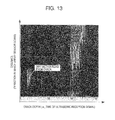
- Fig. 13 shows a typical example of inspection information including a crack signal displayed on the display unit 6 in such a case.
- the abscissa designates the time of the ultrasonic reception signal (electric signal) and the ordinate designates the distance in the scanning direction of the sensor 14.
- the shading distribution on this two-dimensional coordinates expresses the intensity of the ultrasonic reception signal (electric signal).
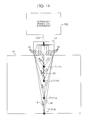
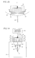
- Fig. 14 shows another example in which the ultrasonic inspection instrument according to the embodiment of the present invention is applied to crack detection and crack sizing.
- the manner when the lower tip of the crack 22 was known to some extent was described above. In actual inspection, however, only initial information that an opening of the crack 22 is present in the surface of the inspection-target material 21 can be often obtained by visual inspection with a camera or the like. That is, an ultrasonic inspection test is often performed in the state where the depth of the crack 22, that is, the position of the lower tip of the crack 22 is not known.
- Fig. 14 shows an example in which an ultrasonic inspection test is performed in such a state that the depth of the crack 22 is not known. Description will be made below in detail.
- Table 1 shows typical setting of the gains of the transmitter-side amplifiers 11.
- AT1 to AT4 designate the amplifier names of the transmitter-side amplifiers 11 respectively, with each amplifier connected to its corresponding element.
- F11 to F14 designate the focus points 17 for transmission and reception, in order of increasing depth of the focus points 17.
- the gain of each amplifier AT1 to AT4 at a focus point is G.
- the gain of the amplifier AT1 at the focus point F11 is GA1
- the gain of the amplifier AT1 at the focus point F14 is GD1.
- the gain of each amplifier is characterized in that the gain is optimized in accordance with the depth of the focus point, and set to increase in proportion to the depth of the focus point (GA ⁇ GB ⁇ GC ⁇ GD).
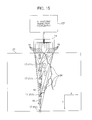
- Fig. 15 shows another example in which the ultrasonic inspection instrument according to the embodiment of the present invention is applied to crack detection and crack sizing. As described above, the example of Fig. 14 has showed a crack detection and crack sizing method in the case where a crack 22 had developed just under the sensor 14.
- Fig. 15 shows an example in which an ultrasonic inspection test is carried out when the developed shape of a crack is not known. Description will be made below in detail on the example. The procedure of crack inspection and sizing will be described below.
- the sensor 14 is pressed just above the surface opening portion of a crack 24 appearing in the inspection-target material 21 and developing obliquely or branching at the crack tip.
- Fig. 16 shows an example in which the ultrasonic inspection instrument using the sensor 14 suitable for crack detection and crack sizing of the near surface crack 22 is applied to the inconel weld metal 29.
- the sensor 14 can be placed on the top of the near surface crack 22 so as to achieve crack detection and crack sizing applicable to the inconel weld metal 29.
- a crack sizing method will be described with reference to Fig. 16 .
- a portion having a known thickness t such as the shroud support 25 in Fig. 16
- an ultrasonic wave radiated from the sensor 14 is reflected on the bottom surface as an opposite surface.
- the ultrasonic wave returns.
- the acoustic velocity in the material can be estimated.
- Crack sizing can be performed on the basis of the relation between the acoustic velocity and the time when a diffraction echo appears.
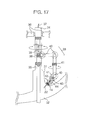
- a signal cable of the sensor 14, a signal cable, a power cable and a high-pressure water hose of the articulated manipulator 33, and so on, are bundled as a cable and hose bundle 37 in the upper portion of the inspection unit 34, and drawn out to an operation floor which is an operation/control site located on the top. Then, the cables and the hoses are connected to their corresponding control units respectively.
- the compliance mechanism 44 can be displaced in the three X-, Y- and Z-axes.
- the array sensor 14 can be made to smoothly follow the curved surfaces of the CRD stub tubes 31, the pressure vessel 32, the weld portions between the CRD stub tubes 31 and the pressure vessel 32, and so on.
- crack detection and crack sizing of the crack 22 can be achieved by use of the aforementioned crack detection and crack sizing method.
- the thrusters 48 are thrusters for controlling the posture of the suspended inspection instrument 45. By controlling the rotation direction and the rotation number of each thruster 48, the posture of the suspended inspection instrument 45 can be changed.
- the crud removing and collecting unit 49 is a unit for removing and sucking deposits such as crud deposited on the portion to be inspected.
- the crud removing and collecting unit 49 is constituted by a rolling brush for removing deposits and a device for collecting the separated deposits. By removing deposits such as crud or the like by use of the crud removing and collecting unit 49, a crack (near surface crack) lying under the deposits such as crud or the like can be found.
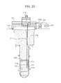
- the suspended inspection instrument 45 when the suspended inspection instrument 45 is operated remotely while being allowed to swim in a self-propelled manner, the mobility of the suspended inspection instrument 45 is enhanced, and the inspection range is expanded. That is, the underwater inspection instrument mounted with the sensor 14, the two underwater CCD cameras 46, the illuminations 47, the thrusters 48 and the crud removing and collecting unit 49 may be allowed to swim in a self-propelled manner and to be operated remotely. On that occasion, a structure shown in Fig. 20 can be adopted as the fundamental structure of the underwater inspection instrument.
- the operations including the rotation of the mast 114, the up/down motion, development and storage of the pantograph mechanism 113, and so on, are controlled by an inspection/repair unit controller 124 on the operation floor 118, and control signals are transmitted through the signal cable 123.
- the sensor 14 included in the inspection head 111 is controlled by the ultrasonic inspection instrument body 122, and a control signal is transmitted through the cable 123 between the sensor 14 and the ultrasonic inspection instrument body 122.
Landscapes
- Physics & Mathematics (AREA)
- Health & Medical Sciences (AREA)
- Life Sciences & Earth Sciences (AREA)
- Chemical & Material Sciences (AREA)
- Analytical Chemistry (AREA)
- Biochemistry (AREA)
- General Health & Medical Sciences (AREA)
- General Physics & Mathematics (AREA)
- Immunology (AREA)
- Pathology (AREA)
- Engineering & Computer Science (AREA)
- Mechanical Engineering (AREA)
- Investigating Or Analyzing Materials By The Use Of Ultrasonic Waves (AREA)
- Monitoring And Testing Of Nuclear Reactors (AREA)
Applications Claiming Priority (2)
| Application Number | Priority Date | Filing Date | Title |
|---|---|---|---|
| JP2002316971 | 2002-10-31 | ||
| EP03025101A EP1415731A3 (fr) | 2002-10-31 | 2003-10-31 | Réseau de capteurs ultrasonores, instrument d'inspection ultrasonore et procédé d'inspection ultrasonore |
Related Parent Applications (1)
| Application Number | Title | Priority Date | Filing Date |
|---|---|---|---|
| EP03025101.1 Division | 2003-10-31 |
Publications (2)
| Publication Number | Publication Date |
|---|---|
| EP2343135A2 true EP2343135A2 (fr) | 2011-07-13 |
| EP2343135A3 EP2343135A3 (fr) | 2012-08-15 |
Family
ID=32089562
Family Applications (3)
| Application Number | Title | Priority Date | Filing Date |
|---|---|---|---|
| EP03025101A Withdrawn EP1415731A3 (fr) | 2002-10-31 | 2003-10-31 | Réseau de capteurs ultrasonores, instrument d'inspection ultrasonore et procédé d'inspection ultrasonore |
| EP11156669A Withdrawn EP2343135A3 (fr) | 2002-10-31 | 2003-10-31 | Réseau de capteurs ultrasonores, instrument d'inspection ultrasonore et procédé d'inspection ultrasonore |
| EP11156667A Withdrawn EP2329890A3 (fr) | 2002-10-31 | 2003-10-31 | Réseau de capteurs ultrasonores, instrument d'inspection ultrasonore et procédé d'inspection ultrasonore |
Family Applications Before (1)
| Application Number | Title | Priority Date | Filing Date |
|---|---|---|---|
| EP03025101A Withdrawn EP1415731A3 (fr) | 2002-10-31 | 2003-10-31 | Réseau de capteurs ultrasonores, instrument d'inspection ultrasonore et procédé d'inspection ultrasonore |
Family Applications After (1)
| Application Number | Title | Priority Date | Filing Date |
|---|---|---|---|
| EP11156667A Withdrawn EP2329890A3 (fr) | 2002-10-31 | 2003-10-31 | Réseau de capteurs ultrasonores, instrument d'inspection ultrasonore et procédé d'inspection ultrasonore |
Country Status (4)
| Country | Link |
|---|---|
| US (1) | US6957583B2 (fr) |
| EP (3) | EP1415731A3 (fr) |
| JP (3) | JP5111277B2 (fr) |
| KR (1) | KR101004123B1 (fr) |
Families Citing this family (43)
| Publication number | Priority date | Publication date | Assignee | Title |
|---|---|---|---|---|
| US7388810B2 (en) * | 2005-03-23 | 2008-06-17 | Viren Pty Limited | Ultrasonic distance measurement system |
| FR2888327B1 (fr) * | 2005-07-05 | 2008-07-04 | Saipem S A Sa | Procede et dispositif de controle de soudure de raccordement de conduite par sonde a ultrasons |
| JP4544240B2 (ja) * | 2005-11-21 | 2010-09-15 | Jfeスチール株式会社 | 管体の超音波探傷装置および超音波探傷方法 |
| DE102006010010A1 (de) * | 2006-03-04 | 2007-09-06 | Intelligendt Systems & Services Gmbh & Co Kg | Verfahren zur Ultraschallprüfung eines Werkstückes in einem gekrümmten Bereich seiner Oberfläche und zur Durchführung des Verfahrens geeignete Prüfanordnung |
| DE102006020352A1 (de) | 2006-04-28 | 2007-10-31 | Intelligendt Systems & Services Gmbh & Co Kg | Verfahren und Einrichtung zum Prüfen einer an der Innenoberfläche eines Reaktordruckbehälters befindlichen Schweißnaht |
| DE102006029435A1 (de) * | 2006-06-20 | 2008-01-10 | BAM Bundesanstalt für Materialforschung und -prüfung | Vorrichtung zur zerstörungsfreien Prüfung von Bauteilen |
| CN101396282B (zh) * | 2007-09-29 | 2013-03-27 | 深圳迈瑞生物医疗电子股份有限公司 | 用于超声成像的圆弧宽波束发射方法与装置 |
| JP5065846B2 (ja) * | 2007-10-12 | 2012-11-07 | 株式会社東芝 | タービン発電機エンドリングの欠陥検出方法 |
| JP2009229355A (ja) * | 2008-03-25 | 2009-10-08 | Toshiba Corp | 原子炉振動監視装置及びその方法 |
| EP2281255A4 (fr) * | 2008-04-17 | 2013-02-20 | Travelers Indemnity Co | Procédé et système pour déterminer et traiter des informations de condition de structure d' objet |
| JP5371298B2 (ja) * | 2008-07-04 | 2013-12-18 | 本田技研工業株式会社 | 圧力タンク及び圧力タンクにおける内部欠陥検出方法 |
| US8215173B2 (en) * | 2008-08-05 | 2012-07-10 | Roger Spencer | UT method of identifying a stuck joint |
| JP5709357B2 (ja) * | 2009-02-26 | 2015-04-30 | 三菱重工業株式会社 | 超音波探傷装置および超音波探傷方法 |
| KR101214458B1 (ko) * | 2010-01-18 | 2012-12-21 | 주식회사 휴먼스캔 | 초음파 프로브 |
| US8746070B2 (en) | 2011-04-08 | 2014-06-10 | Tejas Testing & Inspection, Inc. | Phased array ultrasonic examination system and method |
| US9063059B2 (en) | 2011-05-10 | 2015-06-23 | Edison Welding Institute, Inc. | Three-dimensional matrix phased array spot weld inspection system |
| US9759691B2 (en) * | 2011-05-10 | 2017-09-12 | Cumberland & Western Resources, Llc | Gating methods for use in weld inspection systems |
| US8770029B2 (en) * | 2011-10-04 | 2014-07-08 | General Electric Company | Method and apparatus for ultrasonic testing |
| JP5840910B2 (ja) * | 2011-10-17 | 2016-01-06 | 日立Geニュークリア・エナジー株式会社 | 超音波探傷方法 |
| US10319484B1 (en) | 2011-11-17 | 2019-06-11 | Nuscale Power, Llc | Method for imaging a nuclear reactor |
| US9213019B2 (en) * | 2011-11-18 | 2015-12-15 | General Electric Company | Method of determining a size of a defect using an ultrasonic linear phased array |
| US10054676B2 (en) | 2012-05-03 | 2018-08-21 | Los Alamos National Security, Llc | Acoustic camera |
| US9437333B2 (en) * | 2012-10-09 | 2016-09-06 | Westinghouse Electric Company Llc | Apparatus and method to control sensor position in limited access areas within a nuclear reactor |
| DE102012112120B4 (de) * | 2012-12-11 | 2025-07-03 | Baker Hughes Digital Solutions Gmbh | Verfahren und Vorrichtung zur oberflächennahen zerstörungsfreien Prüfung eines rotationssymmetrischen Werkstücks mit abschnittsweise wechselndem Durchmesser mittels Ultraschall |
| JP2015045536A (ja) * | 2013-08-27 | 2015-03-12 | 関電プラント株式会社 | 小口径配管点検装置及びその点検方法 |
| FR3011635B1 (fr) * | 2013-10-09 | 2017-01-27 | Areva | Sonde a ultrasons pour l'examen d'un objet par ultrasons et procede d'examen correspondant |
| JP6463962B2 (ja) * | 2014-12-15 | 2019-02-06 | 株式会社日立製作所 | 超音波探傷システム及び検査方法 |
| KR101530337B1 (ko) * | 2015-03-13 | 2015-06-22 | 주식회사 아거스 | 압력용기 카테고리 용접부 전용 자동 위상배열 초음파 검사장치 |
| WO2016172178A1 (fr) * | 2015-04-20 | 2016-10-27 | Edison Welding Institute, Inc. | Procédés de déclenchement devant être utilisés dans des systèmes d'inspection de soudure |
| US9759813B2 (en) * | 2015-06-22 | 2017-09-12 | Appetite Lab Inc. | Devices and methods for locating and visualizing underwater objects |
| KR101736641B1 (ko) * | 2015-12-24 | 2017-05-17 | 주식회사 포스코 | 균열 측정 장치 및 방법 |
| WO2017199544A1 (fr) | 2016-05-17 | 2017-11-23 | 株式会社東芝 | Système, dispositif et procédé d'évaluation de structure |
| KR20190070324A (ko) * | 2016-10-19 | 2019-06-20 | 프로체크 아게 | 초음파 테스트에서 커플링 불균일성을 보상하기 위한 방법 및 디바이스 |
| CN108170322B (zh) * | 2018-01-03 | 2021-12-03 | 京东方科技集团股份有限公司 | 触控面板及显示装置 |
| JP7109980B2 (ja) * | 2018-04-26 | 2022-08-01 | 株式会社東芝 | 超音波計測装置、超音波計測方法および部材の接合方法 |
| US11435460B2 (en) * | 2018-05-07 | 2022-09-06 | Fujifilm Sonosite, Inc. | Ultrasound imaging system with style transfer image enhancement |
| CN111595274B (zh) * | 2019-02-21 | 2022-03-18 | 宝山钢铁股份有限公司 | 快速探测型钢轧辊v型槽底部全周向裂纹深度的测试装置及测试方法 |
| US11740207B2 (en) * | 2020-12-09 | 2023-08-29 | Baker Hughes Holdings Llc | Ultrasonic probe alignment using ultrasound signals |
| JP7023406B1 (ja) | 2021-09-02 | 2022-02-21 | 三菱重工パワー検査株式会社 | 超音波探触子及び超音波探傷方法 |
| CN114334200B (zh) * | 2022-01-11 | 2024-07-23 | 西安热工研究院有限公司 | 一种用于高温气冷堆运行状态下燃料球完整性的检测系统 |
| US20250116598A1 (en) * | 2023-10-05 | 2025-04-10 | Kla Corporation | Enhanced modes for scanning acoustic microscope inspection in semiconductor inspection |
| CN118376694B (zh) * | 2024-06-24 | 2024-10-11 | 合肥通用机械研究院有限公司 | 一种无线无源超声传感器阵列监测系统及监测方法 |
| CN119688843A (zh) * | 2024-12-10 | 2025-03-25 | 中国原子能科学研究院 | 用于获取反应堆内图像的可视化系统 |
Citations (3)
| Publication number | Priority date | Publication date | Assignee | Title |
|---|---|---|---|---|
| JP2001228126A (ja) | 2000-02-14 | 2001-08-24 | Mitsubishi Heavy Ind Ltd | 超音波探傷装置 |
| JP2001228128A (ja) | 2000-02-15 | 2001-08-24 | Hitachi Eng Co Ltd | サイジング用超音波探傷装置およびサイジング探傷方法 |
| JP2002062281A (ja) | 2000-08-15 | 2002-02-28 | Toshiba Corp | 欠陥深さ測定方法および装置 |
Family Cites Families (28)
| Publication number | Priority date | Publication date | Assignee | Title |
|---|---|---|---|---|
| US4258574A (en) * | 1979-03-16 | 1981-03-31 | Electric Power Research Institute | Method and apparatus for ultrasonic imaging using a line source and a linear receiver array |
| DE3309218A1 (de) * | 1983-03-15 | 1984-09-20 | Siemens AG, 1000 Berlin und 8000 München | Lineares ultraschall-array |
| FR2553521B1 (fr) * | 1983-10-18 | 1986-04-11 | Cgr Ultrasonic | Sonde d'echographie, procede de fabrication de cette sonde et appareil d'echographie incorporant une telle sonde |
| US4531411A (en) * | 1983-10-25 | 1985-07-30 | The United States Of America As Represented By The United States Department Of Energy | Acoustic emission linear pulse holography |
| JPS60260847A (ja) * | 1984-06-07 | 1985-12-24 | Nippon Dempa Kogyo Co Ltd | 超音波探触子 |
| JPS6153562A (ja) * | 1984-08-24 | 1986-03-17 | Hitachi Ltd | 超音波探触子 |
| US4658176A (en) | 1984-07-25 | 1987-04-14 | Hitachi, Ltd. | Ultrasonic transducer using piezoelectric composite |
| JPH0619341B2 (ja) * | 1985-11-11 | 1994-03-16 | 株式会社東芝 | 電子走査型超音波探傷装置 |
| JPS62266455A (ja) * | 1986-05-14 | 1987-11-19 | Nippon Kurauto Kureemaa Fuerusutaa Kk | 非破壊検査用探触子 |
| US5014712A (en) * | 1989-12-26 | 1991-05-14 | General Electric Company | Coded excitation for transmission dynamic focusing of vibratory energy beam |
| US5113706A (en) * | 1990-07-03 | 1992-05-19 | Hewlett-Packard Company | Ultrasound system with dynamic transmit focus |
| JPH06242090A (ja) * | 1993-02-22 | 1994-09-02 | Hitachi Ltd | 電子走査式超音波検査方法とその装置 |
| US5798461A (en) * | 1993-06-02 | 1998-08-25 | Hewlett-Packard Company | Methods and apparatus for ultrasound imaging using combined scan patterns |
| JPH0815478A (ja) * | 1994-06-28 | 1996-01-19 | Ishikawajima Harima Heavy Ind Co Ltd | 圧力容器ノズル用超音波探傷装置および超音波探触子 |
| JP3279572B2 (ja) * | 1995-02-03 | 2002-04-30 | 株式会社 日立製作所 | 波動を用いた探査装置 |
| JP3268220B2 (ja) * | 1996-12-17 | 2002-03-25 | 三菱重工業株式会社 | 探傷装置 |
| JPH1114611A (ja) * | 1997-06-19 | 1999-01-22 | Hitachi Constr Mach Co Ltd | 電子走査式超音波検査装置 |
| JPH11316215A (ja) * | 1998-05-01 | 1999-11-16 | Nippon Steel Corp | 超音波探傷装置及び超音波探傷方法 |
| FR2778462B1 (fr) * | 1998-05-07 | 2000-07-13 | Snecma | Procede de controle ultrasonore en immersion de pieces a geometrie cylindrique |
| EP1097374A2 (fr) * | 1998-07-23 | 2001-05-09 | Siemens Aktiengesellschaft | Procede et dispositifs pour detecter d'une fissure dans une roue de chemin de fer |
| US6146328A (en) * | 1999-02-23 | 2000-11-14 | General Electric Company | Method and apparatus for ultrasonic beamforming using golay-coded excitation |
| JP4527238B2 (ja) | 2000-04-20 | 2010-08-18 | 東京計器株式会社 | 超音波レール探傷装置 |
| JP4175762B2 (ja) * | 2000-05-16 | 2008-11-05 | 株式会社東芝 | 超音波探傷装置 |
| JP2002165793A (ja) * | 2000-11-29 | 2002-06-11 | Olympus Optical Co Ltd | 超音波探触子 |
| JP4633268B2 (ja) * | 2001-01-12 | 2011-02-16 | 川崎重工業株式会社 | 超音波探傷装置 |
| US20020111568A1 (en) * | 2001-02-12 | 2002-08-15 | Shmuel Bukshpan | Method for phased array ultrasonic transmission |
| US6725721B2 (en) * | 2001-10-22 | 2004-04-27 | Magnetic Analysis Corporation | Ultrasonic multi-element transducers and methods for testing |
| US6645146B1 (en) * | 2002-11-01 | 2003-11-11 | Ge Medical Systems Global Technology Company, Llc | Method and apparatus for harmonic imaging using multiple transmissions |
-
2003
- 2003-10-30 KR KR1020030076351A patent/KR101004123B1/ko not_active Expired - Fee Related
- 2003-10-30 US US10/696,564 patent/US6957583B2/en not_active Expired - Fee Related
- 2003-10-31 EP EP03025101A patent/EP1415731A3/fr not_active Withdrawn
- 2003-10-31 EP EP11156669A patent/EP2343135A3/fr not_active Withdrawn
- 2003-10-31 EP EP11156667A patent/EP2329890A3/fr not_active Withdrawn
-
2008
- 2008-07-28 JP JP2008192989A patent/JP5111277B2/ja not_active Expired - Fee Related
-
2009
- 2009-05-18 JP JP2009119402A patent/JP4832550B2/ja not_active Expired - Fee Related
-
2011
- 2011-10-24 JP JP2011232445A patent/JP5309198B2/ja not_active Expired - Fee Related
Patent Citations (3)
| Publication number | Priority date | Publication date | Assignee | Title |
|---|---|---|---|---|
| JP2001228126A (ja) | 2000-02-14 | 2001-08-24 | Mitsubishi Heavy Ind Ltd | 超音波探傷装置 |
| JP2001228128A (ja) | 2000-02-15 | 2001-08-24 | Hitachi Eng Co Ltd | サイジング用超音波探傷装置およびサイジング探傷方法 |
| JP2002062281A (ja) | 2000-08-15 | 2002-02-28 | Toshiba Corp | 欠陥深さ測定方法および装置 |
Also Published As
| Publication number | Publication date |
|---|---|
| JP2008256719A (ja) | 2008-10-23 |
| EP1415731A3 (fr) | 2011-01-19 |
| EP2329890A2 (fr) | 2011-06-08 |
| EP1415731A2 (fr) | 2004-05-06 |
| EP2343135A3 (fr) | 2012-08-15 |
| US20040118210A1 (en) | 2004-06-24 |
| JP5309198B2 (ja) | 2013-10-09 |
| KR20040038848A (ko) | 2004-05-08 |
| US6957583B2 (en) | 2005-10-25 |
| KR101004123B1 (ko) | 2010-12-27 |
| JP2012027037A (ja) | 2012-02-09 |
| JP4832550B2 (ja) | 2011-12-07 |
| JP2009186489A (ja) | 2009-08-20 |
| EP2329890A3 (fr) | 2012-08-15 |
| JP5111277B2 (ja) | 2013-01-09 |
Similar Documents
| Publication | Publication Date | Title |
|---|---|---|
| US6957583B2 (en) | Ultrasonic array sensor, ultrasonic inspection instrument and ultrasonic inspection method | |
| US7650789B2 (en) | Method and apparatus for examining the interior material of an object, such as a pipeline or a human body from a surface of the object using ultrasound | |
| US8250923B2 (en) | Ultrasonic inspection method and ultrasonic inspection apparatus | |
| US8037763B2 (en) | Rail section weld inspection scanner | |
| US4212258A (en) | Underwater apparatus for acoustically inspecting a submerged object | |
| JP5662873B2 (ja) | 超音波探傷方法 | |
| JP5840910B2 (ja) | 超音波探傷方法 | |
| CN104820021A (zh) | 一种采用相控阵超声成像检测煤岩界面的方法 | |
| JP3861833B2 (ja) | 超音波検査方法及び装置 | |
| JP4357265B2 (ja) | 超音波探傷装置並びに超音波探傷方法 | |
| US5189915A (en) | Single mode ultrasonic inspection method and apparatus | |
| JP4866791B2 (ja) | 超音波探傷装置及び方法 | |
| JP2005127870A (ja) | 超音波の送受信アレーセンサ及び超音波探傷装置並びにその超音波探傷方法 | |
| JPH05333000A (ja) | 超音波探傷装置 | |
| JP4559931B2 (ja) | 超音波探傷方法 | |
| JP6173636B1 (ja) | 超音波検査方法及び超音波検査装置 | |
| JP2012137464A (ja) | 超音波探傷システム及び超音波探傷方法 | |
| Gruber et al. | Imaging of fatigue cracks in cladded pressure vessels with the SLIC-50 | |
| SU1290157A1 (ru) | Устройство дл ультразвукового контрол изделий | |
| CN120084883A (zh) | 一种不锈钢管道超声检测方法和装置 | |
| Bisbee et al. | Longitudinal seam weld characterization by focused ultrasonics | |
| JPS60256054A (ja) | 超音波探傷システム | |
| Fundamenski et al. | Imaging of Defects in Thin-Walled Tubing Using Ultrasonic Time-of-Flight | |
| JPS63315943A (ja) | 板ばねの超音波探傷装置 |
Legal Events
| Date | Code | Title | Description |
|---|---|---|---|
| PUAI | Public reference made under article 153(3) epc to a published international application that has entered the european phase |
Free format text: ORIGINAL CODE: 0009012 |
|
| AC | Divisional application: reference to earlier application |
Ref document number: 1415731 Country of ref document: EP Kind code of ref document: P |
|
| AK | Designated contracting states |
Kind code of ref document: A2 Designated state(s): DE FR GB SE |
|
| 17P | Request for examination filed |
Effective date: 20110704 |
|
| PUAL | Search report despatched |
Free format text: ORIGINAL CODE: 0009013 |
|
| AK | Designated contracting states |
Kind code of ref document: A3 Designated state(s): DE FR GB SE |
|
| RIC1 | Information provided on ipc code assigned before grant |
Ipc: B06B 1/06 20060101AFI20120712BHEP |
|
| STAA | Information on the status of an ep patent application or granted ep patent |
Free format text: STATUS: THE APPLICATION HAS BEEN WITHDRAWN |
|
| 18W | Application withdrawn |
Effective date: 20150824 |