EP2343155B1 - Scie à fils multiples - Google Patents
Scie à fils multiples Download PDFInfo
- Publication number
- EP2343155B1 EP2343155B1 EP11161654.6A EP11161654A EP2343155B1 EP 2343155 B1 EP2343155 B1 EP 2343155B1 EP 11161654 A EP11161654 A EP 11161654A EP 2343155 B1 EP2343155 B1 EP 2343155B1
- Authority
- EP
- European Patent Office
- Prior art keywords
- wire
- slurry
- cutting
- workpiece
- ingot
- Prior art date
- Legal status (The legal status is an assumption and is not a legal conclusion. Google has not performed a legal analysis and makes no representation as to the accuracy of the status listed.)
- Expired - Lifetime
Links
Images


Classifications
-
- B—PERFORMING OPERATIONS; TRANSPORTING
- B28—WORKING CEMENT, CLAY, OR STONE
- B28D—WORKING STONE OR STONE-LIKE MATERIALS
- B28D5/00—Fine working of gems, jewels, crystals, e.g. of semiconductor material; apparatus or devices therefor
- B28D5/0058—Accessories specially adapted for use with machines for fine working of gems, jewels, crystals, e.g. of semiconductor material
- B28D5/007—Use, recovery or regeneration of abrasive mediums
-
- B—PERFORMING OPERATIONS; TRANSPORTING
- B24—GRINDING; POLISHING
- B24B—MACHINES, DEVICES, OR PROCESSES FOR GRINDING OR POLISHING; DRESSING OR CONDITIONING OF ABRADING SURFACES; FEEDING OF GRINDING, POLISHING, OR LAPPING AGENTS
- B24B27/00—Other grinding machines or devices
- B24B27/06—Grinders for cutting-off
- B24B27/0633—Grinders for cutting-off using a cutting wire
-
- B—PERFORMING OPERATIONS; TRANSPORTING
- B28—WORKING CEMENT, CLAY, OR STONE
- B28D—WORKING STONE OR STONE-LIKE MATERIALS
- B28D5/00—Fine working of gems, jewels, crystals, e.g. of semiconductor material; apparatus or devices therefor
- B28D5/04—Fine working of gems, jewels, crystals, e.g. of semiconductor material; apparatus or devices therefor by tools other than rotary type, e.g. reciprocating tools
- B28D5/045—Fine working of gems, jewels, crystals, e.g. of semiconductor material; apparatus or devices therefor by tools other than rotary type, e.g. reciprocating tools by cutting with wires or closed-loop blades
-
- H—ELECTRICITY
- H10—SEMICONDUCTOR DEVICES; ELECTRIC SOLID-STATE DEVICES NOT OTHERWISE PROVIDED FOR
- H10P—GENERIC PROCESSES OR APPARATUS FOR THE MANUFACTURE OR TREATMENT OF DEVICES COVERED BY CLASS H10
- H10P52/00—Grinding, lapping or polishing of wafers, substrates or parts of devices
-
- Y—GENERAL TAGGING OF NEW TECHNOLOGICAL DEVELOPMENTS; GENERAL TAGGING OF CROSS-SECTIONAL TECHNOLOGIES SPANNING OVER SEVERAL SECTIONS OF THE IPC; TECHNICAL SUBJECTS COVERED BY FORMER USPC CROSS-REFERENCE ART COLLECTIONS [XRACs] AND DIGESTS
- Y02—TECHNOLOGIES OR APPLICATIONS FOR MITIGATION OR ADAPTATION AGAINST CLIMATE CHANGE
- Y02P—CLIMATE CHANGE MITIGATION TECHNOLOGIES IN THE PRODUCTION OR PROCESSING OF GOODS
- Y02P70/00—Climate change mitigation technologies in the production process for final industrial or consumer products
- Y02P70/10—Greenhouse gas [GHG] capture, material saving, heat recovery or other energy efficient measures, e.g. motor control, characterised by manufacturing processes, e.g. for rolling metal or metal working
Definitions
- the present invention relates to a multi-wire saw according to the preamble of claim 1.
- Such a saw is known from US 2003/0089362 A1 .
- a multi-wire saw which is capable of cutting with a small cutting allowance and a uniform thickness, and capable of cutting a number of wafers at a time.
- Such cutting of a silicon ingot using a multi-wire saw is performed by introducing a slurry containing abrasive grains into a cutting interface while pressing a silicon ingot against a traveling wire (for example, see JP 3187296 B ).
- the temperature of the slurry increases along with the proceeding of the cutting of an ingot with the wire, and a roller of the wire saw expands/contracts.
- the machining conditions for the ingot vary, which makes it impossible to maintain the machining precision of an ingot constant. Therefore, an attempt is made to ensure the machining precision by cooling the slurry (for example, see JP 08-47850 A ).
- the displacement (deformation) of the wire increases, the displacement of the wire in a direction orthogonal to the cutting direction also increases, with the result that the warpage, irregular thickness, and minute unevenness (saw marks) occur, decreasing the quality of the wafer.
- the feeding speed of a silicon ingot is decreased in accordance with the delay in the cutting speed in order to decrease such warpage of the wire, thecuttingefficiencydecreases.
- the feeding speed of a silicon ingot is increased by increasing the feeding speed of a wire so as to compensate for the delay in the cutting speed, a margin with respect to a dispersion defect of abrasive grains at the cutting interface is lost, and the wire breaks owing to the abrupt increase in tension.
- the multi-wire saw when the slurry is supplied to the wire, a large amount of slurry in a curtain shape is discharged from above the wire. A very small amount of the supplied slurry adheres to the wire, and most of the slurry drops below the wire. Therefore, the dropped slurry is collected by a slurry storage tank via a drain pulled out of a machining chamber floor portion. More specifically, most of the slurry is not used for cutting a silicon ingot, and is merely circulated to the slurry storage tank via a slurry supply path and a discharge mechanism from the slurry storage tank. Generally, in the multi-wire saw, the machining chamber is kept in a negative pressure state so as to discharge hydrogen generated by reaction.
- water contained in the slurry is evaporated in the course of supply and circulation of the slurry.
- the temperature of the slurry to be used is high, water is evaporated remarkably, the viscosity of the slurry supplied and circulated becomes high, and the excess slurry that is not introduced to the cutting interface is dried and solidified in an inlet portion through which the wire is inserted in the silicon ingot.
- the change in the viscosity of the slurry causes a decrease in machining quality (variation in wafer thickness, generation of saw marks).
- the resistance is generated between the wire and the slurry, or chips of the solidified slurry are interposed at the cutting interface between the wire and the silicon ingot, which may eventually lead to the breakage of the wire.
- the wire breaks during machining not only the machining is interrupted but also the silicon ingot that is being machined is wasted. In order to resume the machining, man-hours are required for a collection operation of a silicon ingot, a cleaning operation, a wire stretching operation, and the like, resulting in a significant decrease in productivity.
- a fixed wire is used as a medium for transporting free abrasive grains, and an average introduction amount of free abrasive grains is increased by reducing the unsteadiness in the introduction amount of free abrasive grains to the cutting interface, and fixed abrasive grains are allowed to act simultaneously so as to cut a silicon ingot by lapping.
- An increase in a so-called number of cutting teeth in cutting is expected, and the cutting efficiency is increased to decrease the apparent cutting resistance.
- coagulated cuttings may give minute cracks to the cut surface, and the alkaline solution selectively functions so as to enlarge such cracks, which roughens the cut surface.
- the cuttings discharge resistance contributes to an increase in the cutting resistance, which consequently causes the warpage of a wafer, irregular thickness, and minute unevenness.
- a slurry containing abrasive grains and several % by mass of basic material and having a pH of 12 or more was heated and supplied to a cutting interface, and an ingot was cut while being pressed against a bare wire; as a result, it was found that the cutting resistance can be decreased by such an operation.
- the heating temperature for a slurry is preferably 65°C to 95°C. In order to obtain the effect of reducing the cutting resistance, it is important to control the temperature of a slurry which is to be introduced or has been introduced to the cutting interface to a predetermined temperature.
- the temperature of a slurry decreases at a chemical reaction portion between the slurry and the ingot because the temperature of the slurry decreases while the slurry is being transported from the slurry storage tank to a slurry discharge portion, or the heat of the slurry is absorbed by a wire when the slurry is applied to the wire, or the heat of the slurry is absorbed by an ingot when the slurry applied to the wire comes into contact with the ingot.
- Such a decrease in temperature of the slurry causes a phenomenon in which the chemical reaction speed varies depending upon the position at the chemical reaction interface between the ingot and the slurry, and as a result, the cutting resistance varies, which causes saw marks and irregular thickness of a wafer.
- the present invention has been achieved in view of the above, and its object is to provide a multi-wire saw capable of decreasing the cutting resistance during cutting machining of a silicon ingot, and decreasing the variation in the resistance. It is another object of the present invention to provide a multi-wire saw capable of suppressing the viscosity of a slurry from changing and the slurry from being dried and solidified in an inlet portion through which a wire is inserted in a silicon ingot, thereby maintaining high machining quality and preventing the breakage of a wire.
- the present invention provides a multi-wire saw having the features of claim 1.
- cutting machining can be performed while an alkaline slurry is maintained at a desired high temperature. Therefore, the variation in the reaction speed at the location of the cutting interface between the workpiece and the slurry is suppressed, and the variation in the cutting resistance is reduced, whereby saw marks, irregular wafer thickness, and the like can be suppressed. Furthermore, according to the present invention, the viscosity in the machining chamber can be adjusted to a set humidity by the humidity adjustment mechanism, so that the breakage of a wire can be prevented while high machining quality is maintained. Furthermore, according to the present invention, the slurry utilization efficiency is enhanced with an inexpensive apparatus configuration, the temperature of a slurry can be controlled easily, the life of the rotation roller can be prolonged, and the workability of the cleaning and wire stretching operation can be enhanced.
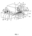
- FIG. 1 is an external appearance view of a first multi-wire saw.
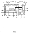
- FIG. 2 is a partial external appearance view of the first multi-wire saw.
- the first multi-wire saw includes a base 1, a frame 2 provided upright on an upper surface of the base 1, a mechanism 4 for supporting a workpiece, which supports a workpiece 3 so that it is movable in a machining direction, a wire supply mechanism 6 for supplying a wire 5 at a cutting portion of the workpiece 3 so that the wire 5 is incorporated into the substance 3, and a slurry supply mechanism 8 for supplying a slurry 7 at a cutting interface between the workpiece 3 and the wire 5.
- the base 1 is composed of a flat board supporting the multi-wire saw.
- the frame 2 is made of a box, and is provided with a side plate 9 opposed to an operator.
- the mechanism 4 for supporting a workpiece includes a stage 11 for fixing the workpiece 3 via a dummy plate 10, a stage moving mechanism 12 supported movably with respect to the frame 2 and adapted to press down the stage 11 while applying a predetermined load to the stage 11 in the machining direction, and a thermostat 13 surrounding the periphery of the stage 11.
- the thermostat 13 includes a machining chamber 16 surrounded by the frame 2, four side walls 14 protruding forward from the frame 2, and a front wall 15 opposed to the frame 2 and connected to a front side of the side walls 14.
- the thermostat 13 further includes an indoor thermometer 17 for measuring the temperature in the machining chamber 16, a heat plate 18 for heating the inside of the machining chamber 16, and a room temperature adjuster 19 for adjusting an electrical power supplied to the heat plate 18 so that the temperature of the machining chamber becomes an optimum temperature for the slurry 7 based on the temperature measured with the indoor thermometer 17, as shown in FIG. 2 .
- the wire supply mechanism 6 includes two motors (not shown) provided to the base 1, an unwinding rotation shaft 20 and a take-up rotation shaft 21 connected respectively to the shafts of the motors, a wire unwinding bobbin 22 which is fitted in the unwinding rotation shaft 20 and from which the wire 5 is unwound, a wire take-up bobbin 23 which is fitted in the take-up rotation shaft 21 and takes up the wire 5 returned from the machining chamber 16, a plurality of guide pulleys 25 for guiding the travel of wire 5 unwound from the wire unwinding bobbin 22 to a main roller 24 supported on the frame 2, a plurality of guide pulleys 26 for guiding the travel of the wire 5 returned from the main roller 24 to the wire take-up bobbin 23, and a tension control roller 43 for controlling the tension of the wire 5 guided with the guide pulleys 25, 26.
- the wire supply mechanism 6 includes a main roller 24 which is rotatably supported so as to be vertical to the frame 2, and in which a plurality of grooves are formed at an equal interval on an outer circumferential surface, and a sub-roller 27 which is rotatably supported with respect to the frame 2 so as to be parallel to the main roller 24, and in which a plurality of grooves are formed at an equal interval on an outer circumferential surface. Furthermore, in the wire supply mechanism 6, a bobbin heater 28 as a wire heating mechanism is housed in the wire unwinding bobbin 22.
- a hot water tank or the like can also be used, which is provided in the vicinity of the main roller 24, and which allows the wire 5 to pass through hot water before an infrared heater that can irradiate the wire 5 with an infrared ray or the main roller 24.
- the present invention is not limited thereto, as long as the wire 5 can be heated.
- the slurry supply mechanism 8 includes a storage tank 30 with a heating mechanism for storing the slurry 7 supplied after being adjusted and the slurry 7 collected in a slurry receiving plate 29 in the machining chamber 16 and returned therefrom, and controlling the temperature of the slurry 7 at an appropriate temperature, a pump 31 for sending the slurry 7 from the storage tank 30 with a heating mechanism, a thermal insulating pipe 32 for allowing the slurry 7 sent from the pump 31 to pass therethrough, and to be sent to the machining chamber 16 while being kept at an optimum temperature, and a slurry discharge part 33 for discharging the slurry 7 sent via the thermal insulating pipe 32 toward the wire 5.
- the storage tank 30 with a heating mechanism includes a slurry storage tank 34, a heater 35 for heating a slurry for heating by surrounding the periphery of the slurry storage tank 34, a thermometer 36 for measuring the temperature of the slurry 7 in the slurry storage tank 34, and a temperature adjuster 37 for adjusting the heating condition of the heater 35 for heating a slurry based on the measured temperature of the slurry 7.
- a heating wire is used as the heater 35 for heating a slurry. In place of this, anything such as a throw-in heater, a ribbon heater, or a hot water heater can be used, as long as it can heat the slurry 7.
- the thermal insulating pipe 32 includes a pipe 38 through which the slurry 7 can pass, a heater 39 for reserving the heat of a slurry wound around a side wall surface of the pipe 38, a thermometer 40 protruding into the pipe 38, for measuring the temperature of the slurry 7, and a temperature adjuster 41 for controlling the heat-reserving condition of the heater 39 for reserving the heat of a slurry based on the temperature of the slurry 7 in the pipe 38.
- the heater 39 for reserving the heat a ribbon heater is used. In place of this, hot water may be allowed to flow through an outer tube of a double tube.
- the present invention is not limited as long as the heat of the slurry 7 in the pipe 38 can be reserved.
- a polycrystalline silicon ingot (hereinafter, referred to as an ingot) is used.
- the outer shape thereof is a prism with a side of 150 mm and a length of 25 mm.
- the ingot is fixed onto a base plate 44 made of stainless steel via a dummy 10 made of glass with an adhesive made of epoxy resin or the like, and the base plate 44 is mechanically fixed to the stage 11.
- the wire 5 used herein is formed of a hard steel wire (piano wire), and its thickness is about 0. 06 to 0.25 mm.
- Other wires may be formed of an alloy such as a nickel-chromium alloy or an iron-nickel alloy, metal with a high melting point such as tungsten or molybdenum, or bound polyamide fibers.
- the wire 5 is unwound from the wire unwinding bobbin 22, has its traveling direction changed by being guided for traveling with the guide pulley 25, and is unwound to the frontmost groove of the main roller 24.
- the wire 5 is unwound to the frontmost groove of the sub-roller 27 while being in contact with the frontmost groove of the main roller 24, and is turned around in the counter-clockwise direction halfway around the sub-roller 27 along the frontmost groove of the sub-roller 27.
- the wire 5 is unwound to the second frontmost groove from the front of the main roller 24, and is turned around in the counter-clockwise direction halfway around the main roller 24 along the second frontmost groove of the main roller 24.
- the wire 5 unwound to the back groove of the main roller 24 from the sub-roller 27 is taken up around the wire take-up bobbin 23 while being guided with the guide pulley 26.
- the winding wire pitch of the main roller 24 and the sub-roller 27 is equal to the cutting pitch of an ingot, and the winding number is also determined arbitrarily in accordance with the number of wafers to be cut from an ingot.
- the slurry 7 contains an alkali or a mixed acid, and its component is composed of abrasive grains, a basic material, and a liquid component.
- abrasive grains those which are generally used as a polishing material may be used. Examples thereof include silicon carbide, cerium oxide, diamond, boron nitride, aluminum oxide, zirconium oxide, and silicon dioxide. Furthermore, they can be used alone or in combination of two or more kinds. Compounds that can be used for abrasive grains are commercially available.
- examples of silicon carbide include GC (Trade Name) (Green Silicon Carbide) and C (Trade Name) (Black Silicon Carbide) (produced by Fuj imi Inc.), and examples of aluminum oxide include FO (Trade Name)(Fujimi Optical Emery), A (Regular Fused Alumina), WA (White Fused Alumina), and PWA (Platelet Calcined Alumina)(produced by Fujimi Inc.).
- the average grain diameter of the abrasive grains is not particularly limited, and it is preferably 1 ⁇ m to 60 ⁇ m, more preferably 5 ⁇ m to 20 ⁇ m.
- the content of the abrasive grains is not particularly limited, and it is preferably 20% by mass to 50% by mass with respect to the total mass of the slurry 7.
- a material acting as a base in the slurry 7 may be used as the basic material.
- examples thereof include alkali metal hydroxide such as lithium hydroxide, sodium hydroxide, and potassium hydroxide, and alkali earth hydroxide such as magnesium hydroxide, calcium hydroxide, and barium hydroxide. They can be used alone or in combination of two or more kinds. Among them, alkali metal hydroxide is preferable in terms of the reactivity with a silicon ingot.
- the content of the basic material is in a range of 3.5% by mass to 20% by mass with respect to the total mass of the liquid component of the slurry 7.
- water a known coolant, and a mixture thereof can be used.
- the water used herein preferably contains less impurity.
- the present invention is not limited thereto. Specific examples of the water include pure water, ultrapure water, city water, and industrial water.
- the content of the water is not particularly limited, and is preferably 10% by mass to 75% by mass with respect to the entire mass of the slurry 7.
- the coolant those which are generally used as a cutting assistant mixed solution containing polyethylene glycol, benzotriazole, oleic acid, and the like, such as a humectant, a lubricant, an anticorrosive, and a viscosity modifier, may be used.
- Such a coolant is commercially available, and specific examples thereof include Rikamultinole (Trade Name) (produced by Rikashokai Co., Ltd.) and Lunacoolant (produced by Daichikagaku).
- the content of the coolant is not particularly limited, and is preferably 0% by mass to 50% by mass with respect to the total mass of the slurry 7.
- the slurry 7 with the above-mentioned configuration can be prepared by mixing the respective components in a desired ratio.
- the method of mixing the respective components is arbitrary, and for example, the components can be mixed by stirring with a wing-type stirrer.
- the order of mixing the respective components is also arbitrary.
- the prepared slurry 7 may be subject to further processing (e.g., filtering and ion exchange processing).
- the slurry 7 has a strong basicity. Therefore, the cutting interface of a silicon ingot weakens due to the reaction as represented by the following formula (1), and lapped with abrasive grains. Si + 4H 2 O ⁇ Si(OH) 4 + 2H 2 (1)
- the temperature of the slurry 7 for promoting the chemical reaction between the slurry 7 and the ingot is preferably in a range of 65°C to 95°C. In the case where the temperature of the slurry 7 is too low, the reaction is not activated, so that the cutting resistance is not reduced sufficiently.
- the extremely high temperature of the slurry 7 is not preferable because water required for the reaction becomes insufficient due to the evaporation of the liquid component (mainly water) in the slurry, with the result that the cutting resistance increases.
- the slurry 7 thus prepared is stored in the slurry storage tank 34, and heated to 65°C to 95°.
- the slurry 7 with the temperature thus adjusted is discharged from the slurry discharge part 33 while the temperature of the slurry 7 is being kept at 65°C to 95°C in the thermal insulating pipe 32.
- the slurry 7 adheres to the wire 5 positioned below the slurry discharge part 33, and introduced to the cutting interface between the ingot and the wire 5.
- the ingot pressed down by the workpiece supporting mechanism 4 and the wire 5 with a slurry are brought into contact with each other, pressed, and slide, whereby an ingot is machined.
- the temperature of the air in the machining chamber 16 is controlled to be 65°C to 95°C.
- the wire 5 is also heated to 65°C to 95°C.
- an optimum temperature of the slurry 7, e.g. , 80°C the respective temperatures of the slurry 7, the wire 5, and the machining chamber 16 are controlled to be 80°C.
- a composition of the slurry 7 4 parts by mass of sodium hydroxide were dissolved in 46 parts by mass of water to obtain a basic aqueous solution, and this aqueous solution and 50 parts by mass of a coolant (Lunacoolant #691, produced by Daichikagaku) were mixed. To this mixed solution, 100 parts by mass of SiC abrasive grains (GC#1200, average grain diameter: about 10 ⁇ m, produced by Fujimi Inc.) were added, followed by stirring, whereby a slurry 7 was prepared. The pH of the obtained slurry 7 at 25°C was 13.9.
- a polycrystalline silicon ingot (side: 150 mm, length: 25 mm) was cut under the following cutting conditions to produce a wafer.
- the cutting conditions were a wire diameter of 0.1 mm, a cutting allowance of 0.13 mm, a cutting pitch of 0.39 mm, a cutting speed of 0.35 mm/min. , a wire traveling speed of 600 m/min., and a slurry temperature of 80°C.
- an ingot was cut similarly at a slurry temperature of 25°C.
- an index representing the magnitude of the cutting resistance a warpage amount of the wire 5 was measured. Table 1 shows the results.
- Embodiment 1 cutting machining can be performed while the temperatures of the slurry and the workpiece are maintained at desired values. Therefore, high wafer quality with small thickness irregularity and a very small amount of saw marks can be maintained, and the wire warpage amount, i.e., the cutting resistance can be reduced remarkably.
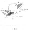
- FIG. 4 is an external appearance view of a wire heating mechanism of a second multi-wire saw of the present invention.
- the second multi-wire saw is the same as the first multi-wire saw except for the wire heating mechanism, so that the description of the same parts will be omitted.
- the wire heating mechanism includes two pulleys 25a, 25b that are away from each other so that the wire 5 with a desired length can travel, among a plurality of guide pulleys 25 for guiding the wire 5 between the wire unwinding bobbin 22 to the main roller 24, and a power source 42 for supplying a voltage between the two pulleys 25a, 25b.
- the pulleys 25a, 25b have conductivity, and a portion between the pulleys 25a, 25b, and the wire 5 can be brought into conduction.
- the wire unwinding bobbin 22 and the wire take-up bobbin 23 have insulation property so as to electrically float the wire 5.
- the wire heating mechanism can heat the wire 5 by allowing a current to flow through the wire 5 between the pulleys 25a, 25b to generate Joule heat
- a time t(sec) required for a minute portion ⁇ x of the wire 5 to pass between the pulleys can be obtained from the following formula (2).
- a mass W(g) of the wire 5 present between the pulleys can be obtained from the following formula (3), assuming that a wire specific gravity A is 7.8(g/cm 2 ).
- a heat amount Q(J) required for raising the temperature can be obtained from the following formula (4), assuming that a wire specific heat C is 0.5(J/gK).
- a current amount I (A) flowing through the wire 5 at this time can be obtained from the required heat amount Q from the following formula (5).
- a A voltage V (V) between the pulleys that must be applied between the pulleys is as represented by the following formula (6).
- the wire can be heated easily with a commercially available general-purpose voltage source and battery. Furthermore, the heating temperature of the wire can be controlled easily by varying a power source voltage.
- FIG. 4 is an external appearance view of a third multi-wire saw.
- FIG. 5 is a partial external appearance view of the third multi-wire saw.
- FIG. 6 is a view illustrating a cutting process of a workpiece with the third multi-wire saw.
- the third multi-wire saw includes a base 1, a frame 2 provided upright on an upper surface of the base 1, a workpiece supporting mechanism 4, which supports a workpiece 3 so that it is movable in a machining direction, a wire supply mechanism 6 for supplying a wire 5 at a cutting portion of the workpiece 3 so that the wire 5 is incorporated into the substance 3, and a slurry supply mechanism 8A for supplying a slurry 7 at a cutting interface between the workpiece 3 and the wire 5.
- the base 1 is composed of a flat board supporting the multi-wire saw.
- the frame 2 is made of a box, and is provided with a side plate 9 opposed to an operator.
- the workpiece supporting mechanism 4 includes a stage 11 for fixing the workpiece 3 via a dummy plate 10, a stage moving mechanism 12 supported movably with respect to the frame 2 and adapted to press down the stage 11 while applying a predetermined load to the stage 11 in the machining direction, and a machining chamber 16 surrounding the periphery of the stage 11.
- the machining chamber 16 is surrounded by the frame 2, four side walls 14 protruding forward from the frame 2, and a front wall 15 opposed to the frame 2 and connected to a front side of the side walls 14. As shown in FIG.
- a discharge portion 45 for discharging atmosphere (containing gas generated during cutting machining, e.g., hydrogen) in the machining chamber 16 is provided, and a slurry collection drain tube 46 is connected to a slurry receiving plate 29 of the machining chamber 16.
- a humidity adjusting mechanism 47 for adjusting the humidity in the machining chamber 16 to be a set humidity is attached.
- the humidity adjustingmechanism 47 includes a humidifier 49 for gene rat ing water vapor 48, a hygrometer 50 for measuring humidity, and a control device 51 for operating/suspending the humidifier 49 based on the comparison results between the set humidity and the measured humidity in the machining chamber 16.
- the humidity in the machining chamber 16 can be adjusted by the humidity adjusting mechanism 47.
- the humidifier 49 used herein is not particularly limited, as long as it can generate the water vapor 48.
- Examples of the humidifier 49 include an ultrasonic humidifier and a heater-type humidifier.
- the wire supply mechanism 6 includes two motors (not shown) provided to the base 1, an unwinding rotation shaft 20 and a take-up rotation shaft 21 connected respectively to the shafts of the motors, a wire unwinding bobbin 22 which is fitted in the unwinding rotation shaft 20 and from which the wire 5 is unwound, a wire take-up bobbin 23 which is fitted in the take-up rotation shaft 21 and takes up the wire 5 returned from the machining chamber 16, a plurality of guide pulleys 25 for guiding the travel of wire 5 unwound from the wire unwinding bobbin 22 to a main roller 24 supported on the frame 2, a plurality of guide pulleys 26 for guiding the travel of the wire 5 returned from the main roller 24 to the wire take-up bobbin 23, and a tension control roller 43 for controlling the tension of the wire 5 guided with the guide pulleys 25, 26.
- the wire supply mechanism 6 includes a main roller 24 which is rotatably supported so as to be vertical to the frame 2, and in which a plurality of grooves are formed at an equal interval on an outer circumferential surface, and a sub-roller 27 which is rotatably supported with respect to the frame 2 so as to be parallel to the main roller 24, and in which a plurality of grooves are formed at an equal interval on an outer circumferential surface.
- the slurry supply mechanism 8A includes: a slurry storage tank 34 for storing the slurry 7 supplied to the wire 5, and the slurry 7 collected in the slurry receiving plate 29 in the machining chamber 16 and returned therefrom via the slurry collection drain tube 46; a pump 31 for sending the slurry 7 from the slurry storage tank 34; a pipe 32A for allowing the slurry 7 sent from the pump 31 to pass therethrough to be sent to the machining chamber 16; and a slurry discharge part 33 for discharging the slurry 7 sent via the pipe 32A toward the wire 5.
- the slurry discharge part 33 is placed above the position between the sub-roller 27 placed on a upstream side of a site where the workpiece 3 is cut and the site where the workpiece 3 is cut in the machining chamber 16.
- the slurry storage tank 34 may be placed in the machining chamber 16, it is desirably placed outside of the machining chamber 16 because the slurry storage amount is limited, and the structure of the machining chamber 16 becomes complicated when the slurry storage tank 34 is placed in the machining chamber 16.
- a polycrystalline silicon ingot (hereinafter, referred to as an ingot) is used.
- the ingot is fixed onto a base plate 44 made of stainless steel via a dummy 10 made of glass with an adhesive made of epoxy resin or the like, and the base plate 44 is mechanically fixed to the stage 11.
- the wire 5 is wound between the main roller 24 and the sub-roller 27 in a spiral shape.
- the wire 5 used herein is formed of a hard steel wire (piano wire), and its thickness is about 0. 06 to 0.25 mm.
- Other wires may be formed of an alloy such as a nickel-chromium alloy or an iron-nickel alloy, metal with a high melting point such as tungsten or molybdenum, or bound polyamide fibers.
- the wire 5 is unwound from the wire unwinding bobbin 22, has its traveling direction changed by being guided for traveling with the guide pulley 25, and is unwound to the frontmost groove of the main roller 24.
- the wire 5 is unwound to the frontmost groove of the sub-roller 27 while being in contact with the frontmost groove of the main roller 24, and is turned around in the counter-clockwise direction halfway around the sub-roller 27 along the frontmost groove of the sub-roller 27.
- the wire 5 is unwound to the second frontmost groove of the main roller 24, and turned around in the counter-clockwise direction halfway around the main roller 24 along the second frontmost groove of the main roller 24.
- the wire 5 unwound to the back groove of the main roller 24 from the sub-roller 27 is taken up around the wire take-up bobbin 23 while being guided with the guide pulley 26.
- the winding wire pitch of the main roller 24 and the sub-roller 27 is equal to the cutting pitch of an ingot, and the winding number is also determined arbitrarily in accordance with the number of wafers to be cut from an ingot.
- the wire supply mechanism 6 When the wire supply mechanism 6 is driven in such a multi-wire saw, the wire 5 travels in a fixed direction at a predetermined speed while a constant tension is being maintained by the tension control roller 43. At this time, the main roller 24 and the sub-roller 27 are rotated in synchronization at a rotation speed in accordance with the traveling speed of the wire 5. In the machining chamber 16, the wire 5 is guided along the grooves of the main roller 24 and the sub-roller 27. Therefore, the wire 5 is arranged at a constant tension while the lines of the wire 5 travel in parallel below the stage 11.
- the workpiece supporting mechanism 4 presses down an ingot as the workpiece 3 toward the wire 5
- the ingot comes into contact with the traveling wire 5 and is pressed against it.
- the water vapor 48 is re leased from the humidity ad jus ting mechanism 47 to the machining chamber 16, whereby the humidity (relative humidity) in the machining chamber 16 is kept in a state close to a saturated vapor pressure.
- the humidity adjustment in the machining chamber 16 by the humidity adjusting mechanism 47 will be described with reference to FIG. 7 .
- Step 101 when it is confirmed that the multi-wire saw is being operated, the set humidity input to the control device 51 is read in Step 101, and the process proceeds to Step 102.
- Step 102 the humidity in the machining chamber 16 measured by the hygrometer 50 is read, and the process proceeds to Step 103.
- Step 103 the control device 51 determines whether or not the measured humidity in the machining chamber 16 is in the set range. In the case where the measured humidity in the machining chamber 16 is lower than the set range, the determination is denied, and the process proceeds to Step 104, whereby humidification is started by the humidifier 49. On the other hand, in Step 103, in the case where the measured humidity in the machining chamber 16 is higher than the set range, the determination is affirmed, and the process proceeds to Step 105, where humidification by the humidifier 49 is stopped.
- the humidity in the machining chamber 16 be adjusted to be in a range of 95 to 99%.
- the humidity is too low, the evaporation amount of water contained in the slurry 7 increases, and the viscosity of the slurry 7 increases, so that saw marks may be generated.
- the humidity is too high, the water vapor 48 released to the machining chamber 16 becomes water droplets, which are collected in the slurry receiving plate 29, whereby the slurry 7 in the slurry storage tank 34 is diluted to decrease the viscosity.
- the viscosity of the slurry 7 decreases, the amount of the slurry 7 that drops from the wire 5 increases, and the cutting efficiency may decrease.
- FIG. 8 shows the results.
- a rotation viscometer e.g., Programmable rheometer DV-III, produced by Brookfield.
- the humidity in the machining chamber 16 is maintained in a state close to a saturated vapor pressure, so that the change in viscosity of the slurry 7 is very small, and the slurry 7 is not dried or solidified in an inlet portion through which the wire 5 is inserted to a silicon ingot as the workpiece 3. Therefore, the breakage of the wire can be prevented while high machining quality is maintained. Furthermore, a mechanism for adjusting the viscosity while supplying water to the slurry storage tank 34 as in the conventional multi-wire saw is not required, which makes it easy to manage the viscosity of the slurry.
- the slurry discharge part 33 is placed above a position between the sub-roller 27 placed on an upstream side of a site where the workpiece 3 is cut and the site where the workpiece 3 is cut, the present invention is not limited thereto.
- the slurry discharge part 33 may be placed so as to be close to an upstream side wall surface of a site where the workpiece 3 is cut so that the slurry 7 discharged from the slurry discharge part 33 moves along a side surface of the workpiece 3 and supplied to the wire 5.
- the humidity adjusting mechanism 47 is placed in the machining chamber 16.
- the present invention is not limited thereto as long as the water vapor 48 can be released from the humidity adjusting mechanism 47 to the machining chamber 16.
- the humidity adjusting mechanism 47 may be placed outside of the machining chamber 16 so that the water vapor 48 is released from the humidity adjusting mechanism 47 to the machining chamber 16 via a piping or the like.
- a forced convection type fan may be provided so that the humidity in the machining chamber 16 becomes uniform.
- a heater for heating a slurry that surrounds the periphery of the slurry storage tank 34 and heats it may be provided.
- a heater for heating a slurry there is no particular limit as long as it can heat the slurry 7.
- Examples of the heater for heating a slurry include a heating wire, a throw-in heater, a ribbon heater, and a hot water heater.
- FIG. 9 is an external appearance view of a fourth multi-wire saw .
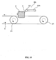
- FIG. 10 is a partial external appearance view of the multi-wire saw of Embodiment 4.
- FIG. 11 illustrates a cutting process of a workpiece by the fourth multi-wire saw.
- the fourth multi-wire saw includes a base 1, a frame 2 provided upright on an upper surface of the base 1, a workpiece supporting mechanism 4, which supports a workpiece 3 so as to be movable in a machining direction, a wire supply mechanism 6 for supplying a wire 5 to a cutting portion of the workpiece 3 so that the wire 5 is incorporated into the substance 3, and a slurry supply mechanism 8B for supplying a slurry 7 to a cutting interface between the workpiece 3 and the wire 5.
- the base 1 is composed of a flat board supporting the multi-wire saw.
- the frame 2 is made of a box, and is provided with a side plate 9 opposed to an operator.
- the workpiece supporting mechanism 4 includes a stage 11 for fixing the workpiece 3 via a dummy plate 10, a stage moving mechanism 12 supported movably with respect to the frame 2 and adapted to press down the stage 11 in the machining direction, and a machining chamber 16 surrounding the periphery of the stage 11.
- the machining chamber 16 is surrounded by the frame 2, four side walls 14 protruding forward from the frame 2, and a front wall 15 opposed to the frame 2 and connected to a front side of the side walls 14.
- the wire supply mechanism 6 includes two motors (not shown) provided to the base 1, an unwinding rotation shaft 20 and a take-up rotation shaft 21 connected respectively to the shafts of the motors, a wire unwinding bobbin 22 which is fitted in the unwinding rotation shaft 20 and from which the wire 5 is unwound, a wire take-up bobbin 23 which is fitted in the take-up rotation shaft 21 and takes up the wire 5 returned from the machining chamber 16, a plurality of guide pulleys 25 for guiding the travel of wire 5 unwound from the wire unwinding bobbin 22 to a main roller 24 supported on the frame 2, a plurality of guide pulleys 26 for guiding the travel of the wire 5 from the main roller 24 to the wire take-up bobbin 23, and a tension control roller 43 for controlling the tension of the wire 5 guided with the guide pulleys 25, 26.
- the wire supply mechanism 6 includes the main roller 24 which is rotatably supported so as to be vertical to the frame 2, and in which a plurality of grooves are formed at an equal interval on an outer circumferential surface, and a sub-roller 27 which is rotatably supported with respect to the frame 2 so as to be parallel to the main roller 24, and in which a plurality of grooves are formed at an equal interval on an outer circumferential surface.
- the slurry supply mechanism 8B includes a slurry storage tank 34 for storing a slurry 7 supplied to the wire 5 and a slurry 7 collected by a slurry receiving plate 29 in the machining chamber 16 and returned via the slurry collection drain tube 46, a pump 31 for sending the slurry 7 from the slurry storage tank 34, a pipe 32A through which the slurry 7 sent from the pump 31 is sent to the machining chamber 16, and a slurry discharge part 33 for discharging the slurry 7 sent via the pipe 32A to the wire 5. As shown in FIG.
- the slurry discharge part 33 is provided above a position between the sub-roller 27 provided on an upstream side of a site where the workpiece 3 is cut and the site where the workpiece 3 is cut so that the discharged slurry 7 moves along a side surface of the workpiece 3 (the slurry 7 is positioned close to an upstream side wall surface of the site where the workpiece 3 is cut).
- the slurry 7 is supplied from the slurry discharge part 33 to the wire 5
- the slurry 7 is discharged, for example, in a curtain shape, from the slurry discharge part 33.
- the slurry discharge part 33 is placed above the site where the workpiece 3 is cut, so that the discharge slurry 7 flows down along the side surface of the workpiece 3.
- the slurry 7 moves to a crossing point between the wire 5 and the workpiece 3 without undergoing evaporation of water to come into contact with the wire 5, the slurry 7 is transported to the cutting interface of the workpiece 3 by the wire 5.
- the slurry 7 always flows on the side surface of the workpiece 3, in particular, at a crossing point between the running wire 5 and the workpiece 3, so that the viscosity of the slurry 7 always becomes constant.
- a polycrystalline silicon ingot (hereinafter, referred to as an ingot) is used.
- the ingot is fixed onto a base plate 44 made of stainless steel via a dummy 10 made of glass with an adhesive made of epoxy resin or the like, and the base plate 44 is mechanically fixed to the stage 11.
- the wire 5 is wound between the main roller 24 and the sub-roller 27 in a spiral shape.
- the wire 5 used herein is formed of a hard steel wire (piano wire), and its thickness is about 0.06 to 0.25 mm.
- Other wires may be formed of an alloy such as a nickel-chromium alloy or an iron-nickel alloy, metal with a high melting point such as tungsten or molybdenum, or bound polyamide fibers.
- the wire 5 is unwound from the wire unwinding bobbin 22, has its traveling direction changed by being guided for traveling with the guide pulley 25, and is unwound to the frontmost groove of the main roller 24.
- the wire 5 is unwound to the frontmost groove of the sub-roller 27 while being in contact with the frontmost groove of the main roller 24, and is turned around in the counter-clockwise direction halfway around the sub-roller 27 along the frontmost groove of the sub-roller 27.
- the wire 5 is unwound to the second frontmost groove of the main roller 24, and turned around in the counter-clockwise direction halfway around the main roller 24 along the second frontmost groove of the main roller 24.
- the wire 5 unwound to the rearmost groove of the main roller 24 from the sub-roller 27 is taken up around the wire take-up bobbin 23 while being guided with the guide pulley 26.
- the winding wire pitch of the main roller 24 and the sub-roller 27 is equal to the cutting pitch of an ingot, and the winding number is also determined arbitrarily in accordance with the number of wafers to be cut from an ingot.
- the wire supply mechanism 6 When the wire supply mechanism 6 is driven in such a multi-wire saw, the wire 5 travels in a fixed direction at a predetermined speed while a constant tension is being maintained by the tension control roller 43. At this time, the main roller 24 and the sub-roller 27 are rotated in synchronization with each other at a rotation speed in accordance with the traveling speed of the wire 5. In the machining chamber 16, the wire 5 is guided along the grooves of the main roller 24 and the sub-roller 27. Therefore, the wire 5 is arranged under a constant tension while the lines of the wire 5 travel in parallel below the stage 11.
- the workpiece supporting mechanism 4 presses down an ingot as the workpiece 3 toward the wire 5
- the ingot comes into contact with the traveling wire 5 and is pressed against it.
- a silicon ingot (side: 150 mm, length: 25 mm) was cut under the condition that the cutting speed was 0.35 mm/min., and the wire traveling speed was 600 m/min. , using a slurry at 80°C containing 4% by mass of sodium hydroxide and a piano wire with a diameter of 0.1 mm in the fourth multi-wire saw (the wire was not broken). After cutting, the inlet portion through which the wire is inserted to the silicon ingot was observed. As a result, the adhesion of a solidified slurry was not recognized. When a silicon ingot was cut using a conventional multi-wire saw, and a wire was broken about one hour (cutting length: about 21 mm) after the commencement of cutting machining, a large amount of solidified slurry adhered to the inlet portion.
- the slurry 7 always flows at a crossing point between the running wire 5 and an ingot as the workpiece 3, so that the slurry 7 is not dried or solidified. Therefore, the resistance applied upon the running of the wire 5 can be reduced, and the breakage of the wire that markedly decreases the productivity can be prevented.
- FIG. 12 is a partial external appearance view of a fifth multi-wire saw.
- the slurry supply mechanism 8C includes a sheet component 52 attached to a side surface of the workpiece 3. Otherwise, the fifth wire saw is configured in the same way as the fourth wire saw.
- the sheet component 52 used herein may be made of a material that does not react with the slurry 7 or has a very low reactivity with respect to the slurry 7.
- a material for the slurry 7 containing a strong alkaline substance such as sodium hydroxide include polyethylene, polypropylene, methylpentene resin, fluorine resin, natural rubber, styrene rubber, butyl rubber, and ethylene ⁇ propylene rubber.
- the sheet component 52 preferably has a hardness smaller than that of the workpiece 3 from the viewpoint of the cutting efficiency.
- the temperature of the cutting site of the workpiece 3 often increases to a high temperature of about 100°C due to the resistance applied during traveling of the wire 5. Therefore, when the sheet component 52 made of the above-mentioned material is attached, it is preferable to use a thermoplastic adhesive with a glass transition temperature of 100°C or higher.
- the sheet component 52 is attached to a side surface of the workpiece 3. Therefore, the slurry 7 discharged from the slurry discharge part 33 flows down along the surface of the sheet component 52. Consequently, even when the slurry 7 having a chemical reactivity with respect to the workpiece 3 continues to be discharged to the side surface of the workpiece 3, the surface of the workpiece 3 is not etched.
- the side surface of the workpiece 3 is not etched, and the change in size of the workpiece 3 can be minimized.
- the slurry discharge part 33 is placed above a position between the sub-roller 27 and the site where the workpiece 3 is cut.
- the slurry discharge part 33 may not be placed above such a position, as long as the discharged slurry 7 can move along the side surface of the workpiece 3 and come into contact with the wire 5.
- the slurry discharge part 33 may be placed by the side of or below a position between the sub-roller 27 and the site where the workpiece 3 is cut, so that the slurry 7 is discharged to the side surface of the workpiece 3.
- a water control mechanism for keeping the water amount in the slurry 7 constant may be provided so that the composition of the slurry 7 discharged from the slurry discharge part 33 becomes constant.
- the composition changes due to the evaporation of water, so that it is desirable to provide a water control mechanism.
- the configuration for moving the slurry 7 along the side surface of the workpiece 3 to the slurry 7 and the configuration for directly coating the wire 5 with the slurry 7 to supply the slurry 7 may be combined to introduce the slurry 7 to the cutting interface of the workpiece 3.
- the slurry 7 supplied by being directly applied to the wire 5 is mainly used for cutting the workpiece 3, and the slurry 7 moving along the side surface of the workpiece 3 is used as auxiliary means for preventing the solidification of the slurry 7 in the inlet portion through which the wire 5 is inserted into the workpiece 3. Therefore, it is preferable that the flow rate of the slurry 7 moving along the side surface of the workpiece 3 be set to the minimum.
- FIG. 13 is an external appearance view of a sixth multi-wire saw .
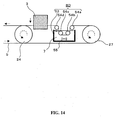
- FIG. 14 is a partial external appearance view of the sixth multi-wire saw.
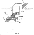
- FIG. 15 illustrates a cutting process of a workpiece with the sixth multi-wire saw.
- the sixth multi-wire saw includes a base 1, a frame 2 provided upright on an upper surface of the base 1, a workpiece supporting mechanism 4, which supports a workpiece 3 so as to be movable in the machining direction, a wire supply mechanism 6 for supplying a wire 5 to a cutting portion of the workpiece 3 so that the wire 5 is incorporated into the substance 3, and a slurry supply mechanism 8 for supplying a slurry 7 to a cutting interface between the workpiece 3 and the wire 5.
- the base 1 is composed of a flat board supporting the multi-wire saw.
- the frame 2 is made of a box, and is provided with a side plate 9 opposed to an operator.
- the workpiece supporting mechanism 4 includes a stage 11 for fixing the workpiece 3 via a dummy plate 10, a stage moving mechanism 12 supported movably with respect to the frame 2 and adapted to press down the stage 11 while applying a predetermined load to the stage 11 in the machining direction, and a machining chamber 16 surrounding the periphery of the stage 11.
- the machining chamber 16 is surrounded by the frame 2, four side walls 14 protruding forward from the frame 2, and a front wall 15 opposed to the frame 2 and connected to a front side of the side walls 14.
- the wire supply mechanism 6 includes two motors (not shown) provided to the base 1, an unwinding rotation shaft 20 and a take-up rotation shaft 21 connected respectively to the shafts of the motors, a wire unwinding bobbin 22 which is fitted in the unwinding rotation shaft 20 and from which the wire 5 is unwound, a wire take-up bobbin 23 which is fitted in the take-up rotation shaft 21 and takes up the wire 5 returned from the machining chamber 16, a plurality of guide pulleys 25 for guiding the travel of wire 5 unwound from the wire unwinding bobbin 22 to a main roller 24 supported on the frame 2, a plurality of guide pulleys 26 for guiding the travel of the wire 5 from the main roller 24 to the wire take-up bobbin 23, and a tension control roller 43 for controlling the tension of the wire 5 guided with the guide pulleys 25, 26.
- the wire supply mechanism 6 includes the main roller 24 which is rotatably supported so as to be vertical to the frame 2, and in which a plurality of grooves are formed at an equal interval on an outer circumferential surface, and a sub-roller 27 which is rotatably supported with respect to the frame 2 so as to be parallel to the main roller 24, and in which a plurality of grooves are formed at an equal interval on an outer circumferential surface.
- the slurry supply mechanism 8D includes a liquid tank 53 as an storing portion for storing the slurry 7, and a plurality of wire guiding rollers 54a, 54b, 54c, and 54d for introducing the wire 5 into the liquid tank 53 and pulling up the wire 5 from the liquid tank 53 to guide it to the workpiece 3. Furthermore, the liquid tank 53 is placed at a position between the sub-roller 27 positioned on an upstream side of a cutting portion of the workpiece 3 and the cutting portion of the workpiece 3, and has a stirring mechanism 55 for stirring the slurry 7 on a bottom portion.
- a polycrystalline silicon ingot (hereinafter, referred to as an ingot) is used.
- the ingot is fixed onto a base plate 44 made of stainless steel via a dummy 10 made of glass with an adhesive made of epoxy resin or the like, and the base plate 44 is mechanically fixed to the stage 11.
- the wire supply mechanism 6 is driven, the wire 5 travels in a fixed direction at a predetermined speed while a constant tension is being maintained by the tension control roller 43.
- the main roller 24 and the sub-roller 27 are rotated in synchronization with each other at a rotation speed in accordance with the traveling speed of the wire 5.
- the wire 5 traveling between the main roller 24 and the sub-roller 27 enters the liquid tank 53 via the wire guiding roller 54a, is successively guided by the wire guiding rollers 54b, 54c, and sent out of the liquid tank 53. Since the slurry 7 is held in the liquid tank 53, the slurry 7 is supplied to the wire 5 as the wire 5 is guided in the liquid tank 53. Then, the slurry 7 adhering to the wire 5 is transported to the cutting interface of an ingot by the travel of the wire 5. Then, the bond of silicon atoms is broken by the lapping action and the chemical action of the slurry 7, whereby an ingot is cut.
- a slurry storage/stirring tank for collecting the amount of the slurry 7 introduced to the cutting interface of the ingot, and a mechanism for supplying the amount of the slurry 7 introduced to the cutting interface of the ingot from the slurry storage/stirring tank to the liquid tank 53 are provided.
- the wire 5 is designed so as to pass through the liquid tank 53 placed on an upstream side of the cutting portion of the workpiece 3. Therefore, an appropriate amount of the slurry 7 adheres to the wire 5 sent from the liquid tank 53, which can cut the waste of the slurry, enhance the utilization efficiency of the slurry, and suppress an increase in the production cost. Furthermore, a slurry supply mechanism with a large flow rate and a large power for supplying/circulating a large amount of the slurry 7 is not required, resulting in an inexpensive apparatus. Furthermore, since the wire 5, to which an appropriate amount of the slurry 7 adheres, travels in the machining chamber 16, so that the scattering of the slurry 7 can also be minimized.
- the liquid tank 53 of the sixth wire saw may have a capacity smaller than that of the conventional one, so that the temperature of the slurry 7 can be managed easily, and the amount of the circulating slurry can be minimized. Therefore, the composition of the slurry in the slurry storage/stirring tank is stabilized, and the uniform dispersibility of abrasive grains can be maintained.
- the composition of the slurry is managed precisely, and the slurry 7 in a state close to that adjusted initially can be continued to be supplied to the cutting interface of the workpiece 3, which suppresses the variation in wafer thickness, the generation of saw marks (scars), and the like, and improves the machining quality. Furthermore, the amount of the slurry 7 adhering to the opposed portion of the wire 5 wound in a spiral shape decreases, so that the slurry 7 does not adhere in an excess amount to the sub-roller 27 on a side close to the liquid tank 53, which can suppress the shortening of the life due to the abrasion of a roller groove.
- liquid tank 53 a temperature control mechanism (not shown) for keeping the temperature constant as required, a filter (not shown) for removing cuttings of the workpiece 3, and the like may be provided.
- the liquid tank 53 is preferably placed close to the cutting portion of the workpiece 3.
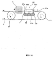
- FIG. 16 is a partial external appearance view of a multi-wire saw of the first embodiment of the invention
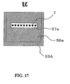
- FIG. 17 is a view taken along an arrow X of FIG. 16
- the multi-wire saw of the first embodiment is the same as that of the sixth multi-wire saw except for the slurry supply mechanism, so that the description of the same portions will be omitted.
- the slurry supply mechanism 8E is provided with a liquid tank 53A with a stirring mechanism 55 for holding a slurry 7, and two opposing side wall portions 56a, 56b, from among side surface portions as the surfaces constituting the liquid tank 53A are provided with slit-shaped passage holes 57a, 57b, respectively.
- the passage holes 57a, 57b are positioned below the liquid level of the slurry 7 when the slurry 7 is held in the liquid tank 53A. Further, as shown in FIG. 17 , lines of the wire 7 passed over the main roller 24 and the sub-roller 27 are placed so as to pass through the slit-shaped passage holes 57a, 57b. Therefore, the lines of the wire 7 are guided in the slurry 7 while passing through the liquid tank 53A.
- the wire 5 enters the liquid tank 53A through one passage hole 57a. At this time, the slurry 7 is held in the liquid tank 53A. Therefore, the wire 5 comes into contact with the slurry 7 to supply the slurry 7 to the wire 5.
- the wire 5, to which the slurry 7 adheres to, is sent out of the liquid tank 53A from the passage hole 57b of the opposed side wall portion 56b, and the slurry 7 is transported to the cutting interface of the workpiece 3 owing to the travel of the wire 5.
- a slight gap is formed between the passage hole 57a and the wire 5, and the slurry 5 leaks therefrom.
- a collecting tray 58 be provided in a lower portion of the liquid tank 53A.
- the wire 5 does not travel on the wire guiding rollers 54a, 54b, 54c, and 54d. Therefore, the utilization efficiency of the slurry can be enhanced further. Furthermore, the requisite wire stretching operation is reduced, which enhances the workability.
- the liquid tank 53A may be provided with the stirring mechanism 55, the temperature control mechanism (not shown) for keeping the temperature constant, and the filter (not shown) for removing the cuttings of an ingot.
- the passage holes 57a, 57b are provided on the opposed side surface portions 56a, 56b in the slurry supply mechanism 8E.
- the present invention is not limited thereto, and they may be provided on any side surface portion, as long as the wire 5 can be guided with respect to the slurry 7 in the liquid tank 53A.
- a construction may be employed in which the cutting position of the workpiece 3 is placed above the liquid tank 53A, and a roller for changing the direction is provided in the liquid tank 53A, whereby the wire 5 is guided above the liquid tank 53A after entering from the side wall portion 56a.
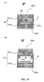
- FIG. 18 illustrates a side wall portion in a slurry supply mechanism 8F of the multi-wire saw according to the second embodiment .
- FIG. 18(A) is a view illustrating a closed state
- FIG. 18(B) is a view illustrating an open state.
- a side wall portion 56c of the liquid tank 53A and a side wall portion (not shown) opposed thereto include an openable member 60 with a cutout portion 59.
- the openable member 60 is composed of an upper side wall member 61a provided with the cutout portion 59 and a lower side wall member 61b fixed to the liquid tank 53A.
- the cutout portion 59 forms a passage hole 57c, as shown in FIG. 18(A) .
- the slurry supply mechanism 8F during a preparation operation of winding the wire 5 around the main roller 24 and the sub-roller 25 in a spiral shape, it is not necessary to pass the wire 5 through the passage hole 57c for every turn of the wire 5, which enhances the workability. More specifically, during a preparation operation of winding the wire 5, as shown in FIG. 5(B) , the upper side wall member 61a only needs to be detached to allow the wire 5 to pass through the cutout portion 59. During cutting of the workpiece 3, the following only needs to be performed. That is, the upper side wall member 61a is closed again, forming the passage hole 57c, the slurry 7 is supplied to the liquid tank 53A, and thereafter, the workpiece 3 is cut as described in Embodiment 7.
- the leakage of the slurry 7 can be sealed sufficiently only with mechanical fastening.
Landscapes
- Engineering & Computer Science (AREA)
- Mechanical Engineering (AREA)
- Processing Of Stones Or Stones Resemblance Materials (AREA)
- Finish Polishing, Edge Sharpening, And Grinding By Specific Grinding Devices (AREA)
- Grinding-Machine Dressing And Accessory Apparatuses (AREA)
- Mechanical Treatment Of Semiconductor (AREA)
Claims (2)
- Scie à fils multiples pour découper une pièce d'ouvrage (3) tout en fournissant une bouillie (7) contenant des grains abrasifs à un fil (5) se déplaçant entre une pluralité de rouleaux (24, 27),
dans laquelle un mécanisme de fourniture de bouillie (8E, 8F) comportant une partie de retenue (53, 53A) pour retenir la bouillie (7) et un mécanisme de régulation de température pour maintenir la température de la bouillie (7) constante et apte à fournir la bouillie (7) au fil (5) alors que le fil (5) passe à travers la partie de retenue (53, 53A) sont disposés à une position où la pièce d'ouvrage (3) est découpée ;
et dans laquelle une surface (56a, 56b, 56c) constituant la partie de retenue (53, 53A) est fournie avec un passage (57a, 57b, 57c) permettant au fil (5) de passer à travers celui-ci,
caractérisée en ce que le mécanisme de fourniture de bouillie (8E, 8F) est fourni à une position où la pièce d'ouvrage (3) est découpée, et en ce que le passage comprend un trou de passage (57a, 57b, 57c). - Scie à fils multiples selon la revendication 1,
caractérisée en ce que la surface (56a, 56b, 56c) constituant la partie de retenue (53A) comporte un organe ouvrable (60) pourvu d'une partie de découpe (59),
et en ce que, lorsque l'organe (60) est fermé, la partie de découpe (59) forme le trou de passage (57a, 57b, 57c).
Applications Claiming Priority (5)
| Application Number | Priority Date | Filing Date | Title |
|---|---|---|---|
| JP2003366378 | 2003-10-27 | ||
| JP2003365719 | 2003-10-27 | ||
| JP2003369476 | 2003-10-29 | ||
| JP2003370859 | 2003-10-30 | ||
| EP04792847.8A EP1685927B1 (fr) | 2003-10-27 | 2004-10-22 | Scie multicable |
Related Parent Applications (2)
| Application Number | Title | Priority Date | Filing Date |
|---|---|---|---|
| EP04792847.8 Division | 2004-10-22 | ||
| EP04792847.8A Division EP1685927B1 (fr) | 2003-10-27 | 2004-10-22 | Scie multicable |
Publications (2)
| Publication Number | Publication Date |
|---|---|
| EP2343155A1 EP2343155A1 (fr) | 2011-07-13 |
| EP2343155B1 true EP2343155B1 (fr) | 2014-08-20 |
Family
ID=34528115
Family Applications (2)
| Application Number | Title | Priority Date | Filing Date |
|---|---|---|---|
| EP04792847.8A Expired - Lifetime EP1685927B1 (fr) | 2003-10-27 | 2004-10-22 | Scie multicable |
| EP11161654.6A Expired - Lifetime EP2343155B1 (fr) | 2003-10-27 | 2004-10-22 | Scie à fils multiples |
Family Applications Before (1)
| Application Number | Title | Priority Date | Filing Date |
|---|---|---|---|
| EP04792847.8A Expired - Lifetime EP1685927B1 (fr) | 2003-10-27 | 2004-10-22 | Scie multicable |
Country Status (5)
| Country | Link |
|---|---|
| US (1) | US7306508B2 (fr) |
| EP (2) | EP1685927B1 (fr) |
| JP (2) | JP4387361B2 (fr) |
| NO (1) | NO326031B1 (fr) |
| WO (1) | WO2005039824A1 (fr) |
Cited By (1)
| Publication number | Priority date | Publication date | Assignee | Title |
|---|---|---|---|---|
| TWI729010B (zh) * | 2015-10-28 | 2021-06-01 | 日商利德股份有限公司 | 固定磨粒線鋸及固定磨粒鋼絲的修整方法 |
Families Citing this family (65)
| Publication number | Priority date | Publication date | Assignee | Title |
|---|---|---|---|---|
| EP1757419B1 (fr) * | 2005-08-25 | 2012-10-17 | Freiberger Compound Materials GmbH | Procédé, dispositif et boue pour le sciage à fil |
| DE102005040343A1 (de) * | 2005-08-25 | 2007-03-01 | Freiberger Compound Materials Gmbh | Verfahren, Vorrichtung und Slurry zum Drahtsägen |
| JP5072204B2 (ja) | 2005-08-31 | 2012-11-14 | 信越半導体株式会社 | ウエーハの表面のナノトポグラフィを改善する方法及びワイヤソー装置 |
| US7878883B2 (en) * | 2006-01-26 | 2011-02-01 | Memc Electronics Materials, Inc. | Wire saw ingot slicing system and method with ingot preheating, web preheating, slurry temperature control and/or slurry flow rate control |
| JP4791306B2 (ja) * | 2006-09-22 | 2011-10-12 | 信越半導体株式会社 | 切断方法 |
| JP5003294B2 (ja) * | 2007-06-08 | 2012-08-15 | 信越半導体株式会社 | 切断方法 |
| WO2009001453A1 (fr) | 2007-06-27 | 2008-12-31 | Mitsubishi Electric Corporation | Scie à plusieurs fils et procédé de découpe de lingot |
| US8157876B2 (en) * | 2007-07-31 | 2012-04-17 | Cabot Microelectronics Corporation | Slurry composition containing non-ionic polymer and method for use |
| US20090032006A1 (en) * | 2007-07-31 | 2009-02-05 | Chul Woo Nam | Wire saw process |
| DE102007048879A1 (de) | 2007-10-11 | 2009-04-16 | Schott Ag | Wiederaufbereitung von fluiden Sägeslurries sowie deren Verwendung zur Herstellung von Wafern mit verbesserten Oberflächen |
| WO2009056153A1 (fr) * | 2007-10-30 | 2009-05-07 | Pall Corporation | Procédé et système de fabrication de tranches à partir d'un matériau substrat |
| DE112008003339B4 (de) | 2007-12-19 | 2022-02-24 | Shin-Etsu Handotai Co., Ltd. | Verfahren zum Zerschneiden eines Werkstücks durch Verwendung einer Drahtsäge |
| FR2927272B1 (fr) * | 2008-02-07 | 2010-05-21 | Saint Gobain Ct Recherches | Poudre de grains abrasifs. |
| US8425639B2 (en) * | 2008-05-30 | 2013-04-23 | Cabot Microelectronics Corporation | Wire saw slurry recycling process |
| KR100898151B1 (ko) * | 2008-10-08 | 2009-05-19 | 장은영 | 친환경 와이어쏘 절단장치 및 이를 이용한 절단방법 |
| JP5217918B2 (ja) * | 2008-11-07 | 2013-06-19 | 信越半導体株式会社 | インゴット切断装置及び切断方法 |
| US8065995B2 (en) * | 2008-11-25 | 2011-11-29 | Cambridge Energy Resources Inc | Method and apparatus for cutting and cleaning wafers in a wire saw |
| US20100126488A1 (en) * | 2008-11-25 | 2010-05-27 | Abhaya Kumar Bakshi | Method and apparatus for cutting wafers by wire sawing |
| US8261730B2 (en) * | 2008-11-25 | 2012-09-11 | Cambridge Energy Resources Inc | In-situ wafer processing system and method |
| JP5837824B2 (ja) * | 2009-02-03 | 2015-12-24 | ザ・ナノスティール・カンパニー・インコーポレーテッド | 材料を切断する方法および製品 |
| GB2468874A (en) * | 2009-03-24 | 2010-09-29 | Rec Wafer Norway As | Apparatus for cutting wafers using wires and abrasive slurry |
| FR2943848B1 (fr) * | 2009-03-27 | 2012-02-03 | Jean Pierre Medina | Procede et machine de fabrication d'un semi-conducteur, du type cellule photovoltaique ou composant electronique similaire |
| JP2010253621A (ja) * | 2009-04-27 | 2010-11-11 | Ihi Compressor & Machinery Co Ltd | ワイヤソーのクーラント管理方法及び装置 |
| JP5201086B2 (ja) * | 2009-06-10 | 2013-06-05 | 信越半導体株式会社 | ワークの切断方法 |
| EP2444179B1 (fr) | 2009-06-16 | 2019-01-23 | Sintokogio, Ltd. | Procédé pour délivrer du métal fondu à une machine de coulée automatique et installation pour celui-ci |
| FR2947831B1 (fr) * | 2009-07-09 | 2012-02-03 | Saint Gobain Ct Recherches | Suspension de grains abrasifs |
| EP2464485A2 (fr) | 2009-08-14 | 2012-06-20 | Saint-Gobain Abrasives, Inc. | Articles abrasifs comprenant des particules abrasives collées sur un corps allongé |
| EP2464486A2 (fr) | 2009-08-14 | 2012-06-20 | Saint-Gobain Abrasives, Inc. | Objets abrasifs comprenant des particules abrasives liées à un corps allongé, et leurs procédés de formation |
| TW201112317A (en) * | 2009-09-22 | 2011-04-01 | Ching Hung Machinery & Electric Ind Co Ltd | Serial multi-thread saw crystal slicing device |
| RU2431564C1 (ru) * | 2010-02-25 | 2011-10-20 | Закрытое Акционерное Общество "ТЕЛЕКОМ-СТВ" | Способ резки кремниевого слитка на пластины |
| DE102010014551A1 (de) | 2010-03-23 | 2011-09-29 | Schott Solar Ag | Fluide Trennmedien und deren Verwendung |
| DE102010015111A1 (de) | 2010-03-23 | 2011-09-29 | Schott Solar Ag | Fluide Trennmedien und deren Verwendung |
| DE102010025606A1 (de) | 2010-06-30 | 2012-01-05 | Schott Solar Ag | Verfahren zur Wiederaufbereitung von verbrauchten Sägeflüssigkeiten aus der Herstellung von Siliziumwafern |
| KR101279681B1 (ko) * | 2010-09-29 | 2013-06-27 | 주식회사 엘지실트론 | 단결정 잉곳 절단장치 |
| GB2484348A (en) * | 2010-10-08 | 2012-04-11 | Rec Wafer Norway As | Abrasive slurry and method of production of photovoltaic wafers |
| KR20120037576A (ko) * | 2010-10-12 | 2012-04-20 | 주식회사 엘지실트론 | 단결정 잉곳 절단장치 및 단결정 잉곳 절단방법 |
| TWI466990B (zh) | 2010-12-30 | 2015-01-01 | 聖高拜磨料有限公司 | 磨料物品及形成方法 |
| TW201226087A (en) * | 2010-12-31 | 2012-07-01 | Micron Diamond Wire & Equipment Co Ltd | Cutting and cooling device of diamond wire |
| DE102011014828A1 (de) | 2011-03-23 | 2012-09-27 | Schott Solar Ag | Fluide Trennmedien und deren Verwendung |
| DE102011082366B3 (de) * | 2011-09-08 | 2013-02-28 | Siltronic Ag | Einlagiges Wickeln von Sägedraht mit fest gebundenem Schneidkorn für Drahtsägen zum Abtrennen von Scheiben von einem Werkstück |
| JP5733120B2 (ja) * | 2011-09-09 | 2015-06-10 | 住友電気工業株式会社 | ソーワイヤおよびそれを用いたiii族窒化物結晶基板の製造方法 |
| WO2013040423A2 (fr) | 2011-09-16 | 2013-03-21 | Saint-Gobain Abrasives, Inc. | Article abrasif et procédé de formation |
| JP5869680B2 (ja) | 2011-09-29 | 2016-02-24 | サンーゴバン アブレイシブズ,インコーポレイティド | バリア層を有する細長い基板本体に結合した研磨粒子を含む研磨物品及びその形成方法 |
| EP2583777A1 (fr) * | 2011-10-22 | 2013-04-24 | Applied Materials Switzerland Sàrl | Ensemble de serrage pour guidage de fil d'une scie à fil |
| WO2013128653A1 (fr) * | 2012-03-02 | 2013-09-06 | 株式会社クリスタル光学 | Procédé de coupe de lingot de silicium |
| DE102012209974B4 (de) | 2012-06-14 | 2018-02-15 | Siltronic Ag | Verfahren zum gleichzeitigen Abtrennen einer Vielzahl von Scheiben von einem zylindrischen Werkstück |
| TWI483803B (zh) * | 2012-06-29 | 2015-05-11 | Saint Gobain Abrasives Inc | 在工件上進行切割操作之方法 |
| TW201402274A (zh) | 2012-06-29 | 2014-01-16 | 聖高拜磨料有限公司 | 研磨物品及形成方法 |
| TW201404527A (zh) | 2012-06-29 | 2014-02-01 | 聖高拜磨料有限公司 | 研磨物品及形成方法 |
| TWI477343B (zh) | 2012-06-29 | 2015-03-21 | Saint Gobain Abrasives Inc | 研磨物品及形成方法 |
| JP5996308B2 (ja) * | 2012-07-10 | 2016-09-21 | コマツNtc株式会社 | ワイヤソー |
| TW201441355A (zh) | 2013-04-19 | 2014-11-01 | 聖高拜磨料有限公司 | 研磨製品及其形成方法 |
| CN104354233A (zh) * | 2014-10-13 | 2015-02-18 | 灵璧县灵磁新材料有限公司 | 一种钕铁硼多线切割机的冷却装置 |
| WO2016103397A1 (fr) * | 2014-12-25 | 2016-06-30 | エムティアール株式会社 | Procédé de régénération de suspension cmp et dispositif de régénération |
| TWI664057B (zh) | 2015-06-29 | 2019-07-01 | 美商聖高拜磨料有限公司 | 研磨物品及形成方法 |
| WO2018087619A1 (fr) * | 2016-11-10 | 2018-05-17 | Meyer Burger (Switzerland) Ag | Scie à fil |
| JP7113365B2 (ja) * | 2017-05-10 | 2022-08-05 | パナソニックIpマネジメント株式会社 | ソーワイヤー及び切断装置 |
| FR3070538B1 (fr) * | 2017-08-30 | 2020-02-21 | Commissariat A L'energie Atomique Et Aux Energies Alternatives | Procede de desassemblage d'un module photovoltaique et installation associee |
| KR102282063B1 (ko) | 2020-01-30 | 2021-07-28 | 에스케이실트론 주식회사 | 잉곳 온도 제어기 및 그를 구비한 와이어 쏘잉 장치 |
| CN113211278A (zh) * | 2021-05-14 | 2021-08-06 | 安徽省景隆电子科技有限公司 | 一种提高合金电阻落料效率的切割方法 |
| BE1030326B1 (nl) * | 2022-03-10 | 2023-10-09 | Smo Bvba | Systeem voor het koelen en sturen van een snijdraad |
| CN115070974B (zh) * | 2022-07-11 | 2024-11-15 | 台州市双辉机械设备有限公司 | 一种谐振器上音叉的多线切割工艺 |
| CN116001118B (zh) * | 2022-12-20 | 2025-02-21 | 浙江晶越半导体有限公司 | 一种碳化硅多线切割冷却系统、切割装置及方法 |
| CN115958709B (zh) * | 2022-12-28 | 2023-06-20 | 宁波合盛新材料有限公司 | 碳化硅晶片的多线切割方法 |
| CN117340357B (zh) * | 2023-12-06 | 2024-03-19 | 成都游小木创新科技有限公司 | 一种汽车零件精度切割装置 |
Family Cites Families (27)
| Publication number | Priority date | Publication date | Assignee | Title |
|---|---|---|---|---|
| NL7308102A (fr) * | 1973-06-12 | 1974-12-16 | ||
| JPS61125768A (ja) * | 1984-11-20 | 1986-06-13 | Sumitomo Metal Ind Ltd | 脆性材料の切断方法 |
| JPS61284926A (ja) * | 1985-06-10 | 1986-12-15 | Teikoku Seiki Kk | シリコンウエハ−加工用マスキングシ−トの切断除去方法 |
| JPS6357171A (ja) * | 1986-08-29 | 1988-03-11 | Otaru Seisakusho:Kk | 多重鋼線式切断装置 |
| JPH01316164A (ja) * | 1988-06-13 | 1989-12-21 | Osaka Titanium Co Ltd | 切削製品の製法およびワイヤソーマシン |
| JPH02262955A (ja) * | 1988-12-15 | 1990-10-25 | Nippon Steel Corp | Siインゴットのワイヤソーによる切断法 |
| JPH02298280A (ja) * | 1989-05-11 | 1990-12-10 | Seiko Epson Corp | ワイヤーエッチング法 |
| JPH0639095B2 (ja) * | 1992-10-12 | 1994-05-25 | 住友金属工業株式会社 | 脆性材料の切断装置 |
| JP3323621B2 (ja) * | 1993-12-29 | 2002-09-09 | 株式会社日平トヤマ | ワイヤソーのスラリ供給方法およびスラリ供給ノズル |
| JP3071100B2 (ja) | 1994-08-05 | 2000-07-31 | 株式会社日平トヤマ | ワイヤソーにおけるスラリー供給装置 |
| JP3187296B2 (ja) | 1995-08-31 | 2001-07-11 | 株式会社日平トヤマ | ワイヤソー及びワーク切断方法 |
| JPH0985737A (ja) * | 1995-09-22 | 1997-03-31 | Toray Eng Co Ltd | ワイヤ式切断装置 |
| JP3594375B2 (ja) * | 1995-10-05 | 2004-11-24 | 三井化学株式会社 | 試料切断装置および試料切断方法 |
| JP3655004B2 (ja) * | 1996-03-28 | 2005-06-02 | 信越半導体株式会社 | ワイヤーソー装置 |
| JPH1052816A (ja) * | 1996-08-13 | 1998-02-24 | M Ii M C Kk | ワイヤ式切断方法 |
| JPH10180750A (ja) * | 1996-12-25 | 1998-07-07 | Nippei Toyama Corp | ワイヤソーにおけるスラリー温度調節装置 |
| JPH10217036A (ja) * | 1997-01-29 | 1998-08-18 | Komatsu Electron Metals Co Ltd | 半導体結晶棒の切断装置及び切断方法 |
| JP3741523B2 (ja) * | 1997-07-30 | 2006-02-01 | 株式会社荏原製作所 | 研磨装置 |
| JP3695124B2 (ja) * | 1998-03-31 | 2005-09-14 | 信越半導体株式会社 | ワイヤーソー装置 |
| DE19841492A1 (de) * | 1998-09-10 | 2000-03-23 | Wacker Siltronic Halbleitermat | Verfahren und Vorrichtung zum Abtrennen einer Vielzahl von Scheiben von einem sprödharten Werkstück |
| JP2000218493A (ja) * | 1999-01-28 | 2000-08-08 | Tokyo Seimitsu Co Ltd | ワイヤソー |
| JP3314921B2 (ja) | 1999-06-08 | 2002-08-19 | 三菱住友シリコン株式会社 | 半導体材料の切断・加工方法 |
| JP2001079747A (ja) * | 1999-09-08 | 2001-03-27 | Nippei Toyama Corp | ワイヤソー |
| JP2002307283A (ja) * | 2001-04-19 | 2002-10-23 | Shin Etsu Handotai Co Ltd | ワイヤーソー |
| JP2003159650A (ja) * | 2001-11-22 | 2003-06-03 | Takatori Corp | ワイヤソー用スラリータンク |
| US6832606B2 (en) * | 2001-11-30 | 2004-12-21 | Dowa Mining Co., Ltd. | Wire saw and cutting method thereof |
| JP2008213111A (ja) * | 2007-03-06 | 2008-09-18 | Sharp Corp | マルチワイヤーソーおよびスラリー供給方法 |
-
2004
- 2004-10-22 JP JP2005514977A patent/JP4387361B2/ja not_active Expired - Fee Related
- 2004-10-22 US US10/540,020 patent/US7306508B2/en not_active Expired - Fee Related
- 2004-10-22 WO PCT/JP2004/015705 patent/WO2005039824A1/fr not_active Ceased
- 2004-10-22 EP EP04792847.8A patent/EP1685927B1/fr not_active Expired - Lifetime
- 2004-10-22 EP EP11161654.6A patent/EP2343155B1/fr not_active Expired - Lifetime
-
2005
- 2005-06-28 NO NO20053153A patent/NO326031B1/no not_active IP Right Cessation
-
2009
- 2009-03-23 JP JP2009069968A patent/JP4907682B2/ja not_active Expired - Fee Related
Cited By (1)
| Publication number | Priority date | Publication date | Assignee | Title |
|---|---|---|---|---|
| TWI729010B (zh) * | 2015-10-28 | 2021-06-01 | 日商利德股份有限公司 | 固定磨粒線鋸及固定磨粒鋼絲的修整方法 |
Also Published As
| Publication number | Publication date |
|---|---|
| EP1685927A1 (fr) | 2006-08-02 |
| JP2009142986A (ja) | 2009-07-02 |
| EP1685927A4 (fr) | 2008-11-26 |
| WO2005039824A1 (fr) | 2005-05-06 |
| US7306508B2 (en) | 2007-12-11 |
| NO20053153L (no) | 2006-04-21 |
| NO326031B1 (no) | 2008-09-01 |
| EP1685927B1 (fr) | 2013-04-10 |
| US20060249134A1 (en) | 2006-11-09 |
| JP4387361B2 (ja) | 2009-12-16 |
| EP2343155A1 (fr) | 2011-07-13 |
| NO20053153D0 (no) | 2005-06-28 |
| JPWO2005039824A1 (ja) | 2007-03-01 |
| JP4907682B2 (ja) | 2012-04-04 |
Similar Documents
| Publication | Publication Date | Title |
|---|---|---|
| EP2343155B1 (fr) | Scie à fils multiples | |
| JP4076130B2 (ja) | 被加工物から基板を切り離す方法 | |
| EP1085559B1 (fr) | Appareil pour la fabrication de feuilles à silicium polycristallin et procédé de fabrication l'utilisant | |
| US7878883B2 (en) | Wire saw ingot slicing system and method with ingot preheating, web preheating, slurry temperature control and/or slurry flow rate control | |
| US8968054B2 (en) | Method for cooling a workpiece made of semiconductor material during wire sawing | |
| WO2005037968A1 (fr) | Boue pour decouper des lingots de silicium et procede de decoupage de lingots de silicium au moyen de ladite boue | |
| EP2070882B1 (fr) | Creuset en verre de silice à pureté élevée utilisé pour produire un lingot en silicium monocristallin de large diamètre et procédé de fabrication du creuset | |
| JP2008213111A (ja) | マルチワイヤーソーおよびスラリー供給方法 | |
| JPH10249700A (ja) | ワイヤソーによるインゴットの切断方法及び装置 | |
| JP3197053U (ja) | 液補充装置及びこれを備えたクーラント再生装置 | |
| CN100503166C (zh) | 多钢线锯 | |
| JP3000141B2 (ja) | 単結晶の製造方法及び装置 | |
| JP2000288902A (ja) | 固定砥粒付ワイヤ及び固定砥粒ワイヤソー | |
| JP2004195555A (ja) | ワイヤソー用スラリーノズル | |
| JP2005153031A (ja) | ワイヤソー及びワイヤソーの加工液供給方法 | |
| JP2009182180A (ja) | 半導体ウェハーの製造方法及び半導体ウェハー | |
| JP2005131743A (ja) | ワイヤソー | |
| JP2005112917A (ja) | シリコンインゴット切削用スラリーおよびそれを用いるシリコンインゴットの切断方法 | |
| JPH1110511A (ja) | スラリ循環装置、ワイヤソー及び記録媒体 | |
| JPH10128737A (ja) | ワイヤソーの被加工物切断方法 | |
| JPH1086143A (ja) | ワイヤソーの溝付ローラ | |
| JP2010105114A (ja) | ワイヤーソー装置 | |
| JPH10138230A (ja) | ワイヤソー | |
| JP2000158330A (ja) | 高平坦度材料製造装置 | |
| MXPA98001695A (en) | Sili feed system |
Legal Events
| Date | Code | Title | Description |
|---|---|---|---|
| PUAI | Public reference made under article 153(3) epc to a published international application that has entered the european phase |
Free format text: ORIGINAL CODE: 0009012 |
|
| AC | Divisional application: reference to earlier application |
Ref document number: 1685927 Country of ref document: EP Kind code of ref document: P |
|
| AK | Designated contracting states |
Kind code of ref document: A1 Designated state(s): DE FR |
|
| 17P | Request for examination filed |
Effective date: 20111114 |
|
| GRAP | Despatch of communication of intention to grant a patent |
Free format text: ORIGINAL CODE: EPIDOSNIGR1 |
|
| INTG | Intention to grant announced |
Effective date: 20131009 |
|
| GRAS | Grant fee paid |
Free format text: ORIGINAL CODE: EPIDOSNIGR3 |
|
| GRAP | Despatch of communication of intention to grant a patent |
Free format text: ORIGINAL CODE: EPIDOSNIGR1 |
|
| INTG | Intention to grant announced |
Effective date: 20140312 |
|
| GRAA | (expected) grant |
Free format text: ORIGINAL CODE: 0009210 |
|
| AC | Divisional application: reference to earlier application |
Ref document number: 1685927 Country of ref document: EP Kind code of ref document: P |
|
| AK | Designated contracting states |
Kind code of ref document: B1 Designated state(s): DE FR |
|
| REG | Reference to a national code |
Ref country code: DE Ref legal event code: R096 Ref document number: 602004045703 Country of ref document: DE Effective date: 20141002 |
|
| REG | Reference to a national code |
Ref country code: DE Ref legal event code: R097 Ref document number: 602004045703 Country of ref document: DE |
|
| PLBE | No opposition filed within time limit |
Free format text: ORIGINAL CODE: 0009261 |
|
| STAA | Information on the status of an ep patent application or granted ep patent |
Free format text: STATUS: NO OPPOSITION FILED WITHIN TIME LIMIT |
|
| 26N | No opposition filed |
Effective date: 20150521 |
|
| PGFP | Annual fee paid to national office [announced via postgrant information from national office to epo] |
Ref country code: DE Payment date: 20151013 Year of fee payment: 12 |
|
| REG | Reference to a national code |
Ref country code: FR Ref legal event code: PLFP Year of fee payment: 13 |
|
| PGFP | Annual fee paid to national office [announced via postgrant information from national office to epo] |
Ref country code: FR Payment date: 20160919 Year of fee payment: 13 |
|
| REG | Reference to a national code |
Ref country code: DE Ref legal event code: R119 Ref document number: 602004045703 Country of ref document: DE |
|
| PG25 | Lapsed in a contracting state [announced via postgrant information from national office to epo] |
Ref country code: DE Free format text: LAPSE BECAUSE OF NON-PAYMENT OF DUE FEES Effective date: 20170503 |
|
| REG | Reference to a national code |
Ref country code: FR Ref legal event code: ST Effective date: 20180629 |
|
| PG25 | Lapsed in a contracting state [announced via postgrant information from national office to epo] |
Ref country code: FR Free format text: LAPSE BECAUSE OF NON-PAYMENT OF DUE FEES Effective date: 20171031 |