EP2343627B1 - Berührungsbildschirm und diesen umfassende elektronische Vorrichtung - Google Patents
Berührungsbildschirm und diesen umfassende elektronische Vorrichtung Download PDFInfo
- Publication number
- EP2343627B1 EP2343627B1 EP11150285.2A EP11150285A EP2343627B1 EP 2343627 B1 EP2343627 B1 EP 2343627B1 EP 11150285 A EP11150285 A EP 11150285A EP 2343627 B1 EP2343627 B1 EP 2343627B1
- Authority
- EP
- European Patent Office
- Prior art keywords
- input
- touch panel
- driving voltage
- location
- electro
- Prior art date
- Legal status (The legal status is an assumption and is not a legal conclusion. Google has not performed a legal analysis and makes no representation as to the accuracy of the status listed.)
- Not-in-force
Links
Images






Classifications
-
- G—PHYSICS
- G06—COMPUTING OR CALCULATING; COUNTING
- G06F—ELECTRIC DIGITAL DATA PROCESSING
- G06F3/00—Input arrangements for transferring data to be processed into a form capable of being handled by the computer; Output arrangements for transferring data from processing unit to output unit, e.g. interface arrangements
- G06F3/01—Input arrangements or combined input and output arrangements for interaction between user and computer
- G06F3/016—Input arrangements with force or tactile feedback as computer generated output to the user
-
- G—PHYSICS
- G06—COMPUTING OR CALCULATING; COUNTING
- G06F—ELECTRIC DIGITAL DATA PROCESSING
- G06F3/00—Input arrangements for transferring data to be processed into a form capable of being handled by the computer; Output arrangements for transferring data from processing unit to output unit, e.g. interface arrangements
- G06F3/01—Input arrangements or combined input and output arrangements for interaction between user and computer
- G06F3/03—Arrangements for converting the position or the displacement of a member into a coded form
- G06F3/0304—Detection arrangements using opto-electronic means
- G06F3/0325—Detection arrangements using opto-electronic means using a plurality of light emitters or reflectors or a plurality of detectors forming a reference frame from which to derive the orientation of the object, e.g. by triangulation or on the basis of reference deformation in the picked up image
-
- G—PHYSICS
- G06—COMPUTING OR CALCULATING; COUNTING
- G06F—ELECTRIC DIGITAL DATA PROCESSING
- G06F3/00—Input arrangements for transferring data to be processed into a form capable of being handled by the computer; Output arrangements for transferring data from processing unit to output unit, e.g. interface arrangements
- G06F3/01—Input arrangements or combined input and output arrangements for interaction between user and computer
- G06F3/03—Arrangements for converting the position or the displacement of a member into a coded form
- G06F3/041—Digitisers, e.g. for touch screens or touch pads, characterised by the transducing means
- G06F3/0412—Digitisers structurally integrated in a display
-
- G—PHYSICS
- G06—COMPUTING OR CALCULATING; COUNTING
- G06F—ELECTRIC DIGITAL DATA PROCESSING
- G06F3/00—Input arrangements for transferring data to be processed into a form capable of being handled by the computer; Output arrangements for transferring data from processing unit to output unit, e.g. interface arrangements
- G06F3/01—Input arrangements or combined input and output arrangements for interaction between user and computer
- G06F3/03—Arrangements for converting the position or the displacement of a member into a coded form
- G06F3/041—Digitisers, e.g. for touch screens or touch pads, characterised by the transducing means
- G06F3/0416—Control or interface arrangements specially adapted for digitisers
-
- G—PHYSICS
- G06—COMPUTING OR CALCULATING; COUNTING
- G06F—ELECTRIC DIGITAL DATA PROCESSING
- G06F3/00—Input arrangements for transferring data to be processed into a form capable of being handled by the computer; Output arrangements for transferring data from processing unit to output unit, e.g. interface arrangements
- G06F3/01—Input arrangements or combined input and output arrangements for interaction between user and computer
- G06F3/048—Interaction techniques based on graphical user interfaces [GUI]
- G06F3/0487—Interaction techniques based on graphical user interfaces [GUI] using specific features provided by the input device, e.g. functions controlled by the rotation of a mouse with dual sensing arrangements, or of the nature of the input device, e.g. tap gestures based on pressure sensed by a digitiser
- G06F3/0488—Interaction techniques based on graphical user interfaces [GUI] using specific features provided by the input device, e.g. functions controlled by the rotation of a mouse with dual sensing arrangements, or of the nature of the input device, e.g. tap gestures based on pressure sensed by a digitiser using a touch-screen or digitiser, e.g. input of commands through traced gestures
Definitions
- Apparatuses and devices consistent with the following description relate to a user input device, and more particularly, to a touch panel and an electronic device including the same.
- a touch panel is one example of an user input device used to determine an input signal from a user and a position on a touch panel by sensing contact by the user thereon.
- a user may input data or signals to a touch panel by contacting or pressing the touch panel with his or her finger, a stylus pen or the like.
- a touch panel has been developed which can process continuous inputs or multi-touch inputs, such as a flick, a drag, a scroll, a pinch, a tap-and-slide and so on, wherein the terms continuous input and multi-touch input denote an input that is conducted when a user continually contacts or presses a user touch surface of the touch panel.
- a touch panel may be implemented as a touch pad which is used as a substitute for a mouse for a laptop computer, a netbook and the like, or the touch panel may substitute for an input switch of an electronic device. Also, the touch panel may be used in association with a display.
- a touch panel which is mounted on the screen of a display such as Liquid Crystal Display (LCD), Plasma Display Panel (PDP), Cathode Ray Tube (CRT) and the like, is called a "touch screen”.
- a touch panel may be integrated with a display to configure the screen of the display or may be attached additionally on the screen of the display.
- the touch panel can be substituted for a user input device such as a keyboard and allow simple manipulations. Moreover, the touch panel can provide users with various types of buttons according to the types of applications to be executed or stages of the executed application. Accordingly, a touch panel, specifically, a touch screen, has been widely used as an input device for electronic equipment, such as a mobile phone, a Personal Digital Assistant (PDA), a Portable Multimedia Player (PMP), a digital camera, a portable games, an MP3 player, etc., as well as an Automated Teller Machine (ATM), an information trader, a ticket vending machine, etc.
- PDA Personal Digital Assistant
- PMP Portable Multimedia Player
- ATM Automated Teller Machine
- a touch panel can be classified into a resistive type, a capacitive type, a saw type, an infrared type, etc., according to the methods of sensing an input of the user.
- a capacitive type touch panel determines whether a user presses the touch panel and the position of the user's press by measuring variations in capacitance due to contact or pressure.
- the capacitive type touch panel does not provide a user with a sense of input, that is, a feeling of recognition that a user gets upon inputting.
- a method of installing a vibration motor below a touch panel has been proposed. The method offers users a sense of input by vibrating the whole touch panel using the vibration motor when a press by the user is sensed.
- US2005/285846 A1 discloses a tactile US2005/285846 A1 discloses a tactile display device and touch panel apparatus with tactile display function using electro-rheological fluid.
- One or more embodiments relate to a touch panel that allows a user to experience, when conducting a moving or continuous input, a sense of input through his or her tactile sensation, and an electronic device including the touch panel.
- One or more embodiments also relate to a touch panel that allows a user to recognize, when conducting a moving or continuous input, a location at which the continuous input operation has to be terminated, or an existence of any objects or any window border on a traveling path of the continuous input through his or her tactile sensation, and an electronic device including the touch panel.
- a touch panel according to claim 1 there is provided a touch panel according to claim 1.
- a touch panel including a first substrate, a second substrate, a plurality of driving electrodes, an electro-rheological fluid, and a controller.
- the second substrate is spaced a apart from the first substrate by a gap, the second substrate comprising a touch surface.
- the plurality of driving electrode arrays include driving electrodes that are arranged on the first substrate and the second substrate such that the driving electrodes form driving electrode pairs, each of the driving electrode pairs including a driving electrode on the first substrate and a corresponding driving electrode on the second substrate and each of the driving electrode pairs is configured to induce an electrical field locally between the first substrate and the second substrate upon application of a driving voltage.
- the electro-rheological fluid is filled in the gap between the first substrate and the second substrate, and a viscosity of the electro-rheological fluid is changed by an electrical field induced by the driving electrode pairs.
- the controller applies, when a continuous input from a user is sensed on the touch surface, a driving voltage pattern to driving electrode pairs in a location corresponding to at least one peripheral region of a latest input location among locations at which the continuous input is sensed.
- an electronic device that includes a touch panel according to one of the touch panels described above.
- a touch panel is a kind of user input device for electronic equipment to execute an instruction by sensing a continuous contact or pressure from a user on a user touch surface.
- the instruction may be predetermined. That is, a user may input a desired instruction to electronic equipment with a touch panel by continuing to contact or press a user touch surface of the touch panel.
- Such a continuous input or a multi-touch input denotes that an input location (that is, a location on the user touch surface which the user contacts) continues to move while the input is maintained.
- a continuous input is an input of which the location moves along a path for a certain time interval, and the continuous input is different from inputs generated by repeatedly tapping a certain area on a touch panel, continuing to contact or press a certain area on a touch panel for a predetermined time period, or discontinuously contacting or pressing a certain area on a touch panel, etc.
- the path may be predetermined, and the certain time may also be predetermined. Also, it will be apparent to those skilled in the art that the traveling paths, distances and velocities of continuous inputs, what instructions such continuous inputs function as, etc. are not concerned with the current embodiments and do not limit the embodiments.
- a touch panel may be mounted as a user input device onto various kinds of electronic devices. Specifically, a touch panel may be utilized as an input device for home/office appliances, as well as a touch pad for a notebook, a netbook or the like. Also, a touch panel may be implemented as a touch screen that is mounted onto a display of an electronic device. For example, the touch panel may be implemented as a touch screen of an electronic device, such as a mobile phone, a personal data assistant (PDA), a portable media player (PMP), an E-book terminal, a portable computer, a Automated Teller Machine (ATM), an information searcher, a ticket vending machine, etc.
- PDA personal data assistant
- PMP portable media player
- ATM Automated Teller Machine
- a touch panel provides a user who conducts a continuous input with a tactile sensation against a contact surface. That is, a user who moves an input location while contacting or pressing a touch panel may feel tactile variations against the contact surface of the touch panel along with the movement of the input location. For example, a user may feel, when moving an input location on a touch panel, tactile variations by sensing an increase or decrease in rigidity of the screen against the contact surface of the touch panel.
- a touch panel is utilized having Electro-Rheological (ER) fluid interposed in between upper and lower substrates thereof in order to increase or decrease the rigidity of the screen against a contact surface of the touch panel.
- ER Electro-Rheological
- the viscosity of electro-rheological fluid below the peripheral regions of a current input location (or a sensed latest input location) varies as the input location moves, which will be described later.
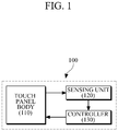
- FIG. 1 is a block diagram of an exemplary touch panel 100
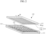
- FIG. 2 is an exploded, perspective view showing a configuration of a touch panel body 110 of the touch panel 100 illustrated in FIG. 1
- FIG. 3 is a cross-sectional view of the touch panel body 110 cut along a line III-III' of FIG. 2 .
- the touch panel 100 includes a touch panel body 110, a sensing unit 120 and a controller 130.
- the touch panel body 110 is a physical structure included in the touch panel 100.
- the sensing unit 120 and controller 130 may be electrical circuits and/or a combination of hardware and software, or only software which sense any input to the touch panel body 110 to control driving of the touch panel body 110. Accordingly, the term "touch panel” used in this specification may indicate only the touch panel body 110 in a narrow sense, but also may indicate the entire touch panel 100 including all of the touch panel body 110, the sensing unit 120 and the controller 130 in a broad sense.
- the sensing unit 120 and controller 130 are shown to be divided for logical classification according to their functions, however they may be integrated into a single unit or implemented as separate devices.
- the logical function classification between the sensing unit 120 and controller 130 is for convenience of description.
- a single integrated component may perform all functions of the sensing unit 120 and controller 130, or some functions of one (for example, the sensing unit 120) of the sensing unit 120 and controller 130 may be performed by the other one (for example, the controller 130).
- a configuration of the touch panel body 110 will be described in detail with reference to FIGS. 2 and 3 .
- the touch panel body 110 includes a pair of substrates (that is, a lower substrate 111 and a upper substrate 112), electro-rheological fluid 113 that is filled and sealed in the gap between the lower substrate 111 and the upper substrate 112, and driving electrode arrays in which driving electrodes are arranged in pairs.
- the lower substrate 111 which is a base substrate of the touch panel body 110, acts as one side of a container for filling the electro-rheological fluid 113 in the touch panel body 110.
- the lower substrate 111 may be a display plane of the electronic device or a substrate attached additionally onto the display plane.
- the lower substrate 111 may be configured so as not to be deformed when a certain attraction force or repulsive force is applied between the lower substrate 111 and the upper substrate 112. That is, the lower substrate 111 may be made of a rigid or hard material.
- the lower substrate 111 may be made of transparent glass.
- the lower substrate 111 may be made of a material that not a hard material.
- the lower substrate 111 may be made of a transparent polymer film.
- the upper surface of the upper substrate 112 is a user touch surface which a user contacts to input a signal.
- the upper substrate 112 may be deformed when predetermined force is applied thereto.
- the upper substrate 112 may be deformed when a user contacts or presses the user touch surface with a finger, a stylus pen, etc.
- the upper substrate 112 may be made of a transparent, deformable polymer film or the like.
- the type of polymer usable for the upper substrate 112 is not limited.
- the upper substrate 112 is spaced a predetermined distance apart from the lower substrate 111 and accordingly a gap having a predetermined thickness is formed between the upper and lower substrates 112 and 111.
- the thickness of the gap may be set appropriately in consideration of a driving voltage, the width of the touch panel body 110, a cross-sectional area of each driving electrode pair 114, etc.
- the electro-rheological fluid 113 is disposed in the gap between the lower and upper substrates 111 and 112.
- the electro-rheological fluid 113 may be sealed with sealant 116 may be applied along facing edge portions of one or both of the upper and lower substrates 112 and 111.
- the electro-rheological fluid 113 is a suspension in which fine particles 113b are dispersed in electro-insulative fluid 113a.
- the viscosity of the electro-rheological fluid 113 can change by a factor of about 100,000 as a maximum when an electric field is applied thereto, and since such variation in viscosity is reversible, the viscosity returns to its original level when the electronic field disappears.
- the electro-rheological fluid 113 may be a transparent liquid such as, for example, silicon oil, kerosene mineral oil, olefin (PCBs), or the like.
- the electro-rheological fluid 113 may be any other material that possesses similar properties of low viscosity change with changing temperature, high flash point, low freezing point, etc. and for which the viscosity changes as a function of the electric field applied thereto.
- the particles 113b included in the electro-rheological fluid 113 may be very fine, transparent particles having a size of maximally about 50 ⁇ m.
- the particles 113b may be polymers, such as aluminosilicate, polyaniline, polypyrrole, or fullerene, or any other kind of insulative materials, such as ceramics or the like.
- Non-transparent ERF may also be used in some applications.
- spacers 115 may be provided in a dispersed manner in the gap between the upper and lower substrates 112 and 111.
- the spacers 115 are elastic elements made of small, transparent particles whose size is less than about several tens of micrometers and are randomly distributed in the electro-rheological fluid 113.
- the spacers 115 shown in FIG. 2 are exaggerated in size, and the arrangement of the spacers 115 shown as if they are dispersed at regular intervals is also exemplary for convenience of description, and in reality the spacers 115 are more likely to be randomly dispersed.
- Materials used to form the spacers 115 are not limited, and for example, the spacers 115 may be made of elastomer.
- the spacers 115 are used to provide the upper substrate 112 with restoring force and to support the upper substrate 112 structurally. That is, the spacers operate as elastic elements between the upper and lower substrate, and allow the substrates to recover to the original film shape in a very short time after a click operation, which will be described later.
- the spacers are advantageously spaced throughout the touch panel, but other types of distribution patterns may be used as long as the spacers may provide the restoring force and structural support. As discussed above, the distribution may also be random. For example, at the edges of the touch panel, the film tension is stronger than that of the center portion. Thus, it may be possible to use fewer spacers in the edge regions. That is, the spacer distribution may also vary depending on the location within the touch panel.
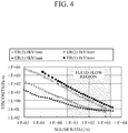
- FIG. 4 is a graph showing a relationship between a driving voltage to be applied to the driving electrode pairs 114 and viscosity of the electro-rheological fluid 113.
- a shear rate generated when the touch panel 100 is driven may be in the range of about 5 (1/s) to about 3000 (1/s). In FIG. 4 , this range is denoted by "fluid flow region.”
- FIG. 4 shows variations in viscosity of two kinds of electro-rheological fluids (one (ER(1)) is a widely commercialized electro-rheological fluid and the other (ER(2)) is a so-called "Pani-Clay 15%", however, these are only exemplary) when a driving voltage of 1 kV/mm is applied to the driving electrode pairs 114 (that is, when a driving voltage of 1 kV is applied to the driving electrode pairs 114, wherein in each electrode pair the driving electrodes are spaced a distance of 1 mm apart from each other), and when the driving voltage is no longer applied to the driving electrode pairs 114 (0 Kv/mm). It can be seen in FIG.
- a viscosity of the electro-rheological fluid 113 when applying a driving voltage is several tens or hundreds higher than that of the electro-rheological fluid 113 when applying no driving voltage for both fluids (ER(1)) and (ER(2)).
- the driving electrode pairs 114 are arranged on the lower and upper substrates 111 and 112 such that driving electrodes disposed on the lower substrate 111 are paired with those disposed on the upper substrate 112.
- a bias voltage that is, a driving voltage
- an electrical field is generated locally in the gap between the upper and lower substrates 112 and 111 where the driving electrode pairs 114 are positioned.
- the viscosity of electro-rheological fluid 113 is increased.
- FIG. 3 shows a single top electrode 114b and a plurality of bottom electrodes 114a when viewed from the side view (also see FIG. 2 ).
- this arrangement is only exemplary. It is also possible to provide an MxN array of electrodes on both the top and bottom, such that each individual pair of electrodes (top and bottom) is separately addressable and controllable(see FIG. 10 ).
- the driving electrode pairs 114 may be arranged in the form of an array over the entire touch panel body 110 or arranged in the form of a matrix. In the case of arranging the driving electrode pairs 114 in the form of an array, a driving voltage may be applied to individual combinations of the driving electrode pairs 114 in order to supply the driving voltage only to selected driving electrode pairs. In addition, varying a combination of the driving electrode pairs 114 to which a driving voltage is to be applied or changing a driving voltage that is to be applied to the driving electrode pairs 114 may provide a user who conducts a continuous input with various tactile sensations, which will be described later.
- FIG. 2 shows an example of driving electrodes that are arranged in the form of a matrix, wherein a plurality of lower electrode patterns 114a are arranged in parallel on the upper surface of the lower substrate 111 and a plurality of upper electrode patterns 114b are arranged in parallel on the lower surface of the upper substrate 112.
- the lower electrode patterns 114a extend in a first direction and the upper electrode patterns 114b extend in a second direction perpendicular to the first direction.
- driving electrode pairs 114 are defined which are arranged in the form of an array throughout the entire area of the touch panel body 110.
- upper and lower electrodes that are each formed as a dot may be arranged in an array over the entire surface of the upper and lower substrates 112 and 111.
- the upper and lower driving electrodes may each be an active device allowing switching.
- the driving voltage may be a power source which drives the touch panel 100 to vary the viscosity of the electro-rheological fluid 113.
- the driving voltage may be supplied from a power supply of an electronic device with the touch panel 100.
- the locations of driving electrode pairs 114 to which the driving voltage is to be applied and/or the level of the driving voltage are controlled by the controller 130 (see FIG. 1 ) of the touch panel 100.
- a driving voltage is applied only to driving electrode pairs disposed in the I area whereas no driving voltage is applied to driving electrode pairs disposed in the II areas.
- a method of applying a driving voltage only to specific driving electrode pairs and adjusting a driving voltage that is to be applied to driving electrode pairs has little direct relation to the technical feature of the current embodiment and accordingly, detailed descriptions thereof will be omitted.
- the touch panel 100 described above may be configured to generate input buttons on the user touch surface of the touch panel 100 and offer, when a user presses one of the input buttons without conducting a continuous input, the user with a clicking sensation similar to that felt when pressing a mechanical button.
- input buttons may be defined in a certain form on the user touch surface so that a user may recognize areas (that is, areas of driving electrode pairs to which a driving voltage is applied, like the I area of FIG.
- the sensing unit 120 determines whether a user's input to the touch panel 100 occurs and calculates, when a user's input is sensed, an input location where the user's input occurs.
- a method in which the sensing unit 120 detects a user's input is not limited.
- the sensing unit 120 may sense a user's input and the input location by detecting a change in capacitance at a certain location on a user touch surface of the upper substrate 112 (see FIG. 2 ), caused by the user's contact to the location.
- Information regarding the input location calculated by the sensing unit 120 is output to the controller 130.
- the controller 130 operates to vary the viscosity of electro-rheological fluid 113 below at least one peripheral region of the input location perceived based on the input location information.
- the viscosity of electro-rheological fluid 113 below other regions than the peripheral region of the input location may also vary.
- the viscosity of electro-rheological fluid 113 may vary depending on the intensity of an electric field applied thereto (see FIG. 4 ).
- the controller 130 may vary the viscosity of electro-rheological fluid 130 by controlling a driving voltage to be applied to various driving electrode pairs 114.
- the controller 130 may select locations (for example, the area I of FIG. 3 ) corresponding to driving electrode pairs to which a driving voltage is to be applied, to control the locations at which the viscosity of the electro-rheological fluid 113 will be varied.
- the driving voltage may be controlled based on absolute criteria or controlled relative to the previously applied driving voltage.
- the touch panel 100 may provide various tactile sensations to a user who conducts a continuous input such as sliding or tracing motion against the user touch surface.
- the controller 130 may determine whether a current input is a continuous input based on input locations calculated by the sensing unit 120. For example, when input coordinates sensed by the sensing unit 120 continue to vary over time, the controller 130 may consider the corresponding input as a continuous input. The time may be a predetermined time.
- the current embodiment is not limited to this example.
- the sensing unit 120 determines whether an input from a user is a continuous input, and transfers, when determining that the input is a continuous input, the result of the determination result to the controller 130 along with information regarding input locations.
- a continuous input is an input whose input location continues to vary over a certain time period, and the traveling path of a continuous input or the type of an instruction that will be executed by such a continuous input is not limited.
- the traveling path of a continuous input may be in a horizontal direction, in a vertical direction, in a diagonal direction, in a zigzag direction, in an out and back manner, etc.
- an input operation such as a "pinch” operation using two fingers at once is conducted or when an input operation is combined with another operation such as a "tapping" operation, the input operation may be considered as a continuous input if the input location varies over time.
- a continuous input is recognized as a predetermined instruction through a predetermined gesture
- a continuous input is recognized as a predetermined instruction in association with a displayed screen. For example, dragging & dropping one (for example, a file) of displayed objects, moving a scroll bar up and down and/or left and right, moving a playing time adjusting bar or a volume adjusting bar up and down and/or left and right, etc. may be examples of continuous inputs.
- the controller 130 controls the viscosity of the electro-rheological fluid 113.
- the controller 130 operates to locally vary the viscosity of electro-rheological fluid below peripheral regions of a current input location, that is, the latest input location among input locations at which the continuous input occurs.
- the "peripheral regions of the latest input location” need not be limited to peripheral regions in a predicted traveling direction (for example, a direction in which the continuous input has headed to reach the latest input location) of the continuous input. This is because the traveling path of a continuous input may arbitrarily be varied by a user.
- the "peripheral regions of the latest input location” may be regions adjacent in all directions to the latest input location, as illustrated in FIG. 5 .
- the "peripheral regions of the latest input location” may be regions adjacent in the front and back directions to the latest input location. That is, the "peripheral regions of the latest input location” may be regions adjacent to the current input position along the scroll bar, the playing time adjusting bar, the volume adjusting bar, etc. For example, in FIG.
- the regions adjacent to the box having the circle therein are varied in the horizontal direction in the figure.
- the controller 130 may control the locations of driving electrode pairs to which a driving voltage is to be applied among the arrays of driving electrode pairs or may control a driving voltage that is to be applied to the corresponding driving electrode pairs, which has been described above.
- a driving voltage with a different level from a driving voltage being applied to the latest or current input location is applied to driving electrode pairs corresponding to the peripheral regions of the latest or current input location, the user who conducts the continuous input may have a different tactile sensation (for example, a different strength of repulsive force) over time.
- a driving voltage with a level that is comparable to the driving voltage being applied to the latest input location may be applied to the peripheral regions of the latest input location.
- the driving voltage may be applied only during a time period for which the input from the user is determined to be a continuous input or only during a time period for which the input location continues to vary.
- the driving voltage with the level comparable to the driving voltage being applied to the latest input location is continually applied to the peripheral regions of the latest input location.
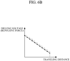
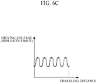
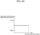
- FIGS. 6A through 6D are graphs showing exemplary driving voltage patterns that are to be applied to the peripheral regions of the latest input location.
- the vertical axis represents a level of a driving voltage that is applied to the peripheral regions of the latest input location with respect to a traveling distance of a continuous input.
- an increase or decrease of a driving voltage increases or decreases the viscosity of electro-rheological fluid.
- the increase or decrease in viscosity of electro-rheological fluid increases or decrease a rigid sensation that a user can feel. Since the input location of a continuous input varies over time, the locations of the peripheral regions also vary over time. That is, as a current input location moves, the peripheral regions of the current input location also move along the traveling path of the continuous input.
- a driving voltage increases in proportion to the traveling distance of a continuous input.
- the driving voltage may increase linearly (as denoted by a straight line) or may increase stepwise (as denoted by a stepped dotted line).
- the level of a driving voltage to be initially applied and the slope of the increasing driving voltage are not limited.
- the slope of the increasing driving voltage does not need to be constant and may vary depending on the traveling distance of the continuous input or the content of a display screen (for example, existence of objects, window borders, etc.).
- An increase in the driving voltage increases the viscosity of electro-rheological fluid below the peripheral regions of the current input location and accordingly a rigid sensation that a user can feel also increases.
- a driving voltage decreases as the traveling distance of a continuous input increases.
- the driving voltage may decrease linearly (a straight line) or stepwise (a dotted line).
- the level of a driving voltage to be initially applied and the slope of the decreasing driving voltage are not limited.
- the slope of the increasing driving voltage does not need to be constant and may vary depending on the traveling distance of the continuous input or the content of a display screen (for example, existence of objects, window borders, etc.). Since the increase or decrease of the driving voltage increases or decreases the viscosity of electro-rheological fluid below the peripheral regions of the current input location, a user may experience great or small repulsive force correspondingly.
- a driving voltage rises and falls alternately along with a traveling distance of a continuous input.
- the driving voltage may rise and fall continuously like a sine wave or discontinuously like a pulse wave.
- the amplitude or period of such a sine wave or pulse wave may be constant regardless of or vary depending on the traveling distance of the continuous input.
- the alternate rising and falling of the driving voltage alternately increases and decreases the viscosity of electro-rheological fluid below the peripheral regions of a current input location, so that a user may experience alternately great and small repulsive force correspondingly.
- a driving voltage is maintained constant regardless of a traveling distance of a continuous input.
- the driving voltage may be set as a minimum voltage (MIN) or a maximum voltage (MAX) at which a touch panel can operate normally, or as an arbitrary voltage between the minimum driving voltage (MIN) and the maximum driving voltage (MAX).
- MIN minimum voltage
- MAX maximum voltage
- the viscosity of electro-rheological fluid is also maintained constant, so that a user may experience constant repulsive force while conducting the continuous input.
- the driving voltage patterns shown in FIGS. 6A through 6D may be individually applied for a continuous input, or two or more of the driving voltage patterns may be combined and applied for a continuous input.
- the magnitude, increasing or decreasing slope, period and/or amplitude of each driving voltage pattern may vary.
- a driving voltage pattern may be pre-set for an electronic device with a touch panel or set arbitrarily by a user who conducts a predetermined continuous input. In the latter case, it will be apparent to those skilled in the art that a driving voltage pattern may be selected depending on the type of a continuous input and/or a kind of an instruction that is to be executed by a continuous input.
- various tactile sensations or repulsive force variations according to the types of continuous inputs may be provided to users.
- the touch panel 100 is implemented as a touch screen
- various tactile sensations may be provided to a user in consideration of kinds of objects displayed on a display of the touch screen, the existence or absence of window borders, or the kinds of instructions that are to be executed through continuous inputs, etc.
- the user may recognize whether continuous input is being conducted correctly only by tactile sensation without having to view a displayed screen.
- an example of offering various tactile sensations in regard to the types of continuous inputs will be described in detail.
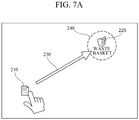
- FIG. 7A illustrates an exemplary continuous input to drag and drop a specific object
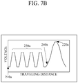
- FIG. 7B shows an exemplary driving voltage pattern that is applied when the continuous input illustrated in FIG. 7A is conducted.
- a user inputs an instruction for dragging and dropping an icon (for example, a certain file) displayed on a screen from its initial location 210 to a target location 220.
- an icon for example, a certain file
- FIG. 7B while the user drags the icon (230), a driving voltage that is applied to the peripheral regions of a current input location (that is, the latest input location) is in a pulse wave form.
- the viscosity of electro-rheological fluid below the peripheral regions alternately increases and decreases along with the movement of the current input location.
- the user who slides a user touch surface of the screen with his or her finger may experience an alternate increase and decrease in rigidity of the screen.
- Applying a driving voltage in the pulse wave form may be repeated until the icon 210 reaches the target location 220.
- the driving voltage is applied in the form of alternately increasing and decreasing pulses until the icon 210 reaches a first location 240 near the target location 220, and after the first location 240, the driving voltage continues to increase gradually.
- the driving voltage continues to increase, the user may feel a continuous increase in rigidity of the screen after the first location 240 and thus recognize with his or her tactile sensation that the current input location is approaching the target location 220.
- a highest driving voltage may be applied to inform the user of completion of all inputs (drag & drop).
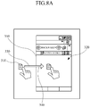
- FIG. 8A illustrates another exemplary continuous input to drag & drop a certain object while crossing a window border
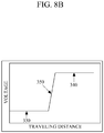
- FIG. 8B shows an exemplary driving voltage pattern that is applied when the continuous input illustrated in FIG. 8A is conducted.
- a user inputs an instruction for dragging and dropping an icon (for example, a certain file) displayed on a screen from its initial location 310 to a target location 320 which is in a window screen, while crossing a window border 350.
- an icon for example, a certain file
- FIG. 8B while the user drags the icon 310 along a line 330 before crossing the window border 350, no driving voltage or a low level of a driving voltage is applied to the peripheral regions of a current input location (the latest input location).
- a relatively high level of driving voltage 340 is applied to the peripheral regions of the current input location.
- the user may feel little repulsive force or very small repulsive force against the screen when beginning to conduct a continuous input, and thereafter feel very great repulsive force against the screen after the item 310 has crossed the window border 350. Accordingly, due to the difference in repulsive force, the user may recognize whether or not the current input location crosses the window border 350 with his or her tactile sensation.
- a different driving voltage pattern for example, a pulse wave, a sine wave, etc.
- an inverse voltage pattern to that shown in FIG. 8B may be applied such that a user experiences the icon 310 "falling into” the target area 320.
- FIG. 9A shows another example of a continuous input
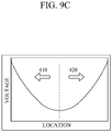
- FIGS. 9B and 9C show exemplary driving voltage patterns that are applied when the continuous input illustrated in FIG. 9A is conducted.
- a driving voltage which is applied to peripheral regions of a current input location (the latest input location) while a user moves a scroll bar up and down is in a pulse wave form, wherein the amplitude of the driving voltage may be pre-set based on the locations of the scroll bar.
- the viscosity of electro-rheological fluid below the peripheral regions of a current input location alternately increases and decreases along with the movement of the current input location.
- a driving voltage that is applied to the peripheral regions of the current input location continues to increase, wherein the amplitude of the driving voltage may be pre-set based on a start position of the scroll bar.
- the higher driving voltage is applied.
- the user may feel a small repulsive force against the screen and experience a low-speed scrolling, and when moving the scroll bar far away from the start position, a large repulsive force may be felt against the screen creating an experience of a fast-speed scrolling. Accordingly, it is possible to adjust a scroll speed only by use of tactile sensation.
- the touch panel 100 provides a user with various tactile sensations upon conducting a continuous input so that the user can intuitively recognize a timing for terminating the continuous input and also is prevented from conducting any wrong inputs. Furthermore, when scrolling in a region of the touch panel 100, a user may have a tactile sensation similar to that felt when rolling a scroll wheel of a mouse to be able to recognize an exact scrolled location and adjust scrolling accurately.
- the touch panel 100 may adjust repulsive force to provide the user with resistance similar to that felt when turning real pages.
- touch panels By utilizing touch panels according to the above-described embodiments, it is possible to offer a sense of input or a tactile sensation to a user who conducts a continuous input.
- a user who conducts a continuous input on the touch panel may be prevented from conducting wrong inputs because the user can recognize a location at which the continuous input has to be terminated, or the existence of any objects or any window border on a traveling path of the continuous input through tactile sensation.
Landscapes
- Engineering & Computer Science (AREA)
- General Engineering & Computer Science (AREA)
- Theoretical Computer Science (AREA)
- Human Computer Interaction (AREA)
- Physics & Mathematics (AREA)
- General Physics & Mathematics (AREA)
- Position Input By Displaying (AREA)
- User Interface Of Digital Computer (AREA)
Claims (14)
- Touch-Panel, umfassend: ein erstes Substrat (111);
ein zweites Substrat (112), das von dem ersten Substrat durch einen Spalt beabstandet ist, wobei das zweite Substrat eine Berührungsfläche umfasst;
ein elektrorheologisches Fluid (113), das in einen Spalt zwischen dem ersten Substrat und dem zweiten Substrat gefüllt wird;
einen Sensor (120), der angeordnet ist, um eine Eingabe auf der Berührungsfläche zu erfassen und eine Eingabestelle zu bestimmen, an der die Eingabe auftritt; und
eine Steuerung (130), die angeordnet ist, um eine Viskosität des elektrorheologischen Fluids an einer Stelle entsprechend einer peripheren Region der Eingabestelle zu variieren,
dadurch gekennzeichnet, dass die Steuerung (130) angeordnet ist, um auf der Grundlage der Eingabestelle zu bestimmen, ob die Eingabe eine sich bewegende Eingabe ist, und, wenn bestimmt wurde, dass die Eingabe eine sich bewegende Eingabe ist, die Viskosität des elektrorheologischen Fluids an einer Stelle entsprechend einer peripheren Region einer letzten Eingabestelle unter Eingabestellen, die von der Abtasteinheit bestimmt wird, zu variieren, wobei die Steuerung angeordnet ist, um die peripheren Regionen der aktuellen Eingabestellen entlang der Bewegungsbahn der sich bewegenden Eingabe gemeinsam mit der aktuellen Eingabestelle zu bewegen. - Touch-Panel nach Anspruch 1,
wobei die Steuerung (130) angeordnet ist, um die Viskosität des elektrorheologischen Fluids an einer Stelle entsprechend der peripheren Region der Eingabestelle zu variieren, gemäß mindestens eines Verfahrens, das ausgewählt wird aus:einem ersten Verfahren des Erhöhens der Viskosität des elektrorheologischen Fluids entlang einer Bewegungsbahn der sich bewegenden Eingabe,einem zweiten Verfahren des Reduzierens der Viskosität des elektrorheologischen Fluids entlang der Bewegungsbahn der sich bewegenden Eingabe,einem dritten Verfahren des konstanten Beibehaltens der Viskosität des elektrorheologischen Fluids, unabhängig von der Bewegungsbahn der sich bewegenden Eingabe, undeinem vierten Verfahren des wechselnden Erhöhens und Reduzierens der Viskosität des elektrorheologischen Fluids entlang der Bewegungsbahn der sich bewegenden Eingabe. - Touch-Panel nach Anspruch 2, wobei die Steuerung (130) angeordnet ist, um die Viskosität des elektrorheologischen Fluids an der Stelle entsprechend der peripheren Region der letzten Eingabestelle in Bezug auf die Viskosität des elektrorheologischen Fluids and der Stelle entsprechend der letzten Eingabestelle zu variieren.
- Touch-Panel nach Anspruch 2 oder 3, wobei die Steuerung (130) angeordnet ist, um eine Benutzereingabe anzunehmen, um das mindestens eine Verfahren auszuwählen, das die Steuerung verwendet, um die Viskosität des elektrorheologischen Fluids zu variieren.
- Touch-Panel nach einem der vorstehenden Ansprüche, ferner umfassend eine Vielzahl von Antriebselektrodenanordnungen, in denen Antriebselektroden auf dem ersten Substrat und dem zweiten Substrat angeordnet sind, sodass die Antriebselektroden Antriebselektrodenpaare (114) bilden, wobei jedes der Antriebselektrodenpaare eine Antriebselektrode auf dem ersten Substrat und eine entsprechende Antriebselektrode auf dem zweiten Substrat beinhaltet,
wobei die Steuerung angeordnet ist, um Stellen, an denen eine Antriebsspannung durch ein entsprechendes Antriebselektrodenpaar (114) anzulegen ist, und eine Amplitude der Antriebsspannung zu steuern, die auf die Antriebselektrodenpaare anzulegen ist. - Touch-Panel nach einem der vorstehenden Ansprüche, ferner umfassend:eine Vielzahl von Antriebselektrodenanordnungen (114), in denen Antriebselektroden auf dem ersten Substrat und dem zweiten Substrat angeordnet sind, sodass die Antriebselektroden Antriebselektrodenpaare (114) bilden, wobei jedes der Antriebselektrodenpaare (114) eine Antriebselektrode auf dem ersten Substrat und eine entsprechende Antriebselektrode auf dem zweiten Substrat beinhaltet und jedes der Antriebselektrodenpaar dazu konfiguriert ist,ein elektrisches Feld lokal zwischen dem ersten Substrat und dem zweiten Substrat bei Anwendung einer Antriebsspannung zu induzieren;wobei eine Viskosität des elektrorheologischen Fluids durch ein elektrisches Feld verändert wird, das von den Antriebselektrodenpaaren induziert wird; unddie Steuerung (130) angeordnet ist, wenn eine sich bewegende Eingabe von einem Benutzer auf der Berührungsfläche erfasst wird, ein Antriebsspannungsmuster auf die Antriebselektrodenpaare an einer Stelle entsprechend mindestens einer peripheren Region einer letzten Eingabestelle unter Stellen, an der die sich bewegende Eingabe erfasst wird, anzulegen.
- Touch-Panel nach Anspruch 6, wobei das Antriebsspannungsmuster mindestens ein Muster ist, das ausgewählt wird aus:einem ersten Muster, wo die Antriebsspannung entlang einer Bewegungsbahn der sich bewegenden Eingabe zunimmt,einem zweiten Muster, wo die Antriebsspannung entlang einer Bewegungsbahn der sich bewegenden Eingabe abnimmt,einem dritten Muster, wo die Antriebsspannung konstant gehalten wird, unabhängig von der Bewegungsbahn der sich bewegenden Eingabe, undeinem vierten Muster, wobei die Antriebsspannung entlang der Bewegungsbahn der sich bewegenden Eingabe abwechselnd zunimmt und abnimmt,und wobei das Antriebsspannungsmuster optional vom Benutzer auswählbar ist.
- Touch-Panel nach Anspruch 7, wobei die Steuerung (130) angeordnet ist, die Antriebsspannung durch Variieren einer Amplitude der Antriebsspannung, die auf die Antriebselektrodenpaare (114) anzulegen ist, an der Stelle entsprechend der peripheren Region der letzten Eingabestelle zu erhöhen oder zu reduzieren.
- Touch-Panel nach Anspruch 7 oder 8, wobei das vierte Muster dazu konfiguriert ist, die Antriebsspannung gemäß einer Sinuswellenform oder einer Impulswellenform entlang der Bewegungsbahn der sich bewegenden Eingabe zu variieren, und wobei optional mindestens eines einer Amplitude und Frequenz der Sinuswelle oder der Impulswelle variabel ist.
- Touch-Panel nach einem der Ansprüche 6 bis 9, wobei das Touch-Panel in eine Anzeige einer elektronischen Vorrichtung als ein Touchscreen integriert ist, und
die Steuerung (130) angeordnet ist, um eine Amplitude der Antriebsspannung, die auf die Antriebselektrodenpaare (140) anzulegen ist, an der Stelle entsprechend der peripheren Region der letzten Eingabestelle auf der Grundlage eines Abstands von der letzten Eingabestelle zu einem Objekt, das auf dem Touchscreen angezeigt wird, zu steuern, wobei das Objekt auf dem Touchscreen von der letzten Eingabestelle beabstandet ist, und optional die Steuerung angeordnet ist, um die Amplitude der zu erhöhenden Antriebsspannung zu steuern, wenn der Abstand zwischen dem Objekt und der letzten Eingabestelle abnimmt, wobei eine maximale Amplitude erreicht wird, kurz bevor die letzte Eingabestelle das Objekt erreicht. - Touch-Panel nach einem der Ansprüche 6 bis 9, wobei das Touch-Panel in eine Anzeige einer elektronischen Vorrichtung als ein Touchscreen integriert ist, und
die Steuerung angeordnet ist, um eine Amplitude der Antriebsspannung, die auf die Antriebselektrodenpaare angelegt wird, an einer Stelle entsprechend der peripheren Region auf der Grundlage eines Abstands von der letzten Eingabestelle zu einem Fensterrand, der auf dem Touchscreen angezeigt wird, zu steuern, wobei der Fensterrad auf dem Touchscreen von der letzten Eingabestelle beabstandet ist, und optional die Steuerung angeordnet ist, um die Amplitude der zu erhöhenden oder zu reduzierenden Antriebsspannung zu steuern, wenn der Abstand zwischen dem Fensterrand und der letzten Eingabestelle abnimmt, um ein Maximum bzw. ein Minimum zu erreichen, kurz bevor die letzte Eingabestelle den Fensterrand erreicht. - Touch-Panel nach Anspruch 6, wobei das Touch-Panel in eine Anzeige einer elektronischen Vorrichtung als ein Touchscreen integriert ist, wobei eine Bildlaufleiste auf dem Touchscreen angezeigt ist und die sich bewegende Eingabe die Bildlaufleiste zu bewegen hat.
- Touch-Panel nach Anspruch 12, wobei die Steuerung (130) angeordnet ist, um die Antriebsspannung, die auf die Antriebselektrodenpaare, die eine Impulswellenform aufzuweisen haben, angelegt wird, zu steuern, und die Steuerung angeordnet ist, um eine Amplitude der Antriebsspannung auf der Grundlage eines Bereichs, in dem die Bildlaufleiste auf dem Touchscreen bewegbar ist, zu steuern.
- Elektronische Vorrichtung mit dem Touch-Panel nach einem der Ansprüche 6 bis 13 als eine Benutzereingabeschnittstelle.
Applications Claiming Priority (1)
| Application Number | Priority Date | Filing Date | Title |
|---|---|---|---|
| KR1020100001443A KR101616875B1 (ko) | 2010-01-07 | 2010-01-07 | 터치 패널 및 이를 구비한 전자기기 |
Publications (3)
| Publication Number | Publication Date |
|---|---|
| EP2343627A2 EP2343627A2 (de) | 2011-07-13 |
| EP2343627A3 EP2343627A3 (de) | 2013-04-17 |
| EP2343627B1 true EP2343627B1 (de) | 2017-09-27 |
Family
ID=43798584
Family Applications (1)
| Application Number | Title | Priority Date | Filing Date |
|---|---|---|---|
| EP11150285.2A Not-in-force EP2343627B1 (de) | 2010-01-07 | 2011-01-06 | Berührungsbildschirm und diesen umfassende elektronische Vorrichtung |
Country Status (5)
| Country | Link |
|---|---|
| US (1) | US8791908B2 (de) |
| EP (1) | EP2343627B1 (de) |
| JP (1) | JP5770457B2 (de) |
| KR (1) | KR101616875B1 (de) |
| CN (1) | CN102122215B (de) |
Families Citing this family (97)
| Publication number | Priority date | Publication date | Assignee | Title |
|---|---|---|---|---|
| US8947383B2 (en) * | 2008-01-04 | 2015-02-03 | Tactus Technology, Inc. | User interface system and method |
| US9557915B2 (en) | 2008-01-04 | 2017-01-31 | Tactus Technology, Inc. | Dynamic tactile interface |
| US9552065B2 (en) | 2008-01-04 | 2017-01-24 | Tactus Technology, Inc. | Dynamic tactile interface |
| US9274612B2 (en) | 2008-01-04 | 2016-03-01 | Tactus Technology, Inc. | User interface system |
| US9760172B2 (en) | 2008-01-04 | 2017-09-12 | Tactus Technology, Inc. | Dynamic tactile interface |
| US8970403B2 (en) | 2008-01-04 | 2015-03-03 | Tactus Technology, Inc. | Method for actuating a tactile interface layer |
| US9063627B2 (en) | 2008-01-04 | 2015-06-23 | Tactus Technology, Inc. | User interface and methods |
| US9430074B2 (en) | 2008-01-04 | 2016-08-30 | Tactus Technology, Inc. | Dynamic tactile interface |
| US8547339B2 (en) | 2008-01-04 | 2013-10-01 | Tactus Technology, Inc. | System and methods for raised touch screens |
| US9298261B2 (en) | 2008-01-04 | 2016-03-29 | Tactus Technology, Inc. | Method for actuating a tactile interface layer |
| US9588683B2 (en) | 2008-01-04 | 2017-03-07 | Tactus Technology, Inc. | Dynamic tactile interface |
| US9612659B2 (en) | 2008-01-04 | 2017-04-04 | Tactus Technology, Inc. | User interface system |
| US9052790B2 (en) | 2008-01-04 | 2015-06-09 | Tactus Technology, Inc. | User interface and methods |
| US9128525B2 (en) | 2008-01-04 | 2015-09-08 | Tactus Technology, Inc. | Dynamic tactile interface |
| US8456438B2 (en) * | 2008-01-04 | 2013-06-04 | Tactus Technology, Inc. | User interface system |
| US9013417B2 (en) | 2008-01-04 | 2015-04-21 | Tactus Technology, Inc. | User interface system |
| US9423875B2 (en) | 2008-01-04 | 2016-08-23 | Tactus Technology, Inc. | Dynamic tactile interface with exhibiting optical dispersion characteristics |
| US9367132B2 (en) | 2008-01-04 | 2016-06-14 | Tactus Technology, Inc. | User interface system |
| US8243038B2 (en) | 2009-07-03 | 2012-08-14 | Tactus Technologies | Method for adjusting the user interface of a device |
| US8154527B2 (en) | 2008-01-04 | 2012-04-10 | Tactus Technology | User interface system |
| US9720501B2 (en) | 2008-01-04 | 2017-08-01 | Tactus Technology, Inc. | Dynamic tactile interface |
| US9152258B2 (en) * | 2008-06-19 | 2015-10-06 | Neonode Inc. | User interface for a touch screen |
| US9588684B2 (en) | 2009-01-05 | 2017-03-07 | Tactus Technology, Inc. | Tactile interface for a computing device |
| KR101658991B1 (ko) * | 2009-06-19 | 2016-09-22 | 삼성전자주식회사 | 터치 패널 및 이를 구비한 전자 기기 |
| KR101667801B1 (ko) * | 2009-06-19 | 2016-10-20 | 삼성전자주식회사 | 터치 패널 및 이를 구비한 전자 기기 |
| CN105260110A (zh) | 2009-07-03 | 2016-01-20 | 泰克图斯科技公司 | 用户界面增强系统 |
| WO2011087817A1 (en) | 2009-12-21 | 2011-07-21 | Tactus Technology | User interface system |
| US9239623B2 (en) | 2010-01-05 | 2016-01-19 | Tactus Technology, Inc. | Dynamic tactile interface |
| KR101616875B1 (ko) | 2010-01-07 | 2016-05-02 | 삼성전자주식회사 | 터치 패널 및 이를 구비한 전자기기 |
| KR101631892B1 (ko) * | 2010-01-28 | 2016-06-21 | 삼성전자주식회사 | 터치 패널 및 이를 구비한 전자기기 |
| KR101710523B1 (ko) * | 2010-03-22 | 2017-02-27 | 삼성전자주식회사 | 터치 패널 및 이를 구비한 전자기기 |
| KR101661728B1 (ko) | 2010-05-11 | 2016-10-04 | 삼성전자주식회사 | 사용자 입력 장치 및 이를 구비한 전자 기기 |
| KR101809191B1 (ko) | 2010-10-11 | 2018-01-18 | 삼성전자주식회사 | 터치 패널 |
| WO2012054781A1 (en) | 2010-10-20 | 2012-04-26 | Tactus Technology | User interface system and method |
| CN103109255A (zh) | 2010-10-20 | 2013-05-15 | 泰克图斯科技公司 | 用户接口系统 |
| KR101735715B1 (ko) | 2010-11-23 | 2017-05-15 | 삼성전자주식회사 | 입력 감지 소자 및 이를 구비한 터치 패널 |
| WO2012102054A1 (ja) * | 2011-01-27 | 2012-08-02 | 京セラ株式会社 | 触感呈示装置 |
| KR101784436B1 (ko) | 2011-04-18 | 2017-10-11 | 삼성전자주식회사 | 터치 패널 및 이를 위한 구동 장치 |
| US9417754B2 (en) | 2011-08-05 | 2016-08-16 | P4tents1, LLC | User interface system, method, and computer program product |
| JP2013200863A (ja) | 2012-02-23 | 2013-10-03 | Panasonic Corp | 電子機器 |
| JP2017084404A (ja) * | 2012-02-23 | 2017-05-18 | パナソニックIpマネジメント株式会社 | 電子機器 |
| US20150169059A1 (en) * | 2012-04-18 | 2015-06-18 | Nokia Corporation | Display apparatus with haptic feedback |
| CN104487930A (zh) | 2012-05-09 | 2015-04-01 | 苹果公司 | 用于移动和放置用户界面对象的设备、方法和图形用户界面 |
| WO2013169849A2 (en) | 2012-05-09 | 2013-11-14 | Industries Llc Yknots | Device, method, and graphical user interface for displaying user interface objects corresponding to an application |
| EP2847659B1 (de) | 2012-05-09 | 2019-09-04 | Apple Inc. | Vorrichtung, verfahren und grafische benutzerschnittstelle zum übergang zwischen anzeigezuständen als reaktion auf eine geste |
| WO2013169875A2 (en) | 2012-05-09 | 2013-11-14 | Yknots Industries Llc | Device, method, and graphical user interface for displaying content associated with a corresponding affordance |
| WO2013169843A1 (en) | 2012-05-09 | 2013-11-14 | Yknots Industries Llc | Device, method, and graphical user interface for manipulating framed graphical objects |
| JP6031186B2 (ja) | 2012-05-09 | 2016-11-24 | アップル インコーポレイテッド | ユーザインタフェースオブジェクトを選択するためのデバイス、方法及びグラフィカルユーザインタフェース |
| WO2013169851A2 (en) | 2012-05-09 | 2013-11-14 | Yknots Industries Llc | Device, method, and graphical user interface for facilitating user interaction with controls in a user interface |
| WO2013169842A2 (en) | 2012-05-09 | 2013-11-14 | Yknots Industries Llc | Device, method, and graphical user interface for selecting object within a group of objects |
| CN104508618B (zh) | 2012-05-09 | 2018-01-05 | 苹果公司 | 用于针对在用户界面中执行的操作提供触觉反馈的设备、方法和图形用户界面 |
| WO2013169846A1 (en) | 2012-05-09 | 2013-11-14 | Yknots Industries Llc | Device, method, and graphical user interface for displaying additional information in response to a user contact |
| WO2013169865A2 (en) | 2012-05-09 | 2013-11-14 | Yknots Industries Llc | Device, method, and graphical user interface for moving a user interface object based on an intensity of a press input |
| EP2847662B1 (de) | 2012-05-09 | 2020-02-19 | Apple Inc. | Vorrichtung, verfahren und grafische benutzeroberfläche zur bereitstellung von feedback für sich ändernde aktivierungszustände eines benutzeroberflächenobjekts |
| WO2013169845A1 (en) | 2012-05-09 | 2013-11-14 | Yknots Industries Llc | Device, method, and graphical user interface for scrolling nested regions |
| US9405417B2 (en) | 2012-09-24 | 2016-08-02 | Tactus Technology, Inc. | Dynamic tactile interface and methods |
| CN104662497A (zh) | 2012-09-24 | 2015-05-27 | 泰克图斯科技公司 | 动态触觉界面和方法 |
| US9196134B2 (en) * | 2012-10-31 | 2015-11-24 | Immersion Corporation | Method and apparatus for simulating surface features on a user interface with haptic effects |
| HK1215094A1 (zh) | 2012-12-29 | 2016-08-12 | Apple Inc. | 用於根據具有模擬三維特徵的控制圖標的外觀變化來移動光標的設備、方法和圖形用戶界面 |
| AU2013368443B2 (en) | 2012-12-29 | 2016-03-24 | Apple Inc. | Device, method, and graphical user interface for transitioning between touch input to display output relationships |
| CN107831991B (zh) | 2012-12-29 | 2020-11-27 | 苹果公司 | 用于确定是滚动还是选择内容的设备、方法和图形用户界面 |
| WO2014105279A1 (en) | 2012-12-29 | 2014-07-03 | Yknots Industries Llc | Device, method, and graphical user interface for switching between user interfaces |
| WO2014105274A1 (en) | 2012-12-29 | 2014-07-03 | Yknots Industries Llc | Device, method, and graphical user interface for navigating user interface hierarchies |
| AU2013368441B2 (en) | 2012-12-29 | 2016-04-14 | Apple Inc. | Device, method, and graphical user interface for forgoing generation of tactile output for a multi-contact gesture |
| KR101844303B1 (ko) | 2013-02-25 | 2018-04-02 | 삼성전자주식회사 | 동적 자기장 제어를 이용하여 입출력 인터페이스를 제공하는 입체 영상 장치 및 그 장치를 이용한 방법 |
| US9557813B2 (en) | 2013-06-28 | 2017-01-31 | Tactus Technology, Inc. | Method for reducing perceived optical distortion |
| US20150034469A1 (en) * | 2013-08-05 | 2015-02-05 | Samsung Display Co., Ltd. | Formable input keypad and display device using the same |
| JP6300604B2 (ja) * | 2014-04-01 | 2018-03-28 | キヤノン株式会社 | 触感制御装置、触感制御方法及びプログラム |
| KR20150120730A (ko) * | 2014-04-18 | 2015-10-28 | 삼성전자주식회사 | 물리적 버튼과 이미지 센서를 내장한 디스플레이 모듈과 이의 제조 방법 |
| WO2016075775A1 (ja) * | 2014-11-12 | 2016-05-19 | 富士通株式会社 | 電子機器 |
| US9990107B2 (en) | 2015-03-08 | 2018-06-05 | Apple Inc. | Devices, methods, and graphical user interfaces for displaying and using menus |
| US9632664B2 (en) | 2015-03-08 | 2017-04-25 | Apple Inc. | Devices, methods, and graphical user interfaces for manipulating user interface objects with visual and/or haptic feedback |
| US10095396B2 (en) | 2015-03-08 | 2018-10-09 | Apple Inc. | Devices, methods, and graphical user interfaces for interacting with a control object while dragging another object |
| US10048757B2 (en) | 2015-03-08 | 2018-08-14 | Apple Inc. | Devices and methods for controlling media presentation |
| US9645732B2 (en) | 2015-03-08 | 2017-05-09 | Apple Inc. | Devices, methods, and graphical user interfaces for displaying and using menus |
| US9785305B2 (en) | 2015-03-19 | 2017-10-10 | Apple Inc. | Touch input cursor manipulation |
| US9639184B2 (en) | 2015-03-19 | 2017-05-02 | Apple Inc. | Touch input cursor manipulation |
| US10152208B2 (en) | 2015-04-01 | 2018-12-11 | Apple Inc. | Devices and methods for processing touch inputs based on their intensities |
| US20170045981A1 (en) | 2015-08-10 | 2017-02-16 | Apple Inc. | Devices and Methods for Processing Touch Inputs Based on Their Intensities |
| US10200598B2 (en) | 2015-06-07 | 2019-02-05 | Apple Inc. | Devices and methods for capturing and interacting with enhanced digital images |
| US10346030B2 (en) | 2015-06-07 | 2019-07-09 | Apple Inc. | Devices and methods for navigating between user interfaces |
| US9891811B2 (en) | 2015-06-07 | 2018-02-13 | Apple Inc. | Devices and methods for navigating between user interfaces |
| US9674426B2 (en) | 2015-06-07 | 2017-06-06 | Apple Inc. | Devices and methods for capturing and interacting with enhanced digital images |
| US9860451B2 (en) | 2015-06-07 | 2018-01-02 | Apple Inc. | Devices and methods for capturing and interacting with enhanced digital images |
| US9830048B2 (en) | 2015-06-07 | 2017-11-28 | Apple Inc. | Devices and methods for processing touch inputs with instructions in a web page |
| US10235035B2 (en) | 2015-08-10 | 2019-03-19 | Apple Inc. | Devices, methods, and graphical user interfaces for content navigation and manipulation |
| US10248308B2 (en) | 2015-08-10 | 2019-04-02 | Apple Inc. | Devices, methods, and graphical user interfaces for manipulating user interfaces with physical gestures |
| US9880735B2 (en) | 2015-08-10 | 2018-01-30 | Apple Inc. | Devices, methods, and graphical user interfaces for manipulating user interface objects with visual and/or haptic feedback |
| US10416800B2 (en) | 2015-08-10 | 2019-09-17 | Apple Inc. | Devices, methods, and graphical user interfaces for adjusting user interface objects |
| FR3040928B1 (fr) * | 2015-09-14 | 2017-10-13 | Valeo Comfort & Driving Assistance | Selecteur de commande d'un vehicule automobile et procede de selection d'une commande de vehicule automobile |
| FR3040927B1 (fr) * | 2015-09-14 | 2018-08-17 | Valeo Comfort And Driving Assistance | Selecteur d'une boite de vitesse automatique de vehicule automobile et procede de selection du mode de conduite autonome |
| US9619032B1 (en) | 2015-10-16 | 2017-04-11 | International Business Machines Corporation | Accessibility path guiding through microfluidics on a touch screen |
| JP6685695B2 (ja) * | 2015-10-30 | 2020-04-22 | キヤノン株式会社 | 端末及び撮像装置 |
| US10489043B2 (en) * | 2015-12-15 | 2019-11-26 | International Business Machines Corporation | Cognitive graphical control element |
| JP2019105712A (ja) * | 2017-12-12 | 2019-06-27 | シャープ株式会社 | 表示装置 |
| EP3629128A1 (de) * | 2018-09-25 | 2020-04-01 | Vestel Elektronik Sanayi ve Ticaret A.S. | Benutzervorrichtung und verfahren zur erzeugung einer haptischen rückmeldung in einer benutzervorrichtung |
| DE102019206229A1 (de) * | 2019-04-30 | 2020-11-05 | Zf Friedrichshafen Ag | Bedienelement |
Family Cites Families (106)
| Publication number | Priority date | Publication date | Assignee | Title |
|---|---|---|---|---|
| US4963417A (en) * | 1987-07-03 | 1990-10-16 | Toray Industries, Inc. | Pressure-sensitive tablet |
| US4923057A (en) * | 1988-09-20 | 1990-05-08 | Lord Corporation | Electrorheological fluid composite structures |
| US5055840A (en) * | 1990-01-16 | 1991-10-08 | Carroll Touch Incorporated | Infrared touch input device and light emitted activation circuit |
| DE4012267A1 (de) * | 1990-03-13 | 1991-11-28 | Joerg Fricke | Geraet zur tastbaren darstellung von information |
| JP3170051B2 (ja) | 1992-07-21 | 2001-05-28 | ローム株式会社 | 液晶表示装置 |
| US5959613A (en) * | 1995-12-01 | 1999-09-28 | Immersion Corporation | Method and apparatus for shaping force signals for a force feedback device |
| US5856822A (en) * | 1995-10-27 | 1999-01-05 | 02 Micro, Inc. | Touch-pad digital computer pointing-device |
| US6078308A (en) * | 1995-12-13 | 2000-06-20 | Immersion Corporation | Graphical click surfaces for force feedback applications to provide user selection using cursor interaction with a trigger position within a boundary of a graphical object |
| US6475639B2 (en) * | 1996-01-18 | 2002-11-05 | Mohsen Shahinpoor | Ionic polymer sensors and actuators |
| JPH09319509A (ja) | 1996-05-28 | 1997-12-12 | Toyo Polymer Kk | 入力装置 |
| FR2749955B1 (fr) * | 1996-06-14 | 1998-09-11 | Thomson Csf | Systeme de lecture d'empreintes digitales |
| US6809462B2 (en) * | 2000-04-05 | 2004-10-26 | Sri International | Electroactive polymer sensors |
| US6118435A (en) * | 1997-04-10 | 2000-09-12 | Idec Izumi Corporation | Display unit with touch panel |
| EP1046946B1 (de) * | 1998-01-09 | 2008-05-28 | Nissha Printing Co., Ltd. | Flüssigkristallanzeige mit berührungseingabe und herstellungsverfahren |
| JPH11203025A (ja) | 1998-01-20 | 1999-07-30 | Fuji Xerox Co Ltd | 凹凸形成パネルおよび前記凹凸形成パネルを使用した情報入力装置 |
| US7663607B2 (en) | 2004-05-06 | 2010-02-16 | Apple Inc. | Multipoint touchscreen |
| JPH11273501A (ja) | 1998-03-23 | 1999-10-08 | Tietech Co Ltd | ディスプレイスイッチ用凸状キーの出現制御方式 |
| US5977867A (en) * | 1998-05-29 | 1999-11-02 | Nortel Networks Corporation | Touch pad panel with tactile feedback |
| US6429846B2 (en) * | 1998-06-23 | 2002-08-06 | Immersion Corporation | Haptic feedback for touchpads and other touch controls |
| JP2000066782A (ja) | 1998-08-21 | 2000-03-03 | Fuji Electric Co Ltd | タッチ式座標入力装置用表示補助装置 |
| US6822635B2 (en) * | 2000-01-19 | 2004-11-23 | Immersion Corporation | Haptic interface for laptop computers and other portable devices |
| US7715088B2 (en) * | 2000-03-03 | 2010-05-11 | Sipix Imaging, Inc. | Electrophoretic display |
| JP2001282433A (ja) | 2000-03-31 | 2001-10-12 | Sanyo Electric Co Ltd | 表示入力装置 |
| EP2385518A3 (de) * | 2000-05-24 | 2012-02-15 | Immersion Medical, Inc. | Haptische Vorrichtungen mit elektroaktiven Polymeren |
| JP2002055600A (ja) * | 2000-08-09 | 2002-02-20 | Laurel Seiki Kk | 視覚障害者用情報入出力装置 |
| JP2002157087A (ja) | 2000-11-20 | 2002-05-31 | Sony Corp | 入力装置 |
| JP2002287902A (ja) * | 2001-01-17 | 2002-10-04 | Seiko Epson Corp | タッチパネル及び電子機器 |
| JP2002236550A (ja) * | 2001-02-07 | 2002-08-23 | Fujitsu Ten Ltd | 画面位置入力方法および装置 |
| WO2002089038A2 (en) * | 2001-04-27 | 2002-11-07 | Atrua Technologies, Inc. | Capacitive sensor system with improved capacitance measuring sensitivity |
| JP2002342035A (ja) | 2001-05-22 | 2002-11-29 | Fuji Xerox Co Ltd | タッチパネル入力装置および画像記録装置 |
| US20050030292A1 (en) | 2001-12-12 | 2005-02-10 | Diederiks Elmo Marcus Attila | Display system with tactile guidance |
| US7477242B2 (en) * | 2002-05-20 | 2009-01-13 | 3M Innovative Properties Company | Capacitive touch screen with conductive polymer |
| JP2004071765A (ja) | 2002-08-05 | 2004-03-04 | Sony Corp | 電気粘性流体装置及び電子機器 |
| JP3937982B2 (ja) * | 2002-08-29 | 2007-06-27 | ソニー株式会社 | 入出力装置および入出力装置を有する電子機器 |
| JP2004145456A (ja) * | 2002-10-22 | 2004-05-20 | Canon Inc | 情報出力装置 |
| US20040090426A1 (en) * | 2002-11-07 | 2004-05-13 | Eastman Kodak Company | Transparent flexible sheet for resistive touch screen |
| ATE329361T1 (de) | 2002-12-09 | 2006-06-15 | Koninkl Philips Electronics Nv | Transparentes, berührungsempfindliches umschaltsystem |
| DE10324579A1 (de) | 2003-05-30 | 2004-12-16 | Daimlerchrysler Ag | Bedienvorrichtung |
| JP2004362428A (ja) * | 2003-06-06 | 2004-12-24 | Denso Corp | タッチ操作入力装置、タッチ操作入力装置における振動発生方法 |
| GB0317715D0 (en) | 2003-07-29 | 2003-09-03 | Koninkl Philips Electronics Nv | Display and input device |
| DE10340188A1 (de) * | 2003-09-01 | 2005-04-07 | Siemens Ag | Bildschirm mit einer berührungsempfindlichen Bedienoberfläche zur Befehlseingabe |
| JP4084727B2 (ja) | 2003-09-30 | 2008-04-30 | 日本航空電子工業株式会社 | 光導波路型タッチパネル |
| US20050076824A1 (en) * | 2003-10-08 | 2005-04-14 | Cross Elisa M. | Resistive touch screen incorporating conductive polymer |
| JP4137765B2 (ja) | 2003-10-31 | 2008-08-20 | 日本航空電子工業株式会社 | タッチ式入力装置及びその制御方法 |
| US8164573B2 (en) * | 2003-11-26 | 2012-04-24 | Immersion Corporation | Systems and methods for adaptive interpretation of input from a touch-sensitive input device |
| US20050130604A1 (en) * | 2003-11-26 | 2005-06-16 | Nokia Corporation | Electronic device having a physical configuration that is dependent upon its operational status |
| US7339579B2 (en) * | 2003-12-15 | 2008-03-04 | 3M Innovative Properties Company | Wiring harness and touch sensor incorporating same |
| DE102005003548A1 (de) * | 2004-02-02 | 2006-02-09 | Volkswagen Ag | Bedienelement für ein Kraftfahrzeug |
| KR20060131886A (ko) | 2004-03-17 | 2006-12-20 | 코닌클리케 필립스 일렉트로닉스 엔.브이. | 디스플레이 패널 |
| JP2005275632A (ja) | 2004-03-23 | 2005-10-06 | Fujitsu Component Ltd | 入力パネル及び入力装置 |
| DE602004009408T2 (de) * | 2004-04-22 | 2008-07-17 | Sony Ericsson Mobile Communications Ab | Steuerschnittstelle |
| JP2006011646A (ja) * | 2004-06-23 | 2006-01-12 | Pioneer Electronic Corp | 触覚表示装置及び触覚表示機能付タッチパネル装置 |
| US7342573B2 (en) * | 2004-07-07 | 2008-03-11 | Nokia Corporation | Electrostrictive polymer as a combined haptic-seal actuator |
| US7598949B2 (en) * | 2004-10-22 | 2009-10-06 | New York University | Multi-touch sensing light emitting diode display and method for using the same |
| US7067756B2 (en) * | 2004-11-12 | 2006-06-27 | Eastman Kodak Company | Flexible sheet for resistive touch screen |
| KR100682901B1 (ko) | 2004-11-17 | 2007-02-15 | 삼성전자주식회사 | 화상표시장치에서 전기활성폴리머를 사용하여 영상정보의핑거팁 햅틱을 제공하는 장치 및 방법 |
| JP2006146611A (ja) * | 2004-11-19 | 2006-06-08 | Fujitsu Component Ltd | ハプティックパネル装置 |
| KR100791378B1 (ko) | 2005-12-29 | 2008-01-07 | 삼성전자주식회사 | 다양한 입력 모드를 지원하는 사용자 명령 입력 장치 및이를 이용한 기기 |
| KR100877067B1 (ko) | 2006-01-03 | 2009-01-07 | 삼성전자주식회사 | 햅틱 버튼 및 이를 이용한 햅틱 기기 |
| KR100778761B1 (ko) * | 2006-03-13 | 2007-11-27 | 한국과학기술원 | 유변유체를 이용한 영상의 형상정보 촉감전달장치 및 그방법 |
| US7538760B2 (en) * | 2006-03-30 | 2009-05-26 | Apple Inc. | Force imaging input device and system |
| US7688080B2 (en) * | 2006-07-17 | 2010-03-30 | Synaptics Incorporated | Variably dimensioned capacitance sensor elements |
| JP2008033739A (ja) | 2006-07-31 | 2008-02-14 | Sony Corp | 力覚フィードバックおよび圧力測定に基づくタッチスクリーンインターラクション方法および装置 |
| CN101506758A (zh) | 2006-09-27 | 2009-08-12 | 诺基亚公司 | 触觉型触摸屏 |
| US7990481B2 (en) * | 2006-10-30 | 2011-08-02 | Samsung Electronics Co., Ltd. | Display device having particular touch sensor protrusion facing sensing electrode |
| US7755615B2 (en) * | 2006-12-18 | 2010-07-13 | Motorola, Inc. | Optical shuttered touchscreen and method therefor |
| US7643011B2 (en) | 2007-01-03 | 2010-01-05 | Apple Inc. | Noise detection in multi-touch sensors |
| US9710095B2 (en) * | 2007-01-05 | 2017-07-18 | Apple Inc. | Touch screen stack-ups |
| US8054299B2 (en) | 2007-01-08 | 2011-11-08 | Apple Inc. | Digital controller for a true multi-point touch surface useable in a computer system |
| US7608976B1 (en) * | 2007-02-07 | 2009-10-27 | Auburn University | Electroactive co-polymer systems and devices using the same |
| US7719167B2 (en) * | 2007-05-14 | 2010-05-18 | Samsung Electronics Co., Ltd. | Electroactive polymer actuator and manufacturing method thereof |
| US20090002328A1 (en) | 2007-06-26 | 2009-01-01 | Immersion Corporation, A Delaware Corporation | Method and apparatus for multi-touch tactile touch panel actuator mechanisms |
| US20090002199A1 (en) * | 2007-06-28 | 2009-01-01 | Nokia Corporation | Piezoelectric sensing as user input means |
| EP2026178A1 (de) | 2007-08-10 | 2009-02-18 | IEE INTERNATIONAL ELECTRONICS & ENGINEERING S.A. | Touchpad mit bandförmigem Eingabebereich |
| US20090046068A1 (en) * | 2007-08-13 | 2009-02-19 | Research In Motion Limited | Tactile touchscreen for electronic device |
| US20090046065A1 (en) * | 2007-08-17 | 2009-02-19 | Eric Liu | Sensor-keypad combination for mobile computing devices and applications thereof |
| US8509854B2 (en) | 2007-09-18 | 2013-08-13 | Lg Electronics Inc. | Mobile terminal and method of controlling operation of the same |
| US8098235B2 (en) * | 2007-09-28 | 2012-01-17 | Immersion Corporation | Multi-touch device having dynamic haptic effects |
| US7890257B2 (en) * | 2008-01-14 | 2011-02-15 | Research In Motion Limited | Using a shape-changing display as an adaptive lens for selectively magnifying information displayed onscreen |
| DE602008005699D1 (de) * | 2008-01-14 | 2011-05-05 | Research In Motion Ltd | Verwendung einer formverändernden Anzeige und Anpassungslinse zur selektiven Vergrößerung von Informationen, die auf dem Schirm angezeigt werden |
| WO2009150697A1 (ja) * | 2008-06-11 | 2009-12-17 | パナソニック株式会社 | 導電性高分子アクチュエータおよびその製造方法 |
| KR101474963B1 (ko) * | 2008-07-01 | 2014-12-19 | 엘지전자 주식회사 | 휴대 단말기 및 그 제어방법 |
| KR100901381B1 (ko) | 2008-07-02 | 2009-06-05 | 인하대학교 산학협력단 | 층 구조의 전기활성 폴리머를 이용한 햅틱 버튼 시스템 |
| JP5243118B2 (ja) | 2008-07-03 | 2013-07-24 | アルプス電気株式会社 | 高分子アクチュエータ及びその製造方法 |
| US7784366B2 (en) * | 2008-07-29 | 2010-08-31 | Motorola, Inc. | Single sided capacitive force sensor for electronic devices |
| US20100026655A1 (en) | 2008-07-31 | 2010-02-04 | Avago Technologies Ecbu Ip (Singapore) Pte. Ltd. | Capacitive Touchscreen or Touchpad for Finger or Stylus |
| US8305360B2 (en) * | 2008-09-08 | 2012-11-06 | Chimei Innolux Corporation | Sensing circuit for capacitive touch panel |
| US8592697B2 (en) * | 2008-09-10 | 2013-11-26 | Apple Inc. | Single-chip multi-stimulus sensor controller |
| CN101393502B (zh) | 2008-10-31 | 2012-03-07 | 敦泰科技有限公司 | 互电容式触摸屏及组合式互电容触摸屏 |
| US8319747B2 (en) * | 2008-12-11 | 2012-11-27 | Apple Inc. | Single layer touch panel with segmented drive and sense electrodes |
| JP5332589B2 (ja) * | 2008-12-19 | 2013-11-06 | セイコーエプソン株式会社 | 電気泳動表示装置の駆動方法、電気泳動表示装置、電子機器 |
| US8345013B2 (en) * | 2009-01-14 | 2013-01-01 | Immersion Corporation | Method and apparatus for generating haptic feedback from plasma actuation |
| US8314779B2 (en) * | 2009-02-23 | 2012-11-20 | Solomon Systech Limited | Method and apparatus for operating a touch panel |
| US20100236843A1 (en) * | 2009-03-20 | 2010-09-23 | Sony Ericsson Mobile Communications Ab | Data input device |
| US20100259485A1 (en) * | 2009-04-08 | 2010-10-14 | Cheng-Yen Chuang | Touch keyboard input device enabling pattern switching |
| KR101658991B1 (ko) * | 2009-06-19 | 2016-09-22 | 삼성전자주식회사 | 터치 패널 및 이를 구비한 전자 기기 |
| KR101667801B1 (ko) * | 2009-06-19 | 2016-10-20 | 삼성전자주식회사 | 터치 패널 및 이를 구비한 전자 기기 |
| US8730199B2 (en) * | 2009-09-04 | 2014-05-20 | Atmel Corporation | Capacitive control panel |
| KR101616875B1 (ko) | 2010-01-07 | 2016-05-02 | 삼성전자주식회사 | 터치 패널 및 이를 구비한 전자기기 |
| KR101631892B1 (ko) * | 2010-01-28 | 2016-06-21 | 삼성전자주식회사 | 터치 패널 및 이를 구비한 전자기기 |
| KR101710523B1 (ko) * | 2010-03-22 | 2017-02-27 | 삼성전자주식회사 | 터치 패널 및 이를 구비한 전자기기 |
| KR101661728B1 (ko) * | 2010-05-11 | 2016-10-04 | 삼성전자주식회사 | 사용자 입력 장치 및 이를 구비한 전자 기기 |
| KR20120015692A (ko) * | 2010-08-12 | 2012-02-22 | 삼성전자주식회사 | 터치 패널 및 이를 구비한 전자기기 |
| KR101809191B1 (ko) * | 2010-10-11 | 2018-01-18 | 삼성전자주식회사 | 터치 패널 |
| KR101735715B1 (ko) * | 2010-11-23 | 2017-05-15 | 삼성전자주식회사 | 입력 감지 소자 및 이를 구비한 터치 패널 |
| KR101784436B1 (ko) * | 2011-04-18 | 2017-10-11 | 삼성전자주식회사 | 터치 패널 및 이를 위한 구동 장치 |
-
2010
- 2010-01-07 KR KR1020100001443A patent/KR101616875B1/ko not_active Expired - Fee Related
- 2010-08-03 US US12/849,310 patent/US8791908B2/en not_active Expired - Fee Related
- 2010-11-29 JP JP2010265704A patent/JP5770457B2/ja not_active Expired - Fee Related
- 2010-12-28 CN CN201010609836.3A patent/CN102122215B/zh not_active Expired - Fee Related
-
2011
- 2011-01-06 EP EP11150285.2A patent/EP2343627B1/de not_active Not-in-force
Non-Patent Citations (1)
| Title |
|---|
| None * |
Also Published As
| Publication number | Publication date |
|---|---|
| JP2011141868A (ja) | 2011-07-21 |
| KR20110080980A (ko) | 2011-07-13 |
| US8791908B2 (en) | 2014-07-29 |
| CN102122215B (zh) | 2016-02-10 |
| CN102122215A (zh) | 2011-07-13 |
| EP2343627A2 (de) | 2011-07-13 |
| EP2343627A3 (de) | 2013-04-17 |
| JP5770457B2 (ja) | 2015-08-26 |
| US20110163978A1 (en) | 2011-07-07 |
| KR101616875B1 (ko) | 2016-05-02 |
Similar Documents
| Publication | Publication Date | Title |
|---|---|---|
| EP2343627B1 (de) | Berührungsbildschirm und diesen umfassende elektronische Vorrichtung | |
| US9189066B2 (en) | Touch panel and electronic device including the same | |
| US8749498B2 (en) | Touch panel and electronic device including the same | |
| CN102200870B (zh) | 触摸板和包括其的电子设备 | |
| JP5652812B2 (ja) | タッチパネル及びそれを備えた電子機器 | |
| EP2515211B1 (de) | Berührungstafel und Ansteuervorrichtung dafür | |
| US20120038563A1 (en) | Touch panel and electronic device including the same | |
| KR101661728B1 (ko) | 사용자 입력 장치 및 이를 구비한 전자 기기 | |
| US9342148B2 (en) | Electronic device for generating vibrations in response to touch operation | |
| EP2733577A2 (de) | Verfahren zur Herstellung eines haptischen Effekts und mit einem haptischen Effekt aktivierte Vorrichtung | |
| US20150316986A1 (en) | Apparatus and method to realize dynamic haptic feedback on a surface | |
| JP2010134909A (ja) | タッチスクリーン及びその動作方法 | |
| KR20140123895A (ko) | 촉각 제공 장치 및 방법 | |
| CN102750053B (zh) | 触摸板及其驱动设备 |
Legal Events
| Date | Code | Title | Description |
|---|---|---|---|
| PUAI | Public reference made under article 153(3) epc to a published international application that has entered the european phase |
Free format text: ORIGINAL CODE: 0009012 |
|
| AK | Designated contracting states |
Kind code of ref document: A2 Designated state(s): AL AT BE BG CH CY CZ DE DK EE ES FI FR GB GR HR HU IE IS IT LI LT LU LV MC MK MT NL NO PL PT RO RS SE SI SK SM TR |
|
| AX | Request for extension of the european patent |
Extension state: BA ME |
|
| RAP1 | Party data changed (applicant data changed or rights of an application transferred) |
Owner name: SAMSUNG ELECTRONICS CO., LTD. |
|
| PUAL | Search report despatched |
Free format text: ORIGINAL CODE: 0009013 |
|
| AK | Designated contracting states |
Kind code of ref document: A3 Designated state(s): AL AT BE BG CH CY CZ DE DK EE ES FI FR GB GR HR HU IE IS IT LI LT LU LV MC MK MT NL NO PL PT RO RS SE SI SK SM TR |
|
| AX | Request for extension of the european patent |
Extension state: BA ME |
|
| RIC1 | Information provided on ipc code assigned before grant |
Ipc: G06F 3/01 20060101AFI20130313BHEP |
|
| 17P | Request for examination filed |
Effective date: 20131017 |
|
| RBV | Designated contracting states (corrected) |
Designated state(s): AL AT BE BG CH CY CZ DE DK EE ES FI FR GB GR HR HU IE IS IT LI LT LU LV MC MK MT NL NO PL PT RO RS SE SI SK SM TR |
|
| 17Q | First examination report despatched |
Effective date: 20160720 |
|
| GRAP | Despatch of communication of intention to grant a patent |
Free format text: ORIGINAL CODE: EPIDOSNIGR1 |
|
| INTG | Intention to grant announced |
Effective date: 20170421 |
|
| GRAS | Grant fee paid |
Free format text: ORIGINAL CODE: EPIDOSNIGR3 |
|
| GRAA | (expected) grant |
Free format text: ORIGINAL CODE: 0009210 |
|
| AK | Designated contracting states |
Kind code of ref document: B1 Designated state(s): AL AT BE BG CH CY CZ DE DK EE ES FI FR GB GR HR HU IE IS IT LI LT LU LV MC MK MT NL NO PL PT RO RS SE SI SK SM TR |
|
| REG | Reference to a national code |
Ref country code: GB Ref legal event code: FG4D |
|
| REG | Reference to a national code |
Ref country code: CH Ref legal event code: EP |
|
| REG | Reference to a national code |
Ref country code: AT Ref legal event code: REF Ref document number: 932546 Country of ref document: AT Kind code of ref document: T Effective date: 20171015 |
|
| REG | Reference to a national code |
Ref country code: IE Ref legal event code: FG4D |
|
| REG | Reference to a national code |
Ref country code: DE Ref legal event code: R096 Ref document number: 602011041830 Country of ref document: DE |
|
| REG | Reference to a national code |
Ref country code: FR Ref legal event code: PLFP Year of fee payment: 8 |
|
| PG25 | Lapsed in a contracting state [announced via postgrant information from national office to epo] |
Ref country code: SE Free format text: LAPSE BECAUSE OF FAILURE TO SUBMIT A TRANSLATION OF THE DESCRIPTION OR TO PAY THE FEE WITHIN THE PRESCRIBED TIME-LIMIT Effective date: 20170927 Ref country code: NO Free format text: LAPSE BECAUSE OF FAILURE TO SUBMIT A TRANSLATION OF THE DESCRIPTION OR TO PAY THE FEE WITHIN THE PRESCRIBED TIME-LIMIT Effective date: 20171227 Ref country code: FI Free format text: LAPSE BECAUSE OF FAILURE TO SUBMIT A TRANSLATION OF THE DESCRIPTION OR TO PAY THE FEE WITHIN THE PRESCRIBED TIME-LIMIT Effective date: 20170927 Ref country code: LT Free format text: LAPSE BECAUSE OF FAILURE TO SUBMIT A TRANSLATION OF THE DESCRIPTION OR TO PAY THE FEE WITHIN THE PRESCRIBED TIME-LIMIT Effective date: 20170927 Ref country code: HR Free format text: LAPSE BECAUSE OF FAILURE TO SUBMIT A TRANSLATION OF THE DESCRIPTION OR TO PAY THE FEE WITHIN THE PRESCRIBED TIME-LIMIT Effective date: 20170927 |
|
| REG | Reference to a national code |
Ref country code: NL Ref legal event code: MP Effective date: 20170927 |
|
| REG | Reference to a national code |
Ref country code: LT Ref legal event code: MG4D |
|
| REG | Reference to a national code |
Ref country code: AT Ref legal event code: MK05 Ref document number: 932546 Country of ref document: AT Kind code of ref document: T Effective date: 20170927 |
|
| PG25 | Lapsed in a contracting state [announced via postgrant information from national office to epo] |
Ref country code: LV Free format text: LAPSE BECAUSE OF FAILURE TO SUBMIT A TRANSLATION OF THE DESCRIPTION OR TO PAY THE FEE WITHIN THE PRESCRIBED TIME-LIMIT Effective date: 20170927 Ref country code: RS Free format text: LAPSE BECAUSE OF FAILURE TO SUBMIT A TRANSLATION OF THE DESCRIPTION OR TO PAY THE FEE WITHIN THE PRESCRIBED TIME-LIMIT Effective date: 20170927 Ref country code: GR Free format text: LAPSE BECAUSE OF FAILURE TO SUBMIT A TRANSLATION OF THE DESCRIPTION OR TO PAY THE FEE WITHIN THE PRESCRIBED TIME-LIMIT Effective date: 20171228 Ref country code: BG Free format text: LAPSE BECAUSE OF FAILURE TO SUBMIT A TRANSLATION OF THE DESCRIPTION OR TO PAY THE FEE WITHIN THE PRESCRIBED TIME-LIMIT Effective date: 20171227 |
|
| PG25 | Lapsed in a contracting state [announced via postgrant information from national office to epo] |
Ref country code: NL Free format text: LAPSE BECAUSE OF FAILURE TO SUBMIT A TRANSLATION OF THE DESCRIPTION OR TO PAY THE FEE WITHIN THE PRESCRIBED TIME-LIMIT Effective date: 20170927 |
|
| PG25 | Lapsed in a contracting state [announced via postgrant information from national office to epo] |
Ref country code: ES Free format text: LAPSE BECAUSE OF FAILURE TO SUBMIT A TRANSLATION OF THE DESCRIPTION OR TO PAY THE FEE WITHIN THE PRESCRIBED TIME-LIMIT Effective date: 20170927 Ref country code: RO Free format text: LAPSE BECAUSE OF FAILURE TO SUBMIT A TRANSLATION OF THE DESCRIPTION OR TO PAY THE FEE WITHIN THE PRESCRIBED TIME-LIMIT Effective date: 20170927 Ref country code: CZ Free format text: LAPSE BECAUSE OF FAILURE TO SUBMIT A TRANSLATION OF THE DESCRIPTION OR TO PAY THE FEE WITHIN THE PRESCRIBED TIME-LIMIT Effective date: 20170927 |
|
| PG25 | Lapsed in a contracting state [announced via postgrant information from national office to epo] |
Ref country code: IS Free format text: LAPSE BECAUSE OF FAILURE TO SUBMIT A TRANSLATION OF THE DESCRIPTION OR TO PAY THE FEE WITHIN THE PRESCRIBED TIME-LIMIT Effective date: 20180127 Ref country code: SK Free format text: LAPSE BECAUSE OF FAILURE TO SUBMIT A TRANSLATION OF THE DESCRIPTION OR TO PAY THE FEE WITHIN THE PRESCRIBED TIME-LIMIT Effective date: 20170927 Ref country code: EE Free format text: LAPSE BECAUSE OF FAILURE TO SUBMIT A TRANSLATION OF THE DESCRIPTION OR TO PAY THE FEE WITHIN THE PRESCRIBED TIME-LIMIT Effective date: 20170927 Ref country code: IT Free format text: LAPSE BECAUSE OF FAILURE TO SUBMIT A TRANSLATION OF THE DESCRIPTION OR TO PAY THE FEE WITHIN THE PRESCRIBED TIME-LIMIT Effective date: 20170927 Ref country code: AT Free format text: LAPSE BECAUSE OF FAILURE TO SUBMIT A TRANSLATION OF THE DESCRIPTION OR TO PAY THE FEE WITHIN THE PRESCRIBED TIME-LIMIT Effective date: 20170927 Ref country code: SM Free format text: LAPSE BECAUSE OF FAILURE TO SUBMIT A TRANSLATION OF THE DESCRIPTION OR TO PAY THE FEE WITHIN THE PRESCRIBED TIME-LIMIT Effective date: 20170927 |
|
| REG | Reference to a national code |
Ref country code: DE Ref legal event code: R097 Ref document number: 602011041830 Country of ref document: DE |
|
| PG25 | Lapsed in a contracting state [announced via postgrant information from national office to epo] |
Ref country code: DK Free format text: LAPSE BECAUSE OF FAILURE TO SUBMIT A TRANSLATION OF THE DESCRIPTION OR TO PAY THE FEE WITHIN THE PRESCRIBED TIME-LIMIT Effective date: 20170927 |
|
| PLBE | No opposition filed within time limit |
Free format text: ORIGINAL CODE: 0009261 |
|
| STAA | Information on the status of an ep patent application or granted ep patent |
Free format text: STATUS: NO OPPOSITION FILED WITHIN TIME LIMIT |
|
| PG25 | Lapsed in a contracting state [announced via postgrant information from national office to epo] |
Ref country code: PL Free format text: LAPSE BECAUSE OF FAILURE TO SUBMIT A TRANSLATION OF THE DESCRIPTION OR TO PAY THE FEE WITHIN THE PRESCRIBED TIME-LIMIT Effective date: 20170927 |
|
| REG | Reference to a national code |
Ref country code: CH Ref legal event code: PL |
|
| 26N | No opposition filed |
Effective date: 20180628 |
|
| PG25 | Lapsed in a contracting state [announced via postgrant information from national office to epo] |
Ref country code: LU Free format text: LAPSE BECAUSE OF NON-PAYMENT OF DUE FEES Effective date: 20180106 |
|
| REG | Reference to a national code |
Ref country code: IE Ref legal event code: MM4A |
|
| REG | Reference to a national code |
Ref country code: BE Ref legal event code: MM Effective date: 20180131 |
|
| PG25 | Lapsed in a contracting state [announced via postgrant information from national office to epo] |
Ref country code: LI Free format text: LAPSE BECAUSE OF NON-PAYMENT OF DUE FEES Effective date: 20180131 Ref country code: CH Free format text: LAPSE BECAUSE OF NON-PAYMENT OF DUE FEES Effective date: 20180131 Ref country code: BE Free format text: LAPSE BECAUSE OF NON-PAYMENT OF DUE FEES Effective date: 20180131 Ref country code: SI Free format text: LAPSE BECAUSE OF FAILURE TO SUBMIT A TRANSLATION OF THE DESCRIPTION OR TO PAY THE FEE WITHIN THE PRESCRIBED TIME-LIMIT Effective date: 20170927 |
|
| PG25 | Lapsed in a contracting state [announced via postgrant information from national office to epo] |
Ref country code: IE Free format text: LAPSE BECAUSE OF NON-PAYMENT OF DUE FEES Effective date: 20180106 |
|
| PG25 | Lapsed in a contracting state [announced via postgrant information from national office to epo] |
Ref country code: MC Free format text: LAPSE BECAUSE OF FAILURE TO SUBMIT A TRANSLATION OF THE DESCRIPTION OR TO PAY THE FEE WITHIN THE PRESCRIBED TIME-LIMIT Effective date: 20170927 |
|
| PG25 | Lapsed in a contracting state [announced via postgrant information from national office to epo] |
Ref country code: MT Free format text: LAPSE BECAUSE OF NON-PAYMENT OF DUE FEES Effective date: 20180106 |
|
| PGFP | Annual fee paid to national office [announced via postgrant information from national office to epo] |
Ref country code: FR Payment date: 20191223 Year of fee payment: 10 |
|
| PG25 | Lapsed in a contracting state [announced via postgrant information from national office to epo] |
Ref country code: TR Free format text: LAPSE BECAUSE OF FAILURE TO SUBMIT A TRANSLATION OF THE DESCRIPTION OR TO PAY THE FEE WITHIN THE PRESCRIBED TIME-LIMIT Effective date: 20170927 |
|
| PGFP | Annual fee paid to national office [announced via postgrant information from national office to epo] |
Ref country code: GB Payment date: 20191223 Year of fee payment: 10 Ref country code: DE Payment date: 20191220 Year of fee payment: 10 |
|
| PG25 | Lapsed in a contracting state [announced via postgrant information from national office to epo] |
Ref country code: HU Free format text: LAPSE BECAUSE OF FAILURE TO SUBMIT A TRANSLATION OF THE DESCRIPTION OR TO PAY THE FEE WITHIN THE PRESCRIBED TIME-LIMIT; INVALID AB INITIO Effective date: 20110106 Ref country code: PT Free format text: LAPSE BECAUSE OF FAILURE TO SUBMIT A TRANSLATION OF THE DESCRIPTION OR TO PAY THE FEE WITHIN THE PRESCRIBED TIME-LIMIT Effective date: 20170927 |
|
| PG25 | Lapsed in a contracting state [announced via postgrant information from national office to epo] |
Ref country code: MK Free format text: LAPSE BECAUSE OF NON-PAYMENT OF DUE FEES Effective date: 20170927 Ref country code: CY Free format text: LAPSE BECAUSE OF FAILURE TO SUBMIT A TRANSLATION OF THE DESCRIPTION OR TO PAY THE FEE WITHIN THE PRESCRIBED TIME-LIMIT Effective date: 20170927 |
|
| PG25 | Lapsed in a contracting state [announced via postgrant information from national office to epo] |
Ref country code: AL Free format text: LAPSE BECAUSE OF FAILURE TO SUBMIT A TRANSLATION OF THE DESCRIPTION OR TO PAY THE FEE WITHIN THE PRESCRIBED TIME-LIMIT Effective date: 20170927 |
|
| REG | Reference to a national code |
Ref country code: DE Ref legal event code: R119 Ref document number: 602011041830 Country of ref document: DE |
|
| GBPC | Gb: european patent ceased through non-payment of renewal fee |
Effective date: 20210106 |
|
| PG25 | Lapsed in a contracting state [announced via postgrant information from national office to epo] |
Ref country code: FR Free format text: LAPSE BECAUSE OF NON-PAYMENT OF DUE FEES Effective date: 20210131 |
|
| PG25 | Lapsed in a contracting state [announced via postgrant information from national office to epo] |
Ref country code: DE Free format text: LAPSE BECAUSE OF NON-PAYMENT OF DUE FEES Effective date: 20210803 Ref country code: GB Free format text: LAPSE BECAUSE OF NON-PAYMENT OF DUE FEES Effective date: 20210106 |