EP2343857A1 - Noeud de réseau pour un réseau de communication - Google Patents
Noeud de réseau pour un réseau de communication Download PDFInfo
- Publication number
- EP2343857A1 EP2343857A1 EP10000124A EP10000124A EP2343857A1 EP 2343857 A1 EP2343857 A1 EP 2343857A1 EP 10000124 A EP10000124 A EP 10000124A EP 10000124 A EP10000124 A EP 10000124A EP 2343857 A1 EP2343857 A1 EP 2343857A1
- Authority
- EP
- European Patent Office
- Prior art keywords
- spanning tree
- subnetwork
- node
- network
- protocol
- Prior art date
- Legal status (The legal status is an assumption and is not a legal conclusion. Google has not performed a legal analysis and makes no representation as to the accuracy of the status listed.)
- Granted
Links
Images

Classifications
-
- H—ELECTRICITY
- H04—ELECTRIC COMMUNICATION TECHNIQUE
- H04L—TRANSMISSION OF DIGITAL INFORMATION, e.g. TELEGRAPHIC COMMUNICATION
- H04L12/00—Data switching networks
- H04L12/28—Data switching networks characterised by path configuration, e.g. LAN [Local Area Networks] or WAN [Wide Area Networks]
- H04L12/46—Interconnection of networks
- H04L12/4604—LAN interconnection over a backbone network, e.g. Internet, Frame Relay
- H04L12/462—LAN interconnection over a bridge based backbone
-
- H—ELECTRICITY
- H04—ELECTRIC COMMUNICATION TECHNIQUE
- H04L—TRANSMISSION OF DIGITAL INFORMATION, e.g. TELEGRAPHIC COMMUNICATION
- H04L12/00—Data switching networks
- H04L12/28—Data switching networks characterised by path configuration, e.g. LAN [Local Area Networks] or WAN [Wide Area Networks]
- H04L12/42—Loop networks
-
- H—ELECTRICITY
- H04—ELECTRIC COMMUNICATION TECHNIQUE
- H04L—TRANSMISSION OF DIGITAL INFORMATION, e.g. TELEGRAPHIC COMMUNICATION
- H04L45/00—Routing or path finding of packets in data switching networks
- H04L45/48—Routing tree calculation
-
- H—ELECTRICITY
- H04—ELECTRIC COMMUNICATION TECHNIQUE
- H04L—TRANSMISSION OF DIGITAL INFORMATION, e.g. TELEGRAPHIC COMMUNICATION
- H04L45/00—Routing or path finding of packets in data switching networks
- H04L45/52—Multiprotocol routers
Definitions
- the following invention relates to a network node for a communications network, the communications network comprising a first subnetwork and a second subnetwork connected to the first subnetwork, wherein the first subnetwork uses a spanning tree protocol and the second subnetwork uses a second protocol different from the protocol of the first subnetwork used, and wherein the network node is set up as an element for the second subnet and adapted for communication within the second subnet.
- Such network nodes are known from the prior art.
- the publication discloses WO 2008/119626 A2 Network node for an industrial LAN ("Local Area Network"), which is designed as a ring.
- This industrial LAN is connected to an office LAN, which is designed as a complex, meshed network and on which a so-called RSTP protocol according to the IEEE 802.1w standard is installed.
- RSTP protocol With the help of this RSTP protocol, despite many redundant paths in the office LAN, it is possible to avoid communication loops within this network.
- This protocol can be adapted to the disturbances, such as the failure of lines, ports and / or network nodes, the appropriate communication channels.
- the communication in the first subnetwork is less or even unaffected by the communication within the second subnetwork since the second subnetwork for the first subnetwork is single Knot is seen.
- the interactions between the protocols of the first and second subnetwork are provided by the spanning tree functionality the spanning tree main node in the second subnet so controlled and managed that the mutual interference of different protocols are reduced in both subnets.
- a reconfiguration in the first subnet is facilitated in this way, since the structure of the second subnet for the first subnet plays no or less of a role.
- the communication network can be a wired communication network as well as a network communicating via an air interface, or else a combination of wired and air interface network. Furthermore, the communication network or also parts of the communication network can be designed in accordance with the Ethernet, Profinet, Profibus, WLAN or similar standards.
- the communication network or parts thereof may be, for example, a "Local Area Network (LAN)", a “Wide Area Network WAN”, a “Wireless Local Area Network (WLAN)” or the like or combinations thereof.
- the first subnet may be connected to the second subnet via one or more network connections.
- the second subnet can be different from the first subnet, which means that, for example, each network node of the communications network is uniquely associated with one of the two subnets.
- a spanning tree protocol is generally understood to be a network protocol for a communications network with which transport loops or meshes in the communication paths in the communications network are reduced or avoided.
- a spanning tree protocol in the sense of the present description may also be a protocol for avoiding redundant transport paths in the communication network.
- a spanning tree protocol in the sense of the present description may also be a network protocol for managing redundant transport routes in the event of transport errors (eg, a line break or a network node failure) in the communication network.
- a spanning tree protocol may also be described as a combination of several of the definitions above.
- a spanning tree protocol for example, a "Spanning Tree Protocol” (STP), such. B. in the standard IEEE 802.1d defined, a “Rapid Spanning Tree Protocol” (RSTP), such. B. in the standard IEEE 802.1w is defined, or even a “Multiple Spanning Tree Protocol” (MSTP), as defined for example in the IEEE 802.1s standard. All further developments of these protocols or all comparable protocols are also examples of spanning tree protocols in the sense of the present application.
- STP Shorting Tree Protocol
- RSTP Rapid Spanning Tree Protocol
- MSTP Multiple Spanning Tree Protocol
- a specific protocol is used in a particular communication network or subnet does not mean that other protocols can not be implemented in network nodes of the respective networks and / or additionally used by the network nodes and in the respective networks.
- the second protocol and at the same time the spanning tree protocol or parts thereof can be implemented on a node of the second subnetwork.
- log messages according to the spanning tree protocol may e.g. be sent, received and / or forwarded in the second subnet.
- the spanning tree main node, and / or the spanning tree sub-nodes or spanning tree reserve main nodes explained in more detail below can be used, for example. be designed in such a way.
- the second protocol of the second subnet differs from the spanning tree protocol of the first subnet.
- the second protocol may have a shorter typical reconfiguration time for changes in the network, as the first subnet.
- the invention has the further advantage that, despite a comparatively long reconfiguration time in the first subnetwork, the relatively short reconfiguration time in the second subnetwork can be retained by the spanning tree protocol.
- first and second subnets may, for example, use a real-time or non-real-time protocol.
- a real-time-capable protocol is used in the second subnet as the second protocol.
- the spanning tree protocol of the first subnetwork can not be real-time capable in this case.
- the invention offers in this case a real-time capable second subnet the advantage that the real-time capability of the second protocol is not or only relatively slightly affected by a reconfiguration in the spanning tree protocol.
- One reason for this is that the management of the spanning tree protocol in the second subnetwork is taken over to a relatively large extent by the spanning tree main node and thus relieves other elements of the second subnetwork of such tasks. Therefore, most of the elements of the second subnet are not or only partially involved in and affected by this reconfiguration.
- a network node is a suitable element for switching and / or forwarding data in the communications network.
- network nodes may be so-called bridges (special term: “bridges") and / or so-called switches “technical term:” switches ”) and / or other comparable network nodes suitable for switching information in the communications network from at least two network nodes at least partially interconnected.
- network node and the term “network node” are treated synonymously.
- communication network and the term “communication network”.
- the second subnetwork is treated by the spanning tree protocol of the first subnetwork as exactly one virtual network node or can be handled.
- a particularly simple handling of the second subnetwork results from the spanning tree protocol of the first subnetwork.
- the abbreviation STP is understood to mean a Spanning Tree Protocol according to the standard IEEE 802.1d or a comparable standard.
- the abbreviation RSTP is understood as a "Rapid Spanning Tree Protocol” according to the standard IEEE 802.1w or a comparable standard and the abbreviation MSTP as "Multiple Spanning Tree Protocol” according to the standard IEEE 802.1s or a comparable standard.
- the spanning tree protocol may be embodied as an STP protocol and the spanning tree functionality may include STP functionality.
- the STP functionality comprises corresponding functional units for executing the STP protocol.
- the spanning tree protocol can also be embodied as an RSTP protocol, wherein the spanning tree functionality can then include an RSTP functionality.
- the RSTP functionality includes the functionality for performing functional steps, which are initiated by the RSTP protocol in the network node.
- the spanning tree protocol may also be embodied as an MSTP protocol and the spanning tree functionality may include an MSTP functionality.
- the MSTP functionality also includes the functionality for implementation requirements of the MSTP protocol in network nodes.
- spanning tree protocol and spanning tree functionality may also comprise a combination of the aforementioned protocols.
- This embodiment of the present invention makes it possible, for example, for an STP, RSTP and / or MSTP network to be coupled to a further network, for example a real-time capable network, without the complex network control and reconfiguration arrangements in the STP mentioned -, RSTP and / or MSTP networks affect the operation of the attached second subnetwork too much or even at all.
- the second subnetwork has a line structure and / or a ring structure.
- a line structure is understood as meaning, for example, a network structure in which the network nodes of the second subnetwork are logically connected to form a linear chain.
- a ring structure may, for example, be a structure of a second subnetwork, in which the network nodes of the second subnetwork are logically connected to form a ring.
- particularly fast reconfiguration times can be achieved or protocols that are particularly well real-time can be realized.
- a network node according to the invention offers the advantage that such a "fast" second subnetwork is less or not hindered or burdened by the spanning tree protocol of the first subnetwork.
- the second subnet may use a real-time protocol.
- the second subnet may for example use a hyper-ring, an HSR, a turbo-ring, a REP and / or an MRP protocol.
- the mentioned protocols are examples of industrial communication protocols, which also allow a combination in the context of industrial tasks, such as industrial control tasks, relatively short reconfiguration times with high network security and / or stability.
- a real-time-capable communication protocol or a real-time-capable protocol means such a protocol within which a defined reaction time to specific events in the communication network is ensured.
- Such real-time-capable protocols can be designed, for example, according to an Industrial Ethernet standard, a Profinet standard and / or a Profibus standard.
- the second subnet can have at least one external interface, wherein external interfaces of the second subnet are those interfaces of network nodes of the second subnet that are not connected to a network node of the second subnet.
- external interfaces may typically be connected or connectable, for example, to the first subnetwork and / or to further communication networks and / or to communication terminals (eg computers, control devices, modems, telephones, sensors, actuators, etc.).
- the spanning tree functionality of the spanning tree main node may include, for example, the detection of external interfaces of the second subnetwork.
- This functionality may, for example, include the ability to send a request message to network nodes of the second subnetwork, with the request to the respective network nodes to return an information message via the external interfaces of the respective network node to the spanning tree main node.
- this functionality may include the ability to receive information messages from individual network nodes of the second Subnet to receive and implement existing on these network nodes external interfaces.
- the spanning tree functionality of the spanning tree main node may include the functionality for assigning interface identification data (eg so-called "port IDs"), in particular unique interface information data, for external interfaces of the second subnetwork.
- interface identification data eg so-called "port IDs”
- unique interface information data for external interfaces of the second subnetwork.
- the spanning tree functionality of the spanning tree main node can also include the transmission of interface identification data to other or the other network nodes of the second subnetwork. In this way, the spanning tree main node can inform the other or other network nodes of the second subnetwork about the identification data or interface IDs of their external interfaces.
- the spanning tree functionality of the spanning tree main node may also include the calculation of interface states of external interfaces of the second subnetwork.
- interface states for example "port states"
- interface states may be Disabled, Blocking, Listening, Learning, Forwarding, Discarding according to the STP or RSTP standard.
- such interface states can be calculated by each network node for its own interfaces. This implies a relatively high effort within each network node when changes occur in the spanning tree network (eg due to a network reconfiguration, new network nodes or corresponding line failures or faults).
- the present invention has the advantage that this calculation of interface states within the spanning tree main node in the second subnetwork can be performed for several or also all external interfaces of the second subnetwork and thus the other network nodes of the second subnetwork can be connected to the spanning tree. Protocol of the first sub-network to relieve associated activity.
- the spanning tree functionality of the spanning tree main node may also include the ability to transmit interface states, such as interface states calculated by the spanning tree master node, to other network nodes, other network nodes of the second subnet.
- interface states such as interface states calculated by the spanning tree master node
- the respective network nodes can implement the correspondingly determined or determined interface states for their corresponding interfaces.
- the spanning tree functionality of the spanning tree main node may further include receiving from a spanned log associated protocol data message. These messages can z. B. coming from another network node of the second subnetwork and / or triggering the determination of a response to or receive a received protocol data message and / or transmitting a response protocol data message in response to or a received protocol data message z. B. to trigger the other network node of the second subnet.
- Such log data messages may be messages within the spanning tree protocol with which the underlying Communication network is organized.
- protocol data messages may be information about a central network node of the corresponding network (eg a so-called "root bridge” or an analog network node) or corresponding query messages for requesting information from individual network nodes.
- Such protocol data messages can be, for example, the "bridge protocol data units” (also known as bridge PDUs) defined in the case of an STP, RSTP and / or MSTP protocol.
- bridge protocol data units also known as bridge PDUs
- the spanning tree main node can determine a possible response of the originally receiving network node to such a protocol data message and then forward this reaction to this network node.
- a reaction can be, for example, the instruction to this other network node of the second subnet to send out a certain additional protocol data message or to the other network node to transmit this message directly and instruct him to forward this to appropriate participants or a corresponding network.
- the spanning tree main node can relieve further nodes of the second subnetwork or the other network nodes of the second subnetwork of tasks originating from the spanning tree protocol of the first subnetwork connected to the second subnetwork. As a result, the communication within the second subnetwork is less affected or unaffected by the spanning tree protocol of the first subnetwork.
- the spanning tree functionality of the spanning tree main node may also include the functionality that the spanning tree main node acts as a central node for the first subnetwork such that the second subnetwork is spanned by the spanning tree functionality of the spanning tree main node is handled by the spanning tree protocol of the first subnetwork as a central node for the first subnetwork or is treatable.
- a central node in the context of a spanning tree protocol is a network node which controls the central configuration and control of the communication network affected by the spanning tree protocol in relation to the spanning tree protocol.
- An example of such a central node in the context of an STP, RSTP and / or MSTP network is the so-called "root bridge", which is defined in the context of the corresponding protocols. In this way, for example, the entire second subnetwork from the first subnetwork can act as a central node for the communication network affected by the spanning tree protocol.
- the communication network may be configured and configured in accordance with the present description.
- the spanning tree main node may be fully functional or may be functional in a manner sufficient for its communication task.
- a malfunction of the spanning tree main node may be, for example, a failure of the node, a malfunction of the spanning tree functionality of the node and / or other internal errors, interface errors or other hardware errors and a shutdown or power failure.
- the deactivation of the spanning tree functionality in the normal state can mean, for example, that the spanning tree functionality of the spanning tree reserve main node assigned to a spanning tree main node is not active in the normal state in the spanning tree reserve main node. This may mean, for example, that the spanning tree reserve main node in the normal state does not act as spanning tree main node and is recognizable within the communication.
- Enabling the spanning tree functionality in the spanning tree reserve main node means that at least one, preferably several, more preferably all functionalities of the spanning tree functionality of the spanning tree main node are active in the spanning tree reserve main node.
- This embodiment has the advantage that the management of the communication network, which consists of at least the first and the second subnet, is further simplified by allowing the coordination of the second subnetwork within the spanning tree protocol of the first one, even in the event of a failure of a spanning tree main node Subnet takes over, or even with a malfunction or a failure of the spanning tree main node, the functionality of the second subnet is guaranteed as a virtual node for the spanning tree protocol on.
- the functionality of the second subnetwork and also its integration into the spanning tree protocol of the first subnetwork can be maintained, even if the spanning tree main node in the second subnetwork has a malfunction. For example, reconfiguration times in the second subnet or a real-time capability therein are thus not or not significantly affected even in such a malfunction.
- the activation of the spanning tree functionality of the spanning tree reserve main node can, for example, be done automatically, eg if the spanning tree reserve main node no longer receives any messages and / or signals from the spanning tree main node over a certain period of time and must assume that this is a malfunction having.
- the activation can also take place, for example, by means of a message, for example from the spanning tree main node itself or else from another network node in the second subnetwork. Such a case may occur, for example, in a targeted shutdown of the spanning tree main node or similar events.
- Such an activation message can for example also part an error log within the spanning tree main node, which may occur during a self-detection of a malfunction in the spanning tree main node.
- the spanning tree main node for transmitting the spanning tree functionality of the spanning tree reserve main node can transmit required information thereto or for transmission be formed of this information. Furthermore, it can be designed to transmit this information to the spanning tree reserve main node in accordance with a predetermined or specifiable rule or to transmit such information to it in accordance with a predetermined or predefinable rule.
- Such required information may be, for example, the information of the spanning tree main node, which the spanning tree reserve main node requires, if it has to take over the functionality of the spanning tree main node in the event of an error.
- These may be, for example, identification data of the spanning tree main node, information about the external interfaces, their identification data, the interface states of external and / or internal interfaces, and further comparable information.
- the transmission of such information according to a predetermined or predefinable rule may be, for example, a transmission at regular intervals.
- a prescribable rule may include the transmission of such information upon request of the spanning tree reserve main node.
- the rule may also include that the spanning tree main node then transmits corresponding required information to the spanning tree reserve main node, if a change has been made to this information.
- the spanning tree reserve main node is provided with the necessary information to take over the spanning tree functionality of the spanning tree main node in an error case.
- the spanning tree subnode thus supports the spanning tree functionality of the spanning tree main node.
- the spanning tree secondary node support the spanning tree functionality of the spanning tree main node such that in this interaction, the second subnet from Spanning tree protocol of the first subnet as a, in particular exactly one virtual network node is treated or treatable.
- the spanning tree main node can then assume, for example, the central management function of the spanning tree protocol within the second subnetwork and the spanning tree subnodes support the spanning tree main node in such a way that they provide the main node with corresponding information or forward corresponding information originating from the main node or process.
- a spanning tree reserve main node may also be configured and configured such that in the normal state it can perform the function of a spanning tree slave node, as explained in the present description.
- the spanning tree support functionality may include, for example, STP functionality to support an STP protocol. Furthermore, the spanning tree support functionality may also include RSTP functionality to support an RSTP protocol. The spanning tree support functionality may also include MSTP functionality to support an MSTP protocol. With such an embodiment, the coupling of the second subnet to a first subnet with an STP, RSTP and / or MSTP protocol is simplified.
- the communication network, the first subnetwork, the second subnetwork, the spanning tree protocol, the network nodes, the spanning tree main node and the spanning tree functionality may further be configured and set up according to the present description.
- the spanning tree slave node may have one or more external interfaces that are not connected or connectable to a network node of the second subnet are.
- the external interfaces can be designed and set up, for example, as explained in greater detail in the present description.
- the term "external interface” generally refers to such an interface of a network node which, in the specific configuration of the network, is not connected to the second subnetwork. For this, the interface must have only the necessary properties. The fact that an interface also offers the possibility of being connected to a network node of the second subnet, does not change the fact.
- the spanning tree support functionality of the spanning tree slave node may include functionality for communicating interface information of the external interfaces of the spanning tree slave node to the spanning tree master node.
- the interface information can be designed or set up, for example, according to the present description.
- the trigger for sending such interface information may be, for example, a request from the spanning tree main node.
- the spanning tree secondary node can also send such interface information on its own initiative, for example, at a regular time interval or when corresponding interface information has changed or changed. In this way, the spanning tree subnode can support the spanning tree functionality of the parent node, as the parent node helps such information to represent and manage the second subnet as a virtual network node under the spanning tree protocol of the first subnetwork.
- the spanning tree support functionality of the spanning tree slave node may have functionality for communicating with one via the external interface of the spanning tree slave node connected external network node or an associated external communication terminal.
- a communication terminal can be any transmitter and / or receiver of information via the communication network and can be designed and configured according to the present description.
- network nodes may also be configured according to the present description.
- the spanning tree support functionality of the spanning tree slave node also includes the functionality for transmitting data coming from the first subnetwork via one of its external interfaces as well as the transmission of such data to a receiver in the first subnetwork.
- the spanning tree support functionality. the spanning tree secondary node, the functionality for receiving and processing of the spanning tree main node transmitted interface identification data concerning an interface, in particular an external interface of the spanning tree slave node include.
- the interface identification data and the spanning tree main node can in turn be designed in accordance with the present description.
- the spanning tree subnode can implement the configuration of the second subnetwork determined by the spanning tree main node with respect to the spanning tree protocol of the first subnetwork.
- the spanning tree support functionality of the spanning tree slave node may also include functionality for receiving and processing interface state messages from the spanning tree master node with respect to an interface, particularly an external interface, of the spanning tree slave node.
- the interface state messages and the spanning tree main node can again be designed in accordance with the present description.
- This embodiment also makes it possible to implement the configuration of the second subnetwork determined by the spanning tree main node with respect to the spanning tree protocol.
- the spanning tree support functionality may also include the transmission of a received via the external interface of the spanning tree slave node, the spanning tree protocol associated protocol data message and / or receiving and processing a protocol data message or a response protocol data message of the spanning tree Main node in particular in response to a sent log data message.
- the protocol data message as well as the response protocol data message according to the present description can be designed and configured.
- Such protocol data messages can be predefined, for example, for the network management of a communication network controlled by the spanning tree protocol.
- the communication paths can be determined and possible transport loops can be determined, as well as the adaptation of interfaces of the individual network nodes, for example to avoid such transport loops.
- a spanning tree subnode can then, for example, forward a protocol data message received via an external interface to the spanning tree main node so that it can continue to process it. Furthermore, the spanning tree subnode may be instructed by the spanning tree master node to send a particular protocol data message or response protocol data message via a particular external interface, or to forward a corresponding message transmitted by the spanning tree master node.
- the spanning tree secondary node can also be designed such that it converts information relating to a state to be set at one of its interfaces, in particular one of its external interfaces.
- the interface states which may be formed according to the present description, for example, can be implemented in the spanning tree slave node.
- This embodiment of the invention enables a further improved network management of the communication network, since the whole or a substantial part of the complexity, which is generated in the second subnet by the spanning tree protocol of the first subnet connected to the second subnet, can be collected in the spanning tree main node and the other nodes need only have a corresponding, generally much less complex, support functionality. This reduces the negative properties of the spanning tree protocol to the positive properties of the second subnet, such as fast reconfiguration time or real-time capability.
- the network nodes, interfaces and the spanning tree protocol and the second protocol may be configured according to the present description.
- the communication subnetwork from the spanning tree protocol of the first subnetwork as exactly one virtual network node is treated or treatable.
- This communication subnet also offers the advantage that a communication network comprising the first subnetwork and the communications subnetwork can be controlled more simply and more slenderly, since e.g. the communication in the communication subnet is not significantly disturbed by the spanning tree protocol.
- the communication subnet can be designed and configured, for example, corresponding to a second subnet in the context of the present description.
- the communications subnet may be further configured and configured such that one of its network nodes is configured as a spanning tree main node according to the present description and another network node is configured as a spanning tree slave node as described herein.
- the communication subnetwork can also be configured such that one of its network nodes is configured as a spanning tree main node according to the present description, and all other network nodes of the communication subnetwork are configured as spanning tree subnodes according to the present description.
- Such a designed communication subnetwork allows a particularly easy handling of the spanning tree protocol, since essential process steps of the spanning tree protocol are handled by the spanning tree main node, and other network nodes of the communication subnet only relatively inexpensive support tasks of the spanning tree protocol must take. In this way, some or most network nodes of the communication subnet are relieved of activities according to the spanning tree protocol.
- the characteristics of the communication subnet such as fast reconfiguration time or real-time capability, only relatively little or not at all affected by the spanning tree protocol.
- the communications subnetwork may also comprise a network node configured as a spanning tree reserve main node according to the present description.
- a network node configured as a spanning tree reserve main node according to the present description.
- the first subnet may use an STP, RSTP, and / or MSTP protocol as the spanning tree protocol
- the communications subnet may be further configured to be the spanning tree protocol of the first subnet as a central node for the first subnet is treated.
- the central node can be designed, for example, according to the present description.
- the central node can be designed as a so-called "root bridge" of the STP, RSTP and / or MSTP protocol, said protocols being used, for example, according to the IEEE standards mentioned in the present description and also the central node / root bridge "be formed according to the appropriate standard or a comparable standard.
- the communication subnet comprises a spanning tree main node and a spanning tree reserve main node
- the communication subnet can be further configured such that in the normal state the spanning tree functionality of the spanning tree main node functions as a central node for the spanning tree performs the first subnet and in the error state, the spanning tree functionality of the spanning tree reserve main node performs the execution of the functionality of the central node for the spanning tree protocol of the first subnet.
- the central node can turn like this be configured in the present description, for example as a so-called "root bridge".
- a particularly advantageous embodiment results if the communication subnet is designed as a ring structure.
- the communication subnet in case of failure not only an internal functionality of the spanning tree main node, but also an interface of the spanning tree main node or even a faulty or broken line between two nodes in the communication subnet or between the communication subnet and the first subnet in many Cases of the spanning tree reserve main nodes take over the function as a central node for the spanning tree protocol.
- the communication subnet thus virtually forms a virtual central node for the spanning tree protocol of the first subnetwork with internal redundancy in terms of functionality as a central node.
- the second communication subnet in the above-mentioned embodiment could, for example, be regarded as a "redundant root bridge".
- the assumption of functionality as a central node by the spanning tree reserve main node from the spanning tree main node take place such that the spanning tree reserve main node and the identification data of the spanning tree main node within the spanning tree protocol takes over.
- the assumption of the functionality as a central node by the spanning tree reserve main node in the spanning tree protocol of the first subnetwork would not be recognizable, as for the spanning tree protocol designed according to the above explanation communication subnet as one and the same virtual central node would appear.
- the spanning tree reserve main node can retain its original characteristics, for example within the spanning tree protocol, even after the functionality has been adopted as the central node for the spanning tree protocol.
- a communication network comprising a first subnet according to the present description and a second subnet and / or a communication subnet according to the present description.
- a designed communication network can be controlled more easily, since the second subnet or the communication subnet is seen by the spanning tree protocol of the first subnetwork as a virtual network node.
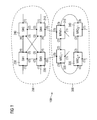
- the office network 200 comprises four network switches ("switches”) 210, 220, 230, 240, which are located in FIG. 1 marked with SW1 to SW4. Each of these switches 210, 220, 230, 240 comprises a plurality of interfaces ("ports") that are integrated in FIG. 1 at each of the switches 210, 220, 230, 240 are numbered. This means that each port of a switch 210, 220, 230, 240 can be uniquely assigned and defined by specifying the switch and the number of the port.
- the four switches 210, 220, 230, 240 are over network lines between their ports to the office network 200 which is an example of a first subnet in the sense of the present description.
- Each of the switches SW1 to SW4 has an external interface, which is identified at each of the switches SW1 to SW4 with the number (1).
- telecommunication terminals such as computers, telephones, automation modems or even other communication networks can be connected to a respective switch via these external interfaces.
- the ports of the switches SW3 220 and SW4 210 of the office network 200 designated by the serial number (5) are also external interfaces of the office network 200, via which the connection to the industrial network 300 is established accordingly.
- An STP or RSTP protocol is installed on the first subnetwork 200 with which, for example, transport loops or redundant communication paths can be avoided.
- transport loops or redundant communication paths For example, for a message sent from the switch SW2 240 to the switch SW3 220, there are various transmission paths, of which only one is selected in the context of the STP or RSTP protocol and the others are shut down by setting the states of the individual ports of the various switches .
- these port states are then adapted in accordance with the STP or RSTP protocol in such a way that clear and, in particular, loop-free communication paths within the network are again present.
- the switch SW1 230 can take over the function of the "root bridge" for the STP or RSTP protocol.
- the industrial network 300 also has four switches 310, 320, 330, 340 connected in a ring structure. In this case, the formation of the ring takes place via a connection of the ports labeled in each case with "2" and "3" of the switches 310, 320, 330, 340 of the industrial network 300.
- MRP Media Redundancy Protocol
- MRM Media Redundancy Manager
- the switches 310, 320, 330, 340 of the industrial network 300 also have external interfaces, which are each designated by the number "1".
- the ports numbered (5) of the switches 310 and 320 are also external interfaces of the industrial network 300, whereby the connection to the office network 200 takes place via these interfaces.
- switches 310, 320, 330, 340 of the industrial network 300 are also integrated into the STP or RSTP protocol of the office network.
- the MRM 310 in the industrial network 300 is designed in such a way that the industrial network 300 from the STP or RSTP protocol of the office network 200 is regarded by it as a virtual network node.
- This additional functionality is indicated by the "+" at the MRM FIG. 1 symbolizes.
- the industrial network 300 appears as part of the RSTP or STP protocol Virtual network node with the current numbers (1) and (5) designated external interfaces as external interfaces of the virtual network node.
- the internal structure of the industrial network 300 plays no or only a minor role within the framework of the RSTP or STP protocol, since this knowledge and the corresponding information distribution and forwarding is taken over by the MRM + 310 within the industrial network 300.
- the MRC nodes 320, 330, 340 in the industrial network support this coordinating function of the MRM + in the context of the RSTP or STP protocol by being able to capture, understand and answer corresponding information, query or instruction messages from the MRM +.
- This property of MRC nodes 320, 330, 340 is indicated by an additional "+" in the label in FIG FIG. 1 symbolizes.
- the MRM + 310 may send polling messages to all of the MRC nodes 320, 330, 340, with the request to return the respective external interfaces and possibly also internal interfaces to the MRM +. Then, for example, the MRM + 310 can assign to the individual external interfaces in the industrial network 300 unique port identification data, so that each external interface in the industrial network 300 can be clearly addressed by the STP or RSTP protocol. This port identification data is then sent back to the individual MRC nodes 320, 330, 340, so that each switch 310, 320, 330, 340 in the industrial network 300 knows about the identification data of its ports. Furthermore, the MRM + 310 has complete information about which of the ports are on which of the switches 310, 320, 330, 340.
- This configuration has the advantage that the very fast reconfiguration time of the MRP protocol in the industrial network 300 in case of faults in the industrial network 300 through the RSTP or STP protocol is not affected because the internal structure of the industrial network 300 for the STP or RSTP protocol of the office network 200 is not visible.
- Reconfiguration in the industrial network 300 by the MRM + 310 affects the communication paths within the industrial network 300, but not its external interfaces and thus its appearance to the STP or RSTP protocol.
- the STP or RSTP protocol had to be implemented in each of the network nodes 310, 320, 330, 340 of the industrial network in order to be able to couple the office network 200 to the industrial network 300.
- the complete communication network 100 consisting of the office network 200 and the industrial network 300, then has to be completely reconfigured by the STP or RSTP protocol, which in some cases takes considerable time can and in this time the industrial network 300 impaired or even paralyzed. Particularly in the case where the industrial network 300 is used in automation or control, such downtime is often not tolerable.
- FIG. 2 is that in FIG. 1 illustrated communication system 100 shown in a slightly modified form.
- the MRC client MRC 1 + 320 was replaced by a "reserve master" MRM 2 + 312. All other network components of the communication network 100 correspond in designation and execution those in FIG. 1 shown.
- the reserve master 312 of the industrial network 300 has the task to take over the functionality of the MRM + 310, if this occurs a malfunction. Such a malfunction may include, for example, a complete failure of the MRM + or an error in the program flow or at its interfaces.
- the MRM 2 +312 is designed such that it fulfills both the role of the MRP master of the MRM + 310 and the role as spanning tree main node for the industrial network 300 from the MRM +.
- the MRM 2 + only takes on one of the two functionalities, eg in the case when the malfunction of the MRM + concerns only one of the two functionalities.
- the MRM + transmits, at least then, the information about the network configuration of the industrial network 300, the corresponding portstates and / or the port identification data of the network nodes 310, 320, 330, 340 of the switches in the communication network 300, if this information is used something has changed or changed.
- the MRM 2+ always has the most up-to-date information about the state of the industrial network 300, so that it can take over the above-mentioned activity from the MRM + at any time.
- the assumption of the above-mentioned task of the MRM + by the MRM 2 + can, for example, take place if the MRM 2 + does not receive any messages from the MRM + over a predetermined period of time and can therefore assume its failure. Furthermore, the assumption of these tasks can also take place when the MRM 2 + receives a corresponding message or information, for example from the MRM + or another network node.
- the MRM 2 + can also perform this functionality from the MRM +.
- this acquisition can be designed such that the MRM 2 + directly takes over the root bridge data of the MRM +, including the corresponding identification data.
- the industry network 300 appears as a virtual, unmodified root bridge for the office network 200 STP or RSTP protocol.
- the MRM 2 + 312 may use other identification data than that of the MRM +, eg, retain its previous identification data.
- replacement by MRM 2 + may then involve further reconfiguration steps of the STP or RSTP protocol of the office network 200.
- the following is another exemplary embodiment of the present invention, involving the coupling of an annular communication network implementing a Media Redundancy Protocol (MRP) protocol (hereafter referred to as MRP ring) to an Ethernet network on which the RSTP Protocol is implemented (hereinafter referred to as RSTP network).
- MRP Media Redundancy Protocol
- RSTP network for example, the office network 200 in the FIGS. 1 and 2 while the MRP ring, for example, the industrial network 300 in the FIGS. 1 and 2 can correspond.
- MRP ring can be extended to any ring and / or line networks, while the following comments on the RSTP network on STP and / or MSTP networks and all communication networks with a spanning tree protocol according to the present Expand description.
- the MRP ring is an example of a second subnet and / or communication subnet according to the present description, while the RSTP network is an example of a first subnet according to the present description.
- efficient coupling of MRP rings with RSTP networks is achieved by the following mechanisms.
- the MRP and RSTP decisions must be coordinated to compute the port states of the network nodes such that a valid MRP and RSTP network is formed, e.g. A line topology for the MRP and a tree topology for the RSTP network.
- a valid MRP and RSTP network is formed, e.g. A line topology for the MRP and a tree topology for the RSTP network.
- One approach is to have the entire MRP ring appear as a single virtual RSTP hub in an outside view. Therefore, all MRP ring nodes connected to the RSTP network via external ports should send Bridge Protocol Data Units (BPDUs) with the same bridge identification.
- BPDUs Bridge Protocol Data Units
- External ports are non-ring ports in the example of a ring topology. In a line topology, ring ports that are not associated with other ring ports are treated as external ports.
- each of the external ports must be assigned a unique port ID in the MRP network, even if the external ports are located on physically different switches.
- a virtual bridge formed by the MRP ring as described above, for example, can also act as a root bridge for the RSTP network.
- one of the ring nodes may be responsible for sending BPDUs to all other RSTP-enabled network nodes of the MRP ring and receiving all BPDUs from them, this central bridge also including the port states of all external RSTP ports in the MRP ring. Ring calculated and signaled within the ring.
- This central bridge in the MRP ring is an example of a spanning tree main node in the sense of the present description.
- the port state calculation is done locally on all RSTP-capable nodes in the MRP ring, with the corresponding information being exchanged between these nodes so that each of the nodes has the same consistent view of the entire network.
- the central node in the MRP-Ring which is responsible for the RSTP functionality of the MRP-Rin g s as a virtual bridge, will be called MRM + hereinafter. All other ring nodes connected to external devices via external ports will only forward RSTP BPDUs coming from the MRM + outward and vice versa.
- the other network nodes in the MRP ring are called MRC + because they support the RSTP functionality of the MRM +.
- the MRM + is an example of this in the context of the FIGS. 1 and 2 discussed MRM + as well as a spanning tree main node in the sense of the present description.
- the MRC + can, for example, the MRC + in the FIGS. 1 and 2 and is further an example of a spanning tree subnode according to the present description.
- the BPDUs are tunneled (eg by being encapsulated in manufacturer-specific MRP frames). If the MRC + are RSTP enabled then this RSTP functionality must be turned off. The only RSTP functionality that is executed in the MRC + is to clear learned addresses in the "forwarding table", if necessary because of port state changes and initiated by the MRM +.
- This solution also allows to use pure MRC nodes that do not have extensions to handle RSTP functionalities within the ring. However, such nodes must not be connected to the external RSTP network via external ports. If so, conflicts between MRP protocol and RSTP protocol would occur. However, most of the pure MRC nodes used in the automation environment are two port nodes, which are not affected by such a disadvantage.
- Every change in the MRP ring that is visible in the RSTP network results in a new calculation of the spanning tree. Examples include changes in the identification data of network nodes or interfaces of network nodes by the connection of new nodes or ring segments with the existing MRP ring or even failures in the ring, especially a failure of the MRM +. Since RSTP has considerably longer reconfiguration times than MRP (eg, a few seconds for RSTP compared to a few tenths or hundredths of a second for MRP), and because the connections between the RSTP node part are partially lost during reconfiguration, these are described by the ones described herein Design options Changes that are visible to the outside in the RSTP network are avoided or minimized wherever possible. Therefore, the MRP ring should be in a steady state before taking up the activity as an RSTP virtual network node.
- the MRC + network nodes should keep their external ports in the "blocking" state during start up of the MRP ring. Sending out RSTP BPDUs at this stage would rather lead to disturbing information within the RSTP network and unnecessarily complicate and extend its start-up or reconfiguration.
- the MRP ring Before the MRP ring takes up its functionality as a virtual node, it must configure itself. For this purpose, a single network node within the ring is selected as MRM + and all other network nodes in the ring are set as MRC + or ordinary MRC nodes. As described above, the MRM + calculates the "RSTP state machine". For this he needs information about the MRC + network nodes, which are installed in the MRP-Ring and their properties like their addresses, local port indices, local port priorities, and the port path cost of the external ports. In addition to these local MRC + port information, the MRM + can also collect neighborhood information regarding the ring ports of all MRC + nodes in the ring.
- the MRM + sends a corresponding request to all MRC + network nodes and they send back a corresponding response message. Thereafter, the MRM + calculates unique port IDs consisting of a priority and an index for each port of each network node. To initialize the MRP ring as a virtual bridge, this information is sent from the MRM + to each MRC + with external interfaces.
- the same telegrams are also used to detect or cause corresponding changes in the port states.
- the MRM + generates BPDUs which are tunnelled to the ring network nodes, which then send them via the external RSTP ports and vice versa.
- the MRM detects topology changes based on BPDU information and BPDU "Timeout Monitoring" as usual in RSTP.
- the MRC + create and tunnel BPDUs on the MRM + in case of connection changes on their external interfaces.
- the MRM + opens its blocked port, whereupon, in the worst case, the MRP ring is again fully functional after eg a few tenths or hundredths of a second. Since the default setting of the "RSTP-Hellotime" is two seconds and two repetitions are allowed, such a change in the MRP-ring does not cause any reconfiguration in the RSTP network. For example, in order to be able to react meaningfully to a failure of the MRM +, a replacement MRM + can already be determined in anticipation.
- the active MRM + what this replacement MRM + (also MRM 2 +) from the MRM + all necessary information is obtained, such as bridge ID, port IDs and MRM priorities of all MRM + -RingKnoten.
- the active MRM + informs the replacement MRM + of its role as a replacement MRM + and always provides it with the current RSTP information. In this way, the replacement MRM is always able to assume the role of MRM + without significant consequences for the RSTP network (except for the ports of the failed MRM +).
- the new MRM + can use the existing bridge ID of the virtual RSTP node instead of its own original bridge ID as the RSTP node.
- This MRM + redundancy concept helps to eliminate or at least reduce one of the most disturbing disadvantages of RSTP: The comparatively very long reconfiguration time after a root bridge failure.
- the virtual bridge formed by the MRP ring is selected as the "root bridge", which can be easily achieved by assigning a correspondingly small bridge ID, a redundant root bridge can be obtained in this way.
- the replacement MRM + or MRM 2 + according to the present example is an example of an MRM 2 +, as in connection with the FIGS. 1 and 2 and is also an example of a spanning tree reserve main node according to the present description.
- One approach in this case may be for the repaired MRM + to wait a certain amount of time after installation before sending out its RSTP BPDUs. During this waiting period, he receives RSTP BPDUs from one or more neighboring nodes, from which he can also recognize the current ID of the current root bridge. In this way, the repaired MRM + recognizes that its ID already exists on the network and stops the automatic "start-up" process. Thereafter, a corresponding diagnostic and correction run can be made to eliminate this problem.
- Another alternative for dealing with this problem is that it is intended to exchange the IDs of the MRM + and the replacement MRM + in case of error. Both the MRM + and the replacement MRM + always know both the IDs. If the active MRM + fails, then the replacement MRM + takes over the original MRM + ID. Furthermore, the MRM + is configured to recognize when restarting from this stored data that it must boot up with the ID of the original MRM + replacement. In this way, the MRM + and the replacement MRM + have swapped roles and there are no duplicate bridge IDs in the network.
- the first subnet according to the present description may also have a line structure and / or a ring structure. Furthermore, it can be provided in this case that the first subnetwork is treated by the spanning tree protocol of the second subnetwork as a virtual network node or is treatable. In this case, the first subnet may also have the features of a second subnet or communication subnet according to the present description.
- both the first and the second subnetwork may have a ring structure, with each of the rings for the other ring appearing as a virtual network node.
- you can two neighboring subnets with a ring structure act as two virtual network nodes and use the fast local RSTP switchover: If the "root port" of a virtual network node fails, it is possible to switch to an "alternate port" of this virtual network node previously calculated by the spanning tree protocol , in the event of a "Designated Port” failure on a corresponding "Backup Port".
- This case is particularly advantageously applicable in a configuration in which adjacent ring networks are linked via at least two redundant links. In this case, the interference in one of the connections can be handled locally by the RSTP switching process, resulting in a fast recovery or reconfiguration of the coupled network rings.
- the present invention describes a communication network composed of multiple subnetworks, wherein at least one of the networks implements a spanning tree protocol for avoiding transport loops and redundant paths, and wherein at least one of the subnetworks is handled by the spanning tree protocol as a virtual network node and is treatable.
- reconfigurations can be decoupled or substantially decoupled according to the spanning tree protocol and within a subnetwork that appears as a virtual network node, thus speeding up and simplifying reconfigurations, for example.
Landscapes
- Engineering & Computer Science (AREA)
- Computer Networks & Wireless Communication (AREA)
- Signal Processing (AREA)
- Small-Scale Networks (AREA)
Priority Applications (4)
| Application Number | Priority Date | Filing Date | Title |
|---|---|---|---|
| EP10000124.7A EP2343857B1 (fr) | 2010-01-08 | 2010-01-08 | Noeud de réseau pour un réseau de communication |
| ES10000124.7T ES2656433T3 (es) | 2010-01-08 | 2010-01-08 | Nodo de red para una red de comunicaciones |
| US12/986,786 US9385885B2 (en) | 2010-01-08 | 2011-01-07 | Network node for a communication network having a first subnetwork using a spanning tree protocol and a second subnetwork connected to the first subnetwork |
| CN201110003150.4A CN102123081B (zh) | 2010-01-08 | 2011-01-07 | 用于通信网络的网络节点 |
Applications Claiming Priority (1)
| Application Number | Priority Date | Filing Date | Title |
|---|---|---|---|
| EP10000124.7A EP2343857B1 (fr) | 2010-01-08 | 2010-01-08 | Noeud de réseau pour un réseau de communication |
Publications (2)
| Publication Number | Publication Date |
|---|---|
| EP2343857A1 true EP2343857A1 (fr) | 2011-07-13 |
| EP2343857B1 EP2343857B1 (fr) | 2017-10-18 |
Family
ID=42290132
Family Applications (1)
| Application Number | Title | Priority Date | Filing Date |
|---|---|---|---|
| EP10000124.7A Active EP2343857B1 (fr) | 2010-01-08 | 2010-01-08 | Noeud de réseau pour un réseau de communication |
Country Status (4)
| Country | Link |
|---|---|
| US (1) | US9385885B2 (fr) |
| EP (1) | EP2343857B1 (fr) |
| CN (1) | CN102123081B (fr) |
| ES (1) | ES2656433T3 (fr) |
Cited By (13)
| Publication number | Priority date | Publication date | Assignee | Title |
|---|---|---|---|---|
| DE102011003325A1 (de) * | 2011-01-28 | 2012-08-02 | Siemens Aktiengesellschaft | Automatisierungsnetzwerk mit zumindest einem virtuellen privaten Teilnetzwerk |
| EP2562960A1 (fr) * | 2011-08-23 | 2013-02-27 | Siemens Aktiengesellschaft | Procédé de transmission de données redondant dans un réseau de communication |
| EP2634973A1 (fr) | 2012-02-29 | 2013-09-04 | Siemens Aktiengesellschaft | Appareil de communication pour un réseau de communication industriel fonctionnant de manière redondante et procédé de fonctionnement d'un appareil de communication |
| EP2661023A1 (fr) | 2012-04-30 | 2013-11-06 | Siemens Aktiengesellschaft | Appareil de communication pour un réseau de communication industriel fonctionnant de manière redondante et procédé de fonctionnement d'un appareil de communication |
| CN103428805A (zh) * | 2013-08-07 | 2013-12-04 | 湖南大学 | 一种基于链路抗干扰性的无线网络虚拟化映射方法 |
| EP2688249A1 (fr) | 2012-07-20 | 2014-01-22 | Siemens Aktiengesellschaft | Procédé de transmission de nouvelles dans un réseau de communication industriel pouvant fonctionner de manière redondante et appareil de communication pour un réseau de communication industriel pouvant fonctionner de manière redondante |
| EP2693700A1 (fr) | 2012-07-31 | 2014-02-05 | Siemens Aktiengesellschaft | Procédé de transmission de messages dans un réseau de communication industriel pouvant fonctionner de manière redondante et appareil de communication pour un réseau de communication industriel pouvant fonctionner de manière redondante |
| EP2704370A1 (fr) | 2012-08-31 | 2014-03-05 | Siemens Aktiengesellschaft | Procédé de transmission de nouvelles dans un réseau de communication industriel pouvant fonctionner de manière redondante et appareil de communication pour un réseau de communication industriel pouvant fonctionner de manière redondante |
| EP2713563A1 (fr) | 2012-09-28 | 2014-04-02 | Siemens Aktiengesellschaft | Système de communication industriel pouvant fonctionner de manière redondante, appareil de communication et procédé de fonctionnement redondant d'un système de communication industriel |
| WO2014072374A1 (fr) | 2012-11-09 | 2014-05-15 | Siemens Aktiengesellschaft | Procédé de transmission de messages dans un réseau de communication industriel d'un système d'automatisation industriel et dispositif de communication d'un réseau de communication industriel |
| EP2750340A1 (fr) | 2012-12-28 | 2014-07-02 | Siemens Aktiengesellschaft | Procédé de transmission de nouvelles dans un réseau de communication industriel à fonctionnement redondant et appareil d'infrastructure de réseau |
| EP2750310A1 (fr) | 2012-12-28 | 2014-07-02 | Siemens Aktiengesellschaft | Procédé de synchronisation d'horloges locales dans un réseau de communication d'un système d'automatisation industriel et appareil d'infrastructure de réseau |
| DE112012005949B4 (de) * | 2012-02-27 | 2016-01-28 | Kyland Technology Co., Ltd | Verfahren zur Verwirklichung eines redundanten Netzwerkes |
Families Citing this family (21)
| Publication number | Priority date | Publication date | Assignee | Title |
|---|---|---|---|---|
| US9160564B2 (en) * | 2012-06-25 | 2015-10-13 | Qualcomm Incorporated | Spanning tree protocol for hybrid networks |
| CN102724096B (zh) * | 2012-06-26 | 2014-12-17 | 华为技术有限公司 | 混合环网保护方法和网络设备 |
| GB2524749B (en) * | 2014-03-31 | 2018-12-19 | Metaswitch Networks Ltd | Spanning tree protocol |
| CN105939204B (zh) * | 2015-08-24 | 2019-04-09 | 杭州迪普科技股份有限公司 | 多协议协同操作接口状态方法以及装置 |
| US9843495B2 (en) * | 2015-08-26 | 2017-12-12 | Fujitsu Limited | Seamless migration from rapid spanning tree protocol to ethernet ring protection switching protocol |
| US10156841B2 (en) | 2015-12-31 | 2018-12-18 | General Electric Company | Identity management and device enrollment in a cloud service |
| KR20180028291A (ko) * | 2016-09-08 | 2018-03-16 | 한국전기연구원 | 이더넷 프레임 기반의 트래픽 제어 방법 |
| US9923731B1 (en) | 2016-09-12 | 2018-03-20 | Fujitsu Limited | Seamless migration from multiple spanning tree protocol to ethernet ring protection switching protocol |
| US10411984B2 (en) * | 2016-12-12 | 2019-09-10 | Johnson Controls Technology Company | Systems and methods related to diagnostics for ethernet rings based on media redundancy protocol |
| US11277279B2 (en) * | 2016-12-12 | 2022-03-15 | Johnson Controls Tyco IP Holdings LLP | Systems and methods for incorporating a single-port ethernet device in a media protocol ring |
| US11025537B2 (en) * | 2017-12-04 | 2021-06-01 | Is5 Communications, Inc. | Multiple RSTP domain separation |
| US11265239B1 (en) | 2019-09-10 | 2022-03-01 | Cisco Technology, Inc. | Extended network node provisioning in software defined access fabric networks |
| US11252073B1 (en) * | 2020-01-24 | 2022-02-15 | Cisco Technology, Inc. | Fast, reliable, and extensible active-standby multi-vendor link redundancy |
| US11240167B2 (en) * | 2020-06-29 | 2022-02-01 | Lenovo Enterprise Solutions (Singapore) Pte. Ltd. | Energy efficient optimization for spanning tree protocol |
| CN116320589A (zh) * | 2021-12-21 | 2023-06-23 | 北京小米移动软件有限公司 | 投屏控制方法、数据发送装置、数据接收装置及存储介质 |
| CN114553322B (zh) * | 2022-01-30 | 2024-03-15 | 西北工业大学 | 一种低开销的水声网络去中心化方法 |
| US12579011B1 (en) | 2023-02-27 | 2026-03-17 | Nvidia Corporation | Application programming interface to indicate semaphore wait dependencies |
| US12511106B1 (en) | 2023-02-27 | 2025-12-30 | Nvidia Corporation | Application programming interface to indicate host dependencies |
| US12602230B1 (en) | 2023-02-27 | 2026-04-14 | Nvidia Corporation | Application programming interface to indicate null-operation dependencies |
| EP4425875A1 (fr) | 2023-02-28 | 2024-09-04 | Siemens Aktiengesellschaft | Procédé de transmission de données à haute disponibilité dans un système de communication, système de communication et appareil de communication |
| EP4718786A1 (fr) | 2024-09-25 | 2026-04-01 | Siemens Aktiengesellschaft | Procédé de transmission redondante de données dans un réseau de communication, système de communication et dispositif de configuration |
Citations (1)
| Publication number | Priority date | Publication date | Assignee | Title |
|---|---|---|---|---|
| WO2008119626A2 (fr) | 2007-03-30 | 2008-10-09 | Siemens Aktiengesellschaft | Procédé de reconfiguration d'un réseau de communication |
Family Cites Families (15)
| Publication number | Priority date | Publication date | Assignee | Title |
|---|---|---|---|---|
| US6304575B1 (en) * | 1998-08-31 | 2001-10-16 | Cisco Technology, Inc. | Token ring spanning tree protocol |
| US7209435B1 (en) * | 2002-04-16 | 2007-04-24 | Foundry Networks, Inc. | System and method for providing network route redundancy across Layer 2 devices |
| US7463597B1 (en) * | 2004-08-27 | 2008-12-09 | Juniper Networks, Inc. | Spanning tree protocol synchronization within virtual private networks |
| CN100417118C (zh) * | 2005-10-28 | 2008-09-03 | 华为技术有限公司 | 一种无线网状网中网络移动节点的位置更新系统和方法 |
| US7936702B2 (en) * | 2005-12-01 | 2011-05-03 | Cisco Technology, Inc. | Interdomain bi-directional protocol independent multicast |
| US7944853B2 (en) * | 2006-01-06 | 2011-05-17 | Belair Networks Inc. | Virtual root bridge |
| DE102007015539B4 (de) * | 2007-03-30 | 2012-01-05 | Siemens Ag | Verfahren zum Rekonfigurieren eines Kommunikationsnetzwerks |
| US7835297B2 (en) | 2007-06-29 | 2010-11-16 | World Wide Packets, Inc. | Determining the state of a tunnel with respect to a control protocol |
| US7864712B2 (en) * | 2007-07-20 | 2011-01-04 | Cisco Technology, Inc. | Preventing loops in networks operating different protocols to provide loop-free topology |
| EP2043306B1 (fr) | 2007-09-28 | 2015-04-15 | Unify GmbH & Co. KG | Procédé destiné à l'organisation de noeuds dans un réseau orienté paquet |
| US8305938B2 (en) * | 2007-12-31 | 2012-11-06 | Ciena Corporation | Interworking an ethernet ring network with a spanning tree controlled ethernet network |
| KR101421145B1 (ko) * | 2008-01-09 | 2014-07-18 | 삼성전자주식회사 | 무선 메쉬 네트워크에서 게이트웨이 선택 방법 |
| WO2010105828A1 (fr) * | 2009-03-18 | 2010-09-23 | Hirschmann Automation And Control Gmbh | Exploitation en parallèle de protocoles rstp (rapid spanning tree protocol) et mrp (media redundancy protocol) et segmentation/couplage |
| US8355348B1 (en) * | 2009-08-17 | 2013-01-15 | Calix, Inc. | Joining multiple spanning tree networks across ring network |
| US20110134802A1 (en) * | 2009-12-09 | 2011-06-09 | Cisco Technology, Inc. | Determining A Routing Tree For Networks With Different Routing Protocols |
-
2010
- 2010-01-08 EP EP10000124.7A patent/EP2343857B1/fr active Active
- 2010-01-08 ES ES10000124.7T patent/ES2656433T3/es active Active
-
2011
- 2011-01-07 CN CN201110003150.4A patent/CN102123081B/zh active Active
- 2011-01-07 US US12/986,786 patent/US9385885B2/en active Active
Patent Citations (1)
| Publication number | Priority date | Publication date | Assignee | Title |
|---|---|---|---|---|
| WO2008119626A2 (fr) | 2007-03-30 | 2008-10-09 | Siemens Aktiengesellschaft | Procédé de reconfiguration d'un réseau de communication |
Non-Patent Citations (3)
| Title |
|---|
| "IEEE Standards for Local and Metropolitan Area Networks--- Virtual Bridged Local Area Networks--- Amendment 3: Multiple Spanning Trees;IEEE Std 802.1s-2002 (Amendment to IEEE Std 802.1Q, 1998 Edition) ED - Anonymous", IEEE STANDARD; [IEEE STANDARD], IEEE, PISCATAWAY, NJ, USA, 1 January 2002 (2002-01-01), pages _1 - 211, XP017603570, ISBN: 978-0-7381-3495-6 * |
| CISCO SYSTEMS ET AL: "Understanding Multiple Spanning Tree Protocol (802.1s)", INTERNET CITATION, 14 May 2005 (2005-05-14), XP002426379, Retrieved from the Internet <URL:http://web.archive.org/web/20050514065955/www.cisco.com/warp/public/4 73/147.pdf> [retrieved on 20070323] * |
| KLEINEBERG O ET AL: "Automatic device configuration for Ethernet ring redundancy protocols", EMERGING TECHNOLOGIES&FACTORY AUTOMATION, 2009. ETFA 2009. IEEE CONFERENCE ON, IEEE, PISCATAWAY, NJ, USA, 22 September 2009 (2009-09-22), pages 1 - 8, XP031575608, ISBN: 978-1-4244-2727-7 * |
Cited By (20)
| Publication number | Priority date | Publication date | Assignee | Title |
|---|---|---|---|---|
| DE102011003325A1 (de) * | 2011-01-28 | 2012-08-02 | Siemens Aktiengesellschaft | Automatisierungsnetzwerk mit zumindest einem virtuellen privaten Teilnetzwerk |
| EP2562960A1 (fr) * | 2011-08-23 | 2013-02-27 | Siemens Aktiengesellschaft | Procédé de transmission de données redondant dans un réseau de communication |
| DE112012005949B4 (de) * | 2012-02-27 | 2016-01-28 | Kyland Technology Co., Ltd | Verfahren zur Verwirklichung eines redundanten Netzwerkes |
| EP2634973A1 (fr) | 2012-02-29 | 2013-09-04 | Siemens Aktiengesellschaft | Appareil de communication pour un réseau de communication industriel fonctionnant de manière redondante et procédé de fonctionnement d'un appareil de communication |
| US9356830B2 (en) | 2012-02-29 | 2016-05-31 | Siemens Aktiengesellschaft | Communication device for a redundantly operable industrial communication network and method for operating the communication device |
| US9166922B2 (en) | 2012-04-30 | 2015-10-20 | Siemens Aktiengesellschaft | Communication device for an industrial communication network which can be operated in a redundant manner and method for operating a communication device |
| EP2661023A1 (fr) | 2012-04-30 | 2013-11-06 | Siemens Aktiengesellschaft | Appareil de communication pour un réseau de communication industriel fonctionnant de manière redondante et procédé de fonctionnement d'un appareil de communication |
| RU2625935C2 (ru) * | 2012-04-30 | 2017-07-19 | Сименс Акциенгезелльшафт | Устройство связи для эксплуатируемой с избыточностью промышленной сети связи и способ эксплуатации устройства связи |
| EP2688249A1 (fr) | 2012-07-20 | 2014-01-22 | Siemens Aktiengesellschaft | Procédé de transmission de nouvelles dans un réseau de communication industriel pouvant fonctionner de manière redondante et appareil de communication pour un réseau de communication industriel pouvant fonctionner de manière redondante |
| US9413609B2 (en) | 2012-07-20 | 2016-08-09 | Siemens Aktiengesellschaft | Communication device and method for transmitting messages in a redundantly operable industrial communication network |
| US9218230B2 (en) | 2012-07-31 | 2015-12-22 | Siemens Aktiengesellschaft | Method for transmitting messages in a redundantly operable industrial communication network and communication device for the redundantly operable industrial communication network |
| EP2693700A1 (fr) | 2012-07-31 | 2014-02-05 | Siemens Aktiengesellschaft | Procédé de transmission de messages dans un réseau de communication industriel pouvant fonctionner de manière redondante et appareil de communication pour un réseau de communication industriel pouvant fonctionner de manière redondante |
| EP2704370A1 (fr) | 2012-08-31 | 2014-03-05 | Siemens Aktiengesellschaft | Procédé de transmission de nouvelles dans un réseau de communication industriel pouvant fonctionner de manière redondante et appareil de communication pour un réseau de communication industriel pouvant fonctionner de manière redondante |
| EP2713563A1 (fr) | 2012-09-28 | 2014-04-02 | Siemens Aktiengesellschaft | Système de communication industriel pouvant fonctionner de manière redondante, appareil de communication et procédé de fonctionnement redondant d'un système de communication industriel |
| US10044580B2 (en) | 2012-09-28 | 2018-08-07 | Siemens Aktiengesellschaft | Redundantly operable industrial communication system, communication device and method for redundantly operating an industrial communication system |
| WO2014072374A1 (fr) | 2012-11-09 | 2014-05-15 | Siemens Aktiengesellschaft | Procédé de transmission de messages dans un réseau de communication industriel d'un système d'automatisation industriel et dispositif de communication d'un réseau de communication industriel |
| EP2750340A1 (fr) | 2012-12-28 | 2014-07-02 | Siemens Aktiengesellschaft | Procédé de transmission de nouvelles dans un réseau de communication industriel à fonctionnement redondant et appareil d'infrastructure de réseau |
| EP2750310A1 (fr) | 2012-12-28 | 2014-07-02 | Siemens Aktiengesellschaft | Procédé de synchronisation d'horloges locales dans un réseau de communication d'un système d'automatisation industriel et appareil d'infrastructure de réseau |
| CN103428805B (zh) * | 2013-08-07 | 2016-01-20 | 湖南大学 | 一种基于链路抗干扰性的无线网络虚拟化映射方法 |
| CN103428805A (zh) * | 2013-08-07 | 2013-12-04 | 湖南大学 | 一种基于链路抗干扰性的无线网络虚拟化映射方法 |
Also Published As
| Publication number | Publication date |
|---|---|
| CN102123081B (zh) | 2015-07-01 |
| US20120008530A1 (en) | 2012-01-12 |
| ES2656433T3 (es) | 2018-02-27 |
| US9385885B2 (en) | 2016-07-05 |
| CN102123081A (zh) | 2011-07-13 |
| EP2343857B1 (fr) | 2017-10-18 |
Similar Documents
| Publication | Publication Date | Title |
|---|---|---|
| EP2343857B1 (fr) | Noeud de réseau pour un réseau de communication | |
| EP2070256B1 (fr) | Procédé pour reconfigurer un réseau de communication | |
| EP2838220B1 (fr) | Procédé de transmission redondante de messages dans un réseau de communication industriel et appareil de communication | |
| DE102007015539B4 (de) | Verfahren zum Rekonfigurieren eines Kommunikationsnetzwerks | |
| EP2693700B1 (fr) | Procédé de transmission de messages dans un réseau de communication industriel pouvant fonctionner de manière redondante et appareil de communication pour un réseau de communication industriel pouvant fonctionner de manière redondante | |
| EP2721784B1 (fr) | Procédé de fonctionnement d' un équipement de réseau et équipement de réseau | |
| WO2010105828A1 (fr) | Exploitation en parallèle de protocoles rstp (rapid spanning tree protocol) et mrp (media redundancy protocol) et segmentation/couplage | |
| EP2713563B1 (fr) | Système de communication industriel pouvant fonctionner de manière redondante, appareil de communication et procédé de fonctionnement redondant d'un système de communication industriel | |
| EP1532771A1 (fr) | Methode d'essai de chemins de messages dans des reseaux de communication et element de reseau | |
| EP3787237B1 (fr) | Procédé de transmission de données dans un réseau de communication à fonctionnement redondant et appareil de communication par couplage | |
| EP3151476B1 (fr) | Procede de trafic transversal entre deux esclaves d'un reseau de donnees en boucle | |
| EP1955480B1 (fr) | Réseau ayant des propriétés de redondance, commutateur ethernet pour un réseau de ce type et procédé de configuration d un réseau de ce type | |
| EP2130331B1 (fr) | Procédé de reconfiguration d'un réseau de communication | |
| EP2704370B1 (fr) | Procédé de transmission de nouvelles dans un réseau de communication industriel pouvant fonctionner de manière redondante et appareil de communication pour un réseau de communication industriel pouvant fonctionner de manière redondante | |
| EP2127241B1 (fr) | Recherche de port cible dans des réseaux constitués de sous-réseaux reliés | |
| EP4125253B1 (fr) | Procédé de transmission de données temporellement critiques, système de communication et appareil de communication couplée | |
| WO2015014543A1 (fr) | Protocole de redondance logiciel | |
| EP2720408B1 (fr) | Procédé et appareil de transmission de données pour la transmission de données au sein d'un système de transmission de données xDSL | |
| EP2750310A1 (fr) | Procédé de synchronisation d'horloges locales dans un réseau de communication d'un système d'automatisation industriel et appareil d'infrastructure de réseau | |
| EP2182680B1 (fr) | Procédé destiné au fonctionnement d'un réseau de communication et composants de communication | |
| EP2817923B1 (fr) | Réseau de calculateurs avec un bus de liaison de forme annulaire | |
| DE102007021922B4 (de) | Paketvermitteltes Kommunikationsnetzwerk und Verfahren zum Rekonfigurieren des Kommunikationsnetzwerks | |
| EP2721771A2 (fr) | Procédé d'interconnexion redondante et à faibles perturbations de réseaux de communication à l'aide du protocole d'arbre couvrant rapide rstp (rapid spanning tree) | |
| EP2290882A1 (fr) | Procédé de redondance d'erreurs multiple dans des réseaux à topologies annulaires | |
| EP2750340A1 (fr) | Procédé de transmission de nouvelles dans un réseau de communication industriel à fonctionnement redondant et appareil d'infrastructure de réseau |
Legal Events
| Date | Code | Title | Description |
|---|---|---|---|
| PUAI | Public reference made under article 153(3) epc to a published international application that has entered the european phase |
Free format text: ORIGINAL CODE: 0009012 |
|
| AK | Designated contracting states |
Kind code of ref document: A1 Designated state(s): AT BE BG CH CY CZ DE DK EE ES FI FR GB GR HR HU IE IS IT LI LT LU LV MC MK MT NL NO PL PT RO SE SI SK SM TR |
|
| AX | Request for extension of the european patent |
Extension state: AL BA RS |
|
| 17P | Request for examination filed |
Effective date: 20110808 |
|
| 17Q | First examination report despatched |
Effective date: 20120301 |
|
| RAP1 | Party data changed (applicant data changed or rights of an application transferred) |
Owner name: SIEMENS AKTIENGESELLSCHAFT |
|
| REG | Reference to a national code |
Ref country code: DE Ref legal event code: R079 Ref document number: 502010014258 Country of ref document: DE Free format text: PREVIOUS MAIN CLASS: H04L0012420000 Ipc: H04L0012753000 |
|
| GRAP | Despatch of communication of intention to grant a patent |
Free format text: ORIGINAL CODE: EPIDOSNIGR1 |
|
| RIC1 | Information provided on ipc code assigned before grant |
Ipc: H04L 12/46 20060101ALI20170412BHEP Ipc: H04L 12/753 20130101AFI20170412BHEP Ipc: H04L 12/42 20060101ALI20170412BHEP |
|
| INTG | Intention to grant announced |
Effective date: 20170516 |
|
| RIN1 | Information on inventor provided before grant (corrected) |
Inventor name: SCHEFFEL, MATTHIAS Inventor name: KULKARNI, VIVEK Inventor name: LOHMEYER, JOACHIM Inventor name: ZIRKLER, ANDREAS DR. |
|
| RAP1 | Party data changed (applicant data changed or rights of an application transferred) |
Owner name: SIEMENS AKTIENGESELLSCHAFT |
|
| GRAS | Grant fee paid |
Free format text: ORIGINAL CODE: EPIDOSNIGR3 |
|
| GRAA | (expected) grant |
Free format text: ORIGINAL CODE: 0009210 |
|
| AK | Designated contracting states |
Kind code of ref document: B1 Designated state(s): AT BE BG CH CY CZ DE DK EE ES FI FR GB GR HR HU IE IS IT LI LT LU LV MC MK MT NL NO PL PT RO SE SI SK SM TR |
|
| REG | Reference to a national code |
Ref country code: GB Ref legal event code: FG4D Free format text: NOT ENGLISH |
|
| REG | Reference to a national code |
Ref country code: CH Ref legal event code: EP |
|
| REG | Reference to a national code |
Ref country code: AT Ref legal event code: REF Ref document number: 938825 Country of ref document: AT Kind code of ref document: T Effective date: 20171115 Ref country code: IE Ref legal event code: FG4D Free format text: LANGUAGE OF EP DOCUMENT: GERMAN |
|
| REG | Reference to a national code |
Ref country code: DE Ref legal event code: R096 Ref document number: 502010014258 Country of ref document: DE |
|
| REG | Reference to a national code |
Ref country code: FR Ref legal event code: PLFP Year of fee payment: 9 |
|
| REG | Reference to a national code |
Ref country code: NL Ref legal event code: MP Effective date: 20171018 |
|
| REG | Reference to a national code |
Ref country code: ES Ref legal event code: FG2A Ref document number: 2656433 Country of ref document: ES Kind code of ref document: T3 Effective date: 20180227 |
|
| REG | Reference to a national code |
Ref country code: LT Ref legal event code: MG4D |
|
| PG25 | Lapsed in a contracting state [announced via postgrant information from national office to epo] |
Ref country code: NL Free format text: LAPSE BECAUSE OF FAILURE TO SUBMIT A TRANSLATION OF THE DESCRIPTION OR TO PAY THE FEE WITHIN THE PRESCRIBED TIME-LIMIT Effective date: 20171018 |
|
| PG25 | Lapsed in a contracting state [announced via postgrant information from national office to epo] |
Ref country code: LT Free format text: LAPSE BECAUSE OF FAILURE TO SUBMIT A TRANSLATION OF THE DESCRIPTION OR TO PAY THE FEE WITHIN THE PRESCRIBED TIME-LIMIT Effective date: 20171018 Ref country code: NO Free format text: LAPSE BECAUSE OF FAILURE TO SUBMIT A TRANSLATION OF THE DESCRIPTION OR TO PAY THE FEE WITHIN THE PRESCRIBED TIME-LIMIT Effective date: 20180118 Ref country code: FI Free format text: LAPSE BECAUSE OF FAILURE TO SUBMIT A TRANSLATION OF THE DESCRIPTION OR TO PAY THE FEE WITHIN THE PRESCRIBED TIME-LIMIT Effective date: 20171018 Ref country code: SE Free format text: LAPSE BECAUSE OF FAILURE TO SUBMIT A TRANSLATION OF THE DESCRIPTION OR TO PAY THE FEE WITHIN THE PRESCRIBED TIME-LIMIT Effective date: 20171018 |
|
| PG25 | Lapsed in a contracting state [announced via postgrant information from national office to epo] |
Ref country code: GR Free format text: LAPSE BECAUSE OF FAILURE TO SUBMIT A TRANSLATION OF THE DESCRIPTION OR TO PAY THE FEE WITHIN THE PRESCRIBED TIME-LIMIT Effective date: 20180119 Ref country code: IS Free format text: LAPSE BECAUSE OF FAILURE TO SUBMIT A TRANSLATION OF THE DESCRIPTION OR TO PAY THE FEE WITHIN THE PRESCRIBED TIME-LIMIT Effective date: 20180218 Ref country code: LV Free format text: LAPSE BECAUSE OF FAILURE TO SUBMIT A TRANSLATION OF THE DESCRIPTION OR TO PAY THE FEE WITHIN THE PRESCRIBED TIME-LIMIT Effective date: 20171018 Ref country code: BG Free format text: LAPSE BECAUSE OF FAILURE TO SUBMIT A TRANSLATION OF THE DESCRIPTION OR TO PAY THE FEE WITHIN THE PRESCRIBED TIME-LIMIT Effective date: 20180118 Ref country code: HR Free format text: LAPSE BECAUSE OF FAILURE TO SUBMIT A TRANSLATION OF THE DESCRIPTION OR TO PAY THE FEE WITHIN THE PRESCRIBED TIME-LIMIT Effective date: 20171018 |
|
| REG | Reference to a national code |
Ref country code: DE Ref legal event code: R097 Ref document number: 502010014258 Country of ref document: DE |
|
| PG25 | Lapsed in a contracting state [announced via postgrant information from national office to epo] |
Ref country code: CZ Free format text: LAPSE BECAUSE OF FAILURE TO SUBMIT A TRANSLATION OF THE DESCRIPTION OR TO PAY THE FEE WITHIN THE PRESCRIBED TIME-LIMIT Effective date: 20171018 Ref country code: SK Free format text: LAPSE BECAUSE OF FAILURE TO SUBMIT A TRANSLATION OF THE DESCRIPTION OR TO PAY THE FEE WITHIN THE PRESCRIBED TIME-LIMIT Effective date: 20171018 Ref country code: DK Free format text: LAPSE BECAUSE OF FAILURE TO SUBMIT A TRANSLATION OF THE DESCRIPTION OR TO PAY THE FEE WITHIN THE PRESCRIBED TIME-LIMIT Effective date: 20171018 Ref country code: EE Free format text: LAPSE BECAUSE OF FAILURE TO SUBMIT A TRANSLATION OF THE DESCRIPTION OR TO PAY THE FEE WITHIN THE PRESCRIBED TIME-LIMIT Effective date: 20171018 |
|
| PLBE | No opposition filed within time limit |
Free format text: ORIGINAL CODE: 0009261 |
|
| STAA | Information on the status of an ep patent application or granted ep patent |
Free format text: STATUS: NO OPPOSITION FILED WITHIN TIME LIMIT |
|
| PG25 | Lapsed in a contracting state [announced via postgrant information from national office to epo] |
Ref country code: RO Free format text: LAPSE BECAUSE OF FAILURE TO SUBMIT A TRANSLATION OF THE DESCRIPTION OR TO PAY THE FEE WITHIN THE PRESCRIBED TIME-LIMIT Effective date: 20171018 Ref country code: SM Free format text: LAPSE BECAUSE OF FAILURE TO SUBMIT A TRANSLATION OF THE DESCRIPTION OR TO PAY THE FEE WITHIN THE PRESCRIBED TIME-LIMIT Effective date: 20171018 Ref country code: PL Free format text: LAPSE BECAUSE OF FAILURE TO SUBMIT A TRANSLATION OF THE DESCRIPTION OR TO PAY THE FEE WITHIN THE PRESCRIBED TIME-LIMIT Effective date: 20171018 |
|
| REG | Reference to a national code |
Ref country code: CH Ref legal event code: PL |
|
| 26N | No opposition filed |
Effective date: 20180719 |
|
| PG25 | Lapsed in a contracting state [announced via postgrant information from national office to epo] |
Ref country code: MT Free format text: LAPSE BECAUSE OF FAILURE TO SUBMIT A TRANSLATION OF THE DESCRIPTION OR TO PAY THE FEE WITHIN THE PRESCRIBED TIME-LIMIT Effective date: 20171018 |
|
| PG25 | Lapsed in a contracting state [announced via postgrant information from national office to epo] |
Ref country code: LU Free format text: LAPSE BECAUSE OF NON-PAYMENT OF DUE FEES Effective date: 20180108 |
|
| REG | Reference to a national code |
Ref country code: IE Ref legal event code: MM4A |
|
| REG | Reference to a national code |
Ref country code: BE Ref legal event code: MM Effective date: 20180131 |
|
| PG25 | Lapsed in a contracting state [announced via postgrant information from national office to epo] |
Ref country code: LI Free format text: LAPSE BECAUSE OF NON-PAYMENT OF DUE FEES Effective date: 20180131 Ref country code: BE Free format text: LAPSE BECAUSE OF NON-PAYMENT OF DUE FEES Effective date: 20180131 Ref country code: CH Free format text: LAPSE BECAUSE OF NON-PAYMENT OF DUE FEES Effective date: 20180131 Ref country code: SI Free format text: LAPSE BECAUSE OF FAILURE TO SUBMIT A TRANSLATION OF THE DESCRIPTION OR TO PAY THE FEE WITHIN THE PRESCRIBED TIME-LIMIT Effective date: 20171018 |
|
| PG25 | Lapsed in a contracting state [announced via postgrant information from national office to epo] |
Ref country code: IE Free format text: LAPSE BECAUSE OF NON-PAYMENT OF DUE FEES Effective date: 20180108 |
|
| REG | Reference to a national code |
Ref country code: AT Ref legal event code: MM01 Ref document number: 938825 Country of ref document: AT Kind code of ref document: T Effective date: 20180108 |
|
| PG25 | Lapsed in a contracting state [announced via postgrant information from national office to epo] |
Ref country code: AT Free format text: LAPSE BECAUSE OF NON-PAYMENT OF DUE FEES Effective date: 20180108 |
|
| PG25 | Lapsed in a contracting state [announced via postgrant information from national office to epo] |
Ref country code: MC Free format text: LAPSE BECAUSE OF FAILURE TO SUBMIT A TRANSLATION OF THE DESCRIPTION OR TO PAY THE FEE WITHIN THE PRESCRIBED TIME-LIMIT Effective date: 20171018 |
|
| PG25 | Lapsed in a contracting state [announced via postgrant information from national office to epo] |
Ref country code: TR Free format text: LAPSE BECAUSE OF FAILURE TO SUBMIT A TRANSLATION OF THE DESCRIPTION OR TO PAY THE FEE WITHIN THE PRESCRIBED TIME-LIMIT Effective date: 20171018 |
|
| PG25 | Lapsed in a contracting state [announced via postgrant information from national office to epo] |
Ref country code: HU Free format text: LAPSE BECAUSE OF FAILURE TO SUBMIT A TRANSLATION OF THE DESCRIPTION OR TO PAY THE FEE WITHIN THE PRESCRIBED TIME-LIMIT; INVALID AB INITIO Effective date: 20100108 Ref country code: PT Free format text: LAPSE BECAUSE OF FAILURE TO SUBMIT A TRANSLATION OF THE DESCRIPTION OR TO PAY THE FEE WITHIN THE PRESCRIBED TIME-LIMIT Effective date: 20171018 |
|
| PG25 | Lapsed in a contracting state [announced via postgrant information from national office to epo] |
Ref country code: MK Free format text: LAPSE BECAUSE OF NON-PAYMENT OF DUE FEES Effective date: 20171018 Ref country code: CY Free format text: LAPSE BECAUSE OF FAILURE TO SUBMIT A TRANSLATION OF THE DESCRIPTION OR TO PAY THE FEE WITHIN THE PRESCRIBED TIME-LIMIT Effective date: 20171018 |
|
| REG | Reference to a national code |
Ref country code: DE Ref legal event code: R079 Ref document number: 502010014258 Country of ref document: DE Free format text: PREVIOUS MAIN CLASS: H04L0012753000 Ipc: H04L0045480000 |
|
| PGFP | Annual fee paid to national office [announced via postgrant information from national office to epo] |
Ref country code: GB Payment date: 20230202 Year of fee payment: 14 |
|
| PGFP | Annual fee paid to national office [announced via postgrant information from national office to epo] |
Ref country code: ES Payment date: 20230421 Year of fee payment: 14 |
|
| GBPC | Gb: european patent ceased through non-payment of renewal fee |
Effective date: 20240108 |
|
| PG25 | Lapsed in a contracting state [announced via postgrant information from national office to epo] |
Ref country code: GB Free format text: LAPSE BECAUSE OF NON-PAYMENT OF DUE FEES Effective date: 20240108 |
|
| PG25 | Lapsed in a contracting state [announced via postgrant information from national office to epo] |
Ref country code: GB Free format text: LAPSE BECAUSE OF NON-PAYMENT OF DUE FEES Effective date: 20240108 |
|
| REG | Reference to a national code |
Ref country code: ES Ref legal event code: FD2A Effective date: 20250226 |
|
| PG25 | Lapsed in a contracting state [announced via postgrant information from national office to epo] |
Ref country code: ES Free format text: LAPSE BECAUSE OF NON-PAYMENT OF DUE FEES Effective date: 20240109 |
|
| PGFP | Annual fee paid to national office [announced via postgrant information from national office to epo] |
Ref country code: DE Payment date: 20260320 Year of fee payment: 17 |
|
| PGFP | Annual fee paid to national office [announced via postgrant information from national office to epo] |
Ref country code: IT Payment date: 20260127 Year of fee payment: 17 |
|
| PGFP | Annual fee paid to national office [announced via postgrant information from national office to epo] |
Ref country code: FR Payment date: 20260122 Year of fee payment: 17 |