EP2721784B1 - Procédé de fonctionnement d' un équipement de réseau et équipement de réseau - Google Patents
Procédé de fonctionnement d' un équipement de réseau et équipement de réseau Download PDFInfo
- Publication number
- EP2721784B1 EP2721784B1 EP12759068.5A EP12759068A EP2721784B1 EP 2721784 B1 EP2721784 B1 EP 2721784B1 EP 12759068 A EP12759068 A EP 12759068A EP 2721784 B1 EP2721784 B1 EP 2721784B1
- Authority
- EP
- European Patent Office
- Prior art keywords
- network
- vlan
- switch
- port
- switch device
- Prior art date
- Legal status (The legal status is an assumption and is not a legal conclusion. Google has not performed a legal analysis and makes no representation as to the accuracy of the status listed.)
- Active
Links
Images




Classifications
-
- H—ELECTRICITY
- H04—ELECTRIC COMMUNICATION TECHNIQUE
- H04L—TRANSMISSION OF DIGITAL INFORMATION, e.g. TELEGRAPHIC COMMUNICATION
- H04L12/00—Data switching networks
- H04L12/28—Data switching networks characterised by path configuration, e.g. LAN [Local Area Networks] or WAN [Wide Area Networks]
- H04L12/42—Loop networks
-
- H—ELECTRICITY
- H04—ELECTRIC COMMUNICATION TECHNIQUE
- H04L—TRANSMISSION OF DIGITAL INFORMATION, e.g. TELEGRAPHIC COMMUNICATION
- H04L12/00—Data switching networks
- H04L12/28—Data switching networks characterised by path configuration, e.g. LAN [Local Area Networks] or WAN [Wide Area Networks]
- H04L12/42—Loop networks
- H04L12/437—Ring fault isolation or reconfiguration
-
- H—ELECTRICITY
- H04—ELECTRIC COMMUNICATION TECHNIQUE
- H04L—TRANSMISSION OF DIGITAL INFORMATION, e.g. TELEGRAPHIC COMMUNICATION
- H04L12/00—Data switching networks
- H04L12/28—Data switching networks characterised by path configuration, e.g. LAN [Local Area Networks] or WAN [Wide Area Networks]
- H04L12/46—Interconnection of networks
- H04L12/4641—Virtual LANs, VLANs, e.g. virtual private networks [VPN]
-
- H—ELECTRICITY
- H04—ELECTRIC COMMUNICATION TECHNIQUE
- H04L—TRANSMISSION OF DIGITAL INFORMATION, e.g. TELEGRAPHIC COMMUNICATION
- H04L41/00—Arrangements for maintenance, administration or management of data switching networks, e.g. of packet switching networks
- H04L41/12—Discovery or management of network topologies
- H04L41/122—Discovery or management of network topologies of virtualised topologies, e.g. software-defined networks [SDN] or network function virtualisation [NFV]
-
- H—ELECTRICITY
- H04—ELECTRIC COMMUNICATION TECHNIQUE
- H04L—TRANSMISSION OF DIGITAL INFORMATION, e.g. TELEGRAPHIC COMMUNICATION
- H04L49/00—Packet switching elements
- H04L49/30—Peripheral units, e.g. input or output ports
Definitions
- the present invention relates to a method for operating a network arrangement, as well as a network arrangement, which works with the proposed method.
- the method of operation can be used in particular in an Ethernet environment.
- Communication networks are finding ever wider application for measuring, controlling and controlling complex technical systems. For example, networks are increasingly being used in motor vehicles to form vehicle control systems. In corresponding complex and safety-relevant technical systems, high demands are placed on the availability of the control elements provided as network devices. In the event of failure of individual components, such as sensors or control devices, this must not lead to the failure of the entire system. Particularly safety-relevant are drive-by-wire systems in which the steering wheel position is converted into wheel positions by an electric motor via a network coupling of sensor, control and actuator devices.
- data is to be frequently exchanged over a packet-based communication network in such a way that, in the case of a simple error in the communication network, the data arrives without loss of information.
- data can be sent multiple times from a source to a destination node so that the data can be reliably obtained even in the event of a network interruption.
- HASR High Availability Seamless Redundancy
- PRP Parallel Redundancy Protocol
- ring structures can be implemented only with great effort.
- US 2010/0020809 A1 there is provided a method in which a VLAN in an Ethernet network is organized as a ring structure. Each node is assigned a switch that interrupts the ring at a suitable location and operating situation.
- the US 2009/122695 A1 discloses a method for redundant ring communication with multiple communication modules.
- Each communication module has a pair of ring-channel ports for a ring-configured channel in a network, a peripheral device port for peripheral device data, and dual-ring ports for an inter-ring channel for a respective pair of modules.
- the first and second of a set of communication modules send duplicated data packets on their respective first and second rings.
- each of the next modules transmits its data packet received via the respective ring channel via a downstream ring channel port.
- the US 2008/095047 A1 discloses a method for looping back traffic in QIQ Ethernet rings and 1: 1 protected PBT trunks.
- a robust virtual Ethernet ring has nodes interconnected by work and protection paths. If an area fails, the direct two adjacent nodes of the failure are immediately connected to close the ring.
- Workpath traffic is connected to the protection path at the first of the two nodes and then reconnected to the workpath at the second node of the two nodes so that traffic enters and exits the ring at any time via the work path.
- An originating node of the traffic is arranged to switch the transmission of data packets from a first path to a second path as soon as it is detected that transmitted packets are looped back due to an error on the first path.
- the "one VLAN” is understood as meaning a first VLAN and, under the "other VLAN", a second VLAN implemented independently of the first VLAN.
- the VLANs are implemented in the same network infrastructure.
- a VLAN separates physical networks into logical subnets, which act essentially independently of each other.
- the network devices can also be referred to as network nodes, subscribers in a network or as control components.
- VLANs Simultaneously deploying multiple VLANs allows data to be sent and received redundantly and simultaneously across the network infrastructure. This achieves improved error protection.
- Deactivating certain ports prevents data packets in the ring structure from being constantly forwarded and can lead to unwanted ring closure of the network.
- the annular communication path is interrupted by a sending network device.
- Data received twice for example data arriving via the various VLANs, can be sorted out at the destination node or the destination network device via known methods.
- process aspects of the PRP or HASR protocol are suitable.
- a redundant opening of the respective VLAN ring is achieved. For example, in the case of an error in forward tables of a respective switch, the situation may arise that an unintentional ring closure occurs in the VLAN, as a result of which the network may collapse. By the additional Disabling a further (adjacent) port in the communication path of the ring structure this is practically prevented.
- it further comprises: sending the data packet from the controller of the selected network device via the other port of the switch device to the other of the two VLANs;
- the packet is sent simultaneously to the two VLANs.
- this can be done in particular using a unicast address, a multicast address or a broadcast address.
- all ports of the switch devices in the network arrangement are activated for a respective VLAN, with the exception of that port of a switching device of a sending network device from which the data packet is not sent.
- the other non-sending port interrupts the ring of the VLAN into which the data is sent.
- a network arrangement with a network device coupled together in a ring structure according to claim 10 is also proposed.
- the network devices are preferably set up in such a way to carry out a method as described above.
- At least one network device comprises a first and a second switch device, wherein the first switch device is assigned to the first control device and the second switch device is assigned to a second control device.
- the switch devices each comprise at least two ports and are communicatively coupled with each other.
- control devices such as a CPU, a microprocessor or other programmable circuits, can perform particularly safety-related tasks.
- the redundant version also makes it possible to send consistent data across several VLANs and to provide it in the network.
- FIG. 1 For example, a first and a second ring structure is formed, wherein the ring structures are coupled by means of one or more coupling switch devices.
- the ring structures may be coupled by the coupling switch devices such that ports of the coupling switch devices are each activated for only one of the VLANs.
- a separation or separation of the used VLAN is done by the coupling switch device.
- the two ring structures can have two separate physical lines.
- the network arrangement may in particular be part of a vehicle. Conceivable, however, are other applications such as automation networks.
- the network devices are each implemented as a single FPGA, ASIC, IC chip, or hard-wired microcircuit.
- a computer program product such as a computer program means can be provided or supplied, for example, as a storage medium, such as a memory card, USB stick, CD-ROM, DVD or in the form of a downloadable file from a server in a network. This can be done, for example, in a wireless communication network by the transmission of a corresponding file with the computer program product or the computer program means.
- a program-controlled device is a network device as described above.
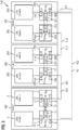
- the Fig. 1 shows a schematic representation of a first embodiment of a network arrangement.
- the network arrangement may for example be embedded in an Ethernet structure and comprise a plurality of network devices, which may also be referred to as network nodes, network users or as control components. Names such as network elements or network components are also common.
- a respective network device 1 which is labeled as "node 1", “node 2" and “node 3”, each comprises a control device 2, 202, 302, which may be configured, for example, as a microprocessor or CPU.
- the controller 2, 202, 302 can perform certain functions in the network. Functions as an actuator or sensor measurements are conceivable.
- the respective CPU 2, 202, 302 is assigned a switch device 4, 204, 304.
- the switch device 4, 204, 304 comprises a first port 7, 207, 307, which is communicatively connected to the respective CPU 2, 202, 302.
- each switch device 4, 204, 304 which is designed, for example, as an internal Ethernet switch, has two further ports 8, 9, 208, 209, 308, 309 for coupling to a communication network 6, which contains the data lines and thus communication paths for data packets exchanged between the network devices 1, 201, 301.
- the network arrangement 101 is operated by providing two VLAN networks VL1, VL2.
- the network devices 1, 201, 301 are arranged in a ring structure. That is, between the network device 1 and 201 is a communicative connection, for example, in the manner of a cable or another network link. Further, the network device 201 is communicatively coupled to the network device 301, and the network device 301 is coupled to the network device 1. This allows a ring structure for the VLANs VL1, VL2.
- VLAN ring VL1 is realized by potential data paths between the port 9 of the first switch device 4, the ports 208, 209 of the second switch device 204, the ports 308, 309 of the third switch device 304 and (but deactivated) the Port 8 of the first switch device 4.
- the network device 1 is a sending network device, thus supplying data to the other existing network nodes 201, 301.
- the second VLAN VL2 is in the manner of a ring through a communication path between the port 8 of the first switch device 4, the port 309 of third switch device 304, the port 308 of the third switch device 304 and the port 209 of the second switch device 204 and between the port 208 of the second switch device 204 and the (switched off for the VLAN VL2) port 9 of the first switch Device 4.
- the sending network device 1 that is, when the CPU 2 transfers data via the port 7 to the switch device 4, the data is transmitted on the one hand via the VLAN VL1 and on the other hand via the VLAN VL2.
- the first port 8 is activated for the VLAN VL2, whereas the other port 9 for the VLAN VL2 is deactivated.
- port 9 is enabled for VLAN VL1 and the other port 8 is disabled for VLAN VL1.
- the respective disabled port interrupts an unwanted ring closure in the VLAN.
- all ports are activated in a VLAN, except the non-sending port of the source node, which is in the Fig. 1 the network device 1 is.
- Broadcast or multicast destination addresses may be used for transmission so that in the ring network all other nodes or network devices 201, 301 receive the data. Also conceivable are unicast addresses to reach individual control devices.
- FIG. 2 shows essentially the same elements as in the Fig. 1 and shows two provided VLAN rings VL1 and VL2.
- the network devices 1, 201, 301 are configured with their switch devices 4, 204, 304 such that adjacent ports of different network devices 1, 201, 301 also forward data packets in a respective VLAN that could cause the ring to close.
- the port 8 not used for transmission is deactivated for the VLAN VL1 from the transmitting network device 1 or the node 1.
- both the port 8 of the transmitting network device 1 and the port 309 of the network device 301 receiving from the other VLAN VL2 are deactivated.
- port 9 and 208 for VLAN VL2 are disabled or disabled.
- the Fig. 3 shows a further embodiment of a network arrangement 110.
- the network devices 100, 200, 300 used are redundant, each with two CPUs 2, 3, 202, 203, 302, 303 and associated switch devices 4, 5, 204, 205, 304, 305 fitted.
- the switch devices of a network node are each communicatively coupled with each other.
- the switch device 4 is coupled to the switch device 5 internally via ports 11, 12.
- the switch device 204, 205 of the second node 200 are also internally coupled to each other via ports 211, 212.
- the switch devices 304, 305 of the third node 300 are coupled together via the ports 311, 312.
- the data of the redundant CPUs which are referred to as "channel a" and “channel b", are linked together via a coding.
- data may be generated by the CPU 2 that corresponds to a bit inversion of the data from CPU 3.
- the respective data from channels A and B can then be compared, and errors in data transmission can be inferred, or failures of network devices can be determined.
- the Fig. 4 and 5 show a fourth embodiment of a network arrangement 101.
- the network arrangement 111 may be part of a motor vehicle, are configured in the control components and various actuators, so adjusting elements as network devices.
- two ring structures are formed, which are coupled to one another via central Ethernet switches 501, 502.
- two control components or network devices 100, 200 are coupled to one another with the two Ethernet switches 501, 502 in a ring.
- Another second ring is formed by network devices 400, labeled "Actuator 1" through “Actuator 6".
- the actuator devices 400 each have an Ethernet switch 4 and are substantially the same as those in FIG Fig. 1 illustrated network device 1 constructed. No CPUs are shown in the actuator devices 400.
- the network arrangement 111 is based on an Ethernet protocol. This means that bidirectional or duplex connections are possible. This means that data communication can take place in two directions.
- a first virtual LAN VL1 for sending data from the control component 100 to the actuator component 400, which is labeled "actuator 3".
- the respective communication direction is indicated by the arrows between the network components 100, 200, 400, 500 indicated.
- the data packets DG correspond to those which run via the left branch, that is to say from the control component 100 via the switch device 501 and the actuator devices 400, which are designated "Actuator 1" and "Actuator 2".
- the data packets DGA are returning data packets.
- a right branch with data packets DB or DBA runs from the control component 100 to the control component 200 via the switch device 502 and the network devices 400 designated “Actuator 4" to "Actuator 6".
- FIG. 5 the operating situation of the network with the second VLAN VL2 is shown.
- the network paths are shaded underlined indicated.
- the first Ethernet switch device 501 or its ports 507, 508, 509 is deactivated. That is, there can be no network overload caused by circulating data packets.
- the in the FIGS. 4 to 7 Ported with individual reference numbers are combinations of transmit and receive ports. Based on the arrows indicating a data direction, and the symbols "s" and "r” results respectively, which port is addressed or disabled. For example, in FIG. 4 the send port "s" of the port combination 509 of the switch device 508 for the VLAN VL1 is deactivated.
- VL1 As stated in the Fig. 4 is indicated, and VL2, as in the Fig. 5 is indicated, are operated simultaneously, so that data simultaneously from the control component 1, 100 to be controlled actuator component actuator 3, 400. Even if data packets which are transmitted via a first VLAN VL1 are disturbed, the Actuator component 3, 400 nevertheless reliable data on the second VLAN VL2.
- FIG. 6 and 7 show a network arrangement 112, which essentially the same components as the network arrangement 111 of the Fig. 4 and 5 having.
- a VLAN VL1 is likewise provided (cf. Fig. 6 ) and a VLAN VL2 (cf. Fig. 7 ).
- the VLAN VL1 is indicated by dots and the VLAN VL2 is hatched diagonally.
- the Ethernet switch 502 or its ports 507, 508, 509 is deactivated. There is no forwarding of data packets that correspond to the VL1.
- the ports 207 of the adjacent control component 2, 200 are deactivated and the ports 407 of the actuator component 6, 400 likewise adjacent to the second ring. In this respect, the delimitation or termination of the VLAN ring VL1 is additionally improved. Even with errors in forwarding tables, for example in the Ethernet switch 502, the ports 407 and 207 of the actuator component 6, 400 and the control component 2, 200 stop the corresponding data packets.
- the Ethernet switch 501 or its ports 507, 508, 509 are blocked for the VLAN VL2.
- the adjacent ports 207, 407 of the control component 1, 100 of the upper ring structure and the actuator device 400 of the lower ring structure are deactivated. In this respect, even in the event of errors in forwarding tables of the Ethernet switch 501, it can be reliably prevented that data packets of the VLAN VL2 run in a circle and thus burden the network infrastructure unnecessarily.
- VLAN cross-connect can be made between source and destination nodes (VLAN-XC) or methods such as provider backbound bridging - traffic engineering (PBB-TE) can be used.
- PBB-TE provider backbound bridging - traffic engineering
- PRP can be used for the ring-shaped VLANs used, since several VLANs are provided simultaneously.
- VL1, VL2 are indicated in the examples, it is also possible to provide further VLANs by extending the port deactivation. Implementing more than two VLANs will further improve communication security.
Landscapes
- Engineering & Computer Science (AREA)
- Computer Networks & Wireless Communication (AREA)
- Signal Processing (AREA)
- Computer Security & Cryptography (AREA)
- Small-Scale Networks (AREA)
Claims (15)
- Procédé de fonctionnement d'un système de réseau (101) comportant plusieurs dispositifs de réseau (1, 201, 301) couplés les uns aux autres pour donner une structure annulaire, un dispositif de réseau respectif (1) comportant un dispositif de commande (2) et un dispositif de commutation (4) avec deux ports (8, 9) pour couplage à un chemin de communication, incluant :la mise à disposition simultanée de deux VLAN (VL1, VL2) dans la structure annulaire ;l'envoi d'un paquet de données du dispositif de commande (2) d'un dispositif de réseau (1) via un port (9) du dispositif de commutation (4) à l'un des deux VLAN (VL1), le procédé étant caractérisé en ce qu'il comprend les étapes suivantes :le paquet de données est envoyé simultanément aux deux VLAN (VL1, VL2) ; ;désactivation de l'autre port (8) du dispositif de commutation (4) du dispositif de réseau (1) pour l'un des VLAN (VL1) ; etdésactivation, pour l'un des VLAN (VL1), du port (309) d'un dispositif de commutation (304) d'un dispositif de réseau (301) recevant le paquet de données via l'un des VLAN (VL1), et qui est couplé à l'autre port (8) du dispositif de commutation (4) du dispositif de réseau (1) via l'autre des deux VLAN (VL2).
- Procédé selon la revendication 1, incluant en outre :l'envoi du paquet de données du dispositif de commande (2) du dispositif de réseau (1) via l'autre port (8) du dispositif de commutation (4) à l'autre des deux VLAN (VL2) ;
etla désactivation de l'un des ports (9) du dispositif de commutation (4) du dispositif de réseau (1) pour l'autre VLAN (VL2). - Procédé selon la revendication 1 ou 2, caractérisé en ce que le paquet de données est envoyé au moyen d'une adresse multicast.
- Procédé selon la revendication 1 ou 2, caractérisé en ce que le paquet de données est envoyé au moyen d'une adresse broadcast.
- Procédé selon l'une des revendications 1 à 4, incluant en outre la comparaison des paquets de données reçus via le premier VLAN (VL1) avec les paquets de données reçus via le deuxième VLAN (VL2).
- Procédé selon l'une des revendications 1 à 5, caractérisé en ce que les dispositifs de réseau (1, 201, 301) sont configurés pour fonctionner selon un protocole Ethernet.
- Procédé selon l'une des revendications 1 à 6, caractérisé en ce que, pour un VLAN respectif (VL1), tous les ports (9, 208, 209, 308, 309) des dispositifs de commutation (2, 202, 302) sont activés à l'exception du port (8) d'un dispositif de commutation (4) d'un dispositif de réseau (1) par lequel le paquet de données n'est pas émis.
- Produit de programme informatique qui fait exécuter un procédé selon l'une des revendications 1 à 7 sur un dispositif (1, 201, 301) commandé par programme.
- Support de données avec un programme informatique stocké comportant des commandes qui font exécuter un procédé selon l'une des revendications 1 à 7 sur un dispositif (1, 201, 301) commandé par programme.
- Système de réseau (101) comportant des dispositifs de réseau (1, 201, 301) couplés les uns aux autres pour donner une structure annulaire,
un dispositif de réseau respectif (1) comprenant un dispositif de commande et un dispositif de commutation (4) avec deux ports (8, 9) pour couplage à un chemin de communication ;
les dispositifs de réseau (1, 201, 301) étant configurés pour fournir en même temps deux VLAN (VL1, VL2) dans la structure annulaire ; et
le système de réseau étant caractérisé en ce que :les dispositifs de réseau (1, 201, 301) sont configurés de telle sorte que, lors de l'envoi d'un paquet de données du dispositif de commande (2) du dispositif de réseau (1) via un port (9) du dispositif de commutation (4) à l'un des deux VLAN (VL1), l'autre port (8) du dispositif de commutation (4) est désactivé pour l'un des VLAN (VL1), le paquet de données étant envoyé simultanément aux deux VLAN (VL1, VL2) ; etpour l'un des VLAN (VL1), le port (309) d'un dispositif de commutation (304) d'un dispositif de réseau (301) recevant le paquet de données via l'un des VLAN (VL1), et qui est couplé à l'autre port (8) du dispositif de commutation (4) du dispositif de réseau (1) via l'autre des deux VLAN (VL2), est désactivé. - Système de réseau (101) selon la revendication 10, caractérisé en ce que les dispositifs de réseau (1, 201, 202) sont configurés pour exécuter un procédé selon l'une des revendications 1 à 10.
- Système de réseau (101) selon la revendication 10 ou 11, caractérisé en ce qu'au moins un dispositif de réseau (100) comprend un premier et un deuxième dispositif de commutation (4, 5), le premier dispositif de commutation (4) étant affecté au premier dispositif de commande (2) et le deuxième dispositif de commutation (5) étant affecté à un deuxième dispositif de commande (3), et les dispositifs de commutation (4, 5) comprenant respectivement deux ports (7 à 12) et les dispositifs de commutation (4, 5) étant couplés entre eux communicativement.
- Système de réseau (111) selon l'une des revendications 10 à 12, caractérisé en ce que les dispositifs de réseau (100, 200, 400) forment une première et une deuxième structure annulaire, les structures annulaires étant couplées au moyen d'un ou de plusieurs dispositifs de commutation et de couplage (500).
- Système de réseau (111) selon la revendication 13, caractérisé en ce que les dispositifs de commutation et de couplage (500) sont configurés de telle sorte que des ports (507, 508, 509) du dispositif de commutation et de couplage (500) sont activés exclusivement pour l'un des VLAN (VL1, VL2).
- Système de réseau (1, 111) selon l'une des revendications 10 à 14, caractérisé en ce que le système de réseau (1, 111) est une partie d'un véhicule.
Applications Claiming Priority (2)
| Application Number | Priority Date | Filing Date | Title |
|---|---|---|---|
| DE102011082965A DE102011082965A1 (de) | 2011-09-19 | 2011-09-19 | Verfahren zum Betreiben einer Netzwerkanordnung und Netzwerkanordnung |
| PCT/EP2012/067121 WO2013041355A1 (fr) | 2011-09-19 | 2012-09-03 | Procédé de fonctionnement d'un ensemble de réseaux et ensemble de réseaux |
Publications (2)
| Publication Number | Publication Date |
|---|---|
| EP2721784A1 EP2721784A1 (fr) | 2014-04-23 |
| EP2721784B1 true EP2721784B1 (fr) | 2018-01-17 |
Family
ID=46851439
Family Applications (1)
| Application Number | Title | Priority Date | Filing Date |
|---|---|---|---|
| EP12759068.5A Active EP2721784B1 (fr) | 2011-09-19 | 2012-09-03 | Procédé de fonctionnement d' un équipement de réseau et équipement de réseau |
Country Status (7)
| Country | Link |
|---|---|
| US (1) | US9426094B2 (fr) |
| EP (1) | EP2721784B1 (fr) |
| JP (1) | JP5847314B2 (fr) |
| KR (1) | KR101741651B1 (fr) |
| CN (1) | CN103828306B (fr) |
| DE (1) | DE102011082965A1 (fr) |
| WO (1) | WO2013041355A1 (fr) |
Families Citing this family (19)
| Publication number | Priority date | Publication date | Assignee | Title |
|---|---|---|---|---|
| CN104702475A (zh) * | 2013-12-05 | 2015-06-10 | 上海博泰悦臻电子设备制造有限公司 | 车载信息系统及其组网方法 |
| US9647961B2 (en) * | 2014-02-14 | 2017-05-09 | Bedrock Automation Platforms Inc. | Communication network hopping architecture |
| DE102014109060B3 (de) | 2014-06-27 | 2015-09-24 | Beckhoff Automation Gmbh | Netzwerk, Kopf-Teilnehmer und Datenübertragungsverfahren |
| DE102014226994A1 (de) * | 2014-12-29 | 2016-06-30 | Robert Bosch Gmbh | Kommunikationssystem zum Betreiben eines Datennetzwerks |
| AT517779B1 (de) * | 2015-10-01 | 2021-10-15 | B & R Ind Automation Gmbh | Verfahren zum Querverkehr zwischen zwei Slaves eines ringförmigen Datennetzwerks |
| EP3211838B1 (fr) | 2016-02-29 | 2018-08-29 | Siemens Aktiengesellschaft | Systeme de communication industriel pouvant fonctionner de maniere redondante, son procede de fonctionnement et station emettrice/receptrice radio |
| EP3211962B1 (fr) | 2016-02-29 | 2018-09-12 | Siemens Aktiengesellschaft | Systeme de radiocommunication pour un systeme d'automatisation industriel, son procede de fonctionnement et station emettrice/receptrice radio |
| KR20180007342A (ko) * | 2016-07-12 | 2018-01-22 | 한국전기연구원 | 이중화 네트워크를 위한 통신 장치 및 그 데이터 처리 방법 |
| US10516625B2 (en) * | 2016-10-24 | 2019-12-24 | Hewlett Packard Enterprise Development Lp | Network entities on ring networks |
| US10404066B2 (en) * | 2016-11-16 | 2019-09-03 | En Technologies Inc. | Congestion management system and power-system management system for relieving overload of transmission line |
| JP6922375B2 (ja) * | 2017-04-20 | 2021-08-18 | 住友電気工業株式会社 | 車載通信システム、車載装置、通信制御方法および通信制御プログラム |
| EP3422641A1 (fr) | 2017-06-30 | 2019-01-02 | Siemens Aktiengesellschaft | Procédé de transmission de nouvelles dans un réseau de communication industriel à fonctionnement redondant et appareil destiné à son exécution |
| EP3575899B1 (fr) * | 2018-06-01 | 2021-03-17 | Selectron Systems AG | Système d'automatisation, procédé de fonctionnement pour système d'automatisation et produit de programme informatique |
| JP7211051B2 (ja) * | 2018-12-05 | 2023-01-24 | 株式会社デンソー | ネットワークスイッチおよび回線監視装置 |
| EP3690576B1 (fr) * | 2019-01-30 | 2024-04-24 | Schneider Electric Industries SAS | Dispositif de commande et procédé de commande d'une connexion redondante dans un réseau plat |
| EP3694156A1 (fr) * | 2019-02-07 | 2020-08-12 | Siemens Aktiengesellschaft | Procédé de transmission de données protégé contres les défaillances, noeuds de réseau, programme informatique et support lisible par ordinateur |
| JP7252097B2 (ja) * | 2019-08-30 | 2023-04-04 | トヨタ自動車株式会社 | 車載ネットワークシステム |
| FR3104345B1 (fr) * | 2019-12-09 | 2021-12-03 | Safran Aircraft Engines | Architecture mutualisée pour le pilotage d’actionneurs électromécaniques |
| LU501035B1 (de) * | 2021-12-17 | 2023-06-20 | Phoenix Contact Gmbh & Co | Verfahren und System zum Absichern des Austausches von Daten in einem Netzwerksystem für industrielle Steuerungen |
Family Cites Families (12)
| Publication number | Priority date | Publication date | Assignee | Title |
|---|---|---|---|---|
| ATE418198T1 (de) * | 2001-09-04 | 2009-01-15 | Rumi Sheryar Gonda | Verfahren zum unterstützen von sdh/sonet-aps auf ethernet |
| JP3904987B2 (ja) | 2002-06-26 | 2007-04-11 | 株式会社東芝 | データ伝送方法 |
| US8085676B2 (en) * | 2006-06-29 | 2011-12-27 | Nortel Networks Limited | Method and system for looping back traffic in QIQ ethernet rings and 1:1 protected PBT trunks |
| DE112007003486A5 (de) * | 2007-03-02 | 2010-02-04 | Siemens Aktiengesellschaft | Zielportsuche in Netzwerken aus gekoppelten Teilnetzen |
| CN100534048C (zh) * | 2007-04-27 | 2009-08-26 | 中控科技集团有限公司 | 分布式以太网系统及基于该系统的故障检测方法 |
| US8200850B2 (en) * | 2007-11-11 | 2012-06-12 | Weed Instrument, Inc. | Method, apparatus and computer program product for ring network communication |
| CN101188564B (zh) * | 2007-11-21 | 2010-06-02 | 中兴通讯股份有限公司 | 一种多生成树协议的实现方法 |
| JP2009212668A (ja) | 2008-03-03 | 2009-09-17 | Kddi Corp | 光伝送システム |
| US20100020809A1 (en) | 2008-07-25 | 2010-01-28 | Micrel, Inc. | True Ring Networks Using Tag VLAN Filtering |
| JP2010153944A (ja) | 2008-12-23 | 2010-07-08 | Fujitsu Ltd | 通信システム、受信装置、送信装置、および通信方法 |
| JP2009159636A (ja) | 2009-04-13 | 2009-07-16 | Toshiba Corp | データ伝送方法 |
| WO2011027361A2 (fr) * | 2009-09-07 | 2011-03-10 | Tejas Networks Limited | Procédé et système de commutation de protection d'anneau |
-
2011
- 2011-09-19 DE DE102011082965A patent/DE102011082965A1/de not_active Withdrawn
-
2012
- 2012-09-03 KR KR1020147010489A patent/KR101741651B1/ko not_active Expired - Fee Related
- 2012-09-03 EP EP12759068.5A patent/EP2721784B1/fr active Active
- 2012-09-03 WO PCT/EP2012/067121 patent/WO2013041355A1/fr not_active Ceased
- 2012-09-03 US US14/345,105 patent/US9426094B2/en active Active
- 2012-09-03 JP JP2014531161A patent/JP5847314B2/ja active Active
- 2012-09-03 CN CN201280045517.1A patent/CN103828306B/zh active Active
Also Published As
| Publication number | Publication date |
|---|---|
| CN103828306B (zh) | 2017-06-27 |
| US9426094B2 (en) | 2016-08-23 |
| JP2014526848A (ja) | 2014-10-06 |
| JP5847314B2 (ja) | 2016-01-20 |
| US20140341224A1 (en) | 2014-11-20 |
| WO2013041355A1 (fr) | 2013-03-28 |
| CN103828306A (zh) | 2014-05-28 |
| KR101741651B1 (ko) | 2017-06-15 |
| KR20140065453A (ko) | 2014-05-29 |
| EP2721784A1 (fr) | 2014-04-23 |
| DE102011082965A1 (de) | 2013-01-24 |
Similar Documents
| Publication | Publication Date | Title |
|---|---|---|
| EP2721784B1 (fr) | Procédé de fonctionnement d' un équipement de réseau et équipement de réseau | |
| EP2343857B1 (fr) | Noeud de réseau pour un réseau de communication | |
| DE102012209108B4 (de) | Netzwerkeinrichtung, Netzwerkanordnung und Verfahren zum Betreiben einer Netzwerkanordnung | |
| EP2838220B1 (fr) | Procédé de transmission redondante de messages dans un réseau de communication industriel et appareil de communication | |
| EP2693700B1 (fr) | Procédé de transmission de messages dans un réseau de communication industriel pouvant fonctionner de manière redondante et appareil de communication pour un réseau de communication industriel pouvant fonctionner de manière redondante | |
| EP2409458B1 (fr) | Exploitation en parallèle de protocoles rstp (rapid spanning tree protocol) et mrp (media redundancy protocol) et segmentation/couplage | |
| EP2783487B1 (fr) | Procédé d'exploitation d'un réseau de communication et système de réseau | |
| DE102007015539B4 (de) | Verfahren zum Rekonfigurieren eines Kommunikationsnetzwerks | |
| EP3228036B1 (fr) | Procédé et dispositif de commande pour la transmission de données relatives à la sécurité dans un véhicule automobile au moyen d'une norme éthernet | |
| WO2013186154A1 (fr) | Réseau en anneau pour véhicule | |
| WO2006108881A1 (fr) | Reseau de communication tolerant aux pannes et aux decouplages, dispositif d'inversion de chemin de donnees et procede correspondant | |
| WO2006108527A9 (fr) | Abonne, unite maitre, systeme de communication et procede pour les faire fonctionner | |
| EP2880823B1 (fr) | Réseau de communication et procédé d'utilisation d'un réseau de communication | |
| EP2652917B1 (fr) | Réseau intermédiaire de topologie annulaire et procédé de création d'une liaison de réseau entre deux domaines d'un réseau | |
| EP2704370B1 (fr) | Procédé de transmission de nouvelles dans un réseau de communication industriel pouvant fonctionner de manière redondante et appareil de communication pour un réseau de communication industriel pouvant fonctionner de manière redondante | |
| WO2003073703A2 (fr) | Reseau local, en particulier reseau ethernet presentant des proprietes de redondance et appareil de couplage destine a un reseau de ce type | |
| EP2182680B1 (fr) | Procédé destiné au fonctionnement d'un réseau de communication et composants de communication | |
| EP2817923B1 (fr) | Réseau de calculateurs avec un bus de liaison de forme annulaire | |
| WO2013041352A1 (fr) | Dispositif de réseau et ensemble de réseaux | |
| WO2008015035A1 (fr) | Procédé pour la transmission de données par paquets dans un reseau de communication | |
| EP2721771A2 (fr) | Procédé d'interconnexion redondante et à faibles perturbations de réseaux de communication à l'aide du protocole d'arbre couvrant rapide rstp (rapid spanning tree) | |
| DE102007021922A1 (de) | Paketvermitteltes Kommunikationsnetzwerk und Verfahren zum Rekonfigurieren des Kommunikationsnetzwerks | |
| EP2750340A1 (fr) | Procédé de transmission de nouvelles dans un réseau de communication industriel à fonctionnement redondant et appareil d'infrastructure de réseau |
Legal Events
| Date | Code | Title | Description |
|---|---|---|---|
| PUAI | Public reference made under article 153(3) epc to a published international application that has entered the european phase |
Free format text: ORIGINAL CODE: 0009012 |
|
| 17P | Request for examination filed |
Effective date: 20140114 |
|
| AK | Designated contracting states |
Kind code of ref document: A1 Designated state(s): AL AT BE BG CH CY CZ DE DK EE ES FI FR GB GR HR HU IE IS IT LI LT LU LV MC MK MT NL NO PL PT RO RS SE SI SK SM TR |
|
| DAX | Request for extension of the european patent (deleted) | ||
| 17Q | First examination report despatched |
Effective date: 20160819 |
|
| GRAP | Despatch of communication of intention to grant a patent |
Free format text: ORIGINAL CODE: EPIDOSNIGR1 |
|
| RAP1 | Party data changed (applicant data changed or rights of an application transferred) |
Owner name: SIEMENS AKTIENGESELLSCHAFT |
|
| RIC1 | Information provided on ipc code assigned before grant |
Ipc: H04L 12/46 20060101ALI20170803BHEP Ipc: H04L 12/437 20060101ALI20170803BHEP Ipc: H04L 12/935 20130101ALI20170803BHEP Ipc: H04L 12/42 20060101AFI20170803BHEP Ipc: H04L 12/24 20060101ALI20170803BHEP |
|
| INTG | Intention to grant announced |
Effective date: 20170818 |
|
| GRAS | Grant fee paid |
Free format text: ORIGINAL CODE: EPIDOSNIGR3 |
|
| GRAA | (expected) grant |
Free format text: ORIGINAL CODE: 0009210 |
|
| AK | Designated contracting states |
Kind code of ref document: B1 Designated state(s): AL AT BE BG CH CY CZ DE DK EE ES FI FR GB GR HR HU IE IS IT LI LT LU LV MC MK MT NL NO PL PT RO RS SE SI SK SM TR |
|
| REG | Reference to a national code |
Ref country code: GB Ref legal event code: FG4D Free format text: NOT ENGLISH |
|
| REG | Reference to a national code |
Ref country code: CH Ref legal event code: EP |
|
| REG | Reference to a national code |
Ref country code: IE Ref legal event code: FG4D Free format text: LANGUAGE OF EP DOCUMENT: GERMAN |
|
| REG | Reference to a national code |
Ref country code: AT Ref legal event code: REF Ref document number: 965098 Country of ref document: AT Kind code of ref document: T Effective date: 20180215 |
|
| REG | Reference to a national code |
Ref country code: DE Ref legal event code: R096 Ref document number: 502012012037 Country of ref document: DE |
|
| REG | Reference to a national code |
Ref country code: SE Ref legal event code: TRGR |
|
| REG | Reference to a national code |
Ref country code: NL Ref legal event code: MP Effective date: 20180117 |
|
| REG | Reference to a national code |
Ref country code: LT Ref legal event code: MG4D |
|
| PG25 | Lapsed in a contracting state [announced via postgrant information from national office to epo] |
Ref country code: NL Free format text: LAPSE BECAUSE OF FAILURE TO SUBMIT A TRANSLATION OF THE DESCRIPTION OR TO PAY THE FEE WITHIN THE PRESCRIBED TIME-LIMIT Effective date: 20180117 |
|
| PG25 | Lapsed in a contracting state [announced via postgrant information from national office to epo] |
Ref country code: FI Free format text: LAPSE BECAUSE OF FAILURE TO SUBMIT A TRANSLATION OF THE DESCRIPTION OR TO PAY THE FEE WITHIN THE PRESCRIBED TIME-LIMIT Effective date: 20180117 Ref country code: CY Free format text: LAPSE BECAUSE OF FAILURE TO SUBMIT A TRANSLATION OF THE DESCRIPTION OR TO PAY THE FEE WITHIN THE PRESCRIBED TIME-LIMIT Effective date: 20180117 Ref country code: ES Free format text: LAPSE BECAUSE OF FAILURE TO SUBMIT A TRANSLATION OF THE DESCRIPTION OR TO PAY THE FEE WITHIN THE PRESCRIBED TIME-LIMIT Effective date: 20180117 Ref country code: LT Free format text: LAPSE BECAUSE OF FAILURE TO SUBMIT A TRANSLATION OF THE DESCRIPTION OR TO PAY THE FEE WITHIN THE PRESCRIBED TIME-LIMIT Effective date: 20180117 Ref country code: HR Free format text: LAPSE BECAUSE OF FAILURE TO SUBMIT A TRANSLATION OF THE DESCRIPTION OR TO PAY THE FEE WITHIN THE PRESCRIBED TIME-LIMIT Effective date: 20180117 Ref country code: NO Free format text: LAPSE BECAUSE OF FAILURE TO SUBMIT A TRANSLATION OF THE DESCRIPTION OR TO PAY THE FEE WITHIN THE PRESCRIBED TIME-LIMIT Effective date: 20180417 |
|
| PG25 | Lapsed in a contracting state [announced via postgrant information from national office to epo] |
Ref country code: GR Free format text: LAPSE BECAUSE OF FAILURE TO SUBMIT A TRANSLATION OF THE DESCRIPTION OR TO PAY THE FEE WITHIN THE PRESCRIBED TIME-LIMIT Effective date: 20180418 Ref country code: BG Free format text: LAPSE BECAUSE OF FAILURE TO SUBMIT A TRANSLATION OF THE DESCRIPTION OR TO PAY THE FEE WITHIN THE PRESCRIBED TIME-LIMIT Effective date: 20180417 Ref country code: RS Free format text: LAPSE BECAUSE OF FAILURE TO SUBMIT A TRANSLATION OF THE DESCRIPTION OR TO PAY THE FEE WITHIN THE PRESCRIBED TIME-LIMIT Effective date: 20180117 Ref country code: PL Free format text: LAPSE BECAUSE OF FAILURE TO SUBMIT A TRANSLATION OF THE DESCRIPTION OR TO PAY THE FEE WITHIN THE PRESCRIBED TIME-LIMIT Effective date: 20180117 Ref country code: IS Free format text: LAPSE BECAUSE OF FAILURE TO SUBMIT A TRANSLATION OF THE DESCRIPTION OR TO PAY THE FEE WITHIN THE PRESCRIBED TIME-LIMIT Effective date: 20180517 Ref country code: LV Free format text: LAPSE BECAUSE OF FAILURE TO SUBMIT A TRANSLATION OF THE DESCRIPTION OR TO PAY THE FEE WITHIN THE PRESCRIBED TIME-LIMIT Effective date: 20180117 |
|
| REG | Reference to a national code |
Ref country code: FR Ref legal event code: PLFP Year of fee payment: 7 |
|
| PG25 | Lapsed in a contracting state [announced via postgrant information from national office to epo] |
Ref country code: MT Free format text: LAPSE BECAUSE OF FAILURE TO SUBMIT A TRANSLATION OF THE DESCRIPTION OR TO PAY THE FEE WITHIN THE PRESCRIBED TIME-LIMIT Effective date: 20180117 |
|
| REG | Reference to a national code |
Ref country code: DE Ref legal event code: R097 Ref document number: 502012012037 Country of ref document: DE |
|
| PG25 | Lapsed in a contracting state [announced via postgrant information from national office to epo] |
Ref country code: EE Free format text: LAPSE BECAUSE OF FAILURE TO SUBMIT A TRANSLATION OF THE DESCRIPTION OR TO PAY THE FEE WITHIN THE PRESCRIBED TIME-LIMIT Effective date: 20180117 Ref country code: AL Free format text: LAPSE BECAUSE OF FAILURE TO SUBMIT A TRANSLATION OF THE DESCRIPTION OR TO PAY THE FEE WITHIN THE PRESCRIBED TIME-LIMIT Effective date: 20180117 Ref country code: RO Free format text: LAPSE BECAUSE OF FAILURE TO SUBMIT A TRANSLATION OF THE DESCRIPTION OR TO PAY THE FEE WITHIN THE PRESCRIBED TIME-LIMIT Effective date: 20180117 Ref country code: IT Free format text: LAPSE BECAUSE OF FAILURE TO SUBMIT A TRANSLATION OF THE DESCRIPTION OR TO PAY THE FEE WITHIN THE PRESCRIBED TIME-LIMIT Effective date: 20180117 |
|
| PLBE | No opposition filed within time limit |
Free format text: ORIGINAL CODE: 0009261 |
|
| STAA | Information on the status of an ep patent application or granted ep patent |
Free format text: STATUS: NO OPPOSITION FILED WITHIN TIME LIMIT |
|
| PG25 | Lapsed in a contracting state [announced via postgrant information from national office to epo] |
Ref country code: DK Free format text: LAPSE BECAUSE OF FAILURE TO SUBMIT A TRANSLATION OF THE DESCRIPTION OR TO PAY THE FEE WITHIN THE PRESCRIBED TIME-LIMIT Effective date: 20180117 Ref country code: SM Free format text: LAPSE BECAUSE OF FAILURE TO SUBMIT A TRANSLATION OF THE DESCRIPTION OR TO PAY THE FEE WITHIN THE PRESCRIBED TIME-LIMIT Effective date: 20180117 Ref country code: SK Free format text: LAPSE BECAUSE OF FAILURE TO SUBMIT A TRANSLATION OF THE DESCRIPTION OR TO PAY THE FEE WITHIN THE PRESCRIBED TIME-LIMIT Effective date: 20180117 |
|
| 26N | No opposition filed |
Effective date: 20181018 |
|
| PG25 | Lapsed in a contracting state [announced via postgrant information from national office to epo] |
Ref country code: SI Free format text: LAPSE BECAUSE OF FAILURE TO SUBMIT A TRANSLATION OF THE DESCRIPTION OR TO PAY THE FEE WITHIN THE PRESCRIBED TIME-LIMIT Effective date: 20180117 |
|
| PG25 | Lapsed in a contracting state [announced via postgrant information from national office to epo] |
Ref country code: MC Free format text: LAPSE BECAUSE OF FAILURE TO SUBMIT A TRANSLATION OF THE DESCRIPTION OR TO PAY THE FEE WITHIN THE PRESCRIBED TIME-LIMIT Effective date: 20180117 |
|
| REG | Reference to a national code |
Ref country code: CH Ref legal event code: PL |
|
| REG | Reference to a national code |
Ref country code: BE Ref legal event code: MM Effective date: 20180930 |
|
| REG | Reference to a national code |
Ref country code: IE Ref legal event code: MM4A |
|
| PG25 | Lapsed in a contracting state [announced via postgrant information from national office to epo] |
Ref country code: LU Free format text: LAPSE BECAUSE OF NON-PAYMENT OF DUE FEES Effective date: 20180903 |
|
| PG25 | Lapsed in a contracting state [announced via postgrant information from national office to epo] |
Ref country code: IE Free format text: LAPSE BECAUSE OF NON-PAYMENT OF DUE FEES Effective date: 20180903 |
|
| PG25 | Lapsed in a contracting state [announced via postgrant information from national office to epo] |
Ref country code: CH Free format text: LAPSE BECAUSE OF NON-PAYMENT OF DUE FEES Effective date: 20180930 Ref country code: LI Free format text: LAPSE BECAUSE OF NON-PAYMENT OF DUE FEES Effective date: 20180930 Ref country code: BE Free format text: LAPSE BECAUSE OF NON-PAYMENT OF DUE FEES Effective date: 20180930 |
|
| REG | Reference to a national code |
Ref country code: AT Ref legal event code: MM01 Ref document number: 965098 Country of ref document: AT Kind code of ref document: T Effective date: 20180903 |
|
| PG25 | Lapsed in a contracting state [announced via postgrant information from national office to epo] |
Ref country code: AT Free format text: LAPSE BECAUSE OF NON-PAYMENT OF DUE FEES Effective date: 20180903 |
|
| PG25 | Lapsed in a contracting state [announced via postgrant information from national office to epo] |
Ref country code: TR Free format text: LAPSE BECAUSE OF FAILURE TO SUBMIT A TRANSLATION OF THE DESCRIPTION OR TO PAY THE FEE WITHIN THE PRESCRIBED TIME-LIMIT Effective date: 20180117 |
|
| PG25 | Lapsed in a contracting state [announced via postgrant information from national office to epo] |
Ref country code: PT Free format text: LAPSE BECAUSE OF FAILURE TO SUBMIT A TRANSLATION OF THE DESCRIPTION OR TO PAY THE FEE WITHIN THE PRESCRIBED TIME-LIMIT Effective date: 20180117 Ref country code: HU Free format text: LAPSE BECAUSE OF FAILURE TO SUBMIT A TRANSLATION OF THE DESCRIPTION OR TO PAY THE FEE WITHIN THE PRESCRIBED TIME-LIMIT; INVALID AB INITIO Effective date: 20120903 |
|
| PG25 | Lapsed in a contracting state [announced via postgrant information from national office to epo] |
Ref country code: MK Free format text: LAPSE BECAUSE OF NON-PAYMENT OF DUE FEES Effective date: 20180117 |
|
| P01 | Opt-out of the competence of the unified patent court (upc) registered |
Effective date: 20230510 |
|
| PGFP | Annual fee paid to national office [announced via postgrant information from national office to epo] |
Ref country code: FR Payment date: 20240916 Year of fee payment: 13 |
|
| PGFP | Annual fee paid to national office [announced via postgrant information from national office to epo] |
Ref country code: CZ Payment date: 20240826 Year of fee payment: 13 |
|
| PGFP | Annual fee paid to national office [announced via postgrant information from national office to epo] |
Ref country code: SE Payment date: 20240905 Year of fee payment: 13 |
|
| PGFP | Annual fee paid to national office [announced via postgrant information from national office to epo] |
Ref country code: DE Payment date: 20241118 Year of fee payment: 13 |
|
| PGFP | Annual fee paid to national office [announced via postgrant information from national office to epo] |
Ref country code: GB Payment date: 20241007 Year of fee payment: 13 |
|
| PG25 | Lapsed in a contracting state [announced via postgrant information from national office to epo] |
Ref country code: CZ Free format text: LAPSE BECAUSE OF NON-PAYMENT OF DUE FEES Effective date: 20250903 |