EP2344410B1 - Dispositif de fermeture pour conteneurs avec espace stérile - Google Patents
Dispositif de fermeture pour conteneurs avec espace stérile Download PDFInfo
- Publication number
- EP2344410B1 EP2344410B1 EP09740113.7A EP09740113A EP2344410B1 EP 2344410 B1 EP2344410 B1 EP 2344410B1 EP 09740113 A EP09740113 A EP 09740113A EP 2344410 B1 EP2344410 B1 EP 2344410B1
- Authority
- EP
- European Patent Office
- Prior art keywords
- movement
- containers
- closure
- sterile space
- movement device
- Prior art date
- Legal status (The legal status is an assumption and is not a legal conclusion. Google has not performed a legal analysis and makes no representation as to the accuracy of the status listed.)
- Not-in-force
Links
Images

Classifications
-
- B—PERFORMING OPERATIONS; TRANSPORTING
- B67—OPENING, CLOSING OR CLEANING BOTTLES, JARS OR SIMILAR CONTAINERS; LIQUID HANDLING
- B67B—APPLYING CLOSURE MEMBERS TO BOTTLES JARS, OR SIMILAR CONTAINERS; OPENING CLOSED CONTAINERS
- B67B3/00—Closing bottles, jars or similar containers by applying caps
- B67B3/20—Closing bottles, jars or similar containers by applying caps by applying and rotating preformed threaded caps
- B67B3/2013—Closing bottles, jars or similar containers by applying caps by applying and rotating preformed threaded caps by carousel-type capping machines
- B67B3/2033—Closing bottles, jars or similar containers by applying caps by applying and rotating preformed threaded caps by carousel-type capping machines comprising carousel co-rotating capping heads
-
- B—PERFORMING OPERATIONS; TRANSPORTING
- B67—OPENING, CLOSING OR CLEANING BOTTLES, JARS OR SIMILAR CONTAINERS; LIQUID HANDLING
- B67B—APPLYING CLOSURE MEMBERS TO BOTTLES JARS, OR SIMILAR CONTAINERS; OPENING CLOSED CONTAINERS
- B67B2201/00—Indexing codes relating to constructional features of closing machines
- B67B2201/08—Aseptic features
-
- B—PERFORMING OPERATIONS; TRANSPORTING
- B67—OPENING, CLOSING OR CLEANING BOTTLES, JARS OR SIMILAR CONTAINERS; LIQUID HANDLING
- B67C—CLEANING, FILLING WITH LIQUIDS OR SEMILIQUIDS, OR EMPTYING, OF BOTTLES, JARS, CANS, CASKS, BARRELS, OR SIMILAR CONTAINERS, NOT OTHERWISE PROVIDED FOR; FUNNELS
- B67C3/00—Bottling liquids or semiliquids; Filling jars or cans with liquids or semiliquids using bottling or like apparatus; Filling casks or barrels with liquids or semiliquids
- B67C3/02—Bottling liquids or semiliquids; Filling jars or cans with liquids or semiliquids using bottling or like apparatus
- B67C3/22—Details
- B67C2003/228—Aseptic features
Definitions
- the present invention relates to a device for closing containers.
- Such devices have been known for a long time from the prior art.
- a closure such as a screw cap or a bottle cap.
- the present invention is therefore based on the object to provide a device of containers, which is also able to handle relatively strong strokes of a Verschbooimplantations. This is inventively achieved by a device according to claim 1.
- Advantageous embodiments and further developments are the subject of the dependent claims.
- the sterile space is bounded by at least one first wall and has an annular channel into which this first wall protrudes, wherein the annular channel is movable relative to the first wall and can be filled with a liquid medium and wherein the first movement device is at least partially within the first Channel is arranged.
- the movement device can be a device which generates a specific movement, such as a lifting movement or a rotational movement. More preferably, however, it is a movement transmission device which transmits a movement generated in particular outside the sterile room to a moving element within the sterile room and in particular exceeds a sterile room boundary of the sterile room.
- the mentioned annular channel forms, together with the wall, a so-called water lock, which seals the non-sterile area with respect to the sterile area.
- this water lock or this annular channel is also used to carry out the movement device and, more precisely, that the annular channel is also used in order to seal the movement device tightly from the non-sterile area to reach the sterile area.
- the channel also serves the purpose of introducing said moving means from the non-sterile area to the sterile area.
- the device has a first drive device for driving the closure head, wherein this drive device is arranged outside the sterile room and coupled to the movement device.
- the drive device may be, for example, an electric motor, but it would also be possible for the drive device to be designed in the form of a guide curve which causes a lifting movement of the movement device and thus also of the closure head.
- the closure head is movable relative to the container in a second movement type different from the first, and a second movement device for generating this second movement is arranged outside the sterile room.
- a second movement device for generating this second movement is arranged outside the sterile room.
- the second Movement can again be a lifting movement, a pivoting movement, a rotational movement and the like.
- the first type of movement is a lifting movement and the second type of movement is a rotary movement, so that the closure head is displaceable both in the longitudinal direction of the container and rotatable to attach closures to the containers.
- the device has a further movement device, which transmits a movement of the drive element to the closure head.
- a further movement device which transmits a movement of the drive element to the closure head.
- the first movement device and the second movement device are separated from each other.
- it would also be possible to accomplish the rotational movement for example, by an electric motor and to lift and lower this electric motor in its entirety, so that, for example, only a rotatable and displaceable moving device is provided, which provides the containers with closures.
- at least one movement type is a rotary movement and in a further advantageous embodiment at least one movement type is a lifting movement, in particular in a longitudinal direction of the containers.
- the device also has a second drive device for driving the closure head, wherein the second drive device is arranged outside the sterile room.
- the first drive device may be a lift curve and the second drive device may be an electric motor that generates the rotational movement.
- a driving wheel is provided in the interior of the sterile room, the rotational movement of which is coupled to at least one drive device and a wheel driven by this driving wheel, wherein the driven wheel is displaceable relative to the driving wheel in the direction of the axis of rotation of the driven wheel.
- the driven and the driving wheels are each gears.
- the driving wheel is a long wheel, i. a wheel which is considerably longer in the direction of its axis of rotation than the driven wheel.
- the driven wheel could correspondingly also be such a long wheel.
- the device has a second movement device, which transmits a movement of the second drive device to the driving gear, wherein preferably also the second movement device extends through the annular channel.
- the drive devices is designed as an electric motor.
- the (first) movement device extends at least partially within a hollow body, wherein said hollow body is disposed within said channel.
- a hollow body is preferably a cylindrical body with a particularly preferred circular cross-section.
- This hollow body is preferably fixedly arranged on the said channel and completely surrounded by separation media.
- this separating medium can be, for example, water or sterile or sterilizing or disinfecting liquids.
- a cylindrical body projecting into the channel is arranged on the movement device and completely surrounds the movement device in the circumferential direction.
- this cylindrical body also completely surrounds the above-mentioned hollow body in the circumferential direction.
- this body is always in the liquid arranged, that is independent of any stroke position of the movement device. In this way, an advantageous sealing of the two elements, ie the movement device and the hollow body against each other can be achieved.
- the present invention is further directed to an apparatus for closing containers with closures, comprising a closure head which attaches the closures to the containers, said closure head being movable relative to the closures in a first mode of movement and disposed within a sterile room. Furthermore, the device has a first movement device for generating a movement of the closure head in the first movement, said first movement device is at least partially disposed outside of the sterile room.
- the sterile space is delimited by at least one first wall and the device has a container which can be filled with a liquid medium and the first movement device is arranged at least in sections within the container.
- the container is not necessarily a water lock for sealing a rotary movement, but a container is provided, which serves specifically for sealing the movement in said movement and in particular a lifting movement ,
- the movement device is preferably completely surrounded by the liquid medium, but does not touch this medium directly.
- a cylindrical body is also preferably provided here, within which the movement device extends, and furthermore, a sealing element or a further hollow body is preferably also provided on the movement device, which is permanently, i. regardless of a stroke position of the moving device always immersed in the liquid medium.
- the present invention is further directed to a method for closing containers with closures, wherein for this purpose the containers are passed through a sterile room and closing by means of a closure head and the closure head is moved to close the containers in a first movement and movement in This first movement is generated by a first movement device, which is at least partially outside the sterile room and preferably at least partially disposed within the sterile room. In particular, this movement device is moved relative to the sterile room.
- the sterile space is delimited by at least one first wall and has an annular channel into which this first wall protrudes, wherein the annular channel is moved relative to the first wall and filled with a liquid medium and wherein the first movement device at least partially within the first Channel is moved.
- the containers are preferably moved inside the sterile room and particularly preferably along a substantially circular path.
- Fig. 1 shows a schematic representation of a device 1 according to the invention for closing containers (not shown).
- This device 1 in this case has a central shaft 3, on which a carrier 5 is arranged.
- a carrier 5 On this carrier in turn is a variety of Closure heads 2 are arranged, which close (not shown) containers with closures.
- these individual closure heads 2 are rotated together with the carrier 5 with respect to a rotation axis X and during this rotation, a closure of the containers is made.
- the individual closure heads 2 are constantly arranged within a sterile room 8.
- the reference numeral 16 refers to a drive means which moves the shutter heads along the arrow P1, i. here up and down.
- This driving device 16 may here be designed as a lift curve, which in particular in the region N, i. outside the sterile room 8 is arranged.
- a so-called water lock is used here.
- This water lock has an annular channel 14 which is filled with a liquid 18.
- the reference numeral 12 refers to a fixed wall, which also delimits the sterile room 8. In this case, a portion 12a permanently protrudes into the liquid 18, so that in this way a seal between stationary and rotating parts of the device is achieved.
- the drive device 16 transmits the lifting movement to a movement device 4, and the movement device 4 is in turn coupled to the closure head 2 arranged in the interior. It extends as if from Fig. 1 this movement device can be seen through the channel 14 and is thus arranged in sections within the sterile room 8 and partly outside thereof.
- the reference numeral 14a refers to an inner wall of the channel 14, the reference numeral 14b to a Bottom of the channel 14, which decreases obliquely here recognizably radially outwardly, and the reference numeral 14c on a (radial) outer wall of the channel.
- the outer wall may not only at its upper end, as in Fig. 1 shown, cylindrically leak, but also have a radially inwardly directed fold.
- This fold (not shown) can also be present twice or be executed as a curve, ie the end of the wall is directed substantially to the liquid level of the liquid 18. This advantageously prevents the fluid 18 from spilling out of the channel 14 into the sterile area 8 when the speed of rotation of the device 1 is reduced.
- Fig. 1 it can be seen that the movement device 4 is arranged radially inside the wall section 12a.
- the same channel 14, which is used to seal the sterile room 8 is also used to seal the movement of the movement device 4, which projects from the outside into the sterile room 8.
- the reference numeral 28 refers to a further drive device, which has an electric motor which ensures a rotational movement of the closure head 2.
- this electric motor is arranged radially inside the annular channel 14 here.
- a sealing ring or the like could, for example, be used in the region of the movement device 22, for example an output shaft of the electric motor, in order to prevent the entry of soiling in the sterile room. It would also be possible to provide a gas extraction in this area.
- the movement device 22 drives a drive wheel 32 which is designed here as a long wheel, which extends significantly further in the direction of the stroke movement P1 than a wheel 34 driven by it. This means that the driven wheel 34 is independent of a stroke position of the movement device 4 always engages in the driven gear 32.
- the reference numeral 42 refers to a cylindrical body, which is here in the annular channel 14 and preferably fixedly disposed therein. Within this cylindrical body, the movement device 4 is guided, whereby also here a seal between the sterile room 8 and the area outside the sterile room 8 is achieved. On the moving means 4, another cylindrical body 44 is arranged, wherein a peripheral wall 44a of the cylindrical body 44 is always, i. protrudes into the liquid 18 regardless of a position of the moving element.
- the sterile room 8 would communicate with the area N outside the sterile room 8 via the hollow body 42. Due to the interaction of the cylindrical body 44, more precisely, the peripheral wall 44a arranged thereon, a seal via the liquid 18 is likewise achieved.
- the movement to be sealed in the present case is not a transverse movement but a lifting movement that can take place within this water container.
- a plurality of containers may be arranged, in each of which liquid is located and in these containers could continue each cylindrical body 44 of in Fig. 1 be shown kind arranged. It would also be possible to connect the containers mentioned together in the manner of communicating tubes.
- Fig. 1 The advantage of in Fig. 1 However, the embodiment shown is that only one channel to be refilled is provided and thus can be used with relatively few state sensors or the like, which monitor a state level of the liquid 18.
- Fig. 2 shows a further embodiment of the device according to the invention.
- This device corresponds to the arrangement of the annular channel 14 of FIG Fig. 1 shown embodiment.
- An essential difference to the in Fig. 1 embodiment shown, however, is that only one movement device. 4 is provided, which transmits both a lifting movement and a rotational movement.
- a drive device such as a motor is provided outside of the sterile room 8, but which is also moved, for example, by a lifting movement along the double arrow P1.
- a corresponding electric motor is held stationary and in each case a telescopic movement device is provided, which in turn transmits the lifting movement to the closure head 2.
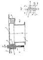
- Fig. 3 schematically illustrates the idea underlying the present invention.
- a container 54 is provided with a bottom 54b.
- a hollow cylinder 52 is provided, wherein this hollow cylinder 52 is liquid-tightly connected to the bottom 54b and is completely surrounded by liquid 18.
- a second cylindrical body 56 is arranged, which moves with the movement device 4.
- the movement in FIG. 3 is a lifting movement, but it would also be possible to seal a rotary movement. In this way, the sterile room 8 is always sealed from the outside area N independently of a position of the movement device 4.
Landscapes
- Engineering & Computer Science (AREA)
- Mechanical Engineering (AREA)
- Sealing Of Jars (AREA)
- Apparatus Associated With Microorganisms And Enzymes (AREA)
- Basic Packing Technique (AREA)
- Filling Of Jars Or Cans And Processes For Cleaning And Sealing Jars (AREA)
- Closures For Containers (AREA)
- Closing Of Containers (AREA)
Claims (15)
- Système de fermeture de récipients par des bouchons au moyen d'une tête de fermeture (2) appliquant les bouchons sur les récipients, ladite tête de fermeture (2) étant déplaçable dans un premier mode de déplacement par rapport aux bouchons et étant disposée à l'intérieur d'un espace stérile (8) avec un premier dispositif de déplacement (4) pour générer un mouvement du bouchon dans le premier mode de déplacement, ledit premier dispositif de déplacement (4) étant au moins partiellement disposé à l'extérieur de l'espace stérile (8), caractérisé en ce que l'espace stérile (8) est délimité par au moins une première paroi (12) et en ce que le système comporte un canal annulaire (14) où pénètre ladite première paroi (12), le canal annulaire (14) étant déplaçable par rapport à la première paroi (12) et pouvant être rempli d'un fluide liquide, et le premier dispositif de déplacement (4) étant au moins partiellement disposé à l'intérieur du canal (14).
- Système selon la revendication 1, caractérisé en ce que ledit système comporte un premier dispositif d'entraînement (16) pour l'entraînement de la tête de fermeture (2), ledit dispositif d'entraînement (16) étant disposé à l'extérieur de l'espace stérile (8) et étant relié au dispositif de déplacement (4).
- Système selon au moins une des revendications précédentes, caractérisé en ce que la tête de fermeture (2) est déplaçable par rapport au récipient dans un deuxième mode de déplacement différent du premier mode de déplacement.
- Système selon la revendication 3, caractérisé en ce que ledit système comporte un deuxième dispositif de déplacement (22) qui transmet un mouvement de l'élément d'entraînement à la tête de fermeture.
- Système selon la revendication 4, caractérisé en ce que le premier dispositif de déplacement (4) et le deuxième dispositif de déplacement (22) sont séparés l'un de l'autre.
- Système selon au moins une des revendications précédentes, caractérisé en ce qu'au moins un mode de déplacement est un mouvement de rotation.
- Système selon au moins une des revendications précédentes, caractérisé en ce qu'au moins un mode de déplacement est un mouvement de levage, en particulier dans la direction longitudinale des récipients.
- Système selon au moins une des revendications 3 à 5, caractérisé en ce que les modes de déplacement sont accouplés à l'intérieur de l'espace stérile.
- Système selon au moins une des revendications précédentes, caractérisé en ce que ledit système comporte un deuxième dispositif d'entraînement (28) pour l'entraînement de la tête de fermeture (2), ledit deuxième dispositif d'entraînement (28) étant disposé à l'extérieur de l'espace stérile (8).
- Système selon au moins une des revendications précédentes, caractérisé en ce qu'une roue d'entraînement (32) est prévue à l'intérieur de l'espace stérile, dont la rotation est reliée à au moins un dispositif d'entraînement (28) ainsi qu'à une roue entraînée (34) par ladite roue d'entraînement (32), la roue entraînée étant déplaçable par rapport à la roue d'entraînement (32) dans la direction de l'axe de rotation de la roue entraînée.
- Système selon la revendication 10, caractérisé en ce que ledit système comporte un deuxième dispositif de déplacement (22) qui transmet un mouvement du deuxième dispositif d'entraînement (28) à la roue dentée d'entraînement (32), le deuxième dispositif de déplacement (22) s'étendant de préférence également au travers du canal annulaire (14).
- Système selon au moins une des revendications précédentes, caractérisé en ce que le dispositif de déplacement (4) s'étend au moins partiellement à l'intérieur d'un corps creux (42), ledit corps creux (42) étant disposé à l'intérieur du canal (14).
- Système selon la revendication 12, caractérisé en ce qu'un corps cylindrique (44) pénétrant dans le canal (14) est monté sur le dispositif de déplacement (4), lequel entoure complètement le dispositif de déplacement (4) dans la direction périphérique.
- Système de fermeture de récipients par des bouchons au moyen d'une tête de fermeture appliquant les bouchons sur les récipients, ladite tête de fermeture étant déplaçable dans un premier mode de déplacement par rapport aux bouchons et étant disposée à l'intérieur d'un espace stérile (8) avec un premier dispositif de déplacement (4) pour générer un mouvement du bouchon dans le premier mode de déplacement, ledit premier dispositif de déplacement (4) étant au moins partiellement disposé à l'extérieur de l'espace stérile (8), caractérisé en ce que l'espace stérile (8) est délimité par au moins une première paroi (12) et en ce que le système comporte un récipient pouvant être rempli d'un fluide liquide, le premier dispositif de déplacement (4) étant au moins partiellement disposé à l'intérieur du récipient.
- Procédé de fermeture de récipients au moyen de têtes de fermeture, les récipients étant guidés au travers d'un espace stérile (8) et la fermeture étant effectuée au moyen d'une tête de fermeture (2), et la tête de fermeture (2) étant déplacée dans un premier mode de déplacement pour la fermeture des récipients, et le mouvement dans ledit premier mode de déplacement étant généré par un premier dispositif de déplacement (4) au moins partiellement disposé à l'extérieur de l'espace stérile (8), caractérisé en ce que l'espace stérile (8) est délimité par au moins une première paroi (12) et comporte un canal annulaire (14) où pénètre ladite première paroi (12), le canal annulaire (14) étant déplaçable par rapport à la première paroi (12) et pouvant être rempli d'un fluide liquide, et le premier dispositif de déplacement (4) étant au moins partiellement disposé à l'intérieur du canal (14).
Applications Claiming Priority (2)
| Application Number | Priority Date | Filing Date | Title |
|---|---|---|---|
| DE102008056242A DE102008056242A1 (de) | 2008-11-06 | 2008-11-06 | Verschlussvorrichtung für Behältnisse mit Sterilraum |
| PCT/EP2009/063709 WO2010052124A1 (fr) | 2008-11-06 | 2009-10-20 | Dispositif de fermeture pour conteneurs avec espace stérile |
Publications (2)
| Publication Number | Publication Date |
|---|---|
| EP2344410A1 EP2344410A1 (fr) | 2011-07-20 |
| EP2344410B1 true EP2344410B1 (fr) | 2013-07-10 |
Family
ID=41467313
Family Applications (1)
| Application Number | Title | Priority Date | Filing Date |
|---|---|---|---|
| EP09740113.7A Not-in-force EP2344410B1 (fr) | 2008-11-06 | 2009-10-20 | Dispositif de fermeture pour conteneurs avec espace stérile |
Country Status (6)
| Country | Link |
|---|---|
| US (1) | US8596030B2 (fr) |
| EP (1) | EP2344410B1 (fr) |
| JP (1) | JP5433701B2 (fr) |
| CN (1) | CN102209680B (fr) |
| DE (1) | DE102008056242A1 (fr) |
| WO (1) | WO2010052124A1 (fr) |
Cited By (1)
| Publication number | Priority date | Publication date | Assignee | Title |
|---|---|---|---|---|
| EP4691734A1 (fr) * | 2024-08-09 | 2026-02-11 | Krones Ag | Dispositif et procédé de transport d'objets |
Families Citing this family (12)
| Publication number | Priority date | Publication date | Assignee | Title |
|---|---|---|---|---|
| DE102010013132A1 (de) * | 2010-03-26 | 2011-09-29 | Krones Ag | Vorrichtung zum Behandeln von Behältnissen mit höhenverstellbarem Isolator |
| DE202010013681U1 (de) * | 2010-09-28 | 2010-11-25 | Krones Ag | Vorrichtung zum Verschließen von Behältnissen mit Reinraum |
| DE102011003118A1 (de) * | 2011-01-25 | 2012-07-26 | Krones Aktiengesellschaft | Verschließeinrichtung |
| DE102011011626A1 (de) * | 2011-02-17 | 2012-08-23 | Krones Aktiengesellschaft | Behältnisbehandlungsanlage mit aseptischer Wanddurchführung |
| ITTO20110416A1 (it) * | 2011-05-11 | 2012-11-12 | Sidel Spa Con Socio Unico | Macchina per l'esecuzione di operazioni su contenitori |
| DE102011108428A1 (de) * | 2011-07-26 | 2013-01-31 | Khs Gmbh | Vorrichtung zum Verschließen von Behältern |
| DE102012209905A1 (de) | 2012-06-13 | 2013-12-19 | Krones Ag | Verschließer für Behälter |
| DE102012107763A1 (de) * | 2012-08-23 | 2014-02-27 | Krones Ag | Verstellvorrichtung für eine Getränkeabfüllanlage sowie Verfahren zur Reinigung einer Verstellvorrichtung |
| DE102013101716A1 (de) * | 2013-02-21 | 2014-08-21 | Khs Gmbh | Verschließelement zum Verschließen von Behältern sowie Verschließmaschine mit derartigen Verschließelementen |
| WO2016088005A1 (fr) * | 2014-12-01 | 2016-06-09 | Gea Procomac S.P.A. | Procédé et appareil pour fermer des réceptacles |
| EP3750845B1 (fr) * | 2019-06-10 | 2024-08-28 | Sidel Participations, S.A.S. | Machine de capsulage pour l'application de capsules sur des récipients dans des conditions aseptiques ou ultra propres |
| DE102023111883A1 (de) * | 2023-05-08 | 2024-11-14 | Khs Gmbh | Behälterbehandlungsmaschine und Anlage umfassend die Behälterbehandlungsmaschine |
Family Cites Families (16)
| Publication number | Priority date | Publication date | Assignee | Title |
|---|---|---|---|---|
| GB407672A (en) * | 1932-07-14 | 1934-03-14 | Fred Schloer | Process and apparatus for the sterilised filling of liquids, more especially beverages like beer, fruit juices and the like, into glass bottles having a suitable closure |
| US2931147A (en) * | 1956-07-03 | 1960-04-05 | Owens Illinois Glass Co | Method and apparatus for excluding air in packaging powdered materials |
| JPH0728099U (ja) * | 1993-10-28 | 1995-05-23 | 山九株式会社 | 被冠瓶のキャップトルク自動計測装置 |
| DE19505197A1 (de) * | 1995-02-16 | 1996-09-05 | Hassia Verpackung Ag | Aseptisch arbeitende FFS-Maschine |
| US6536188B1 (en) * | 1999-02-02 | 2003-03-25 | Steuben Foods, Inc. | Method and apparatus for aseptic packaging |
| DE10004076C1 (de) * | 2000-01-31 | 2001-06-21 | Hassia Verpackung Ag | Steriltunnel für aseptisch arbeitende Verpackungsmaschinen |
| US6637749B2 (en) * | 2001-10-15 | 2003-10-28 | International Paper Company | Seal for clean-in-place enclosure for a packaging machine |
| ITPR20030001A1 (it) * | 2003-01-17 | 2004-07-18 | Sig Technology Ltd | Macchina per il trattamento in asettico di contenitori |
| DE10342415A1 (de) * | 2003-09-13 | 2005-04-07 | Khs Maschinen- Und Anlagenbau Ag | Behälterbehandlungsmaschine |
| GB0503019D0 (en) * | 2005-02-12 | 2005-03-16 | Elopak Systems | Dosing apparatus |
| DE102005032322A1 (de) * | 2005-07-08 | 2007-01-11 | Sig Technology Ag | Verfahren und Maschine zum Verschließen von Flaschen mit sterilen Kappen |
| DE102006007366A1 (de) * | 2006-02-17 | 2007-08-23 | Khs Ag | Dichtungsanordnung zum Abdichten eines Übergangs zwischen einem umlaufenden und einem ortsfesten Maschinenelement sowie Anlage oder Vorrichtung zum Behandeln von Flaschen o. dgl. Behältern mit wenigstens einer solchen Dichtungsanordnung |
| ITTO20060699A1 (it) * | 2006-09-29 | 2008-03-30 | Arol Spa | "testa di chiusura per una macchina tappatrice automatica" |
| DE102007020625A1 (de) * | 2007-04-30 | 2008-11-06 | Khs Ag | Verfahren zum Verarbeiten, insbesondere zum Verpacken von Produkten unter Verwendung eines sauerstofffreien Prozessgases |
| DE102008026632A1 (de) * | 2008-06-04 | 2009-12-10 | Khs Ag | Verschließmaschine |
| DE102008056241A1 (de) * | 2008-11-06 | 2010-05-12 | Krones Ag | Verschlussvorrichtung für Behältnisse |
-
2008
- 2008-11-06 DE DE102008056242A patent/DE102008056242A1/de not_active Withdrawn
-
2009
- 2009-10-20 CN CN200980144379.0A patent/CN102209680B/zh not_active Expired - Fee Related
- 2009-10-20 US US13/123,488 patent/US8596030B2/en not_active Expired - Fee Related
- 2009-10-20 EP EP09740113.7A patent/EP2344410B1/fr not_active Not-in-force
- 2009-10-20 JP JP2011533673A patent/JP5433701B2/ja not_active Expired - Fee Related
- 2009-10-20 WO PCT/EP2009/063709 patent/WO2010052124A1/fr not_active Ceased
Cited By (1)
| Publication number | Priority date | Publication date | Assignee | Title |
|---|---|---|---|---|
| EP4691734A1 (fr) * | 2024-08-09 | 2026-02-11 | Krones Ag | Dispositif et procédé de transport d'objets |
Also Published As
| Publication number | Publication date |
|---|---|
| CN102209680A (zh) | 2011-10-05 |
| EP2344410A1 (fr) | 2011-07-20 |
| JP5433701B2 (ja) | 2014-03-05 |
| DE102008056242A1 (de) | 2010-05-12 |
| WO2010052124A1 (fr) | 2010-05-14 |
| US8596030B2 (en) | 2013-12-03 |
| US20110247301A1 (en) | 2011-10-13 |
| CN102209680B (zh) | 2014-07-16 |
| JP2012507449A (ja) | 2012-03-29 |
Similar Documents
| Publication | Publication Date | Title |
|---|---|---|
| EP2344410B1 (fr) | Dispositif de fermeture pour conteneurs avec espace stérile | |
| EP2221272B1 (fr) | Dispositif de fermeture de récipients doté d'une production à couple sans contact | |
| EP2674390B1 (fr) | Machine de fermeture de récipients | |
| EP2186770B1 (fr) | Dispositif de bouchage de récipients | |
| DE102013113070B3 (de) | Füllelement sowie Füllmaschine | |
| EP2958848B1 (fr) | Dispositif et machine pour la fermeture des recipients | |
| EP2489627B1 (fr) | Installation de traitement de récipients dotée d'un passage de mur aseptique | |
| EP2736834B1 (fr) | Dispositif pour la fermeture de récipients | |
| EP2969895B1 (fr) | Distributeur rotatif pour machine de remplisssage | |
| WO2014019642A1 (fr) | Élément de remplissage et machine de remplissage | |
| EP2300352A1 (fr) | Machine de fermeture | |
| EP2684673A1 (fr) | Dispositif de chauffage dýébauches en matière synthétique dotées dýun espace stérile et le procédé | |
| EP2433899A1 (fr) | Dispositif de fermeture de récipients dotés d'une salle blanche | |
| DE102012219760A1 (de) | Verschließer für Behälter | |
| EP2328829B1 (fr) | Machine de traitement de récipients, notamment machine à capsuler | |
| EP3728102B1 (fr) | Ensemble arbre de broche pour un dispositif de fermeture rotative de récipients par une capsule à vis | |
| EP2900590B1 (fr) | Machine de remplissage | |
| DE102012107361A1 (de) | Abdichteinrichtung mit Kompensationsmöglichkeit für mehrere Bewegungsrichtungen | |
| EP2714528B1 (fr) | Machine de conditionnement de contenants | |
| EP3494082A1 (fr) | Dispositif de traitement aseptique et dispositif d'actionnement à mouvement de rotation et mouvement de va-et-vient | |
| EP3313776B1 (fr) | Systeme de remplissage pour remplissage de recipients | |
| DE102019135472A1 (de) | Füllmaschine |
Legal Events
| Date | Code | Title | Description |
|---|---|---|---|
| PUAI | Public reference made under article 153(3) epc to a published international application that has entered the european phase |
Free format text: ORIGINAL CODE: 0009012 |
|
| 17P | Request for examination filed |
Effective date: 20110415 |
|
| AK | Designated contracting states |
Kind code of ref document: A1 Designated state(s): AT BE BG CH CY CZ DE DK EE ES FI FR GB GR HR HU IE IS IT LI LT LU LV MC MK MT NL NO PL PT RO SE SI SK SM TR |
|
| AX | Request for extension of the european patent |
Extension state: AL BA RS |
|
| DAX | Request for extension of the european patent (deleted) | ||
| GRAP | Despatch of communication of intention to grant a patent |
Free format text: ORIGINAL CODE: EPIDOSNIGR1 |
|
| GRAS | Grant fee paid |
Free format text: ORIGINAL CODE: EPIDOSNIGR3 |
|
| GRAA | (expected) grant |
Free format text: ORIGINAL CODE: 0009210 |
|
| AK | Designated contracting states |
Kind code of ref document: B1 Designated state(s): AT BE BG CH CY CZ DE DK EE ES FI FR GB GR HR HU IE IS IT LI LT LU LV MC MK MT NL NO PL PT RO SE SI SK SM TR |
|
| REG | Reference to a national code |
Ref country code: GB Ref legal event code: FG4D Free format text: NOT ENGLISH |
|
| REG | Reference to a national code |
Ref country code: CH Ref legal event code: EP Ref country code: AT Ref legal event code: REF Ref document number: 620880 Country of ref document: AT Kind code of ref document: T Effective date: 20130715 |
|
| REG | Reference to a national code |
Ref country code: IE Ref legal event code: FG4D Free format text: LANGUAGE OF EP DOCUMENT: GERMAN |
|
| REG | Reference to a national code |
Ref country code: DE Ref legal event code: R096 Ref document number: 502009007538 Country of ref document: DE Effective date: 20130905 |
|
| PG25 | Lapsed in a contracting state [announced via postgrant information from national office to epo] |
Ref country code: SI Free format text: LAPSE BECAUSE OF FAILURE TO SUBMIT A TRANSLATION OF THE DESCRIPTION OR TO PAY THE FEE WITHIN THE PRESCRIBED TIME-LIMIT Effective date: 20130710 |
|
| REG | Reference to a national code |
Ref country code: NL Ref legal event code: VDEP Effective date: 20130710 |
|
| REG | Reference to a national code |
Ref country code: LT Ref legal event code: MG4D |
|
| PG25 | Lapsed in a contracting state [announced via postgrant information from national office to epo] |
Ref country code: NO Free format text: LAPSE BECAUSE OF FAILURE TO SUBMIT A TRANSLATION OF THE DESCRIPTION OR TO PAY THE FEE WITHIN THE PRESCRIBED TIME-LIMIT Effective date: 20131010 Ref country code: IS Free format text: LAPSE BECAUSE OF FAILURE TO SUBMIT A TRANSLATION OF THE DESCRIPTION OR TO PAY THE FEE WITHIN THE PRESCRIBED TIME-LIMIT Effective date: 20131110 Ref country code: LT Free format text: LAPSE BECAUSE OF FAILURE TO SUBMIT A TRANSLATION OF THE DESCRIPTION OR TO PAY THE FEE WITHIN THE PRESCRIBED TIME-LIMIT Effective date: 20130710 Ref country code: HR Free format text: LAPSE BECAUSE OF FAILURE TO SUBMIT A TRANSLATION OF THE DESCRIPTION OR TO PAY THE FEE WITHIN THE PRESCRIBED TIME-LIMIT Effective date: 20130710 Ref country code: SE Free format text: LAPSE BECAUSE OF FAILURE TO SUBMIT A TRANSLATION OF THE DESCRIPTION OR TO PAY THE FEE WITHIN THE PRESCRIBED TIME-LIMIT Effective date: 20130710 Ref country code: PT Free format text: LAPSE BECAUSE OF FAILURE TO SUBMIT A TRANSLATION OF THE DESCRIPTION OR TO PAY THE FEE WITHIN THE PRESCRIBED TIME-LIMIT Effective date: 20131111 Ref country code: CY Free format text: LAPSE BECAUSE OF FAILURE TO SUBMIT A TRANSLATION OF THE DESCRIPTION OR TO PAY THE FEE WITHIN THE PRESCRIBED TIME-LIMIT Effective date: 20130724 |
|
| PG25 | Lapsed in a contracting state [announced via postgrant information from national office to epo] |
Ref country code: PL Free format text: LAPSE BECAUSE OF FAILURE TO SUBMIT A TRANSLATION OF THE DESCRIPTION OR TO PAY THE FEE WITHIN THE PRESCRIBED TIME-LIMIT Effective date: 20130710 Ref country code: GR Free format text: LAPSE BECAUSE OF FAILURE TO SUBMIT A TRANSLATION OF THE DESCRIPTION OR TO PAY THE FEE WITHIN THE PRESCRIBED TIME-LIMIT Effective date: 20131011 Ref country code: NL Free format text: LAPSE BECAUSE OF FAILURE TO SUBMIT A TRANSLATION OF THE DESCRIPTION OR TO PAY THE FEE WITHIN THE PRESCRIBED TIME-LIMIT Effective date: 20130710 Ref country code: FI Free format text: LAPSE BECAUSE OF FAILURE TO SUBMIT A TRANSLATION OF THE DESCRIPTION OR TO PAY THE FEE WITHIN THE PRESCRIBED TIME-LIMIT Effective date: 20130710 Ref country code: ES Free format text: LAPSE BECAUSE OF FAILURE TO SUBMIT A TRANSLATION OF THE DESCRIPTION OR TO PAY THE FEE WITHIN THE PRESCRIBED TIME-LIMIT Effective date: 20131021 Ref country code: LV Free format text: LAPSE BECAUSE OF FAILURE TO SUBMIT A TRANSLATION OF THE DESCRIPTION OR TO PAY THE FEE WITHIN THE PRESCRIBED TIME-LIMIT Effective date: 20130710 |
|
| PG25 | Lapsed in a contracting state [announced via postgrant information from national office to epo] |
Ref country code: CY Free format text: LAPSE BECAUSE OF FAILURE TO SUBMIT A TRANSLATION OF THE DESCRIPTION OR TO PAY THE FEE WITHIN THE PRESCRIBED TIME-LIMIT Effective date: 20130710 |
|
| BERE | Be: lapsed |
Owner name: KRONES A.G. Effective date: 20131031 |
|
| PG25 | Lapsed in a contracting state [announced via postgrant information from national office to epo] |
Ref country code: DK Free format text: LAPSE BECAUSE OF FAILURE TO SUBMIT A TRANSLATION OF THE DESCRIPTION OR TO PAY THE FEE WITHIN THE PRESCRIBED TIME-LIMIT Effective date: 20130710 Ref country code: RO Free format text: LAPSE BECAUSE OF FAILURE TO SUBMIT A TRANSLATION OF THE DESCRIPTION OR TO PAY THE FEE WITHIN THE PRESCRIBED TIME-LIMIT Effective date: 20130710 Ref country code: EE Free format text: LAPSE BECAUSE OF FAILURE TO SUBMIT A TRANSLATION OF THE DESCRIPTION OR TO PAY THE FEE WITHIN THE PRESCRIBED TIME-LIMIT Effective date: 20130710 Ref country code: SK Free format text: LAPSE BECAUSE OF FAILURE TO SUBMIT A TRANSLATION OF THE DESCRIPTION OR TO PAY THE FEE WITHIN THE PRESCRIBED TIME-LIMIT Effective date: 20130710 Ref country code: CZ Free format text: LAPSE BECAUSE OF FAILURE TO SUBMIT A TRANSLATION OF THE DESCRIPTION OR TO PAY THE FEE WITHIN THE PRESCRIBED TIME-LIMIT Effective date: 20130710 |
|
| PLBE | No opposition filed within time limit |
Free format text: ORIGINAL CODE: 0009261 |
|
| STAA | Information on the status of an ep patent application or granted ep patent |
Free format text: STATUS: NO OPPOSITION FILED WITHIN TIME LIMIT |
|
| PG25 | Lapsed in a contracting state [announced via postgrant information from national office to epo] |
Ref country code: MC Free format text: LAPSE BECAUSE OF FAILURE TO SUBMIT A TRANSLATION OF THE DESCRIPTION OR TO PAY THE FEE WITHIN THE PRESCRIBED TIME-LIMIT Effective date: 20130710 |
|
| REG | Reference to a national code |
Ref country code: CH Ref legal event code: PL |
|
| 26N | No opposition filed |
Effective date: 20140411 |
|
| GBPC | Gb: european patent ceased through non-payment of renewal fee |
Effective date: 20131020 |
|
| REG | Reference to a national code |
Ref country code: DE Ref legal event code: R097 Ref document number: 502009007538 Country of ref document: DE Effective date: 20140411 |
|
| REG | Reference to a national code |
Ref country code: IE Ref legal event code: MM4A |
|
| PG25 | Lapsed in a contracting state [announced via postgrant information from national office to epo] |
Ref country code: LI Free format text: LAPSE BECAUSE OF NON-PAYMENT OF DUE FEES Effective date: 20131031 Ref country code: GB Free format text: LAPSE BECAUSE OF NON-PAYMENT OF DUE FEES Effective date: 20131020 Ref country code: CH Free format text: LAPSE BECAUSE OF NON-PAYMENT OF DUE FEES Effective date: 20131031 |
|
| PG25 | Lapsed in a contracting state [announced via postgrant information from national office to epo] |
Ref country code: BE Free format text: LAPSE BECAUSE OF NON-PAYMENT OF DUE FEES Effective date: 20131031 |
|
| PG25 | Lapsed in a contracting state [announced via postgrant information from national office to epo] |
Ref country code: IE Free format text: LAPSE BECAUSE OF NON-PAYMENT OF DUE FEES Effective date: 20131020 |
|
| PG25 | Lapsed in a contracting state [announced via postgrant information from national office to epo] |
Ref country code: SM Free format text: LAPSE BECAUSE OF FAILURE TO SUBMIT A TRANSLATION OF THE DESCRIPTION OR TO PAY THE FEE WITHIN THE PRESCRIBED TIME-LIMIT Effective date: 20130710 |
|
| PG25 | Lapsed in a contracting state [announced via postgrant information from national office to epo] |
Ref country code: TR Free format text: LAPSE BECAUSE OF FAILURE TO SUBMIT A TRANSLATION OF THE DESCRIPTION OR TO PAY THE FEE WITHIN THE PRESCRIBED TIME-LIMIT Effective date: 20130710 |
|
| PG25 | Lapsed in a contracting state [announced via postgrant information from national office to epo] |
Ref country code: BG Free format text: LAPSE BECAUSE OF FAILURE TO SUBMIT A TRANSLATION OF THE DESCRIPTION OR TO PAY THE FEE WITHIN THE PRESCRIBED TIME-LIMIT Effective date: 20130710 Ref country code: LU Free format text: LAPSE BECAUSE OF NON-PAYMENT OF DUE FEES Effective date: 20131020 Ref country code: MK Free format text: LAPSE BECAUSE OF FAILURE TO SUBMIT A TRANSLATION OF THE DESCRIPTION OR TO PAY THE FEE WITHIN THE PRESCRIBED TIME-LIMIT Effective date: 20130710 Ref country code: HU Free format text: LAPSE BECAUSE OF FAILURE TO SUBMIT A TRANSLATION OF THE DESCRIPTION OR TO PAY THE FEE WITHIN THE PRESCRIBED TIME-LIMIT; INVALID AB INITIO Effective date: 20091020 |
|
| PG25 | Lapsed in a contracting state [announced via postgrant information from national office to epo] |
Ref country code: MT Free format text: LAPSE BECAUSE OF FAILURE TO SUBMIT A TRANSLATION OF THE DESCRIPTION OR TO PAY THE FEE WITHIN THE PRESCRIBED TIME-LIMIT Effective date: 20130710 |
|
| REG | Reference to a national code |
Ref country code: AT Ref legal event code: MM01 Ref document number: 620880 Country of ref document: AT Kind code of ref document: T Effective date: 20141020 |
|
| PG25 | Lapsed in a contracting state [announced via postgrant information from national office to epo] |
Ref country code: AT Free format text: LAPSE BECAUSE OF NON-PAYMENT OF DUE FEES Effective date: 20141020 |
|
| REG | Reference to a national code |
Ref country code: FR Ref legal event code: PLFP Year of fee payment: 8 |
|
| REG | Reference to a national code |
Ref country code: FR Ref legal event code: PLFP Year of fee payment: 9 |
|
| REG | Reference to a national code |
Ref country code: FR Ref legal event code: PLFP Year of fee payment: 10 |
|
| P01 | Opt-out of the competence of the unified patent court (upc) registered |
Effective date: 20230523 |
|
| PGFP | Annual fee paid to national office [announced via postgrant information from national office to epo] |
Ref country code: IT Payment date: 20230913 Year of fee payment: 15 |
|
| PGFP | Annual fee paid to national office [announced via postgrant information from national office to epo] |
Ref country code: FR Payment date: 20230911 Year of fee payment: 15 |
|
| PGFP | Annual fee paid to national office [announced via postgrant information from national office to epo] |
Ref country code: DE Payment date: 20230830 Year of fee payment: 15 |
|
| REG | Reference to a national code |
Ref country code: DE Ref legal event code: R119 Ref document number: 502009007538 Country of ref document: DE |
|
| PG25 | Lapsed in a contracting state [announced via postgrant information from national office to epo] |
Ref country code: DE Free format text: LAPSE BECAUSE OF NON-PAYMENT OF DUE FEES Effective date: 20250501 |
|
| PG25 | Lapsed in a contracting state [announced via postgrant information from national office to epo] |
Ref country code: FR Free format text: LAPSE BECAUSE OF NON-PAYMENT OF DUE FEES Effective date: 20241031 |
|
| PG25 | Lapsed in a contracting state [announced via postgrant information from national office to epo] |
Ref country code: IT Free format text: LAPSE BECAUSE OF NON-PAYMENT OF DUE FEES Effective date: 20241020 |