EP2186770B1 - Dispositif de bouchage de récipients - Google Patents
Dispositif de bouchage de récipients Download PDFInfo
- Publication number
- EP2186770B1 EP2186770B1 EP09173764.3A EP09173764A EP2186770B1 EP 2186770 B1 EP2186770 B1 EP 2186770B1 EP 09173764 A EP09173764 A EP 09173764A EP 2186770 B1 EP2186770 B1 EP 2186770B1
- Authority
- EP
- European Patent Office
- Prior art keywords
- carrier
- sterile chamber
- containers
- sterile
- closing
- Prior art date
- Legal status (The legal status is an assumption and is not a legal conclusion. Google has not performed a legal analysis and makes no representation as to the accuracy of the status listed.)
- Active
Links
Images

Classifications
-
- B—PERFORMING OPERATIONS; TRANSPORTING
- B65—CONVEYING; PACKING; STORING; HANDLING THIN OR FILAMENTARY MATERIAL
- B65B—MACHINES, APPARATUS OR DEVICES FOR, OR METHODS OF, PACKAGING ARTICLES OR MATERIALS; UNPACKING
- B65B3/00—Packaging plastic material, semiliquids, liquids or mixed solids and liquids, in individual containers or receptacles, e.g. bags, sacks, boxes, cartons, cans, or jars
- B65B3/02—Machines characterised by the incorporation of means for making the containers or receptacles
-
- B—PERFORMING OPERATIONS; TRANSPORTING
- B67—OPENING, CLOSING OR CLEANING BOTTLES, JARS OR SIMILAR CONTAINERS; LIQUID HANDLING
- B67B—APPLYING CLOSURE MEMBERS TO BOTTLES JARS, OR SIMILAR CONTAINERS; OPENING CLOSED CONTAINERS
- B67B3/00—Closing bottles, jars or similar containers by applying caps
-
- B—PERFORMING OPERATIONS; TRANSPORTING
- B67—OPENING, CLOSING OR CLEANING BOTTLES, JARS OR SIMILAR CONTAINERS; LIQUID HANDLING
- B67B—APPLYING CLOSURE MEMBERS TO BOTTLES JARS, OR SIMILAR CONTAINERS; OPENING CLOSED CONTAINERS
- B67B3/00—Closing bottles, jars or similar containers by applying caps
- B67B3/20—Closing bottles, jars or similar containers by applying caps by applying and rotating preformed threaded caps
- B67B3/2013—Closing bottles, jars or similar containers by applying caps by applying and rotating preformed threaded caps by carousel-type capping machines
- B67B3/2033—Closing bottles, jars or similar containers by applying caps by applying and rotating preformed threaded caps by carousel-type capping machines comprising carousel co-rotating capping heads
-
- B—PERFORMING OPERATIONS; TRANSPORTING
- B67—OPENING, CLOSING OR CLEANING BOTTLES, JARS OR SIMILAR CONTAINERS; LIQUID HANDLING
- B67B—APPLYING CLOSURE MEMBERS TO BOTTLES JARS, OR SIMILAR CONTAINERS; OPENING CLOSED CONTAINERS
- B67B2201/00—Indexing codes relating to constructional features of closing machines
- B67B2201/08—Aseptic features
Definitions
- the present invention relates to a device for closing containers according to the preamble of claim 1.
- Such devices are known from the prior art for a long time, see for example EP 1 905 728 .
- a closure such as a screw cap or a bottle cap.
- a device according to the invention for closing containers has a closure device which attaches closures to the containers, this closure device having a movable closure head for attaching the closures to the containers and being arranged inside a sterile space of the device and in a longitudinal direction of the containers to be closed is movable, wherein at least one wall is provided which limits the sterile room.
- the closure device is arranged on a carrier, which is arranged partly within the sterile room and partly outside the sterile room and moves in relation to the sterile room or to at least one wall of this sterile room in the longitudinal direction, wherein inside the sterile room a first elastic in the longitudinal direction Sealing element is arranged, which seals a region of the outer circumference of the carrier relative to the sterile room.
- a guide device is arranged in the interior of the sterile room, which guides the closure head in the longitudinal direction L of the containers.
- this guide device is preferably arranged completely in the interior of the sterile room.
- the carrier extends through a wall bounding the sterile room.
- this sealing element is so elastic that it is in a fully extended state in the longitudinal direction at least twice as long as in a fully compressed state, preferably at least three times as long and preferably at least four times as long. In this way, significant strokes can be sealed.
- a wall is understood to mean an element made of a solid material which is suitable for delimiting two gas volumes from one another.
- a closure device is understood to mean any device by means of which closures can be applied to or on containers, in particular screw closures.
- a sterile room is understood to mean a room in the interior of which there are sterile conditions in relation to the outside environment. For example, this sterile room can be filled with sterile air.
- the carrier is a component to which the closure device is preferably fixed and which, upon movement, causes a movement of this closure device. This carrier preferably performs a lifting movement, which follows the closure device.
- a portion of the carrier which may for example be designed as a rod-shaped body, projects into the clean room and also out this out. More specifically, this rod-shaped body extends through the said wall.
- a guide bush is provided which extends through the wall, and which guides any movement of the carrier relative to the wall.
- a sealing element which extends in the longitudinal direction is thus understood to mean an elastic sealing element which seals the outer circumference of the carrier relative to the sterile space substantially independently of the position of the carrier relative to the wall.
- a volume depending on a position of the carrier in the longitudinal direction is formed between the sealing element and the region of the outer circumference of the carrier and this volume is in fluid communication with a geometric space arranged outside the sterile room.
- this volume is larger or smaller. If, for example, the largest possible volume of the carrier is arranged within the sterile room, the said volume is preferably also maximum.
- a space arranged outside the sterile room is understood to mean a space which is at least partially disposed outside the sterile room. This room can also be completed inside. Thus, it is possible to arrange another bellows outside the sterile room and to supply its volume again by the volume of the first bellows. In this way, it is possible that the sealing element "breathes" during the movement of the wearer.
- the volume disposed outside the sterile room is in permanent flow communication with the volume formed between the carrier and the first sealing element.
- an outlet for the volume between the bellows and the support is located outside and preferably below the sterile room or a boundary between the sterile room and the non-sterile room.
- the said area of the outer periphery of the carrier or a part thereof in a working operation of the device temporarily within the sterile room and temporarily outside the sterile room.
- sterile space is to be understood as meaning preferably a geometric plane of extent of the said wall.
- the sealing element is a bellows extending around the outer circumference.
- This bellows can be arranged on the wall or on a fixedly arranged in this wall socket with its lower end. With its upper end, the bellows may be firmly and preferably also airtight connected to the carrier or a region of the carrier, which is permanently located in the sterile room.
- the closure device has a rotatable closure head for Screwing closures onto the containers.
- the device particularly relates to cappers which apply screw caps to containers.
- this closure head is preferably always arranged in the interior of the sterile room.
- a drive device for driving the closure head is arranged outside the sterile room. This is favorable insofar as such drive devices, such as electric motors, always represent a source of danger for sterile rooms.
- the device particularly preferably has an output gear driven by the drive device, which drives a drive wheel rotatably connected to the closure head, with teeth of at least the drive wheel and / or the output gear extending in the longitudinal direction of the container.
- the length of these teeth of one of these wheels in the longitudinal direction is at least twice as large, preferably at least three times as large as the length of the teeth of the other (tooth) rads.
- Both the output gear and the drive wheel are preferably arranged in the interior of the sterile room.
- the output gear and the drive wheel can also be wheels with a smooth surface, such as hard rubber wheels.
- one of the wheels has a long toothing, which extends along the predetermined portion of the lifting movement. It is possible, the other wheel regardless of the stroke position of the closure head in To keep engagement with this wheel and thus let driven by this.
- the device has a transport device, which transports the containers within the sterile room.
- This device may, for example, be a transport device which guides the containers at their necks through the sterile room.
- these can be transport stars.
- the device has a second elastic in the longitudinal direction of the sealing element, which is at least temporarily and preferably permanently disposed outside the sterile room.
- this second elastic sealing element is a bellows.
- This bellows may for example be arranged on the lower part of the wall or on the above-mentioned guide sleeve and on the other hand also on the carrier.
- the two bellows or the interiors of these bellows are in fluid communication with each other during a movement of the carrier. In this way, the two bellows can "breathe" each other.
- a volume formed between the first sealing element and the carrier in a first position of the carrier is substantially equal to the volume formed between the second sealing element and the carrier in a second position of the carrier.
- These are preferably the respective end positions of the carrier with respect to the wall, so that a movement of the carrier relative to the wall can be carried out without pressure increases. It would be possible, for example, that the carriers have a central bore, which causes the flow connection between the two bellows.
- the movement of the carrier is controlled by a guide curve, which is arranged outside the sterile room.
- the sterile room is arranged between the guide curve and the drive device. It is possible, for example, that the rotational movement of a closure head is driven from above and the lifting movement of the carrier is controlled from below.
- a gas pressure in the interior of the sterile room is always higher than outside the sterile room, so that no non-sterile gases can enter the interior of the sterile room.
- the present invention is further directed to a device for closing containers of the type described above, which has a drive device for driving the closure head, which drive means is arranged outside the sterile room.
- the device has a rotatable output shaft driven by the drive device for driving the closure head, wherein this output shaft extends through a boundary wall of the sterile room. Furthermore, a housing is provided, which surrounds these output shaft in sections in its circumferential direction, wherein further a channel is provided to suck out of the housing in particular a gaseous medium. Preferably, the channel is a suction channel for sucking off the medium.
- the housing preferably surrounds the output shaft in a region that extends through the boundary wall.
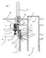
- Fig. 1 shows a fragmentary view of a device 1 according to the invention for closing containers (not shown).
- This device 1 has a closing device designated in its entirety by 2, which attaches closures to the containers.
- this is a closure device which unscrews the closures on the containers.
- the closure device 2 is movable along the double arrow P or along a longitudinal direction of the containers.
- the closure device 2 is arranged completely within a sterile room or clean room 4.
- the closure device 2 has a closure head 22 which is rotatably arranged.
- the closure device 2 has a carrier 23, within which the closure head 22 is rotatably mounted.
- the closure device For rotation of the closure head 22, the closure device on a drive gear 28, which in turn is driven by a driven gear 26.
- This drive wheel 28 and the output gear 26 are here completely within the clean room 4.
- the output gear 26 is of a drive device 24 such an electric motor driven, said drive means 24 is arranged outside of the clean room 4.
- the closure device 2 is supplied with closures by a feed device (not shown).
- the reference numeral 27 refers to a suspension device which biases the closure head in the direction of the containers (not shown). These containers can be brought to the closure head 22 by means of a transport device (not shown), such as a transport star.
- the drive wheel 28 is displaceable relative to the output gear 26 in the longitudinal direction L, without being disengaged from this output gear.
- the drive wheel 28 along the entire stroke of the closure device 2 relative to the driven gear is movable, which can be achieved in that one of the two wheels 26, 28 relative to the other wheel 28, 26 has a significantly greater length 1 in the longitudinal direction L.
- the length of one of the two wheels 26, 28 and here of the output gear 26 is at least as large as the stroke of the closure device 2.
- the reference numeral 14 refers to an upper limit of the sterile room. It is possible that the device according to the invention has a multiplicity of drive devices and closure devices 2. In this case, in particular a plurality of closure devices can be arranged on a rotatable shaft 36. An outer circumference 8 of this shaft 36 can also form a boundary wall of the sterile room 4. The shaft 36 itself may be sealed by a cover 38 sterile.
- the reference numeral 18 refers to a guide device which is stationary in the longitudinal direction L and which guides a movement of the closure device 2 along the double arrow P.
- this guide means 18 is preferably arranged completely within the clean room 4.
- the output gear 26 is here designed as an elongated gear which extends along the region 1, i. The individual teeth of this output gear 26 also have the illustrated length 1.
- the closure device 2 is fixedly arranged on a support 6, this support both inside the clean room 4 and outside the clean room 4, i. is arranged in an environment 18.
- the reference numeral 12 refers to a lower wall, through which the clean room 4 is also limited, and through which the carrier 6 extends.
- the reference numeral 10 refers to an at least partially in Fig. 1 completely within the sterile chamber 4 arranged sealing means, such as a bellows, which is also in the direction L elastic or stretchable. That region 6a of the carrier 6, which is temporarily arranged inside and temporarily outside the clean room, is completely covered by this bellows 10. Furthermore, the carrier is guided by means of a guide bush 25 or the movement of the carrier 6 is stored. Above this bellows, however, at any time within the sterile room 4, a connection 11 is arranged, on which in turn the closure device 2 is fixedly arranged. The bellows is here completely arranged within the sterile room 4.
- sealing means such as a bellows, which is also in the direction L elastic or stretchable. That region 6a of the carrier 6, which is temporarily arranged inside and temporarily outside the clean room, is completely covered by this bellows 10. Furthermore, the carrier is guided by means of a guide bush 25 or the movement of the carrier 6 is stored. Above this bellows, however, at any time within the sterile
- the bellows 10 is compressed or expanded.
- the volume between the bellows and the outer circumference of the carrier 6 changes.
- a vent slot 32 is provided in the guide bushing 25 so that the volume change along the arrow P1 resulting from the movement of the carrier 6 from the device into the non-sterile Room 16 can be executed.
- the reference symbol T marks a dividing line between a sterile area arranged above this line T and an unsterile area arranged below this line T. At the height of this dividing line T, the mouths of the containers to be closed are essentially arranged during the working operation.
- Fig. 2 shows a further embodiment of a device according to the invention 1.
- the in Fig. 2 The embodiment shown differs from that in FIG Fig. 1 shown embodiment by the discharge of the resulting air through a side channel 34 (arrow P2), in turn, the venting slot 32 opens.
- This side channel is disposed outside of the sleeve 25.
- the reference numeral 35 refers to another passage for discharging the air, which passage adjoins the side passage 34.
- the reference numeral 42 refers to a channel and in particular a suction channel, which is arranged in a region of an output shaft 44, which transmits the rotational movement of the drive device 24 to the output gear 26.
- a gaseous medium and in particular a hydrogen peroxide gas-air mixture can be sucked directly to the output shaft or motor shaft 44.
- the device comprises a housing or a cylindrical body 46, within which the output shaft 44 extends, or within which this output shaft 44 rotates.
- the rotational movement for the closure head 22 is also generated outside the clean room and transmitted through the support plate to the located in the clean room closure heads 22 here. Of the Channel extends into the housing 46 inside.
- a small annular gap 48 preferably provided with a splash guard lip. This annular gap prevents a direct jet on the drive device 24.
- the channel 42 connects. Penetrating liquid trickles down again. Furthermore, aerosols flowing in during the cleaning can be sucked off via the suction channel 42 as required.
- the housing may be formed integrally with the boundary wall 14 of the sterile room, but preferably the housing is inserted into the boundary wall of the sterile room. In this case, this housing 46 extends through the boundary wall 14 therethrough. In this case, the housing 46 may have a collar 49, which is supported against the boundary wall 14.
- an active suction can be omitted preferably, since a continuous overflow to the outside takes place as a result of an overpressure in the sterile room.
- aspiration should be performed during sterilization, as otherwise the MAK values for H 2 O 2 could be exceeded in the operator area.
- This embodiment also has the advantage that it is possible to dispense with abrasive seals, vapor barriers or fluid locks.
Landscapes
- Engineering & Computer Science (AREA)
- Mechanical Engineering (AREA)
- Sealing Of Jars (AREA)
- Closing Of Containers (AREA)
- Apparatus For Disinfection Or Sterilisation (AREA)
- Closures For Containers (AREA)
Claims (14)
- Installation (1) pour le bouchage de récipients au moyen d'un dispositif de bouchage (2) appliquant des bouchons sur les récipients, ledit dispositif de bouchage (2) comportant une tête de fermeture (22) mobile pour l'application de bouchons sur les récipients, étant situé à l'intérieur d'un espace stérile (4) de l'installation (1) et étant déplaçable dans une direction longitudinale (L) des récipients à boucher, et au moins une paroi étant prévue, laquelle délimite l'espace stérile (4), le dispositif de bouchage (2) étant disposé sur un support (6) situé partiellement à l'intérieur de l'espace stérile (4) et partiellement à l'extérieur de l'espace stérile (4), et étant déplaçable en direction longitudinale (L) par rapport à l'espace stérile (4), un premier élément d'étanchéité (10) élastique étant disposé dans la direction longitudinale (L) à l'intérieur de l'espace stérile (4), lequel rend étanche une partie (6a) de la périphérie extérieure du support (6) par rapport à l'espace stérile (4),
caractérisée en ce qu'
un dispositif de guidage (18) est situé à l'intérieur de l'espace stérile (4), lequel guide un déplacement de la tête de fermeture dans la direction longitudinale (L). - Installation (1) selon la revendication 1, caractérisée en ce qu'
un volume est formé entre le premier élément d'étanchéité (10) et la partie (6a) de la périphérie extérieure du support (6) en fonction d'une position du support (6) dans la direction longitudinale (L), et en ce que ledit volume est en liaison d'écoulement avec un espace (16) géométriquement situé à l'extérieur de l'espace stérile (4). - Installation (1) selon au moins une des revendications précédentes, caractérisée en ce que
la partie (6a) de la périphérie extérieure du support (6) est en fonctionnement de l'installation située temporairement à l'intérieur de l'espace stérile (4) et temporairement à l'extérieur de l'espace stérile (4). - Installation (1) selon au moins une des revendications précédentes, caractérisée en ce que
l'élément d'étanchéité (10) est un soufflet (10) s'étendant autour de la périphérie extérieure du support (6). - Installation (1) selon au moins une des revendications précédentes, caractérisée en ce que
le dispositif de bouchage (2) comporte une tête de fermeture (22) rotative pour le vissage des bouchons sur les récipients. - Installation (1) selon la revendication 5, caractérisée en ce qu'
un dispositif d'entraînement (24) destiné à entraîner la tête de fermeture (22) est situé à l'extérieur de l'espace stérile (4). - Installation (1) selon la revendication 6, caractérisée en ce que
ladite installation comporte une roue secondaire (26) entraînée par le dispositif d'entraînement (24), laquelle entraîne une roue d'entraînement (28) fixement raccordée à la tête de fermeture, des dents d'au moins la roue d'entraînement et/ou de la roue secondaire s'étendant dans la direction longitudinale (L) du récipient. - Installation (1) selon au moins une des revendications précédentes, caractérisée en ce que
ladite installation (1) comprend un dispositif de transport, lequel transporte les récipients à l'intérieur de l'espace stérile (4). - Installation (1) selon au moins une des revendications précédentes, caractérisée en ce que
ladite installation comporte un deuxième élément d'étanchéité (30) élastique dans la direction longitudinale (L), lequel est situé au moins temporairement à l'extérieur de l'espace stérile (4). - Installation (1) selon la revendication 9, caractérisée en ce que
le deuxième élément d'étanchéité (30) élastique est un soufflet. - Installation (1) selon au moins une des revendications 9 et 10, caractérisée en ce qu'
un volume formé entre le premier élément d'étanchéité (10) et le support (6) dans une première position du support (6) correspond sensiblement au volume formé entre le deuxième élément d'étanchéité (30) et le support (6) dans une deuxième position du support (6). - Installation (1) selon au moins une des revendications précédentes, caractérisée en ce que
le déplacement du support (6) est commandé par une came de guidage située à l'extérieur de l'espace stérile (4). - Installation (1) selon la revendication 12, caractérisée en ce que
l'espace stérile (4) est situé entre la came de guidage et le dispositif d'entraînement (24). - Installation (1) pour le bouchage de récipients selon au moins une des revendications précédentes, avec un dispositif d'entraînement (24) destiné à entraîner la tête de fermeture, ledit dispositif d'entraînement (24) étant situé à l'extérieur de l'espace stérile (4), et ladite installation (1) comportant un arbre de sortie (44) rotatif entraîné par le dispositif d'entraînement (24) pour l'entraînement de la tête de fermeture (22), ledit arbre de sortie (44) s'étendant au travers de la paroi de délimitation (14) de l'espace stérile, et un boîtier étant prévu, lequel entoure ledit arbre de sortie (44), un canal (42) étant en outre prévu pour évacuer du boîtier (46) un fluide notamment gazeux.
Applications Claiming Priority (1)
| Application Number | Priority Date | Filing Date | Title |
|---|---|---|---|
| DE102008056241A DE102008056241A1 (de) | 2008-11-06 | 2008-11-06 | Verschlussvorrichtung für Behältnisse |
Publications (3)
| Publication Number | Publication Date |
|---|---|
| EP2186770A2 EP2186770A2 (fr) | 2010-05-19 |
| EP2186770A3 EP2186770A3 (fr) | 2010-08-04 |
| EP2186770B1 true EP2186770B1 (fr) | 2014-04-09 |
Family
ID=41651338
Family Applications (1)
| Application Number | Title | Priority Date | Filing Date |
|---|---|---|---|
| EP09173764.3A Active EP2186770B1 (fr) | 2008-11-06 | 2009-10-22 | Dispositif de bouchage de récipients |
Country Status (5)
| Country | Link |
|---|---|
| US (2) | US8375684B2 (fr) |
| EP (1) | EP2186770B1 (fr) |
| JP (1) | JP5398480B2 (fr) |
| CN (1) | CN101734598B (fr) |
| DE (1) | DE102008056241A1 (fr) |
Families Citing this family (13)
| Publication number | Priority date | Publication date | Assignee | Title |
|---|---|---|---|---|
| DE102008056242A1 (de) * | 2008-11-06 | 2010-05-12 | Krones Ag | Verschlussvorrichtung für Behältnisse mit Sterilraum |
| DE102009009822A1 (de) | 2009-02-20 | 2010-08-26 | Krones Ag | Vorrichtung zum Verschließen von Behältnissen mit berührungsloser Drehmomentenerzeugung |
| DE102010022128B4 (de) * | 2010-05-20 | 2012-03-15 | Krones Aktiengesellschaft | Vorrichtung zum Umformen von Kunststoffvorformlingen mit Sterilraum |
| DE102010049026A1 (de) * | 2010-10-21 | 2012-06-21 | Krones Aktiengesellschaft | Transfersternim Reinraum |
| DE102011108429A1 (de) * | 2011-07-26 | 2013-01-31 | Khs Gmbh | Vorrichtung zum Verschließen von Behältern |
| DE102011108428A1 (de) * | 2011-07-26 | 2013-01-31 | Khs Gmbh | Vorrichtung zum Verschließen von Behältern |
| DE102012103522A1 (de) | 2012-04-20 | 2013-10-24 | Krones Ag | Faltenbalg |
| EP2889260B1 (fr) * | 2013-12-30 | 2016-03-09 | Sidel S.p.a. Con Socio Unico | Unité pour exécuter une opération sur un récipient pouvant être rempli avec un produit coulant |
| JP6535487B2 (ja) * | 2015-03-18 | 2019-06-26 | あおい精機株式会社 | 閉栓装置、閉栓ユニット及び閉栓方法 |
| EP3316915B1 (fr) * | 2015-07-02 | 2019-11-13 | Xenex Disinfection Services Inc. | Appareils germicides conçus pour mettre en uvre sélectivement différents modes de désinfection à l'intérieur et à l'extérieur de l'appareil |
| CN105082051B (zh) * | 2015-08-31 | 2017-06-06 | 重庆开奇科技发展有限公司 | 采血管单只流水旋转生产装置 |
| EP3750845B1 (fr) * | 2019-06-10 | 2024-08-28 | Sidel Participations, S.A.S. | Machine de capsulage pour l'application de capsules sur des récipients dans des conditions aseptiques ou ultra propres |
| CN111924159A (zh) * | 2020-08-04 | 2020-11-13 | 安徽锴珑电子科技有限公司 | 一种储料桶的上盖旋紧装置 |
Family Cites Families (27)
| Publication number | Priority date | Publication date | Assignee | Title |
|---|---|---|---|---|
| US623472A (en) * | 1899-04-18 | Bottle-package | ||
| US2423358A (en) * | 1944-09-21 | 1947-07-01 | Owens Illinois Glass Co | Method of packaging granular materials |
| US2931147A (en) * | 1956-07-03 | 1960-04-05 | Owens Illinois Glass Co | Method and apparatus for excluding air in packaging powdered materials |
| DE1262445B (de) | 1959-12-11 | 1968-03-07 | Gen Electric | Doppelendige elektrische Gluehlampe |
| DE1905728A1 (de) | 1969-02-06 | 1970-08-20 | Hermann Borgers | Betonformstueck fuer einen Strassenablauf |
| US4240242A (en) * | 1979-06-18 | 1980-12-23 | Grey Charles M | Sterile capping method for a plurality of I.V. bottles |
| JPH01150502U (fr) * | 1988-04-07 | 1989-10-18 | ||
| FR2646833B1 (fr) | 1989-05-12 | 1991-11-22 | Torterotot Roland | Dispositif ecran pour organe de commande et application de ce dispositif a un doseur-distributeur |
| FR2665767B1 (fr) * | 1990-08-08 | 1994-12-23 | Jagenberg Ag | Procede et dispositif de reglage des quantites de produit dosees et distribuees par un doseur-distributeur. |
| DE4226797A1 (de) | 1992-08-13 | 1994-02-17 | Gea Finnah Gmbh | Verfahren und Maschine zur aseptischen Abfüllung von Nahrungs- oder Genußmitteln |
| DE4304220C2 (de) * | 1993-02-12 | 1997-09-18 | Tetra Laval Holdings & Finance | Verfahren zum Sterilisieren und Füllen von Fließmittelpackungen, Vorrichtung hierfür und Verwendung bei einer besonderen Packung |
| US5528879A (en) | 1995-05-26 | 1996-06-25 | Diversified Capping Equipment, Inc. | Apparatus for applying closures to containers |
| JPH0940082A (ja) * | 1995-07-26 | 1997-02-10 | Shibuya Kogyo Co Ltd | 無菌システム用キャッパ |
| US5848515A (en) * | 1995-08-11 | 1998-12-15 | Rossi & Catelli S.P.A. | Continuous-cycle sterile bottling plant |
| IT1279846B1 (it) * | 1995-08-11 | 1997-12-18 | Rossi & Catelli Spa | Impianto di imbottigliamento asettico in continuo |
| DE19806520A1 (de) | 1998-02-17 | 1999-08-19 | Ruediger Haaga Gmbh | Verfahren zum Sterilisieren, Befüllen und Verschließen von Behältern |
| US6082418A (en) * | 1998-06-10 | 2000-07-04 | Crown Simplimatic Incorporated | Aseptic container filling assembly |
| DE10008426B4 (de) * | 2000-02-23 | 2011-07-28 | KHS GmbH, 44143 | System sowie Verfahren zum Füllen von Behältern mit einem flüssigen Füllgut |
| DE60104526T2 (de) | 2001-05-30 | 2005-08-04 | Procomac S.P.A., Sala Baganza | Verschliesskopf mit Spindelsterilisator |
| ITPR20030001A1 (it) * | 2003-01-17 | 2004-07-18 | Sig Technology Ltd | Macchina per il trattamento in asettico di contenitori |
| DE10340365A1 (de) * | 2003-09-02 | 2005-03-24 | Khs Maschinen- Und Anlagenbau Ag | Vorrichtung zum Wechseln von an umlaufenden Behälterbehandlungsmaschinen angeordneten Bauteilen |
| DE10342415A1 (de) * | 2003-09-13 | 2005-04-07 | Khs Maschinen- Und Anlagenbau Ag | Behälterbehandlungsmaschine |
| GB0503019D0 (en) * | 2005-02-12 | 2005-03-16 | Elopak Systems | Dosing apparatus |
| DE102005032322A1 (de) * | 2005-07-08 | 2007-01-11 | Sig Technology Ag | Verfahren und Maschine zum Verschließen von Flaschen mit sterilen Kappen |
| DE202006003975U1 (de) * | 2006-03-14 | 2007-07-19 | Krones Ag | Schraubverschließer für Flaschen o.dgl. |
| ITTO20060699A1 (it) * | 2006-09-29 | 2008-03-30 | Arol Spa | "testa di chiusura per una macchina tappatrice automatica" |
| DE102008026632A1 (de) * | 2008-06-04 | 2009-12-10 | Khs Ag | Verschließmaschine |
-
2008
- 2008-11-06 DE DE102008056241A patent/DE102008056241A1/de not_active Withdrawn
-
2009
- 2009-10-22 EP EP09173764.3A patent/EP2186770B1/fr active Active
- 2009-11-04 CN CN200910212215.9A patent/CN101734598B/zh active Active
- 2009-11-05 US US12/613,407 patent/US8375684B2/en active Active
- 2009-11-05 JP JP2009254233A patent/JP5398480B2/ja active Active
-
2013
- 2013-01-07 US US13/735,662 patent/US8720164B2/en active Active
Also Published As
| Publication number | Publication date |
|---|---|
| US8375684B2 (en) | 2013-02-19 |
| EP2186770A2 (fr) | 2010-05-19 |
| CN101734598A (zh) | 2010-06-16 |
| US8720164B2 (en) | 2014-05-13 |
| US20130133287A1 (en) | 2013-05-30 |
| CN101734598B (zh) | 2014-01-22 |
| JP5398480B2 (ja) | 2014-01-29 |
| EP2186770A3 (fr) | 2010-08-04 |
| JP2010111438A (ja) | 2010-05-20 |
| DE102008056241A1 (de) | 2010-05-12 |
| US20100126116A1 (en) | 2010-05-27 |
Similar Documents
| Publication | Publication Date | Title |
|---|---|---|
| EP2186770B1 (fr) | Dispositif de bouchage de récipients | |
| EP1529751B1 (fr) | Machine pour fermer des récipients | |
| EP2344410B1 (fr) | Dispositif de fermeture pour conteneurs avec espace stérile | |
| EP2958848B1 (fr) | Dispositif et machine pour la fermeture des recipients | |
| EP0582955B1 (fr) | Dispositif pour doser et remplir des produits liquides ou pâteux, spécialement pour remplir des produits sélectionnés, comme par exemple du yaourt aux fruits ou similaire, de préférence sur des machines aseptiques à plusieurs voies | |
| WO2010118806A2 (fr) | Dispositif de fermeture pour capsules ou fermetures filetées | |
| EP2489627B1 (fr) | Installation de traitement de récipients dotée d'un passage de mur aseptique | |
| DE102009008138A1 (de) | Transportsystem für Flaschen oder dergleichen Behälter | |
| WO2009146823A1 (fr) | Machine de fermeture | |
| EP1514835A1 (fr) | Machine de traitement de récipients | |
| EP2751016A1 (fr) | Élément de levage doté d'une douille de rinçage rétractable | |
| EP2465545B1 (fr) | Dispositif de stérilisation de récipients | |
| EP2719655B1 (fr) | Dispositif de traitement de récipients et procédé de nettoyage pour un tel dispositif | |
| EP2900590B1 (fr) | Machine de remplissage | |
| EP2328829B1 (fr) | Machine de traitement de récipients, notamment machine à capsuler | |
| EP2847123B1 (fr) | Remplisseuse | |
| EP3554987B1 (fr) | Ensemble élément de remplissage et machine de remplissage | |
| EP3331812B1 (fr) | Procédé de nettoyage et/ou de désinfection d'éléments de fermeture et machine de fermeture | |
| EP2881360A1 (fr) | Dispositif de traitement d'un récipient dans une installation de remplissage de boissons et procédé de nettoyage du dispositif | |
| EP2387543A2 (fr) | Machine de traitement de récipients | |
| WO2010060587A2 (fr) | Dispositif et procédé pour traiter des bouteilles ou des contenants similaires | |
| WO2023046458A1 (fr) | Dispositif de fermeture pour récipients | |
| WO2021121917A1 (fr) | Machine de remplissage | |
| DE102013101812A1 (de) | Füllsystem sowie Füllmaschine |
Legal Events
| Date | Code | Title | Description |
|---|---|---|---|
| PUAI | Public reference made under article 153(3) epc to a published international application that has entered the european phase |
Free format text: ORIGINAL CODE: 0009012 |
|
| AK | Designated contracting states |
Kind code of ref document: A2 Designated state(s): AT BE BG CH CY CZ DE DK EE ES FI FR GB GR HR HU IE IS IT LI LT LU LV MC MK MT NL NO PL PT RO SE SI SK SM TR |
|
| AX | Request for extension of the european patent |
Extension state: AL BA RS |
|
| PUAL | Search report despatched |
Free format text: ORIGINAL CODE: 0009013 |
|
| AK | Designated contracting states |
Kind code of ref document: A3 Designated state(s): AT BE BG CH CY CZ DE DK EE ES FI FR GB GR HR HU IE IS IT LI LT LU LV MC MK MT NL NO PL PT RO SE SI SK SM TR |
|
| AX | Request for extension of the european patent |
Extension state: AL BA RS |
|
| 17P | Request for examination filed |
Effective date: 20110204 |
|
| GRAP | Despatch of communication of intention to grant a patent |
Free format text: ORIGINAL CODE: EPIDOSNIGR1 |
|
| INTG | Intention to grant announced |
Effective date: 20131025 |
|
| GRAS | Grant fee paid |
Free format text: ORIGINAL CODE: EPIDOSNIGR3 |
|
| GRAA | (expected) grant |
Free format text: ORIGINAL CODE: 0009210 |
|
| AK | Designated contracting states |
Kind code of ref document: B1 Designated state(s): AT BE BG CH CY CZ DE DK EE ES FI FR GB GR HR HU IE IS IT LI LT LU LV MC MK MT NL NO PL PT RO SE SI SK SM TR |
|
| REG | Reference to a national code |
Ref country code: GB Ref legal event code: FG4D Free format text: NOT ENGLISH |
|
| REG | Reference to a national code |
Ref country code: CH Ref legal event code: EP Ref country code: AT Ref legal event code: REF Ref document number: 661247 Country of ref document: AT Kind code of ref document: T Effective date: 20140415 |
|
| REG | Reference to a national code |
Ref country code: IE Ref legal event code: FG4D Free format text: LANGUAGE OF EP DOCUMENT: GERMAN |
|
| REG | Reference to a national code |
Ref country code: DE Ref legal event code: R096 Ref document number: 502009009138 Country of ref document: DE Effective date: 20140522 |
|
| REG | Reference to a national code |
Ref country code: NL Ref legal event code: VDEP Effective date: 20140409 |
|
| REG | Reference to a national code |
Ref country code: LT Ref legal event code: MG4D |
|
| PG25 | Lapsed in a contracting state [announced via postgrant information from national office to epo] |
Ref country code: LT Free format text: LAPSE BECAUSE OF FAILURE TO SUBMIT A TRANSLATION OF THE DESCRIPTION OR TO PAY THE FEE WITHIN THE PRESCRIBED TIME-LIMIT Effective date: 20140409 Ref country code: BG Free format text: LAPSE BECAUSE OF FAILURE TO SUBMIT A TRANSLATION OF THE DESCRIPTION OR TO PAY THE FEE WITHIN THE PRESCRIBED TIME-LIMIT Effective date: 20140709 Ref country code: IS Free format text: LAPSE BECAUSE OF FAILURE TO SUBMIT A TRANSLATION OF THE DESCRIPTION OR TO PAY THE FEE WITHIN THE PRESCRIBED TIME-LIMIT Effective date: 20140809 Ref country code: GR Free format text: LAPSE BECAUSE OF FAILURE TO SUBMIT A TRANSLATION OF THE DESCRIPTION OR TO PAY THE FEE WITHIN THE PRESCRIBED TIME-LIMIT Effective date: 20140710 Ref country code: FI Free format text: LAPSE BECAUSE OF FAILURE TO SUBMIT A TRANSLATION OF THE DESCRIPTION OR TO PAY THE FEE WITHIN THE PRESCRIBED TIME-LIMIT Effective date: 20140409 Ref country code: NO Free format text: LAPSE BECAUSE OF FAILURE TO SUBMIT A TRANSLATION OF THE DESCRIPTION OR TO PAY THE FEE WITHIN THE PRESCRIBED TIME-LIMIT Effective date: 20140709 Ref country code: NL Free format text: LAPSE BECAUSE OF FAILURE TO SUBMIT A TRANSLATION OF THE DESCRIPTION OR TO PAY THE FEE WITHIN THE PRESCRIBED TIME-LIMIT Effective date: 20140409 |
|
| PG25 | Lapsed in a contracting state [announced via postgrant information from national office to epo] |
Ref country code: ES Free format text: LAPSE BECAUSE OF FAILURE TO SUBMIT A TRANSLATION OF THE DESCRIPTION OR TO PAY THE FEE WITHIN THE PRESCRIBED TIME-LIMIT Effective date: 20140409 Ref country code: PL Free format text: LAPSE BECAUSE OF FAILURE TO SUBMIT A TRANSLATION OF THE DESCRIPTION OR TO PAY THE FEE WITHIN THE PRESCRIBED TIME-LIMIT Effective date: 20140409 Ref country code: SE Free format text: LAPSE BECAUSE OF FAILURE TO SUBMIT A TRANSLATION OF THE DESCRIPTION OR TO PAY THE FEE WITHIN THE PRESCRIBED TIME-LIMIT Effective date: 20140409 Ref country code: LV Free format text: LAPSE BECAUSE OF FAILURE TO SUBMIT A TRANSLATION OF THE DESCRIPTION OR TO PAY THE FEE WITHIN THE PRESCRIBED TIME-LIMIT Effective date: 20140409 Ref country code: HR Free format text: LAPSE BECAUSE OF FAILURE TO SUBMIT A TRANSLATION OF THE DESCRIPTION OR TO PAY THE FEE WITHIN THE PRESCRIBED TIME-LIMIT Effective date: 20140409 |
|
| PG25 | Lapsed in a contracting state [announced via postgrant information from national office to epo] |
Ref country code: PT Free format text: LAPSE BECAUSE OF FAILURE TO SUBMIT A TRANSLATION OF THE DESCRIPTION OR TO PAY THE FEE WITHIN THE PRESCRIBED TIME-LIMIT Effective date: 20140811 |
|
| REG | Reference to a national code |
Ref country code: DE Ref legal event code: R097 Ref document number: 502009009138 Country of ref document: DE |
|
| PG25 | Lapsed in a contracting state [announced via postgrant information from national office to epo] |
Ref country code: CZ Free format text: LAPSE BECAUSE OF FAILURE TO SUBMIT A TRANSLATION OF THE DESCRIPTION OR TO PAY THE FEE WITHIN THE PRESCRIBED TIME-LIMIT Effective date: 20140409 Ref country code: RO Free format text: LAPSE BECAUSE OF FAILURE TO SUBMIT A TRANSLATION OF THE DESCRIPTION OR TO PAY THE FEE WITHIN THE PRESCRIBED TIME-LIMIT Effective date: 20140409 Ref country code: SK Free format text: LAPSE BECAUSE OF FAILURE TO SUBMIT A TRANSLATION OF THE DESCRIPTION OR TO PAY THE FEE WITHIN THE PRESCRIBED TIME-LIMIT Effective date: 20140409 Ref country code: EE Free format text: LAPSE BECAUSE OF FAILURE TO SUBMIT A TRANSLATION OF THE DESCRIPTION OR TO PAY THE FEE WITHIN THE PRESCRIBED TIME-LIMIT Effective date: 20140409 Ref country code: DK Free format text: LAPSE BECAUSE OF FAILURE TO SUBMIT A TRANSLATION OF THE DESCRIPTION OR TO PAY THE FEE WITHIN THE PRESCRIBED TIME-LIMIT Effective date: 20140409 |
|
| PLBE | No opposition filed within time limit |
Free format text: ORIGINAL CODE: 0009261 |
|
| STAA | Information on the status of an ep patent application or granted ep patent |
Free format text: STATUS: NO OPPOSITION FILED WITHIN TIME LIMIT |
|
| 26N | No opposition filed |
Effective date: 20150112 |
|
| REG | Reference to a national code |
Ref country code: DE Ref legal event code: R097 Ref document number: 502009009138 Country of ref document: DE Effective date: 20150112 |
|
| PG25 | Lapsed in a contracting state [announced via postgrant information from national office to epo] |
Ref country code: MC Free format text: LAPSE BECAUSE OF FAILURE TO SUBMIT A TRANSLATION OF THE DESCRIPTION OR TO PAY THE FEE WITHIN THE PRESCRIBED TIME-LIMIT Effective date: 20140409 Ref country code: LU Free format text: LAPSE BECAUSE OF FAILURE TO SUBMIT A TRANSLATION OF THE DESCRIPTION OR TO PAY THE FEE WITHIN THE PRESCRIBED TIME-LIMIT Effective date: 20141022 |
|
| REG | Reference to a national code |
Ref country code: CH Ref legal event code: PL |
|
| GBPC | Gb: european patent ceased through non-payment of renewal fee |
Effective date: 20141022 |
|
| PG25 | Lapsed in a contracting state [announced via postgrant information from national office to epo] |
Ref country code: BE Free format text: LAPSE BECAUSE OF NON-PAYMENT OF DUE FEES Effective date: 20141031 |
|
| REG | Reference to a national code |
Ref country code: IE Ref legal event code: MM4A |
|
| PG25 | Lapsed in a contracting state [announced via postgrant information from national office to epo] |
Ref country code: SI Free format text: LAPSE BECAUSE OF FAILURE TO SUBMIT A TRANSLATION OF THE DESCRIPTION OR TO PAY THE FEE WITHIN THE PRESCRIBED TIME-LIMIT Effective date: 20140409 Ref country code: GB Free format text: LAPSE BECAUSE OF NON-PAYMENT OF DUE FEES Effective date: 20141022 Ref country code: LI Free format text: LAPSE BECAUSE OF NON-PAYMENT OF DUE FEES Effective date: 20141031 Ref country code: CH Free format text: LAPSE BECAUSE OF NON-PAYMENT OF DUE FEES Effective date: 20141031 |
|
| PG25 | Lapsed in a contracting state [announced via postgrant information from national office to epo] |
Ref country code: IE Free format text: LAPSE BECAUSE OF NON-PAYMENT OF DUE FEES Effective date: 20141022 |
|
| REG | Reference to a national code |
Ref country code: AT Ref legal event code: MM01 Ref document number: 661247 Country of ref document: AT Kind code of ref document: T Effective date: 20141022 |
|
| PG25 | Lapsed in a contracting state [announced via postgrant information from national office to epo] |
Ref country code: AT Free format text: LAPSE BECAUSE OF NON-PAYMENT OF DUE FEES Effective date: 20141022 |
|
| PG25 | Lapsed in a contracting state [announced via postgrant information from national office to epo] |
Ref country code: SM Free format text: LAPSE BECAUSE OF FAILURE TO SUBMIT A TRANSLATION OF THE DESCRIPTION OR TO PAY THE FEE WITHIN THE PRESCRIBED TIME-LIMIT Effective date: 20140409 |
|
| PG25 | Lapsed in a contracting state [announced via postgrant information from national office to epo] |
Ref country code: CY Free format text: LAPSE BECAUSE OF FAILURE TO SUBMIT A TRANSLATION OF THE DESCRIPTION OR TO PAY THE FEE WITHIN THE PRESCRIBED TIME-LIMIT Effective date: 20140409 |
|
| PG25 | Lapsed in a contracting state [announced via postgrant information from national office to epo] |
Ref country code: HU Free format text: LAPSE BECAUSE OF FAILURE TO SUBMIT A TRANSLATION OF THE DESCRIPTION OR TO PAY THE FEE WITHIN THE PRESCRIBED TIME-LIMIT; INVALID AB INITIO Effective date: 20091022 Ref country code: MT Free format text: LAPSE BECAUSE OF FAILURE TO SUBMIT A TRANSLATION OF THE DESCRIPTION OR TO PAY THE FEE WITHIN THE PRESCRIBED TIME-LIMIT Effective date: 20140409 Ref country code: TR Free format text: LAPSE BECAUSE OF FAILURE TO SUBMIT A TRANSLATION OF THE DESCRIPTION OR TO PAY THE FEE WITHIN THE PRESCRIBED TIME-LIMIT Effective date: 20140409 |
|
| REG | Reference to a national code |
Ref country code: FR Ref legal event code: PLFP Year of fee payment: 8 |
|
| REG | Reference to a national code |
Ref country code: FR Ref legal event code: PLFP Year of fee payment: 9 |
|
| PG25 | Lapsed in a contracting state [announced via postgrant information from national office to epo] |
Ref country code: MK Free format text: LAPSE BECAUSE OF FAILURE TO SUBMIT A TRANSLATION OF THE DESCRIPTION OR TO PAY THE FEE WITHIN THE PRESCRIBED TIME-LIMIT Effective date: 20140409 |
|
| REG | Reference to a national code |
Ref country code: FR Ref legal event code: PLFP Year of fee payment: 10 |
|
| P01 | Opt-out of the competence of the unified patent court (upc) registered |
Effective date: 20230523 |
|
| PGFP | Annual fee paid to national office [announced via postgrant information from national office to epo] |
Ref country code: IT Payment date: 20250922 Year of fee payment: 17 |
|
| PGFP | Annual fee paid to national office [announced via postgrant information from national office to epo] |
Ref country code: FR Payment date: 20250908 Year of fee payment: 17 |
|
| PGFP | Annual fee paid to national office [announced via postgrant information from national office to epo] |
Ref country code: DE Payment date: 20250902 Year of fee payment: 17 |