EP2347486B1 - Kabellegegerät - Google Patents
Kabellegegerät Download PDFInfo
- Publication number
- EP2347486B1 EP2347486B1 EP09785122.4A EP09785122A EP2347486B1 EP 2347486 B1 EP2347486 B1 EP 2347486B1 EP 09785122 A EP09785122 A EP 09785122A EP 2347486 B1 EP2347486 B1 EP 2347486B1
- Authority
- EP
- European Patent Office
- Prior art keywords
- bore
- air
- tube
- fibre
- section
- Prior art date
- Legal status (The legal status is an assumption and is not a legal conclusion. Google has not performed a legal analysis and makes no representation as to the accuracy of the status listed.)
- Active
Links
Images


Classifications
-
- H—ELECTRICITY
- H02—GENERATION; CONVERSION OR DISTRIBUTION OF ELECTRIC POWER
- H02G—INSTALLATION OF ELECTRIC CABLES OR LINES, OR OF COMBINED OPTICAL AND ELECTRIC CABLES OR LINES
- H02G1/00—Methods or apparatus specially adapted for installing, maintaining, repairing or dismantling electric cables or lines
- H02G1/06—Methods or apparatus specially adapted for installing, maintaining, repairing or dismantling electric cables or lines for laying cables, e.g. laying apparatus on vehicle
- H02G1/08—Methods or apparatus specially adapted for installing, maintaining, repairing or dismantling electric cables or lines for laying cables, e.g. laying apparatus on vehicle through tubing or conduit, e.g. rod or draw wire for pushing or pulling
- H02G1/086—Methods or apparatus specially adapted for installing, maintaining, repairing or dismantling electric cables or lines for laying cables, e.g. laying apparatus on vehicle through tubing or conduit, e.g. rod or draw wire for pushing or pulling using fluid as pulling means, e.g. liquid, pressurised gas or suction means
-
- G—PHYSICS
- G02—OPTICS
- G02B—OPTICAL ELEMENTS, SYSTEMS OR APPARATUS
- G02B6/00—Light guides; Structural details of arrangements comprising light guides and other optical elements, e.g. couplings
- G02B6/46—Processes or apparatus adapted for installing or repairing optical fibres or optical cables
- G02B6/50—Underground or underwater installation; Installation through tubing, conduits or ducts
- G02B6/52—Underground or underwater installation; Installation through tubing, conduits or ducts using fluid, e.g. air
Definitions
- the present invention relates to the installation of cables, such as optical fibre units, wires, electrical cables or the like. More specifically, but not exclusively, the present invention relates to the blowing of fibre unit cables through pre-laid conduits.
- Optical fibres are widely used within telecommunication systems for high-speed information transfer.
- a fibre unit which could comprise a single optical fibre, or a bundle of optical fibres, is commonly installed into a protective optical conduit comprising optical fibre tubes, which have already been laid along the desired route, usually as a continuous span between convenient access points such as surface boxes or inspection chambers.
- references to “cables” shall include where the context permits, individual optical fibres and fibre units as well as cables comprising such fibres and fibre units.
- Conduits shall include tubes and tube bores, but in the main refers to the route or path populated or to be populated by a fibre cable, and where the route comprises a number of tubes, the entire length of the route.
- the conduits typically are made of plastic, each with a typical inner diameter of 3 to 6 mm or more, and are usually provided in a bundle comprising up to 24 or more tubes, which are held together within a protective outer sheath.
- Each fibre conduit tube can receive at least one fibre unit comprising one or more individual optical fibres.
- Large numbers of conduits - and bundles of conduits - are pre-installed across the access network and the distribution network between the local exchanges and the customer premises in a branching network system.
- the conduits With the move to pushing fibre links closer to customer premises (e.g. fibre to the premises "FTTP"), the conduits will further extend to and into commercial and residential premises. Indeed it is a fundamental part of the push to FTTP in e.g. the UK that substantially all the network comprises optical fibre, extending from the core network to as many end customers as possible. To achieve this, optical fibre installation needs to be speedy, cost- and effort-efficient.
- SU 1000750 describes a method and apparatus for measuring the average diameter of a number of differently-sized tube sections by measuring the change in air pressure between points along the tube.
- EP 1 832 903 describes an apparatus for detecting the arrival of a fibre unit at the end of a conduit through which air is being blown in order to "blow" the fibre unit through the conduit in order to install the fibre unit into the conduit.
- a frangible diaphragm is provided within the device and is arranged to rupture when the air flowing into the device fills the air-tight space within, the change in air pressure along the entire tube can then be detected at the head end of the tube and is taken as being indicative of a flow of air at the far end of the tube into the device. While there is an obstruction in the form of the diaphragm, there is no comparison of air pressures between two bore sections separated by the obstruction.
- the present invention provides methods and devices relating to the installation of cables such as optical fibre units into conduit tubes, in particular, allowing a single operator to operate substantially on his own to determine if air fed into a conduit is reaching its intended destination, and if the fibre unit subsequently fed into the conduit has reached its destination.
- the invention can be used where the operator has to choose one conduit from a number of possible candidates, or where there is a single conduit but where it is desirable to unambiguously confirm that the air and fibre unit reaches the intended destination.
- a first aspect of the invention provides a device for detecting a flow of air, from an exit end of a tube fed into an entrance end of the tube by a blowing head operable to install a cable into the tube, and for detecting the arrival of a cable at the exit end of the tube, comprising
- an airstone is provided so that air flowing out from the far, exiting, end of the tube can leave the device without any undue build up of pressure within.
- the obstruction provided within the bore causes air within the first section to have a different pressure level from that within the second section. Typically the air pressure level within the first section would be at a higher pressure level that that in the second bore section.
- the obstruction could comprise a physical impediment within the bore, but in a preferred embodiment, this comprises a narrowing portion of the bore that takes the form of a waist or a neck, so that a back pressure is generated in the air flowing from the first bore section to the second.
- the two sections of bore could comprise different, or the same, size in diameter.
- Air pressure measuring points along the bore are also provided to communicate with the two bore sections, which so that pressure differentials between the two sections may be measured e.g. using a pressure sensor or transducer.
- a back pressure is generated by reducing the diameter size of the bore in the direction of air flow from the exit end of the tube towards the airstone, in a preferred embodiment of the device.
- the reducing or narrowing bore size may be restricted to a specific section of the bore, so that the other sections of the bore have a constant diameter along their respective lengths.
- the device is further arranged to detect arrival of a fibre unit or cable as well. This is achieved by providing within the device, preferably along the bore, a retaining section which is configured to prevent the further progress of a fibre bead (which is attached to the leading end of a fibre unit, as described below).
- a sensor is provided at or near to the retaining section which is capable of identifying the presence of the fibre bead. Where the bead is made of a metal, as it usually is, the sensor might comprises an induction coil looped around or about the retaining section within the bore.
- a signalling unit in the form of a radio unit or other telecommunications component may be included to signal the arrival of air and/or fibre to the head end, as well as a microprocessor to assist in the determining and detection of air and/or fibre arrival at the far end.
- a second aspect of the invention provides a method of detecting a flow of air from an exit end of a tube, comprising
- FIG. 1 A simple schematic view of the components used to install optical fibre using the blown fibre technique, is depicted in Figure 1
- a blowing head (2) which comprises mechanical drive means, which push an optical fibre unit or cable into a tube or conduit (6) towards the far end
- the blowing head is aided in this task by pressurised air which is fed into the conduit using an air compressor (4), so that the fibre unit within the conduit is at least in part blown through the conduit
- An "airstone” (8) is fixed to the far end of the conduit This is comprises a barrier of porous compressed granular material, which will allow air to pass through but which will stop the continued progress of the fibre unit beyond the barrier.
- the conventional process involves a first engineer operating the blowing head and the compressor is located at the head end, while a second engineer is sited at the far end.
- the second engineer will signal (10) back to the first operator to confirm (i) that the correct conduit has been selected at the head end, as air from the compressor is flowing out of the desired tube mouth, so that the process may now move to the fibre installation stage, and (ii) that the fibre unit has emerged from the tube mouth, so the installation process may be terminated.
- the signalling may be carried out using any method e.g. by mobile telephone, walkie-talkie or the like.
- FIG. 2 shows in cross section a view of an embodiment of a sensing device (20) according to the invention.
- An airstone (8) made of an air-porous material, is provided within the housing (22) of the device.
- the far end of the tube (6) is fitted to a receiving portion (5) of the device using a conventional interchangeable collet tube connector so that the bore of the tube communicates with the bore (24) of the device leading to the airstone as shown.
- the correct tube or conduit has been chosen at the head end, air eventually flows through the device bore and into the device as shown by the dotted arrows. (Of course, if the wrong tube is selected at the head end, no air will flow into the device.) This air is shown in Figure 2 to pass through the airstone in the known way.
- the sensing device further includes a pressure sensor or transducer (26) which is configured to sense air pressure levels within the bore (24), and any changes in pressure levels.
- the device bore (24) is profiled along its length as shown in Figure 2 , so that it includes a reducing or narrowing portion (32) having a cross section which is reduced relative to the immediately adjacent sections of the bore.
- Two air outlets (28, 30) are provided to communicate with the bore: the first (28) allows air to exit at a point prior to its reaching the narrowing section of the bore, while the second (30) is provided at a point after the narrowing section.
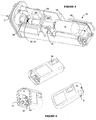
- FIG. 3 Another view of the device (20) is shown in Figure 3 , which depicts parts of the device without its housing, in particular the narrowing section (32) of the bore leading from the receiving portion (5) with which the conduit engages, to the airstone (8) at the opposite end.
- the two air outlets (28, 30) are connected to the pressure transducer (26) by tubes (50). Again, air flow into and from the device are depicted by the dotted arrows.
- the engineer travels to the far end and affixes the device to the mouth of the conduit so that the conduit bore and the device bore communicate, and powers up the device. He then travels to the head end to start the installation process. If the correct conduit has been selected at the head end, air eventually flows from the mouth of the conduit at the far end, and into the bore (24) of the device. Back pressure is generated when air flows through the narrowing section (32) of the bore, and this increases the air pressure level within the bore just before the narrowing portion in the vicinity of the first air outlet (28). In contrast, the air pressure level in the bore the vicinity of the second outlet (30) is likely to be lower owing to its position beyond the narrowing portion (32).
- the pressure transducer is arranged to compare the pressure level P1 of air exiting via first air outlet (28), with the pressure P2 of air exiting via the second air outlet (30). The pressure differential of air detected permits the calculation of an air flow rate within the bore.
- this detected air flow rate deviates from a reference or baseline air flow rate (or a range), it serves as a positive unambiguous indication that air is flowing from the mouth of the conduit and into the device at the far end.
- the baseline value is any which allows for comparison for such purposes, but is preferably calibrated in still air conditions (or else in air which is flowing at a slower rate than the rate being detected). It may be expected that where absence of significant air movement through the bore, the air pressure differential P1 and P2 would be very, or relatively, slight.
- the baseline value may be generated during the installation session itself, upon power-up of the device and before the arrival of air at the far end, when the air within the device is relatively still air within the bore at this stage. More preferably, the calibration process is carried out in stricter still air conditions, e.g. in a controlled environment as part of the production process.
- the baseline value will then be based on the geometry of the specific sensing device, its bore profile and in particular its narrowing portion, which between devices may include dimensional variations.
- the pressure transducer outputs are sent to and monitored by a microprocessor (48). Its function and the steps it goes through is described in detail below against the flow chart of Figure 5 .
- the microprocessor Upon confirmation that the detected air flow rate exceeds or otherwise deviates from the baseline flow value by a predetermined amount, the microprocessor generates a command to a signalling module (34) which confirms to the engineer at the head end that air is flowing from the correct conduit end at the remote end.
- the signalling module sends a mobile telephone message which may take the form of a short message service (SMS) text message, or more preferably be a pre-recorded voice message which would be harder for the head end operator to miss and has higher priority compared to SMS texts.
- SMS short message service
- the engineer may then progress to the next stage of the installation to install the fibre unit.
- Such a bead is typically made of a metal such as brass or aluminium, and it protects the otherwise exposed fibre tip from harm when the fibre is being blown through the conduit, and also when the tip reaches and is contained within the airstone (8).
- the device includes a metal coil (40) which is wound around the device bore at or near its narrowing section (32).
- the coil forms part of an LC oscillator which resonates at a certain constant frequency.
- the coil is ideally calibrated as part of its production process in a way which allows for variations in the tolerances of the sensing devices, and to ensure sufficient sensitivity for reliable bead detection of a variety of metallic bead materials.
- the coil is located at the narrowing section of the device bore, which is dimensioned to prevent further progress of the bead along the device bore. Upon arrival of the fibre and the bead into the device, the bead is lodged and retained in the narrowing section of the bore. Its proximity to the coil acts as a metallic core which changes the inductance of the coil and the Q-value of the oscillator.
- Inductance and Q-value changes cause both frequency and amplitude to vary, so either or both can be monitored and measured using a comparator (although as the change in amplitude is typically greater, it may be easier and preferable to monitor this), to provide a clear indication of fibre arrival at the far end to the operator, which may be signalled back in the same way as described above in connection with the detection of air arrival.
- the induction loop is made of a coil of very fine copper wire having a diameter of about 0.2mm, and the coil will be in the order of 15 turns.
- the exact number of turns is not critical to invention, nor is the size of the wire, although the number of turns used is related to the coil diameter.
- the coil is preferably located at or near the narrowing section of the bore, which serves the dual purpose of reducing the device bore size for purposes of generating a pressure differential detectable as indicating an air flow, as well as serving as a retainer for the fibre unit bead.
- the coil could be located anywhere else within the device as long as it is sufficiently proximate to a location where the fibre bead may be retained e.g. within the airstone, or which it passes allowing for the registration of the momentary or other change in the inductance in the coil indicating that the bead has passed through it.
- the coil responds to the arrival of beads made from various metals such as aluminium, brass, steel or copper.
- bead material types may permit alternative fibre unit arrival detection methods. For example, by substituting the induction coil with a magnetic sensor, the arrival of a bead made of a magnetic material (which need not include metal) or otherwise a ferrous material (any material exhibiting ferro- or para-magnetism properties should be suitable) could be detected as a Hall probe causing a change in the magnetic flux of the magnetic sensor.
- Figure 4 show views of the embodiment of the sensing device (20) described, with its housing (22) on. These views also show the device power-up (42) and power-down (44) buttons as well as a display screen (46).
- the size of the device is about the size of a matchbox (approximately 85 x 60 mm cross section x 180 mm long), within which is fitted the pressure transducer (26), the signalling unit (34), the microprocessor and associated electronics, and the induction coil.
- a power source e.g. a battery
- an antenna for sending confirmatory signals to the head end of the conduit.
- the flow chart in Figure 5 describes the processes to detect and signal both air arrival and fibre unit arrival at the far end of the conduit being populated.
- a microprocessor advantageously undertakes each or both processes although the skilled person would appreciate that a user may be able to manually select the required steps and/or add to the steps, or to override all or part of an automated process undertaken by the processor.
- step S1 the process starts with the operator travelling to the far end and installing the device onto the conduit end, which is then powered up by pressing (step S1) the "start” or “on” button (42), whereupon the device initialises itself (step S2). If it is detected that this is the first power on (step S3), a baseline ("minimum”) air flow value is generated (steps S4, S5) for use in determining if air has arrived at the far end, as described above, by measuring any pressure differential (step S6).
- a preferred implementation includes a step to detect that the air flow within the device bore or cavity has stabilised to a level above the baseline minimum level as being a clear unambiguous sign of air arrival (steps S7, S8) before transmitting a signal of air arrival at the far end (step S9).
- the sensing device is arranged to respond to "test" requests, in the manner shown in the flow chart (steps S10 to S13). It can be recalled that the head and remote ends are a fair distance from each other. This device mode allows the engineer to check that the device is powered on at the far end: he may have forgotten to turn the device on in the first place, or else so much time has elapsed without a signal arriving from the far end that either he is indeed feeding air into the wrong tube, or else the sensing device is not on or otherwise malfunctioning. By pressing the "test” button for an extended period (steps S10, S11), the device at the far end responds (if it can) by sending a response (step S13) to the test message request using the signalling methods described above.
- the session Upon receiving the "air at end” confirmation signal (sent in step S9), the session progresses to the fibre installation stage, wherein the presence of the beaded fibre tip is sensed by detection of a frequency or other change in the inductance coil.
- a confirmatory signal is transmitted to the head end (step S21), and the installation may then be terminated by the engineer by turning off the blowing head and compressor at the head end. He then travels to the remote end to remove the sensing device from the far end.
- an optional receiving device registration process is provided, which enables the engineer's receiving device (e.g. a GSM mobile telephone) to be registered to the sensing device, allowing for signals from the far end to reach the engineer at the head end as shown in the flow chart (steps S23, S24).
- the mobile telephone number or the like is stored in the GSM module and is read initially on power-up of the device, and whenever a serial message is passed from the GSM module to the main sensing device processor indicating that the number has been updated. This message is passed via the serial communications buffer in the microcontroller and checked approximately once a second for possible number updates.
- the installation apparatus may comprise components or elements not explicitly set out above.
- the sensing device may, with appropriate modifications, be fashioned as a sleeve to be used as a connector at intermediate points along the conduit route, for detection of the path taken by the air flow. This allows the operator to track the progress and movement of the air and the fibre unit for purposes in addition to, or other than for, installing blown fibre- such as in the detection of gaps leading to air leaks in the conduit tube network.
Landscapes
- Physics & Mathematics (AREA)
- General Physics & Mathematics (AREA)
- Optics & Photonics (AREA)
- Light Guides In General And Applications Therefor (AREA)
- Electric Cable Installation (AREA)
Claims (12)
- Vorrichtung (20) zur Erfassung eines Luftstroms von einem Austrittsende eines Rohrs (6), der in ein Eintrittsende des Rohrs durch einen Einblaskopf eingeführt wird, der so betreibbar ist, dass er ein Kabel in das Rohr verlegt, sowie zur Erfassung der Ankunft eines Kabels an dem Austrittsende des Rohrs,
die umfasst:- eine Bohrung (24), die einen ersten Bohrungsabschnitt mit einer ersten Bohrungsgröße und einen zweiten Bohrungsabschnitt mit einer zweiten Bohrungsgröße aufweist,dadurch gekennzeichnet, dass die Vorrichtung ferner umfasst:- ein Hindernis (32), das innerhalb der Bohrung zwischen dem ersten Bohrungsabschnitt und dem zweiten Bohrungsabschnitt angeordnet ist, wobei das Hindernis so ausgebildet ist, dass es Luft, die von dem Austrittsende des Rohrs über den ersten Bohrungsabschnitt zu dem zweiten Bohrungsabschnitt strömt, hemmt und eine Faserhülse, die aus dem Austrittsende des Rohrs austritt und in die Bohrung der Vorrichtung eintritt, zurückhält,- eine Befestigungseinrichtung (5) zur Befestigung der Vorrichtung an dem Rohr in der Weise, dass die Bohrung mit dem Austrittsende des Rohrs verbunden ist,- eine Druckvergleichseinheit (26) zum Vergleichen des Drucks der Luft innerhalb des ersten Bohrungsabschnitts mit dem Druck der Luft innerhalb des zweiten Bohrungsabschnitts, so dass eine Druckdifferenz einen Luftstrom im Inneren der Bohrung anzeigt,und- eine Induktionsspule, die einen Teil eines LC-Oszillators darstellt und funktionell an dem Hindernis oder in unmittelbarer Nähe des Hindernisses mit der Vorrichtung verbunden ist, zur Erfassung der Faserhülse innerhalb der Bohrung. - Vorrichtung nach Anspruch 1, die ferner einen ersten Luftauslass (28), der mit dem ersten Bohrungsabschnitt in Verbindung steht, und einen zweiten Luftauslass (30) enthält, der mit dem zweiten Bohrungsabschnitt in Verbindung steht, und bei der die Druckvergleichseinheit im Einsatz den Druck der Luft, die von dem ersten Bohrungsabschnitt über den ersten Luftauslass strömt, und den Druck der Luft, die von dem zweiten Bohrungsabschnitt über den zweiten Luftauslass strömt, vergleicht.
- Vorrichtung nach Anspruch 1 oder Anspruch 2, die ferner eine poröse luftdurchlässige Barriere (8) enthält, die an einem von der Befestigungseinrichtung entfernt liegenden Ende der Bohrung angeordnet ist.
- Vorrichtung nach einem vorhergehenden Anspruch, bei der das Hindernis aus einem verengten Abschnitt der Bohrung besteht.
- Vorrichtung nach einem vorhergehenden Anspruch, bei der die erste Bohrungsgröße von der zweiten Bohrungsgröße verschieden ist.
- Vorrichtung nach einem vorhergehenden Anspruch, die ferner eine Signalisierungseinheit (34) enthält, die so ausgebildet ist, dass sie im Einsatz das Vorliegen eines Luftstroms innerhalb der Bohrung und/oder die Rückhaltung der Faserhülse in dem Rückhaltungsabschnitt an einen entfernten Ort signalisiert.
- Vorrichtung nach Anspruch 6, bei der die Signalisierungseinheit eine mobile GSM-Kommunikationsvorrichtung ist.
- Vorrichtung nach einem vorhergehenden Anspruch, bei der die Druckvergleichseinheit und/oder die Induktionsspule mit einem Prozessor (48) in Wirkverbindung stehen, der dazu ausgebildet ist, den Luftstrom innerhalb der Bohrung zu erfassen.
- Vorrichtung nach Anspruch 8, bei welcher der Prozessor ferner dazu ausgebildet ist, die Signalisierungseinheit zu aktivieren.
- Verfahren zur Erfassung eines Luftstroms von einem Austrittsende eines Rohrs, das umfasst:- Befestigen einer Vorrichtung (20) nach einem vorhergehenden Anspruch an dem Rohr in der Weise, dass eine Bohrung (24) im Inneren der Vorrichtung mit dem Austrittsende des Rohrs (6) in Verbindung steht,- Einführen von Luft in ein Eintrittsende des Rohrs,- Verwenden eines Hindernisses, das innerhalb einer Bohrung der Vorrichtung angeordnet ist, zur Hemmung von Luft, die von dem Austrittsende des Rohrs über einen ersten Bohrungsabschnitt der Vorrichtung in einen zweiten Bohrungsabschnitt strömt,- Vergleichen der Druckniveaus der Luft innerhalb des ersten Bohrungsabschnitts und des zweiten Bohrungsabschnitts,- Signalisieren einer Druckdifferenz aus dem Vergleich als Anzeige eines Luftstroms im Inneren der Bohrung,- Einführen eines Kabels in das Eintrittsende des Rohrs,- Verwenden des Hindernisses zum Zurückhalten einer an dem Kabel angebrachten Faserhülseund- Verwenden einer Induktionsspule, die einen Teil eines LC-Oszillators darstellt und an dem Hindernis oder in unmittelbarer Nähe des Hindernisses funktionell mit der Vorrichtung verbunden ist, zur Erfassung des Vorliegens der Faserhülse innerhalb der Vorrichtung.
- Verfahren nach Anspruch 10, das die Initialisierung der Vorrichtung durch Vergleichen des Drucks der Luft innerhalb des ersten Bohrungsabschnitts und des Drucks der Luft innerhalb des zweiten Bohrungsabschnitts beinhaltet.
- Verfahren nach Anspruch 10 oder Anspruch 11, das ferner beinhaltet:- Einführen einer Fasereinheit mit einer Faserhülse an der Spitze in das Eintrittsende des Rohrs,- Verwenden eines Faserhülsen-Sensors zum Erfassen der Rückhaltung der Faserhülse innerhalb eines Rückhaltungsabschnitts im Inneren der Vorrichtungund- Signalisieren des Vorliegens der Faserhülse innerhalb der Vorrichtung als Anzeige für die Ankunft der Fasereinheit an dem Austrittsende des Rohrs.
Applications Claiming Priority (2)
| Application Number | Priority Date | Filing Date | Title |
|---|---|---|---|
| GBGB0817639.8A GB0817639D0 (en) | 2008-09-26 | 2008-09-26 | Cable installation apparatus |
| PCT/GB2009/002222 WO2010034970A1 (en) | 2008-09-26 | 2009-09-18 | Cable installation apparatus |
Publications (2)
| Publication Number | Publication Date |
|---|---|
| EP2347486A1 EP2347486A1 (de) | 2011-07-27 |
| EP2347486B1 true EP2347486B1 (de) | 2017-04-12 |
Family
ID=40019597
Family Applications (1)
| Application Number | Title | Priority Date | Filing Date |
|---|---|---|---|
| EP09785122.4A Active EP2347486B1 (de) | 2008-09-26 | 2009-09-18 | Kabellegegerät |
Country Status (8)
| Country | Link |
|---|---|
| US (1) | US9774175B2 (de) |
| EP (1) | EP2347486B1 (de) |
| JP (1) | JP2012503790A (de) |
| CN (1) | CN102165658A (de) |
| GB (1) | GB0817639D0 (de) |
| TW (1) | TW201019554A (de) |
| WO (1) | WO2010034970A1 (de) |
| ZA (1) | ZA201101851B (de) |
Families Citing this family (8)
| Publication number | Priority date | Publication date | Assignee | Title |
|---|---|---|---|---|
| EP1914577A1 (de) * | 2006-10-17 | 2008-04-23 | British Telecommunications Public Limited Company | Faseroptisches Installationsgerät |
| EP2075606A1 (de) | 2007-12-28 | 2009-07-01 | British Telecmmunications public limited campany | Kabelinstallation mithilfe von Induktion |
| EP2075608A1 (de) | 2007-12-28 | 2009-07-01 | British Telecmmunications public limited campany | Kabelinstallation mithilfe optischer Erkennung |
| GB0817639D0 (en) | 2008-09-26 | 2008-11-05 | British Telecomm | Cable installation apparatus |
| EP2230545A1 (de) | 2009-03-19 | 2010-09-22 | BRITISH TELECOMMUNICATIONS public limited company | Passive entfernte Luftstrom- und Kabeldetektion |
| GB0905590D0 (en) | 2009-03-31 | 2009-05-13 | British Telecomm | Blown cable apparatus |
| EP2369388A1 (de) | 2010-03-26 | 2011-09-28 | British Telecommunications public limited company | Spleisskassettenmodul für optische Faser |
| DE102023203867A1 (de) * | 2023-04-26 | 2024-10-31 | business mates GmbH | Sensorbox zum Kabeleinblasen |
Citations (1)
| Publication number | Priority date | Publication date | Assignee | Title |
|---|---|---|---|---|
| WO2007113544A1 (en) * | 2006-04-03 | 2007-10-11 | British Telecommunications Public Limited Company | Cable installation detection |
Family Cites Families (104)
| Publication number | Priority date | Publication date | Assignee | Title |
|---|---|---|---|---|
| GB388966A (en) | 1932-05-18 | 1933-03-09 | Wilhelm Steinmann | Centrifuge for the extraction of fat from material containing fat by means of a solvent |
| US3680378A (en) | 1970-09-11 | 1972-08-01 | Fibre Optics Ind Inc | Fluid flow rate meter |
| US3814935A (en) * | 1973-01-24 | 1974-06-04 | Chrysler Corp | Photo-optical transducer |
| JPS5620763A (en) * | 1979-07-31 | 1981-02-26 | Nissan Motor Co Ltd | Controller for internal combustion engine |
| DE3012638C2 (de) | 1980-04-01 | 1981-12-17 | Standard Elektrik Lorenz Ag, 7000 Stuttgart | Glasfaserkabel mit Mitteln zur Ermöglichung einer Ortung |
| SU1000750A1 (ru) | 1981-11-17 | 1983-02-28 | За витель (.54) ПНЕВМАТИЧЕСКИЙ СПОСОБ ИЗМЕРЕНИЯ СРЕДНЕГО даДМЕТРА , л , , А.Ф.МизтаЦ в ) .В.&ЛОф {з в / / . - / . , /-4 i,-.., i .. КАПИЛЛЯРА | Пневматический способ измерени среднего диаметра капилл ра |
| EP0108590B1 (de) | 1982-11-08 | 1986-11-26 | BRITISH TELECOMMUNICATIONS public limited company | Optische Übertragungsfasern |
| US5169126C1 (en) * | 1982-11-08 | 2001-05-08 | British Telecomm | Method and apparatus for installing transmission lines |
| US4471651A (en) * | 1982-11-12 | 1984-09-18 | Mark Telephone Products, Inc. | Duct probe and dispensing apparatus therefor |
| JPS59151041A (ja) | 1983-02-18 | 1984-08-29 | Kyowa Densetsu Kk | 地下埋設管路の通過試験方法及びその装置 |
| JP2788991B2 (ja) | 1986-07-16 | 1998-08-20 | ブリティシュ・テレコミュニケーションズ・パブリック・リミテッド・カンパニ | 伝送線路部材の推進力制御装置および伝送線路吹き流し装置 |
| CA1309240C (en) * | 1987-03-20 | 1992-10-27 | Minoru Seino | Method of connecting optical fibers |
| NL193126B (nl) | 1987-04-28 | 1998-07-01 | Nederland Ptt | Werkwijze en inrichting voor het aanbrengen van een kabel in een kabelgeleidingsbuis. |
| GB2205916B (en) | 1987-06-04 | 1991-04-17 | British Pipeline Agency | Pipeline systems |
| GB8727579D0 (en) | 1987-11-25 | 1987-12-31 | Bicc Plc | Method & apparatus for conveying optical fibre member |
| DE3743470C1 (de) * | 1987-12-22 | 1989-03-09 | Kabelmetal Electro Gmbh | Verfahren zur Herstellung eines Kabels |
| GB8813068D0 (en) * | 1988-06-02 | 1988-07-06 | British Telecomm | Transmission line installation |
| JPH02161360A (ja) * | 1988-06-06 | 1990-06-21 | Daido Metal Co Ltd | 検流器 |
| GB8919934D0 (en) | 1989-09-04 | 1989-10-18 | British Telecomm | Remote end detection |
| DE59007328D1 (de) | 1989-10-18 | 1994-11-03 | Ttc Tech Trading Co | Verfahren und Einrichtung zur Durchführung des Verfahrens zum Zubringen eines Kabels in einen Kabel-Verarbeitungsautomaten. |
| GB2241120B (en) * | 1990-02-14 | 1994-01-19 | Stc Plc | Deploying cables in pipelines |
| JPH03249704A (ja) * | 1990-02-28 | 1991-11-07 | Sumitomo Electric Ind Ltd | 光ファイバユニットの布設方法および装置 |
| NL9001618A (nl) * | 1990-07-17 | 1992-02-17 | Nederland Ptt | Methode en inrichting voor het installeren van een kabel in een kabelduct. |
| WO1992018884A1 (en) * | 1991-04-10 | 1992-10-29 | Toa Kikai Kogyo Co., Ltd. | Device for passing wire |
| DE4202147A1 (de) | 1992-01-27 | 1993-07-29 | Lancier Masch Peter | Verfahren und vorrichtung zum kabeleinblasen in ein kabelschutzrohr |
| JP3044422B2 (ja) | 1992-05-25 | 2000-05-22 | 嘉明 花塚 | ケーブル布設方法 |
| WO1995023988A1 (en) | 1994-03-02 | 1995-09-08 | British Telecommunications Plc | Optical fibre installation tool |
| US5573225A (en) * | 1994-05-06 | 1996-11-12 | Dowell, A Division Of Schlumberger Technology Corporation | Means for placing cable within coiled tubing |
| US5813658A (en) * | 1994-11-23 | 1998-09-29 | Arnco Corporation | Cable feeding apparatus |
| JP2849983B2 (ja) | 1994-12-05 | 1999-01-27 | 加藤 正 | ケーブルの敷設方法及びケーブルの敷設装置 |
| JPH08178722A (ja) * | 1994-12-26 | 1996-07-12 | Nissan Motor Co Ltd | 内燃機関の吸入空気量センサの流れ方向検出方法および内燃機関の吸入空気量センサ |
| FR2737053B1 (fr) | 1995-07-21 | 1997-10-10 | Vettor Christian | Procede d'identification acoustique entree/sortie de tubes |
| US5897103A (en) * | 1995-07-24 | 1999-04-27 | Koninklijke Ptt Nederland N.V. | Method for installing cables |
| US5953475A (en) * | 1995-09-01 | 1999-09-14 | Siemens Aktiengesellschaft | Fiber optic plug connector |
| WO1997022025A1 (en) * | 1995-12-08 | 1997-06-19 | Psi Telecommunications, Inc. | Fiber optic splice tray |
| GB2316496B (en) | 1996-08-09 | 2000-07-26 | Bowthorpe Plc | Optical fibre storage enclosure |
| CA2257295C (en) * | 1996-09-19 | 2002-12-31 | British Telecommunications Public Limited Company | Blowing head |
| DE19649556A1 (de) | 1996-11-29 | 1998-06-04 | Troester Maschf Paul | Bandabzugsvorrichtung einer Kautschukmischungen oder Kunststoffe verarbeitenden Produktionsanlage |
| US6891317B2 (en) * | 2001-05-22 | 2005-05-10 | Sri International | Rolled electroactive polymers |
| GB2325531A (en) * | 1997-05-19 | 1998-11-25 | Pirelli General Plc | Optical fibre connector organiser |
| US6012621A (en) | 1997-09-04 | 2000-01-11 | Condux International, Inc. | Cable conveying apparatus |
| KR100261762B1 (ko) | 1997-12-02 | 2000-07-15 | 이계철 | 리본형광섬유의 보호지지판 |
| GB9820535D0 (en) * | 1998-09-21 | 1998-11-11 | Radiodetection Ltd | Identification and location of fibre optic cables |
| NL1010270C2 (nl) * | 1998-10-08 | 2000-04-11 | Koninkl Kpn Nv | Werkwijze voor het installeren van kabels in buizen door middel van een fluïdum onder druk en een inrchting voor het uitvoeren van deze werkwijze. |
| EP1022569A1 (de) | 1999-01-19 | 2000-07-26 | FUGAS s.r.l. | Magnetisch betätigter Flüssigkeitsdurchflussdetektor und diesen einbeziehende hydraulische Gruppe |
| JP2000217216A (ja) | 1999-01-21 | 2000-08-04 | Sumitomo Electric Ind Ltd | ケ―ブル圧送管路接続アダプタ、ケ―ブル圧送管路及びケ―ブル圧送布設方法 |
| SE9900623L (sv) * | 1999-02-22 | 2000-06-26 | Ericsson Telefon Ab L M | Anordning för matning av optofiber |
| GB9909912D0 (en) * | 1999-04-29 | 1999-06-30 | Pirelli General Plc | Method of blowing cable into a duct |
| US6370753B1 (en) | 2000-07-24 | 2002-04-16 | Arnco Corporation | Method and apparatus for wrapping and installing cable |
| EP1191354A1 (de) * | 2000-09-20 | 2002-03-27 | Dipl.-Ing. Dr. Ernst Vogelsang GmbH & Co. KG | Ortungsvorrichtung zur Identifizierung und/oder Lagebestimmung von erdverlegten Kabeln für optische Nachrichtenübertragung, insbesondere Glasfaserkabeln |
| KR101127378B1 (ko) * | 2000-10-16 | 2012-03-30 | 이 아이 듀폰 디 네모아 앤드 캄파니 | 가스의 혼합물을 분석하는 방법 및 장치 |
| JP4240806B2 (ja) | 2000-12-22 | 2009-03-18 | 三菱重工業株式会社 | 燃料電池 |
| US6930496B2 (en) * | 2001-01-17 | 2005-08-16 | Henry O. Walcott | Range resistors for AC-DC transfer measurements |
| CA2342092A1 (en) * | 2001-03-23 | 2002-09-23 | Vibrosystm Inc. | Non intrusive and dynamic method and system for measuring a distance or the variation thereof through dielectrics |
| US20020158239A1 (en) * | 2001-03-30 | 2002-10-31 | Nkf Kabel B.V. | Optical cable installation with mini-bend reduction |
| BR0209889A (pt) | 2001-05-23 | 2004-06-08 | Pirelli General Plc | Método e aparelho de instalação de um cabo de fibra ótica em um duto, e, instalação de fibra ótica soprada |
| US6937033B2 (en) * | 2001-06-27 | 2005-08-30 | Immersion Corporation | Position sensor with resistive element |
| DE10131752A1 (de) | 2001-07-03 | 2003-01-23 | Univ Braunschweig Tech Carolo Wilhelmina | Anordnung und Verfahren zur Messung der Gasdurchlässigkeit eines porösen Baustoffes |
| BR0206267A (pt) * | 2001-11-02 | 2005-01-18 | Neptco Inc | Aparelho e métodos para a aplicação de um meio em um conduto |
| AT411498B (de) | 2002-01-31 | 2004-01-26 | Moeller Gebaeudeautomation Kg | Managementspleisskassette |
| GB2388966A (en) | 2002-05-24 | 2003-11-26 | Cbs Products Ltd | Cable blowing machine |
| US6853305B2 (en) * | 2002-05-28 | 2005-02-08 | International Business Machines Corporation | Air-conduit condensation sensor |
| US6848541B2 (en) * | 2002-07-11 | 2005-02-01 | Nkf Kabel B.V. | Optical cable installation with cable lubricator |
| US6992580B2 (en) * | 2002-07-25 | 2006-01-31 | Motorola, Inc. | Portable communication device and corresponding method of operation |
| DE10338950A1 (de) | 2003-08-25 | 2005-06-23 | Jäger, Frank-Michael | Verfahren und Vorrichtung zur Erkennung von Körpern in Rohrleitungen |
| US7408474B2 (en) * | 2003-12-16 | 2008-08-05 | Leitner-Poma Of America, Inc. | Sensor damage indicator and method |
| US7200314B2 (en) | 2004-05-06 | 2007-04-03 | Commscope Solutions Properties, Llc | Carrier for multiple splice trays |
| FR2872299A1 (fr) * | 2004-06-24 | 2005-12-30 | France Telecom | Entraineur de micro-cable optique d'encombrement reduit |
| GB0504500D0 (en) | 2005-03-04 | 2005-04-13 | Guided Ultrasonics Ltd | Signal processing arrangement |
| GB0506589D0 (en) * | 2005-03-31 | 2005-05-04 | British Telecomm | Optical fibre installation apparatus |
| GB0506568D0 (en) | 2005-03-31 | 2005-05-04 | British Telecomm | Optical fibre air chamber apparatus |
| US7562861B2 (en) * | 2005-04-01 | 2009-07-21 | Verizon Business Global Llc | Systems and methods for controlling duct pressurization for cable installation |
| US7460758B2 (en) * | 2005-06-03 | 2008-12-02 | Telect Inc. | Fiber management system |
| US7352945B2 (en) * | 2005-08-29 | 2008-04-01 | Adc Telecommunications, Inc. | Outside plant enclosure with pivoting fiber trays |
| CA2626947A1 (en) * | 2005-10-24 | 2007-05-03 | Tyco Electronics Corporation | Fiber optic splice storage apparatus and methods for using the same |
| EP1832903A1 (de) | 2006-03-09 | 2007-09-12 | BRITISH TELECOMMUNICATIONS public limited company | Kabelanlage |
| EP1832908A1 (de) | 2006-03-10 | 2007-09-12 | BRITISH TELECOMMUNICATIONS public limited company | Kabelverlegung |
| US8275227B2 (en) * | 2006-03-10 | 2012-09-25 | British Telecommunications Plc | Cable installation |
| EP2002297A1 (de) | 2006-04-03 | 2008-12-17 | British Telecommunications Public Limited Company | Kabelinstallation |
| WO2007113549A1 (en) | 2006-04-03 | 2007-10-11 | British Telecommunications Public Limited Company | Cable installation |
| US20080011990A1 (en) * | 2006-07-14 | 2008-01-17 | Tenvera, Inc. | Installation of Fiber Optic Cables |
| US20080013907A1 (en) | 2006-07-14 | 2008-01-17 | Tenvera, Inc. | Optical Fiber Blowing Device and Method |
| US20080013893A1 (en) | 2006-07-14 | 2008-01-17 | Tenvera, Inc. | Optical Fiber Ferrule and Ferrule Receiver, and Method for Manufacturing the Same |
| US7349615B2 (en) * | 2006-08-25 | 2008-03-25 | Corning Cable Systems Llc | Fiber optic housing assembly for fiber optic connections comprising pivotable portion |
| EP1914577A1 (de) * | 2006-10-17 | 2008-04-23 | British Telecommunications Public Limited Company | Faseroptisches Installationsgerät |
| US7822310B2 (en) | 2007-02-28 | 2010-10-26 | Corning Cable Systems Llc | Fiber optic splice trays |
| US7418184B1 (en) | 2007-03-15 | 2008-08-26 | Curtis Paul Gonzales | Fiber optic categorization and management tray |
| EP1978389A1 (de) | 2007-04-02 | 2008-10-08 | BRITISH TELECOMMUNICATIONS public limited company | Blasinstallation von Kabeln |
| EP2075608A1 (de) * | 2007-12-28 | 2009-07-01 | British Telecmmunications public limited campany | Kabelinstallation mithilfe optischer Erkennung |
| EP2075606A1 (de) * | 2007-12-28 | 2009-07-01 | British Telecmmunications public limited campany | Kabelinstallation mithilfe von Induktion |
| US8413964B2 (en) * | 2007-12-28 | 2013-04-09 | Verizon Patent And Licensing Inc. | Fiber drop installation device |
| EP2075609A1 (de) | 2007-12-28 | 2009-07-01 | British Telecmmunications public limited campany | Erkennung einer Kabelinstallation über Luftfluss |
| EP2075607A1 (de) | 2007-12-28 | 2009-07-01 | British Telecmmunications public limited campany | Detektion der Ankunft von Luftfluss und einer Fasereinheit während der Fasereinblasinstallation mit Hilfe von reflektiertem Licht |
| US8009954B2 (en) | 2008-04-21 | 2011-08-30 | Adc Telecommunications, Inc. | Fiber optic splice tray |
| EP2131222A1 (de) * | 2008-06-06 | 2009-12-09 | BRITISH TELECOMMUNICATIONS public limited company | Zentralenverkabelungsverfahren und -vorrichtung |
| EP2157463A1 (de) | 2008-07-11 | 2010-02-24 | BRITISH TELECOMMUNICATIONS public limited company | Komponente für Kabelverlegungserkennung |
| GB0817639D0 (en) | 2008-09-26 | 2008-11-05 | British Telecomm | Cable installation apparatus |
| EP2230545A1 (de) * | 2009-03-19 | 2010-09-22 | BRITISH TELECOMMUNICATIONS public limited company | Passive entfernte Luftstrom- und Kabeldetektion |
| GB0905590D0 (en) * | 2009-03-31 | 2009-05-13 | British Telecomm | Blown cable apparatus |
| US8117923B2 (en) * | 2009-05-08 | 2012-02-21 | Shimano Inc. | Bicycle bottom bracket force sensor |
| US8350581B1 (en) * | 2009-08-27 | 2013-01-08 | The Boeing Company | Nondestructive inspection to quantify degradation of cylindrical objects made of polymer materials |
| US8310249B2 (en) * | 2009-09-17 | 2012-11-13 | Woodward, Inc. | Surface gap soot sensor for exhaust |
| WO2011041780A2 (en) * | 2009-10-02 | 2011-04-07 | The Controls Group, Inc. | Removal of an accumulated frozen substance from a cooling unit |
| EP2369388A1 (de) * | 2010-03-26 | 2011-09-28 | British Telecommunications public limited company | Spleisskassettenmodul für optische Faser |
-
2008
- 2008-09-26 GB GBGB0817639.8A patent/GB0817639D0/en not_active Ceased
-
2009
- 2009-09-18 CN CN2009801377939A patent/CN102165658A/zh active Pending
- 2009-09-18 US US13/120,124 patent/US9774175B2/en active Active
- 2009-09-18 WO PCT/GB2009/002222 patent/WO2010034970A1/en not_active Ceased
- 2009-09-18 EP EP09785122.4A patent/EP2347486B1/de active Active
- 2009-09-18 JP JP2011528412A patent/JP2012503790A/ja not_active Withdrawn
- 2009-09-25 TW TW098132477A patent/TW201019554A/zh unknown
-
2011
- 2011-03-10 ZA ZA2011/01851A patent/ZA201101851B/en unknown
Patent Citations (1)
| Publication number | Priority date | Publication date | Assignee | Title |
|---|---|---|---|---|
| WO2007113544A1 (en) * | 2006-04-03 | 2007-10-11 | British Telecommunications Public Limited Company | Cable installation detection |
Also Published As
| Publication number | Publication date |
|---|---|
| US9774175B2 (en) | 2017-09-26 |
| JP2012503790A (ja) | 2012-02-09 |
| CN102165658A (zh) | 2011-08-24 |
| TW201019554A (en) | 2010-05-16 |
| WO2010034970A1 (en) | 2010-04-01 |
| EP2347486A1 (de) | 2011-07-27 |
| US20110178713A1 (en) | 2011-07-21 |
| ZA201101851B (en) | 2012-05-30 |
| GB0817639D0 (en) | 2008-11-05 |
Similar Documents
| Publication | Publication Date | Title |
|---|---|---|
| EP2347486B1 (de) | Kabellegegerät | |
| US9762039B2 (en) | Cable installation detection | |
| EP1994436B1 (de) | Kabelverlegung | |
| EP1991893B1 (de) | Kabelanlage | |
| US8587327B2 (en) | Cable installation using induction | |
| EP2409193B1 (de) | Passive entfernte luftstrom- und kabeldetektion | |
| US20090065547A1 (en) | Cable installation | |
| EP2235574B1 (de) | Kabelinstallation mithilfe optischer erkennung | |
| WO2007113549A1 (en) | Cable installation | |
| EP2075609A1 (de) | Erkennung einer Kabelinstallation über Luftfluss | |
| KR101562625B1 (ko) | 지하매설관 특정위치 탐지시스템 및 방법 | |
| WO2009083715A1 (en) | Arrival detection of air flow and a fibre unit during fibre blowing installation using reflected light | |
| EP0585902B1 (de) | Verfahren und Apparat zur Messung der Länge von Leitungen | |
| KR101512756B1 (ko) | 파이프 내에서 이동하는 피그를 감지하는 피그 감지기 |
Legal Events
| Date | Code | Title | Description |
|---|---|---|---|
| PUAI | Public reference made under article 153(3) epc to a published international application that has entered the european phase |
Free format text: ORIGINAL CODE: 0009012 |
|
| 17P | Request for examination filed |
Effective date: 20110419 |
|
| AK | Designated contracting states |
Kind code of ref document: A1 Designated state(s): AT BE BG CH CY CZ DE DK EE ES FI FR GB GR HR HU IE IS IT LI LT LU LV MC MK MT NL NO PL PT RO SE SI SK SM TR |
|
| AX | Request for extension of the european patent |
Extension state: AL BA RS |
|
| DAX | Request for extension of the european patent (deleted) | ||
| 17Q | First examination report despatched |
Effective date: 20140327 |
|
| GRAP | Despatch of communication of intention to grant a patent |
Free format text: ORIGINAL CODE: EPIDOSNIGR1 |
|
| INTG | Intention to grant announced |
Effective date: 20161004 |
|
| GRAJ | Information related to disapproval of communication of intention to grant by the applicant or resumption of examination proceedings by the epo deleted |
Free format text: ORIGINAL CODE: EPIDOSDIGR1 |
|
| STAA | Information on the status of an ep patent application or granted ep patent |
Free format text: STATUS: EXAMINATION IS IN PROGRESS |
|
| GRAR | Information related to intention to grant a patent recorded |
Free format text: ORIGINAL CODE: EPIDOSNIGR71 |
|
| GRAS | Grant fee paid |
Free format text: ORIGINAL CODE: EPIDOSNIGR3 |
|
| STAA | Information on the status of an ep patent application or granted ep patent |
Free format text: STATUS: GRANT OF PATENT IS INTENDED |
|
| GRAA | (expected) grant |
Free format text: ORIGINAL CODE: 0009210 |
|
| STAA | Information on the status of an ep patent application or granted ep patent |
Free format text: STATUS: THE PATENT HAS BEEN GRANTED |
|
| INTC | Intention to grant announced (deleted) | ||
| AK | Designated contracting states |
Kind code of ref document: B1 Designated state(s): AT BE BG CH CY CZ DE DK EE ES FI FR GB GR HR HU IE IS IT LI LT LU LV MC MK MT NL NO PL PT RO SE SI SK SM TR |
|
| INTG | Intention to grant announced |
Effective date: 20170306 |
|
| REG | Reference to a national code |
Ref country code: GB Ref legal event code: FG4D |
|
| REG | Reference to a national code |
Ref country code: CH Ref legal event code: EP |
|
| REG | Reference to a national code |
Ref country code: IE Ref legal event code: FG4D |
|
| REG | Reference to a national code |
Ref country code: AT Ref legal event code: REF Ref document number: 884748 Country of ref document: AT Kind code of ref document: T Effective date: 20170515 |
|
| REG | Reference to a national code |
Ref country code: DE Ref legal event code: R096 Ref document number: 602009045411 Country of ref document: DE |
|
| REG | Reference to a national code |
Ref country code: NL Ref legal event code: MP Effective date: 20170412 |
|
| REG | Reference to a national code |
Ref country code: LT Ref legal event code: MG4D |
|
| REG | Reference to a national code |
Ref country code: AT Ref legal event code: MK05 Ref document number: 884748 Country of ref document: AT Kind code of ref document: T Effective date: 20170412 |
|
| REG | Reference to a national code |
Ref country code: FR Ref legal event code: PLFP Year of fee payment: 9 |
|
| PG25 | Lapsed in a contracting state [announced via postgrant information from national office to epo] |
Ref country code: NL Free format text: LAPSE BECAUSE OF FAILURE TO SUBMIT A TRANSLATION OF THE DESCRIPTION OR TO PAY THE FEE WITHIN THE PRESCRIBED TIME-LIMIT Effective date: 20170412 |
|
| PG25 | Lapsed in a contracting state [announced via postgrant information from national office to epo] |
Ref country code: HR Free format text: LAPSE BECAUSE OF FAILURE TO SUBMIT A TRANSLATION OF THE DESCRIPTION OR TO PAY THE FEE WITHIN THE PRESCRIBED TIME-LIMIT Effective date: 20170412 Ref country code: NO Free format text: LAPSE BECAUSE OF FAILURE TO SUBMIT A TRANSLATION OF THE DESCRIPTION OR TO PAY THE FEE WITHIN THE PRESCRIBED TIME-LIMIT Effective date: 20170712 Ref country code: ES Free format text: LAPSE BECAUSE OF FAILURE TO SUBMIT A TRANSLATION OF THE DESCRIPTION OR TO PAY THE FEE WITHIN THE PRESCRIBED TIME-LIMIT Effective date: 20170412 Ref country code: LT Free format text: LAPSE BECAUSE OF FAILURE TO SUBMIT A TRANSLATION OF THE DESCRIPTION OR TO PAY THE FEE WITHIN THE PRESCRIBED TIME-LIMIT Effective date: 20170412 Ref country code: FI Free format text: LAPSE BECAUSE OF FAILURE TO SUBMIT A TRANSLATION OF THE DESCRIPTION OR TO PAY THE FEE WITHIN THE PRESCRIBED TIME-LIMIT Effective date: 20170412 Ref country code: AT Free format text: LAPSE BECAUSE OF FAILURE TO SUBMIT A TRANSLATION OF THE DESCRIPTION OR TO PAY THE FEE WITHIN THE PRESCRIBED TIME-LIMIT Effective date: 20170412 Ref country code: GR Free format text: LAPSE BECAUSE OF FAILURE TO SUBMIT A TRANSLATION OF THE DESCRIPTION OR TO PAY THE FEE WITHIN THE PRESCRIBED TIME-LIMIT Effective date: 20170713 |
|
| PG25 | Lapsed in a contracting state [announced via postgrant information from national office to epo] |
Ref country code: PL Free format text: LAPSE BECAUSE OF FAILURE TO SUBMIT A TRANSLATION OF THE DESCRIPTION OR TO PAY THE FEE WITHIN THE PRESCRIBED TIME-LIMIT Effective date: 20170412 Ref country code: IS Free format text: LAPSE BECAUSE OF FAILURE TO SUBMIT A TRANSLATION OF THE DESCRIPTION OR TO PAY THE FEE WITHIN THE PRESCRIBED TIME-LIMIT Effective date: 20170812 Ref country code: LV Free format text: LAPSE BECAUSE OF FAILURE TO SUBMIT A TRANSLATION OF THE DESCRIPTION OR TO PAY THE FEE WITHIN THE PRESCRIBED TIME-LIMIT Effective date: 20170412 Ref country code: BG Free format text: LAPSE BECAUSE OF FAILURE TO SUBMIT A TRANSLATION OF THE DESCRIPTION OR TO PAY THE FEE WITHIN THE PRESCRIBED TIME-LIMIT Effective date: 20170712 Ref country code: SE Free format text: LAPSE BECAUSE OF FAILURE TO SUBMIT A TRANSLATION OF THE DESCRIPTION OR TO PAY THE FEE WITHIN THE PRESCRIBED TIME-LIMIT Effective date: 20170412 |
|
| RAP2 | Party data changed (patent owner data changed or rights of a patent transferred) |
Owner name: BRITISH TELECOMMUNICATIONS PUBLIC LIMITED COMPANY |
|
| REG | Reference to a national code |
Ref country code: DE Ref legal event code: R097 Ref document number: 602009045411 Country of ref document: DE |
|
| PG25 | Lapsed in a contracting state [announced via postgrant information from national office to epo] |
Ref country code: RO Free format text: LAPSE BECAUSE OF FAILURE TO SUBMIT A TRANSLATION OF THE DESCRIPTION OR TO PAY THE FEE WITHIN THE PRESCRIBED TIME-LIMIT Effective date: 20170412 Ref country code: DK Free format text: LAPSE BECAUSE OF FAILURE TO SUBMIT A TRANSLATION OF THE DESCRIPTION OR TO PAY THE FEE WITHIN THE PRESCRIBED TIME-LIMIT Effective date: 20170412 Ref country code: SK Free format text: LAPSE BECAUSE OF FAILURE TO SUBMIT A TRANSLATION OF THE DESCRIPTION OR TO PAY THE FEE WITHIN THE PRESCRIBED TIME-LIMIT Effective date: 20170412 Ref country code: CZ Free format text: LAPSE BECAUSE OF FAILURE TO SUBMIT A TRANSLATION OF THE DESCRIPTION OR TO PAY THE FEE WITHIN THE PRESCRIBED TIME-LIMIT Effective date: 20170412 Ref country code: EE Free format text: LAPSE BECAUSE OF FAILURE TO SUBMIT A TRANSLATION OF THE DESCRIPTION OR TO PAY THE FEE WITHIN THE PRESCRIBED TIME-LIMIT Effective date: 20170412 |
|
| PLBE | No opposition filed within time limit |
Free format text: ORIGINAL CODE: 0009261 |
|
| STAA | Information on the status of an ep patent application or granted ep patent |
Free format text: STATUS: NO OPPOSITION FILED WITHIN TIME LIMIT |
|
| PG25 | Lapsed in a contracting state [announced via postgrant information from national office to epo] |
Ref country code: IT Free format text: LAPSE BECAUSE OF FAILURE TO SUBMIT A TRANSLATION OF THE DESCRIPTION OR TO PAY THE FEE WITHIN THE PRESCRIBED TIME-LIMIT Effective date: 20170412 Ref country code: SM Free format text: LAPSE BECAUSE OF FAILURE TO SUBMIT A TRANSLATION OF THE DESCRIPTION OR TO PAY THE FEE WITHIN THE PRESCRIBED TIME-LIMIT Effective date: 20170412 |
|
| 26N | No opposition filed |
Effective date: 20180115 |
|
| REG | Reference to a national code |
Ref country code: CH Ref legal event code: PL |
|
| PG25 | Lapsed in a contracting state [announced via postgrant information from national office to epo] |
Ref country code: SI Free format text: LAPSE BECAUSE OF FAILURE TO SUBMIT A TRANSLATION OF THE DESCRIPTION OR TO PAY THE FEE WITHIN THE PRESCRIBED TIME-LIMIT Effective date: 20170412 Ref country code: MC Free format text: LAPSE BECAUSE OF FAILURE TO SUBMIT A TRANSLATION OF THE DESCRIPTION OR TO PAY THE FEE WITHIN THE PRESCRIBED TIME-LIMIT Effective date: 20170412 |
|
| REG | Reference to a national code |
Ref country code: IE Ref legal event code: MM4A |
|
| REG | Reference to a national code |
Ref country code: BE Ref legal event code: MM Effective date: 20170930 |
|
| PG25 | Lapsed in a contracting state [announced via postgrant information from national office to epo] |
Ref country code: LU Free format text: LAPSE BECAUSE OF NON-PAYMENT OF DUE FEES Effective date: 20170918 |
|
| PG25 | Lapsed in a contracting state [announced via postgrant information from national office to epo] |
Ref country code: IE Free format text: LAPSE BECAUSE OF NON-PAYMENT OF DUE FEES Effective date: 20170918 Ref country code: CH Free format text: LAPSE BECAUSE OF NON-PAYMENT OF DUE FEES Effective date: 20170930 Ref country code: LI Free format text: LAPSE BECAUSE OF NON-PAYMENT OF DUE FEES Effective date: 20170930 |
|
| PG25 | Lapsed in a contracting state [announced via postgrant information from national office to epo] |
Ref country code: BE Free format text: LAPSE BECAUSE OF NON-PAYMENT OF DUE FEES Effective date: 20170930 |
|
| REG | Reference to a national code |
Ref country code: FR Ref legal event code: PLFP Year of fee payment: 10 |
|
| PG25 | Lapsed in a contracting state [announced via postgrant information from national office to epo] |
Ref country code: MT Free format text: LAPSE BECAUSE OF NON-PAYMENT OF DUE FEES Effective date: 20170918 |
|
| PG25 | Lapsed in a contracting state [announced via postgrant information from national office to epo] |
Ref country code: HU Free format text: LAPSE BECAUSE OF FAILURE TO SUBMIT A TRANSLATION OF THE DESCRIPTION OR TO PAY THE FEE WITHIN THE PRESCRIBED TIME-LIMIT; INVALID AB INITIO Effective date: 20090918 |
|
| PG25 | Lapsed in a contracting state [announced via postgrant information from national office to epo] |
Ref country code: CY Free format text: LAPSE BECAUSE OF NON-PAYMENT OF DUE FEES Effective date: 20170412 |
|
| PG25 | Lapsed in a contracting state [announced via postgrant information from national office to epo] |
Ref country code: MK Free format text: LAPSE BECAUSE OF FAILURE TO SUBMIT A TRANSLATION OF THE DESCRIPTION OR TO PAY THE FEE WITHIN THE PRESCRIBED TIME-LIMIT Effective date: 20170412 |
|
| PG25 | Lapsed in a contracting state [announced via postgrant information from national office to epo] |
Ref country code: TR Free format text: LAPSE BECAUSE OF FAILURE TO SUBMIT A TRANSLATION OF THE DESCRIPTION OR TO PAY THE FEE WITHIN THE PRESCRIBED TIME-LIMIT Effective date: 20170412 |
|
| PG25 | Lapsed in a contracting state [announced via postgrant information from national office to epo] |
Ref country code: PT Free format text: LAPSE BECAUSE OF FAILURE TO SUBMIT A TRANSLATION OF THE DESCRIPTION OR TO PAY THE FEE WITHIN THE PRESCRIBED TIME-LIMIT Effective date: 20170412 |
|
| P01 | Opt-out of the competence of the unified patent court (upc) registered |
Effective date: 20230623 |
|
| PGFP | Annual fee paid to national office [announced via postgrant information from national office to epo] |
Ref country code: DE Payment date: 20250820 Year of fee payment: 17 |
|
| PGFP | Annual fee paid to national office [announced via postgrant information from national office to epo] |
Ref country code: GB Payment date: 20250822 Year of fee payment: 17 |
|
| PGFP | Annual fee paid to national office [announced via postgrant information from national office to epo] |
Ref country code: FR Payment date: 20250820 Year of fee payment: 17 |