EP0585902B1 - Verfahren und Apparat zur Messung der Länge von Leitungen - Google Patents
Verfahren und Apparat zur Messung der Länge von Leitungen Download PDFInfo
- Publication number
- EP0585902B1 EP0585902B1 EP93113983A EP93113983A EP0585902B1 EP 0585902 B1 EP0585902 B1 EP 0585902B1 EP 93113983 A EP93113983 A EP 93113983A EP 93113983 A EP93113983 A EP 93113983A EP 0585902 B1 EP0585902 B1 EP 0585902B1
- Authority
- EP
- European Patent Office
- Prior art keywords
- conduit
- filamentary body
- attached
- diameter
- filamentary
- Prior art date
- Legal status (The legal status is an assumption and is not a legal conclusion. Google has not performed a legal analysis and makes no representation as to the accuracy of the status listed.)
- Expired - Lifetime
Links
Images


Classifications
-
- H—ELECTRICITY
- H02—GENERATION; CONVERSION OR DISTRIBUTION OF ELECTRIC POWER
- H02G—INSTALLATION OF ELECTRIC CABLES OR LINES, OR OF COMBINED OPTICAL AND ELECTRIC CABLES OR LINES
- H02G1/00—Methods or apparatus specially adapted for installing, maintaining, repairing or dismantling electric cables or lines
- H02G1/06—Methods or apparatus specially adapted for installing, maintaining, repairing or dismantling electric cables or lines for laying cables, e.g. laying apparatus on vehicle
- H02G1/08—Methods or apparatus specially adapted for installing, maintaining, repairing or dismantling electric cables or lines for laying cables, e.g. laying apparatus on vehicle through tubing or conduit, e.g. rod or draw wire for pushing or pulling
-
- G—PHYSICS
- G01—MEASURING; TESTING
- G01B—MEASURING LENGTH, THICKNESS OR SIMILAR LINEAR DIMENSIONS; MEASURING ANGLES; MEASURING AREAS; MEASURING IRREGULARITIES OF SURFACES OR CONTOURS
- G01B5/00—Measuring arrangements characterised by the use of mechanical techniques
- G01B5/02—Measuring arrangements characterised by the use of mechanical techniques for measuring length, width or thickness
-
- Y—GENERAL TAGGING OF NEW TECHNOLOGICAL DEVELOPMENTS; GENERAL TAGGING OF CROSS-SECTIONAL TECHNOLOGIES SPANNING OVER SEVERAL SECTIONS OF THE IPC; TECHNICAL SUBJECTS COVERED BY FORMER USPC CROSS-REFERENCE ART COLLECTIONS [XRACs] AND DIGESTS
- Y10—TECHNICAL SUBJECTS COVERED BY FORMER USPC
- Y10S—TECHNICAL SUBJECTS COVERED BY FORMER USPC CROSS-REFERENCE ART COLLECTIONS [XRACs] AND DIGESTS
- Y10S33/00—Geometrical instruments
- Y10S33/02—Air
Definitions
- the present invention relates to a method and an apparatus for measuring the length of a buried conduit in advance when a cable is to be laid in the conduit.
- GB-A-2 230 612 describes such an apparatus for inspecting a conduit wherein an inspection head is mounted on a semi-rigid rod to be inserted into the conduit. Detectable elements are incorporated in the rod and a detector counts the detectable elements which pass during inspection so as to measure the length of the rod inserted and thus indicate the position of the head within the conduit.
- JP-A-4 169 838 detects any fault in the interior of a conduit by inserting via the flow of gas a test piece into the conduit and detecting whether or not the test piece is discharged through the other end side. Should the test piece not be discharged, then it is judged that a fault exists in the interior of the conduit.
- the present invention has been made to solve the above problems, and therefore it is an object of the present invention to provide a method of measuring the length of a conduit between manholes with accuracy.
- Another object of the invention is to provide an apparatus for performing such a method.
- an apparatus suitable for carrying out the method of the present invention comprises the features set out in claim 5.
- a method of measuring a length of a conduit comprises the steps of: supplying air into said conduit to insert a filamentary body into said conduit by flow of the air; detecting arrival of a forward end of said filamentary body at an outlet of said conduit; and measuring the length of said conduit from the length of said filamentary body inserted into said conduit wherein said filamentary body is constituted by a wire and a plurality of large-diameter members attached to said wire at predetermined intervals.
- the present invention also provides an apparatus therefor.
- a method of measuring a length of a conduit comprises the steps of: inserting a filamentary body into said conduit by a driving device; detecting a sound generated by contact of said filamentary body with an inner wall of said conduit through a microphone attached to a forward end of said filamentary body; and detecting arrival of a forward end of said filamentary body by detecting a change in sound.
- the large-diameter members act to make a filamentary body advance by means of the flow of air flowing around the large-diameter members, disturb the air flow in the surrounding to vibrate the filamentary body to thereby reduce the resistance due to contact of the filamentary body with a conduit, an already-laid cable or the like, and prevents occurrence of such a problem that the filamentary body encroaches into a space between the conduit and a laid cable or the like if any to interfere the insertion.
- a guide pipe is provided at an inlet of the conduit, through which the filamentary body is fed into said conduit by means of the air flow.
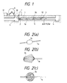
- Fig. 1 is an explanatory diagram showing an apparatus and for measuring the length of a conduit according to an embodiment of the present invention.
- reference numeral 1 represents a linear material such as a filamentary body constituted by a wire 1a with large-diameter members 1b attached thereto; 2, a driving device for pulling the filamentary body 1 into a conduit 3 while supporting the large-diameter members 1b of the filamentary body 1; 4, manholes; 5, a laid cable; 6, a drum on which the filamentary body is wound; 7, a compressor for feeding air into the conduit 3; 12, a downsized microphone; 17, a receiving device for amplifying and indicating a signal from the microphone 12; and a seal 30 provided on the inlet side of the conduit 3 for preventing the air from flowing backward.
- a linear material such as a filamentary body constituted by a wire 1a with large-diameter members 1b attached thereto; 2, a driving device for pulling the filamentary body 1 into a conduit 3 while supporting the large-diameter members 1b of the filamentary body 1; 4, manholes; 5, a laid cable; 6, a drum on which the filamentary body
- the conduit 3 is formed of a hard vinyl circular pipe which has an inner diameter of 83 mm and which is buried over a distance of 200 m between the manholes 4 at a depth of 1.2 m in the underground.
- a communication cable 5 with a polyethylene coating having an outer diameter of 40 mm is already laid as the laid cable 5 in the conduit 3. The case of measuring the length of this conduit according to the present invention will be described.
- the filamentary body 1 is constituted by the wire la having an outer diameter of 2 mm and the large-diameter members 1b attached to the wire 1a at intervals of 5 m.
- the wire 1a is constituted by two insulated conductors which are coated with foamed polyethylene to have an outer diameter of 2 mm, and the large-diameter members 1b is formed of polyethylene foamed by about 50% and shaped into an elongated circle, as shown in Fig. 2(a), which has a length of 40 mm and a diameter of 25 mm.
- the downsized microphone 12 is attached to the large-diameter member 1b provided on the forward end of the filamentary body 1.
- Each of the large-diameter members 1b is made to have such a size that the filamentary body 1 does not encroach between the conduit 3 and the laid cable 5, and to be light and elastic enough to float while vibrating with a stronger air stream given thereto. Therefore, the shape and size of the large-diameter members 1b are determined depending on the relationship between a conduit 3 and a laid cable 5.
- Fig. 2(b) one of the large-diameter members 1b is shown which is constituted by a combination of spring materials and attached to the forward end of a filamentary body 1.
- the large-diameter member 1b is constituted by polypropylene tapes which are knitted into a shape of a spherical cage.
- Fig. 4 is a sectional view showing an example of the case of insertion of a filamentary body 1 having a large-diameter member 1b attached thereto when there is a laid cable 5 in a conduit 3.
- a wire 1a encroaches in a space 38 to make it difficult to insert the filamentary body 1.
- Such a large-diameter member 1b cannot encroach in the space 38, and in case where the wire 1b falls into the space 38, it cannot encroach therein since the large-diameter member 1b advances while vibrating.
- Fig. 3 is a diagram for explaining the operation of the driving device 2 which advances the large-diameter member 1b in such a way that the large-diameter member 1b is inserted between support poles 2b attached to each roller 2a which is rotating.
- the length of a conduit 3 has been measured.
- air was fed into a conduit by the compressor 7 so as to insert a filamentary body 1 thereinto by means of the flow of the air.
- the large-diameter member 1b was supported and fed by the driving device 2 shown in Fig. 3 so that the filamentary body 1 was drawn out from the drum 6.
- air flow of 10 m/second was fed into the conduit 3 and the work was completed in 20 minutes after starting insertion of the filamentary body 1. It was possible to receive the sound of the air flow from the microphone on the forward end through the conductors in the wire la during the insertion, and it was also possible to confirm the arrival of the forward end at the outlet-side manhole 4 with the air flow weaken.
- the air flow was stopped to try to pull back the filamentary body 1, but the resistance was so large that the filamentary body 1 could not be moves even by application of tension of not smaller than 10 kg. Then, when the air flow of 10 m/second was fed thereto again, the filamentary body 1 could be pulled back with 7 kg at maximum in spite of the direction contrary to that of the air flow.
- Fig. 5 illustrates an apparatus for measuring the length of a conduit 3 according to another embodiment of the present invention.
- the same parts in description of the drawings are referenced correspondingly, and the description will not be repeated.
- reference numeral 1 represents a filamentary body made by fiber reinforced plastic having an outer diameter of 8 mm including a metal communication line; 12, a small microphone attached to the forward end of the filamentary body 1; 3, a conduit constituted by a hard vinyl circular pipe of inner diameter 75 mm; 4, manholes; 2, a caterpillar-type driving device for pushing the filamentary body 1 into the conduit 3; 6, a drum; and 17, a receiving device for amplifying and indicating a signal from the microphone 12 through the communication line.
- the conduit 3 is buried over a distance of 100 mm between the manholes 4 and 4 at a depth of 1 m under the ground.
- the filamentary body 1 having rigidity is drawn out from the drum 6 by the driving device 2, and pushed into the conduit 3. At this time, the filamentary body 1 is pushed while contacting with the inner wall of the conduit 3, so that a sound is generated. This sound is received by the microphone 12, and transmitted to the receiving device 17 through the built-in communication line.
- the forward end of the filamentary body 1 has arrived at the outlet-side manhole 4, the forward end portion thereof is out of contact with the inner wall of the conduit 3 so that the signal level is reduced to make it possible to confirm the insertion.
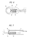
- Fig. 6 is a sectional view illustrating the configuration of a switch attached to the forward end of a filamentary body. The case of providing a switch 20 in place of the microphone 12 attached to the forward end of the filamentary body 1 in Fig. 1 will be described.
- a contact 21 is connected to one end of a metal communication line 1' built in the filamentary body 1, the other end of the communication line 1' being connected to a spring 23.
- the wind receiving portion 24 is pulled against the spring 23 by the air flow so that the contacts 21 and 22 are separated from each other as shown, and then the OFF state of the switch 20 is indicated as a result of observation by the receiving device 17 through the communication line 1'.
- the receiving device 17 indicates the OFF state of the switch 20, and thereafter the switch 20 will change from the OFF state to the ON state if the forward end of the filamentary body 1 arrives at an outlet-side manhole 4, so that it can be confirmed that the filamentary body 1 has been inserted.
- thermocouple employed as a sensor 12.
- a transponder for example, made by Texas Instruments Inc.
- Fig. 7 is an enlarged diagram illustrating the configuration of the inlet of a conduit according to the present invention.
- a seal 30 is provided on the inlet side of the conduit 3 in such a manner that air, which is fed into the conduit 3 by means of the compressor 7, is prevented from flowing backward.
- the filamentary body 1, which is drawn out from the drum 6, is fed into the conduit 3 through a guide pipe 22 which passes through the seal 30.
- the guide pipe 22 has an inner diameter of 36 mm and a length of 6 m, and is provided at the inlet of the conduit 3, and the length of the guide pipe 22 is selected such that when one of the large-diameter members 1b of the filamentary body 1 is fed from the guide pipe 22 into conduit 3, the next one large-diameter member 1b enters the inside of the guide pipe 22 so that there is no fear that the air flow leaks into the inlet-side manhole 4.
- Figs. 8(a) is a perspective view illustrating the structure of a guide pipe according to another embodiment of the present invention.
- openable/closable doors 22a and 22b are provided at a certain interval so that the door 22a is opened when one large-diameter member 1b of the filamentary body 1 passes therethrough and closed when the large-diameter member 1b has passed therethrough.
- the next door 22b is opened/closed in the same manner.
- Clasps 22c are provided so as to be capable of preventing the respective doors 22a and 22b from opening in the direction opposite to the passing direction of the filamentary body 1.
- the interval between the two doors 22a and 22b is selected to be different from the interval between the large-diameter members 1b so that either one of the two doors 22a and 22b is always closed to thereby prevent the air in the conduit 3 provided through a flange 28 from flowing backward.
- one of the doors 22a and 22b is provided so as to be movable in the longitudinal direction of the filamentary body 1.
- the above-mentioned doors 22a and 22b are shown merely by way of example, and the present invention is not limited to the shape, the number and so on of the illustrated doors.
- Fig. 8(b) is a perspective view illustrating the structure of another guide pipe, in which the doors 22a and 22b are replaced by shutters 22d and 22e.
- Each of the shutters 22d and 22e has a central aperture which is changed by opening/closing a plurality of plates 22f so that the aperture is opened when the large-diameter member 1b of the filamentary body 1 passes therethrough, while closed after the large-diameter member 1b has passed.
- a noncontacting switch is provided on each door or shutter, the filamentary body 1 can be inserted smoothly by controlling the door or shutter so that the door or shutter is opened when the large-diameter member 1b comes up thereto, and closed after the large-diameter member 1b has passed. Though the large-diameter member 1b of the filamentary body 1 cannot pass through the door or shutter when it is closed, the wire 1a of the filamentary body 1 can be inserted through a small hole.
- a total of force exerted on the large-diameter members 1b is proportional to the number of the large-diameter members 1b without any influence of pressure loss due to the existence of the large-diameter members 1b when the conduit 3 has a length of 500 m or less and an inner diameter of 60-120 mm, the diameter of the large-diameter members 1b is between 15 mm and 45 mm, and an interval between the adjacent large-diameter members 1b is 30 cm or more.
- an interval at which the large-diameter members 1b are disposed is made narrower, then the large forwarding force for the large-diameter members 1b can be obtained.
- an air blower put on the market air having a flow rate of 1000-3000 liter/minute can be utilized, thereby saving costs in equipment.
- an interval between the large-diameter members 1b is preferably selected to 30-500 cm under the above-mentioned conditions.
- the interval is set to 1 m or less, there can be obtained a forwarding force capable of allowing the filamentary body 1 to pass through the conduit 3 having a length of.100 m within 3 minutes.
- air is fed into a conduit to insert a filamentary body into the conduit by means of the flow of this air to thereby measure the length of the conduit.
- Light large-diameter members having predetermined size are attached to the filamentary body to thereby increase the force of propelling the filamentary body as well as give vibration to the filamentary body by disturbing the air, so that the filamentary body can be inserted smoothly without any problem such as encroaching of the wire even if any laid cables exist in the conduit.
- a sensor or an oscillation element is attached to the forward end of the filamentary body to detect a signal from the forward end, it is possible to surely insert the filamentary body into the conduit even if the conduit is narrow and long. With such a method to measure the conduit length, it is possible to manufacture cables having connectors attached to their opposite ends, and to lay the cables in the conduit.
- a sound produced when a filamentary body is pushed into a conduit while contacting with an inner wall of the conduit is detected through a microphone attached to the forward end of the filamentary body.
- a guide pipe is provided at the inlet of the conduit, in such a manner that the filamentary body is fed through the guide pipe so that the air flow is prevented from flowing backward and leaking out in the vicinity of the inlet, and further the filamentary body is fed into the conduit from the guide pipe in the place where the air flow is stable, so that the filamentary body can receive a stable propellant force.
Landscapes
- Physics & Mathematics (AREA)
- General Physics & Mathematics (AREA)
- Electric Cable Installation (AREA)
- Length Measuring Devices Characterised By Use Of Acoustic Means (AREA)
- Investigating Or Analyzing Materials By The Use Of Ultrasonic Waves (AREA)
Claims (24)
- Ein Verfahren zum Messen einer Länge einer Leitung mit den folgenden Schritten:Vorsehen eines fadenförmigen Körpers mit einem Draht (1a) und einer Vielzahl von elastischen Elementen (1b) großen Durchmessers, die an dem Draht angebracht sind;Zuführen von Luft in die Leitung (3) zur Einfügung des fadenförmigen Körpers (1) in die Leitung durch den Luftfluß;Detektieren der Ankunft eines vorderen Endes des fadenförmigen Körpers an einem Auslaß (4) der Leitung; undMessen der Länge der Leitung aus der Länge des in die Leitung eingefügten fadenförmigen Körpers.
- Ein Verfahren wie in Anspruch 1 beansprucht, wobei der Detektionsschritt ein Detektieren eines Geräusches des Luftflusses in der Leitung durch ein Mikrophon (12), das an dem vorderen Ende des fadenförmigen Körpers (1) angebracht ist, umfaßt.
- Ein Verfahren wie in Anspruch 1 beansprucht, wobei der Detektionsschritt ein Detektieren der Intensität des Luftflusses in der Leitung durch einen Schalter (20), der an dem vorderen Ende des fadenförmigen Körpers (1) angebracht ist, umfaßt.
- Ein Verfahren zum Messen einer Länge einer Leitung mit den folgenden Schritten: Vorsehen eines fadenförmigen Körpers mit einem Draht (1a) und einer Vielzahl von elastischen Elementen (1b) großen Durchmessers, die an dem Draht angebracht sind;Einfügen des fadenförmigen Körpers (1) in die Leitung (3) durch eine Treibvorrichtung (2);Detektieren eines durch Berührung des fadenförmigen Körpers mit einer inneren Wand der Leitung hervorgerufenen Geräuschs durch ein Mikrophon (12), das an einem vorderen Ende des fadenförmigen Körpers (1) angebracht ist;Detektieren der Ankunft eines vorderen Endes des fadenförmigen Körpers (1) an einem Auslaß (4) der Leitung durch Detektieren einer Änderung in dem erzeugten Geräusch; undMessen der Länge der Leitung aus der Länge des in die Leitung eingefügten fadenförmigen Körpers.
- Eine Vorrichtung zum Messen einer Länge einer Leitung mit:dadurch gekennzeichnet, daßeinem fadenförmigen Körper (1);,Mitteln (12, 17) zum Detektieren, daß ein vorderes Ende des fadenförmigen Körpers an einem Auslaßende der Leitung ankommt,wobei die Länge der Leitung aus der Länge des in die Leitung eingefügten fadenförmigen Körpers gemessen wird,weiter Luftzuführmittel (7) zum Zuführen von Luft in die Leitung (3) vorhanden sind; und daßder fadenförmige Körper einen Draht (1a) und eine Vielzahl von elastischen Elementen (1b) großen Durchmessers, die an dem Draht angebracht sind, enthält.
- Eine Vorrichtung gemäß Anspruch 5, wobei die Elemente (1b) großen Durchmessers an einem vorderen Ende und an mittleren Positionen des Drahts angebracht sind.
- Eine Vorrichtung gemäß Anspruch 5, wobei die Elemente (1b) großen Durchmessers an dem Draht unter vorbestimmten Abständen angebracht sind.
- Eine Vorrichtung gemäß Anspruch 5, wobei die Elemente (1b) großen Durchmessers in der Größe größer sind als ein Raum, der durch den Raum zwischen der Innenoberfläche der Leitung und einem darin bereits verlegten Kabel bestimmt ist.
- Eine Vorrichtung gemäß Anspruch 5, weiter mit einem Sensor (12), der in einem vorderen Ende des fadenförmigen Körpers angebracht ist.
- Eine Vorrichtung gemäß Anspruch 5, weiter mit einem Schwingungselement (20), das an dem vorderen Ende des fadenförmigen Körpers angebracht ist.
- Eine Vorrichtung gemäß Anspruch 5, weiter mit einem Führungsrohr (22), das an einem Einlaß der Leitung vorgesehen ist, durch das der fadenförmige Körper in die Leitung mittels des Luftflusses eingeführt wird.
- Eine Vorrichtung gemäß Anspruch 11, wobei das Führungsrohr (22) einen inneren Durchmesser aufweist, der im wesentlichen gleich ist zu einem äußeren Durchmesser der Elemente (1b) großen Durchmessers des fadenförmigen Körpers.
- Eine Vorrichtung gemäß Anspruch 11, wobei das Führungsrohr (22) eine Länge aufweist, die länger ist als der Abstand der Elemente (1b) großen Durchmessers, die an dem fadenförmigen Körper angebracht sind.
- Eine Vorrichtung gemäß Anspruch 11, wobei das Führungsrohr (22) darin wenigstens zwei aufmachbare/verschließbare Türen (22a, 22b) enthält, die unter einem Abstand vorgesehen sind.
- Eine Vorrichtung gemäß Anspruch 11, wobei das Führungsrohr (22) darin wenigstens zwei Verschlüsse (22d, 22e) enthält, die in einem Abstand vorgesehen sind.
- Eine Vorrichtung gemäß Anspruch 15, wobei der Verschluß eine Vielzahl von Platten (22f) enthält, die zentrale Öffnungen bestimmen, die in ihrem Durchmesser durch ÖffnenNerschließen der Vielzahl von Platten verändert werden.
- Eine Vorrichtung gemäß Anspruch 14, wobei die Türen (22a, 22b) des Führungsrohrs (22) so vorgesehen sind, daß sie sich nur in der Richtung der Einfügung des fadenförmigen Körpers öffnen.
- Eine Vorrichtung gemäß Anspruch 14, wobei ein Abstand zwischen den Türen (22a, 22b) sich von einem Abstand zwischen den Elementen (1b) großen Durchmessers, die nebeneinander liegen, unterscheidet.
- Eine Vorrichtung gemäß Anspruch 15, wobei der Abstand zwischen den Verschlüssen (22d, 22e) sich von einem Abstand zwischen den Elementen (1b) großen Durchmessers, die nebeneinander liegen, unterscheidet.
- Eine Vorrichtung gemäß Anspruch 14, wobei wenigstens eine der Türen (22a, 22b) in der Längsrichtung des fadenförmigen Körpers bewegbar ist.
- Eine Vorrichtung gemäß Anspruch 15, wobei wenigstens einer der Verschlüsse (22d, 22e) in der Längsrichtung des fadenförmigen Körpers bewegbar ist.
- Eine Vorrichtung gemäß Anspruch 14, wobei die Türen (22a, 22b) gemäß einer Zuführgeschwindigkeit der Elemente (1b) großen Durchmessers, die an dem fadenförmigen Körper angebracht sind, geöffnet/verschlossen werden.
- Eine Vorrichtung gemäß Anspruch 15, wobei die Verschlüsse (22d, 22e) gemäß einer Zuführgeschwindigkeit der Elemente (1b) großen Durchmessers, die an dem fadenförmigen Körper angebracht sind, geöffnet/geschlossen werden.
- Eine Vorrichtung gemäß Anspruch 14, wobei der innere Durchmesser des Führungsrohrs (22) im wesentlichen gleich ist zu dem äußeren Durchmesser der Elemente (1b) großen Durchmessers, die an dem fadenförmigen Körper angebracht sind, und nicht länger als der Abstand zwischen den Elementen großen Durchmessers.
Applications Claiming Priority (8)
| Application Number | Priority Date | Filing Date | Title |
|---|---|---|---|
| JP23674692A JPH0682201A (ja) | 1992-09-04 | 1992-09-04 | 管路長の測定方法 |
| JP236746/92 | 1992-09-04 | ||
| JP298533/92 | 1992-11-09 | ||
| JP29853392A JPH06147801A (ja) | 1992-11-09 | 1992-11-09 | 管路長の測定方法及び管路内の診断方法 |
| JP348119/92 | 1992-12-28 | ||
| JP34811992 | 1992-12-28 | ||
| JP130178/93 | 1993-06-01 | ||
| JP13017893A JPH06249601A (ja) | 1992-12-28 | 1993-06-01 | 管路長の測定方法及び装置 |
Publications (3)
| Publication Number | Publication Date |
|---|---|
| EP0585902A2 EP0585902A2 (de) | 1994-03-09 |
| EP0585902A3 EP0585902A3 (de) | 1994-12-07 |
| EP0585902B1 true EP0585902B1 (de) | 1998-08-05 |
Family
ID=27471512
Family Applications (1)
| Application Number | Title | Priority Date | Filing Date |
|---|---|---|---|
| EP93113983A Expired - Lifetime EP0585902B1 (de) | 1992-09-04 | 1993-09-01 | Verfahren und Apparat zur Messung der Länge von Leitungen |
Country Status (4)
| Country | Link |
|---|---|
| US (2) | US5505086A (de) |
| EP (1) | EP0585902B1 (de) |
| KR (1) | KR0133033B1 (de) |
| DE (1) | DE69320121D1 (de) |
Families Citing this family (7)
| Publication number | Priority date | Publication date | Assignee | Title |
|---|---|---|---|---|
| FR2729939B1 (fr) * | 1995-01-31 | 1997-04-18 | Neopost Ind | Dispositif d'assistance au reglage de dimensions de pliage dans une machine plieuse insereuse |
| KR100940766B1 (ko) * | 2005-07-21 | 2010-02-10 | 규슈덴료쿠 가부시키가이샤 | 관로 시험체 및 관로 시험 방법 |
| US7987611B2 (en) * | 2008-07-29 | 2011-08-02 | Curtis Patrick Taylor | Self-extending elongate member and use thereof |
| CN105318859B (zh) * | 2014-08-01 | 2019-06-25 | 上海凯盾工程技术有限公司 | 直接测量监控地下管线和建筑结构沉降变形方法及其装置 |
| US10704935B2 (en) * | 2016-12-04 | 2020-07-07 | Buoy Labs, Inc. | Fluid flow detector with tethered drag block |
| CN110220484B (zh) * | 2019-06-17 | 2022-02-18 | 西安科技大学 | 一种钻孔内壁超声波扫描成像装置及方法 |
| CN111780328B (zh) * | 2020-06-24 | 2021-12-14 | 珠海格力电器股份有限公司 | 一种送风控制方法、装置及空调设备 |
Family Cites Families (19)
| Publication number | Priority date | Publication date | Assignee | Title |
|---|---|---|---|---|
| US4014102A (en) * | 1975-08-21 | 1977-03-29 | Japan Metals And Chemicals Co., Ltd. | Method of and an apparatus for measuring the electrode length in an electric furnace |
| JPS58122404A (ja) * | 1982-01-14 | 1983-07-21 | Hitachi Cable Ltd | 核燃料被覆管内面の銅皮膜厚測定方法 |
| JPS5915808A (ja) * | 1982-03-03 | 1984-01-26 | Hitachi Ltd | グラフアイトコ−テイング燃料被覆管の被膜測定方法 |
| US4597183A (en) * | 1983-02-24 | 1986-07-01 | Standard Oil Company (Indiana) | Methods and apparatus for measuring a length of cable suspending a well logging tool in a borehole |
| US4541278A (en) * | 1984-04-23 | 1985-09-17 | Union Oil Company Of California | Pipeline corrosion sensing device and method |
| JPS61756A (ja) * | 1984-06-13 | 1986-01-06 | Mitsubishi Heavy Ind Ltd | 管の超音波探傷方法 |
| DE3542163C1 (de) * | 1985-11-26 | 1986-09-25 | Mannesmann AG, 4000 Düsseldorf | Verfahren zur UEberpruefung der Innengeometrie von Rohren |
| JPS63243750A (ja) * | 1987-03-31 | 1988-10-11 | Sekiyu Sangyo Katsuseika Center | 管内検査装置 |
| JPS6478184A (en) * | 1987-06-24 | 1989-03-23 | Nippon Kokan Kk | Method and device for deriving length of tubular body by utilizing acoustic wave |
| US4852262A (en) * | 1988-01-21 | 1989-08-01 | United States Of America, As Represented By The Secretary Of The Interior | Gauge for in situ measurement of borehole diameter |
| US4935884A (en) * | 1988-04-28 | 1990-06-19 | Champlin Electronics, Inc. | Sonic pipe length detector |
| US4866978A (en) * | 1988-08-17 | 1989-09-19 | Biggerstaff Bruce A | Pipe inspection method and device |
| US4930350A (en) * | 1988-10-06 | 1990-06-05 | Robert Bode | Acoustical length measurement |
| GB2230612A (en) * | 1989-04-13 | 1990-10-24 | Pearpoint Ltd | Cable/rod measuring system |
| FR2659437B1 (fr) * | 1990-03-07 | 1994-03-25 | Caoutchouc Manufacture Plastique | Moyen de reperage lineaire de longueur, de vitesse ou de positionnement pour article souple de grande longeur. |
| GB2242497B (en) * | 1990-03-31 | 1992-08-12 | Stc Plc | Pipe inspection system |
| JPH04169838A (ja) * | 1990-11-02 | 1992-06-17 | Furukawa Electric Co Ltd:The | 細径管路の障害検知方法 |
| JP2612982B2 (ja) * | 1991-11-05 | 1997-05-21 | 日本電信電話株式会社 | 鋼管柱の劣化診断方法 |
| US5205048A (en) * | 1991-11-20 | 1993-04-27 | Tdw Delaware, Inc. | Pipeline bend detector pig |
-
1993
- 1993-09-01 EP EP93113983A patent/EP0585902B1/de not_active Expired - Lifetime
- 1993-09-01 DE DE69320121T patent/DE69320121D1/de not_active Expired - Lifetime
- 1993-09-03 KR KR1019930017610A patent/KR0133033B1/ko not_active Expired - Fee Related
- 1993-09-03 US US08/115,686 patent/US5505086A/en not_active Expired - Fee Related
-
1994
- 1994-08-02 US US08/284,207 patent/US5528938A/en not_active Expired - Fee Related
Also Published As
| Publication number | Publication date |
|---|---|
| US5528938A (en) | 1996-06-25 |
| US5505086A (en) | 1996-04-09 |
| EP0585902A2 (de) | 1994-03-09 |
| DE69320121D1 (de) | 1998-09-10 |
| KR0133033B1 (ko) | 1998-04-20 |
| KR940008182A (ko) | 1994-04-29 |
| EP0585902A3 (de) | 1994-12-07 |
Similar Documents
| Publication | Publication Date | Title |
|---|---|---|
| EP2002298B1 (de) | Detektion der kabelverlegung | |
| US7331215B2 (en) | Deployment of equipment into fluid containers and conduits | |
| EP1494005A1 (de) | Verfahren und Vorrichtung zur Leckaufspürung | |
| EP0442626B1 (de) | Installieren von Kabeln in Schächten | |
| CA1179526A (en) | Method and apparatus to measure tension in a pull line for cable | |
| EP0585902B1 (de) | Verfahren und Apparat zur Messung der Länge von Leitungen | |
| JP2834702B2 (ja) | 検出装置 | |
| US9774175B2 (en) | Cable installation apparatus | |
| AU631015B2 (en) | Deploying cables | |
| AU608869B2 (en) | Duct testing | |
| US6005396A (en) | Method for inspecting the elements of piping systems by electromagnetic waves | |
| EP2075609A1 (de) | Erkennung einer Kabelinstallation über Luftfluss | |
| KR920002178B1 (ko) | 내면 코트(coat)한 금속관의 코트상태 검사방법 및 장치 | |
| JPH04240806A (ja) | 線材の布設方法 | |
| JPH028643B2 (de) | ||
| JPH062934U (ja) | 管路長計尺装置 | |
| JPH0735152A (ja) | 角度検出機能付球面継手および管路の曲率測定装置 | |
| JPH0682201A (ja) | 管路長の測定方法 | |
| KR0120128Y1 (ko) | 하수관 등의 텔레비젼 관로조사 시스템에서 케이블 감이장치의 케이블 | |
| JPH09229812A (ja) | ケーブルのガス漏洩位置探索方法 | |
| JPH0694403A (ja) | 管路長の測定方法 | |
| JP2001021435A (ja) | 水道管の漏水箇所検知方法及び漏水箇所の検知装置 | |
| JPH0682202A (ja) | 管路長の測定方法 | |
| JPH06147801A (ja) | 管路長の測定方法及び管路内の診断方法 | |
| JPH06222221A (ja) | 管路内の診断方法及び装置 |
Legal Events
| Date | Code | Title | Description |
|---|---|---|---|
| PUAI | Public reference made under article 153(3) epc to a published international application that has entered the european phase |
Free format text: ORIGINAL CODE: 0009012 |
|
| AK | Designated contracting states |
Kind code of ref document: A2 Designated state(s): DE DK ES FR GB IT SE |
|
| PUAL | Search report despatched |
Free format text: ORIGINAL CODE: 0009013 |
|
| AK | Designated contracting states |
Kind code of ref document: A3 Designated state(s): DE DK ES FR GB IT SE |
|
| 17P | Request for examination filed |
Effective date: 19950120 |
|
| 17Q | First examination report despatched |
Effective date: 19960425 |
|
| GRAG | Despatch of communication of intention to grant |
Free format text: ORIGINAL CODE: EPIDOS AGRA |
|
| GRAG | Despatch of communication of intention to grant |
Free format text: ORIGINAL CODE: EPIDOS AGRA |
|
| GRAH | Despatch of communication of intention to grant a patent |
Free format text: ORIGINAL CODE: EPIDOS IGRA |
|
| GRAH | Despatch of communication of intention to grant a patent |
Free format text: ORIGINAL CODE: EPIDOS IGRA |
|
| GRAA | (expected) grant |
Free format text: ORIGINAL CODE: 0009210 |
|
| AK | Designated contracting states |
Kind code of ref document: B1 Designated state(s): DE DK ES FR GB IT SE |
|
| PG25 | Lapsed in a contracting state [announced via postgrant information from national office to epo] |
Ref country code: IT Free format text: LAPSE BECAUSE OF FAILURE TO SUBMIT A TRANSLATION OF THE DESCRIPTION OR TO PAY THE FEE WITHIN THE PRE;WARNING: LAPSES OF ITALIAN PATENTS WITH EFFECTIVE DATE BEFORE 2007 MAY HAVE OCCURRED AT ANY TIME BEFORE 2007. THE CORRECT EFFECTIVE DATE MAY BE DIFFERENT FROM THE ONE RECORDED.SCRIBED TIME-LIMIT Effective date: 19980805 Ref country code: FR Free format text: LAPSE BECAUSE OF FAILURE TO SUBMIT A TRANSLATION OF THE DESCRIPTION OR TO PAY THE FEE WITHIN THE PRESCRIBED TIME-LIMIT Effective date: 19980805 Ref country code: ES Free format text: THE PATENT HAS BEEN ANNULLED BY A DECISION OF A NATIONAL AUTHORITY Effective date: 19980805 |
|
| REF | Corresponds to: |
Ref document number: 69320121 Country of ref document: DE Date of ref document: 19980910 |
|
| PG25 | Lapsed in a contracting state [announced via postgrant information from national office to epo] |
Ref country code: SE Free format text: LAPSE BECAUSE OF FAILURE TO SUBMIT A TRANSLATION OF THE DESCRIPTION OR TO PAY THE FEE WITHIN THE PRESCRIBED TIME-LIMIT Effective date: 19981105 Ref country code: DK Free format text: LAPSE BECAUSE OF FAILURE TO SUBMIT A TRANSLATION OF THE DESCRIPTION OR TO PAY THE FEE WITHIN THE PRESCRIBED TIME-LIMIT Effective date: 19981105 |
|
| PG25 | Lapsed in a contracting state [announced via postgrant information from national office to epo] |
Ref country code: DE Free format text: LAPSE BECAUSE OF FAILURE TO SUBMIT A TRANSLATION OF THE DESCRIPTION OR TO PAY THE FEE WITHIN THE PRESCRIBED TIME-LIMIT Effective date: 19981106 |
|
| EN | Fr: translation not filed | ||
| PLBE | No opposition filed within time limit |
Free format text: ORIGINAL CODE: 0009261 |
|
| 26N | No opposition filed | ||
| PGFP | Annual fee paid to national office [announced via postgrant information from national office to epo] |
Ref country code: GB Payment date: 19990901 Year of fee payment: 7 |
|
| PG25 | Lapsed in a contracting state [announced via postgrant information from national office to epo] |
Ref country code: GB Free format text: LAPSE BECAUSE OF NON-PAYMENT OF DUE FEES Effective date: 20000901 |
|
| GBPC | Gb: european patent ceased through non-payment of renewal fee |
Effective date: 20000901 |