EP2348182A2 - Porte, notamment porte à sections relevables - Google Patents
Porte, notamment porte à sections relevables Download PDFInfo
- Publication number
- EP2348182A2 EP2348182A2 EP11450004A EP11450004A EP2348182A2 EP 2348182 A2 EP2348182 A2 EP 2348182A2 EP 11450004 A EP11450004 A EP 11450004A EP 11450004 A EP11450004 A EP 11450004A EP 2348182 A2 EP2348182 A2 EP 2348182A2
- Authority
- EP
- European Patent Office
- Prior art keywords
- door
- sensors
- end strip
- strip
- drive device
- Prior art date
- Legal status (The legal status is an assumption and is not a legal conclusion. Google has not performed a legal analysis and makes no representation as to the accuracy of the status listed.)
- Withdrawn
Links
- 238000007789 sealing Methods 0.000 claims abstract description 9
- 229910052751 metal Inorganic materials 0.000 claims abstract description 6
- 239000002184 metal Substances 0.000 claims abstract description 6
- 238000004891 communication Methods 0.000 claims description 2
- 230000003287 optical effect Effects 0.000 abstract description 4
- 230000005540 biological transmission Effects 0.000 description 3
- 239000000758 substrate Substances 0.000 description 3
- 238000000034 method Methods 0.000 description 2
- 229910052782 aluminium Inorganic materials 0.000 description 1
- XAGFODPZIPBFFR-UHFFFAOYSA-N aluminium Chemical compound [Al] XAGFODPZIPBFFR-UHFFFAOYSA-N 0.000 description 1
- 230000033228 biological regulation Effects 0.000 description 1
- 230000008878 coupling Effects 0.000 description 1
- 238000010168 coupling process Methods 0.000 description 1
- 238000005859 coupling reaction Methods 0.000 description 1
- 238000001514 detection method Methods 0.000 description 1
- 238000010586 diagram Methods 0.000 description 1
- 230000000694 effects Effects 0.000 description 1
- 230000005672 electromagnetic field Effects 0.000 description 1
- 239000000463 material Substances 0.000 description 1
- 230000006641 stabilisation Effects 0.000 description 1
- 238000011105 stabilization Methods 0.000 description 1
Images


Classifications
-
- E—FIXED CONSTRUCTIONS
- E06—DOORS, WINDOWS, SHUTTERS, OR ROLLER BLINDS IN GENERAL; LADDERS
- E06B—FIXED OR MOVABLE CLOSURES FOR OPENINGS IN BUILDINGS, VEHICLES, FENCES OR LIKE ENCLOSURES IN GENERAL, e.g. DOORS, WINDOWS, BLINDS, GATES
- E06B9/00—Screening or protective devices for wall or similar openings, with or without operating or securing mechanisms; Closures of similar construction
- E06B9/56—Operating, guiding or securing devices or arrangements for roll-type closures; Spring drums; Tape drums; Counterweighting arrangements therefor
- E06B9/80—Safety measures against dropping or unauthorised opening; Braking or immobilising devices; Devices for limiting unrolling
- E06B9/82—Safety measures against dropping or unauthorised opening; Braking or immobilising devices; Devices for limiting unrolling automatic
- E06B9/88—Safety measures against dropping or unauthorised opening; Braking or immobilising devices; Devices for limiting unrolling automatic for limiting unrolling
-
- E—FIXED CONSTRUCTIONS
- E05—LOCKS; KEYS; WINDOW OR DOOR FITTINGS; SAFES
- E05F—DEVICES FOR MOVING WINGS INTO OPEN OR CLOSED POSITION; CHECKS FOR WINGS; WING FITTINGS NOT OTHERWISE PROVIDED FOR, CONCERNED WITH THE FUNCTIONING OF THE WING
- E05F15/00—Power-operated mechanisms for wings
- E05F15/40—Safety devices, e.g. detection of obstructions or end positions
- E05F15/42—Detection using safety edges
- E05F15/44—Detection using safety edges responsive to changes in electrical conductivity
-
- E—FIXED CONSTRUCTIONS
- E05—LOCKS; KEYS; WINDOW OR DOOR FITTINGS; SAFES
- E05Y—INDEXING SCHEME ASSOCIATED WITH SUBCLASSES E05D AND E05F, RELATING TO CONSTRUCTION ELEMENTS, ELECTRIC CONTROL, POWER SUPPLY, POWER SIGNAL OR TRANSMISSION, USER INTERFACES, MOUNTING OR COUPLING, DETAILS, ACCESSORIES, AUXILIARY OPERATIONS NOT OTHERWISE PROVIDED FOR, APPLICATION THEREOF
- E05Y2800/00—Details, accessories and auxiliary operations not otherwise provided for
- E05Y2800/71—Secondary wings, e.g. pass doors
-
- E—FIXED CONSTRUCTIONS
- E05—LOCKS; KEYS; WINDOW OR DOOR FITTINGS; SAFES
- E05Y—INDEXING SCHEME ASSOCIATED WITH SUBCLASSES E05D AND E05F, RELATING TO CONSTRUCTION ELEMENTS, ELECTRIC CONTROL, POWER SUPPLY, POWER SIGNAL OR TRANSMISSION, USER INTERFACES, MOUNTING OR COUPLING, DETAILS, ACCESSORIES, AUXILIARY OPERATIONS NOT OTHERWISE PROVIDED FOR, APPLICATION THEREOF
- E05Y2900/00—Application of doors, windows, wings or fittings thereof
-
- E—FIXED CONSTRUCTIONS
- E05—LOCKS; KEYS; WINDOW OR DOOR FITTINGS; SAFES
- E05Y—INDEXING SCHEME ASSOCIATED WITH SUBCLASSES E05D AND E05F, RELATING TO CONSTRUCTION ELEMENTS, ELECTRIC CONTROL, POWER SUPPLY, POWER SIGNAL OR TRANSMISSION, USER INTERFACES, MOUNTING OR COUPLING, DETAILS, ACCESSORIES, AUXILIARY OPERATIONS NOT OTHERWISE PROVIDED FOR, APPLICATION THEREOF
- E05Y2900/00—Application of doors, windows, wings or fittings thereof
- E05Y2900/10—Application of doors, windows, wings or fittings thereof for buildings or parts thereof
- E05Y2900/106—Application of doors, windows, wings or fittings thereof for buildings or parts thereof for garages
-
- E—FIXED CONSTRUCTIONS
- E06—DOORS, WINDOWS, SHUTTERS, OR ROLLER BLINDS IN GENERAL; LADDERS
- E06B—FIXED OR MOVABLE CLOSURES FOR OPENINGS IN BUILDINGS, VEHICLES, FENCES OR LIKE ENCLOSURES IN GENERAL, e.g. DOORS, WINDOWS, BLINDS, GATES
- E06B3/00—Window sashes, door leaves, or like elements for closing wall or like openings; Layout of fixed or moving closures, e.g. windows in wall or like openings; Features of rigidly-mounted outer frames relating to the mounting of wing frames
- E06B3/70—Door leaves
- E06B2003/7057—Door leaves with little passing through doors
-
- E—FIXED CONSTRUCTIONS
- E06—DOORS, WINDOWS, SHUTTERS, OR ROLLER BLINDS IN GENERAL; LADDERS
- E06B—FIXED OR MOVABLE CLOSURES FOR OPENINGS IN BUILDINGS, VEHICLES, FENCES OR LIKE ENCLOSURES IN GENERAL, e.g. DOORS, WINDOWS, BLINDS, GATES
- E06B9/00—Screening or protective devices for wall or similar openings, with or without operating or securing mechanisms; Closures of similar construction
- E06B9/56—Operating, guiding or securing devices or arrangements for roll-type closures; Spring drums; Tape drums; Counterweighting arrangements therefor
- E06B9/68—Operating devices or mechanisms, e.g. with electric drive
- E06B2009/6809—Control
- E06B2009/6818—Control using sensors
- E06B2009/6836—Control using sensors sensing obstacle
-
- E—FIXED CONSTRUCTIONS
- E06—DOORS, WINDOWS, SHUTTERS, OR ROLLER BLINDS IN GENERAL; LADDERS
- E06B—FIXED OR MOVABLE CLOSURES FOR OPENINGS IN BUILDINGS, VEHICLES, FENCES OR LIKE ENCLOSURES IN GENERAL, e.g. DOORS, WINDOWS, BLINDS, GATES
- E06B7/00—Special arrangements or measures in connection with doors or windows
- E06B7/16—Sealing arrangements on wings or parts co-operating with the wings
- E06B7/22—Sealing arrangements on wings or parts co-operating with the wings by means of elastic edgings, e.g. elastic rubber tubes; by means of resilient edgings, e.g. felt or plush strips, resilient metal strips
- E06B7/23—Plastic, sponge rubber, or like strips or tubes
- E06B7/2316—Plastic, sponge rubber, or like strips or tubes used as a seal between the floor and the wing
-
- E—FIXED CONSTRUCTIONS
- E06—DOORS, WINDOWS, SHUTTERS, OR ROLLER BLINDS IN GENERAL; LADDERS
- E06B—FIXED OR MOVABLE CLOSURES FOR OPENINGS IN BUILDINGS, VEHICLES, FENCES OR LIKE ENCLOSURES IN GENERAL, e.g. DOORS, WINDOWS, BLINDS, GATES
- E06B7/00—Special arrangements or measures in connection with doors or windows
- E06B7/28—Other arrangements on doors or windows, e.g. door-plates, windows adapted to carry plants, hooks for window cleaners
- E06B7/32—Serving doors; Passing-through doors ; Pet-doors
-
- E—FIXED CONSTRUCTIONS
- E06—DOORS, WINDOWS, SHUTTERS, OR ROLLER BLINDS IN GENERAL; LADDERS
- E06B—FIXED OR MOVABLE CLOSURES FOR OPENINGS IN BUILDINGS, VEHICLES, FENCES OR LIKE ENCLOSURES IN GENERAL, e.g. DOORS, WINDOWS, BLINDS, GATES
- E06B9/00—Screening or protective devices for wall or similar openings, with or without operating or securing mechanisms; Closures of similar construction
- E06B9/02—Shutters, movable grilles, or other safety closing devices, e.g. against burglary
- E06B9/08—Roll-type closures
- E06B9/11—Roller shutters
- E06B9/17—Parts or details of roller shutters, e.g. suspension devices, shutter boxes, wicket doors, ventilation openings
- E06B9/17046—Bottom bars
Definitions
- the invention relates to a gate, in particular overhead sectional door, with a plurality of mutually pivotable sections having door leaf and a pivotally mounted door with a drive device and at least one of the drive device associated sensor, a lower end strip is provided, which has two spaced longitudinal edges.
- the width of the lower end profile of the sectional door, which forms a threshold in the area of the wicket door, is relatively small, so that it is sufficient to provide a substantially centered on the Torblattunterseite contact strip over which detects any obstacle and then the drive device are stopped can. It is known to provide contact strips, which have a rubber profile, which at the same time has the function of a seal between the door leaf and the ground or floor in the closed position of the door.
- EP 1 580 393 A2 is a sectional door with a relatively wide end profile known, in which case a safety device is provided for detecting an obstacle, which is fastened by means of a complex coupling arrangement pivotally mounted on the door leaf.
- a safety edge assembly for a movable closure in particular an overhead garage door known.
- an assembly which has a centrally disposed electrically conductive mounting rail or a conductive rail member.
- the electrically conductive member is associated with a tubular member of easily deformable material which effects a seal between the floor and the leading edge of the door when the door is in a closed position. The detection of a present in the edge region of the final profile obstacle is not achieved reliably.
- the safety device has a single light sensor, in which a light beam emanating from a transmitter is deflected at a profile end face and fed to the receiver arranged on the same side as the transmitter. Even with this deflected light beam, however, an obstacle present in the edge region of the end profile can not be reliably detected.
- a switching element in particular a switching strip or switching mat, known, in which two mutually spaced carrier elements are provided, wherein the switching mat and / or the carrier elements are formed as an antenna for emitting an electromagnetic field.
- the aim of the present invention is therefore to provide a goal of the type mentioned, in which - regardless of the width of the end profile - is easily ensured that there is an obstacle in an edge region of the end profile.
- the end strip can also have a comparatively large width, while nevertheless ensuring that obstacles, in particular body parts which are provided only in the edge regions below the end strip, are detected by the sensors and - if an obstacle should be detected via one of the two sensors - the drive device is stopped.
- a contact strip is provided as a sensor, which has two received in an elastic profile metal wires.
- Such contact strips are basically, in particular from the automotive industry, known as anti-trap, wherein the metal wires are usually taken in a rubber profile, which has only a height of 5 mm in the attached state, which extends beyond the lower edge of the end profile.
- two optical sensors may be provided.
- a contact strip with a linear cavity in particular a hollow rubber profile, in which at one end a terminating element with an optical transmitter, preferably an infrared light emitting diode (IR LED), and at the other end with a closing element an optical receiver is provided.
- an optical transmitter preferably an infrared light emitting diode (IR LED)
- IR LED infrared light emitting diode
- a cost-effective and also weight-saving design of the end strip which also allows a simple way attachment of the sensors in the edge regions, is given if the end strip in cross-section substantially in the shape of an inverted U, wherein at the two cantilevered leg ends in each case a groove is provided for fastening in each case a sensor.
- the contact strips can be inserted in a simple manner in the preferably at least one undercut groove having the end strip, so that a positive fastening of the sensors is achieved on the end strip in a simple manner.
- the end strip has a groove having a mounting rail between the two longitudinal edges.
- the sealing element in particular a sealing lip, can be fastened in a simple manner by simply inserting it into the groove of the central fastening rail, which recess preferably has an undercut.
- the end strip including sensors attached thereto has a possibly low height.
- the end strip together with the sensors has a height of less than 40 mm, in particular substantially 36 mm. If the gate has a comparatively large width of, for example, more than 3 m and a comparatively high height, e.g.
- the end strip has a width between 80 and 200 mm, preferably 100 to 150 mm, in particular of substantially 120 mm.
- the sensors are connected to a radio transmitter which is set up for communication with a radio receiver associated with the drive device, a cable connection between the moving door leaf and a control permanently mounted in a region adjoining the door is not required.
- the radio transmitter is in this case equipped with a battery as an energy source, which are exchanged in time intervals, eg a year, in a simple manner can.
- a cable connection in particular in the manner of a spiral cable for data transmission, ie transmission of the state of the contact strip to the drive unit, may be provided.
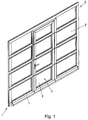
- Fig. 1 is a sectional door 1 can be seen, in which a door leaf 2 is divided into a plurality of mutually pivotally arranged sections 2 ', and in which a pivotally mounted wicket door 3 is added, wherein the door door leaf is also divided into sections 3'.
- a drive device 4 see. FIGS. 5 and 6
- a drive shaft (not shown) is driven, so that the sections 2 'of the door leaf 2 of the in Fig. 1 shown closed position can be converted into an open position in which the sections 2 'are arranged substantially horizontally.
- a capping bar 7 is attached, which is provided in particular in order to increase the stability of the door leaf 2 in the area of the slip door 3.
- the end bar 7 is in the FIGS. 2 to 4 shown in detail. It can be seen that the end strip 7 substantially has a U-shaped profile 8, which preferably consists of aluminum. As a result, the required strength is ensured, especially for large sectional doors, which have a width of more than 3 m and a height of more than 3 m.
- the end strip has a comparatively large width b of preferably 120 mm and a comparatively small height h of preferably 36 mm.
- the height h is in this case the distance from a provided in the region of the door 2 substrate to the highest projecting beyond the substrate extension of the end strip 7 (including provided as sensors 9 contact strips 10).
- the U-shaped profile 8 at the end portions of the cantilevered legs each have an undercut groove 11 in which a form-fitting contact strip 10 is added.
- Such contact strips 10 are well known in particular from the automotive industry, in which case usually a rubber profile is provided, in which two parallel metal wires 15 (see FIG. FIGS. 5 and 6 ) are poured.
- Such contact strips may have a relatively small height 1 of approximately 5 mm, which projects beyond the groove 11, so that the total height h of the end strip including the contact strips 10 is not substantially increased thereby.
- a fastening rail 12 is provided substantially centrally, which also has an undercut groove 13 at its free end, so that in this groove 13 in a simple manner an elastic sealing lip fourteenth can be recorded positively; with help the sealing lip 14 is in the in Fig. 1 shown closed position of the sectional door 1 ensures a tight seal.
- each contact strip 10 has two wires 15, which are arranged spaced apart in the unloaded state. Between the wires 15, a terminating resistor 16 is provided, which is preferably an 8k 2 resistor. If the contact strips 10 are therefore not elastically deformed, ie no force acts on them, a comparatively weak, defined current flows through the contact strips 10 and the terminating resistor 16, which is evaluated by the controller 4 'of the drive device 4.
- the arranged along the two longitudinal edges 7 'contact strips 10 are electrically connected in parallel via a connection 17, so that if one of the two contact strips 10 an obstacle is detected, due to a contact between the two wires 15, the terminator 16 is short-circuited and the current in the circuit for control 4 'of the drive device 4 consequently rises abruptly (if no current flows, however, a cable break is detected).
- the circuit for control 4 'via a cable, in particular a spiral cable 18 is closed; at the in Fig. 6 shown embodiment, however, a radio system is provided.
- the contact strips 10 also equipped with a battery radio transmitter 19 are actuated, the signal from a radio receiver 19 'received which is associated with the controller 4 'of the drive device 4. Regardless of the type of information transmission, the drive device 4 is thus stopped in an electrical contact between the metal wires 15 of the contact strip 10.
- the controller 4 ' is assigned a wicket door switch 20 via another cable 18 or the radio system 19, 19', so that the drive device 4 can only be activated if the wicket door switch 20 is closed.
Landscapes
- Engineering & Computer Science (AREA)
- Structural Engineering (AREA)
- Architecture (AREA)
- Civil Engineering (AREA)
- Power-Operated Mechanisms For Wings (AREA)
Applications Claiming Priority (1)
| Application Number | Priority Date | Filing Date | Title |
|---|---|---|---|
| AT0003010U AT11699U1 (de) | 2010-01-18 | 2010-01-18 | Tor, insbesondere deckensektionaltor |
Publications (2)
| Publication Number | Publication Date |
|---|---|
| EP2348182A2 true EP2348182A2 (fr) | 2011-07-27 |
| EP2348182A3 EP2348182A3 (fr) | 2014-03-26 |
Family
ID=43426191
Family Applications (1)
| Application Number | Title | Priority Date | Filing Date |
|---|---|---|---|
| EP11450004.4A Withdrawn EP2348182A3 (fr) | 2010-01-18 | 2011-01-18 | Porte, notamment porte à sections relevables |
Country Status (2)
| Country | Link |
|---|---|
| EP (1) | EP2348182A3 (fr) |
| AT (1) | AT11699U1 (fr) |
Cited By (1)
| Publication number | Priority date | Publication date | Assignee | Title |
|---|---|---|---|---|
| EP3674509B1 (fr) * | 2018-12-20 | 2026-04-22 | Alpha Deuren International BV | Élément de fermeture |
Families Citing this family (1)
| Publication number | Priority date | Publication date | Assignee | Title |
|---|---|---|---|---|
| DE102012015896A1 (de) * | 2012-08-10 | 2014-02-13 | Hörmann KG Brockhagen | Tor |
Citations (4)
| Publication number | Priority date | Publication date | Assignee | Title |
|---|---|---|---|---|
| DE4424510A1 (de) | 1993-07-19 | 1995-01-26 | Drumetra Inc | Sicherheits-Kanten-Baugruppe für einen beweglichen Verschluß |
| DE9418885U1 (de) | 1994-11-24 | 1996-03-28 | MARANTEC Antriebs- und Steuerungstechnik GmbH & Co. Produktions-KG, 33428 Marienfeld | Sicherungseinrichtung für die Schließkante eines angetriebenen Durchfahrtverschlusses |
| DE202004010395U1 (de) | 2004-07-01 | 2004-08-26 | Bircher Reglomat Ag | Schaltelement, insbesondere Schaltleiste oder Schaltmatte |
| EP1580393A2 (fr) | 2004-03-23 | 2005-09-28 | Hörmann KG Brockhagen | Porte |
Family Cites Families (1)
| Publication number | Priority date | Publication date | Assignee | Title |
|---|---|---|---|---|
| DE3232365C2 (de) * | 1982-08-31 | 1986-07-10 | Erwin Sick Gmbh Optik-Elektronik, 7808 Waldkirch | Elastisches Profil an der Schließkante einer Abdeckung |
-
2010
- 2010-01-18 AT AT0003010U patent/AT11699U1/de not_active IP Right Cessation
-
2011
- 2011-01-18 EP EP11450004.4A patent/EP2348182A3/fr not_active Withdrawn
Patent Citations (4)
| Publication number | Priority date | Publication date | Assignee | Title |
|---|---|---|---|---|
| DE4424510A1 (de) | 1993-07-19 | 1995-01-26 | Drumetra Inc | Sicherheits-Kanten-Baugruppe für einen beweglichen Verschluß |
| DE9418885U1 (de) | 1994-11-24 | 1996-03-28 | MARANTEC Antriebs- und Steuerungstechnik GmbH & Co. Produktions-KG, 33428 Marienfeld | Sicherungseinrichtung für die Schließkante eines angetriebenen Durchfahrtverschlusses |
| EP1580393A2 (fr) | 2004-03-23 | 2005-09-28 | Hörmann KG Brockhagen | Porte |
| DE202004010395U1 (de) | 2004-07-01 | 2004-08-26 | Bircher Reglomat Ag | Schaltelement, insbesondere Schaltleiste oder Schaltmatte |
Cited By (1)
| Publication number | Priority date | Publication date | Assignee | Title |
|---|---|---|---|---|
| EP3674509B1 (fr) * | 2018-12-20 | 2026-04-22 | Alpha Deuren International BV | Élément de fermeture |
Also Published As
| Publication number | Publication date |
|---|---|
| EP2348182A3 (fr) | 2014-03-26 |
| AT11699U1 (de) | 2011-03-15 |
Similar Documents
| Publication | Publication Date | Title |
|---|---|---|
| DE10141859B4 (de) | Verfahren und System zum Detektieren der Position eines angetriebenen Fensters eines Fahrzeugs | |
| AT412394B (de) | Schiebetritt | |
| EP2295700B1 (fr) | Porte | |
| DE4214998A1 (de) | Torantrieb und Verfahren zum Betreiben eines Torantriebes | |
| EP2880234A1 (fr) | Dispositif de surveillance et de commande pour une unité porte | |
| EP2236732B1 (fr) | Porte | |
| DE202006003313U1 (de) | Lichtschrankengehäuse, Lichtschrankenelement und Torvorrichtungen | |
| EP2348182A2 (fr) | Porte, notamment porte à sections relevables | |
| DE102011051336B3 (de) | Antriebseinrichtung | |
| DE202011101825U1 (de) | Schutzeinrichtung für ein Tor | |
| WO2015128387A1 (fr) | Ensemble de commutation de sécurité sur un appareil mobile, et procédé de production d'un dispositif de commutation de ce type | |
| EP3361029A1 (fr) | Dispositif d'entraînement pour un battant de porte ou de fenêtre | |
| EP2354415B1 (fr) | Porte sectionnelle | |
| EP0182019B1 (fr) | Bande protectrice contre les accidents | |
| EP1816264A1 (fr) | Barrière de sécurité et système de sécurité routière | |
| DE202017102443U1 (de) | Garagen-, Industrie- oder Einfahrtstor mit berührungsloser Schließkantensicherung | |
| DE29710499U1 (de) | Sicherheitsvorrichtung für verschiebbare Fensterscheiben | |
| DE202006020317U1 (de) | Motorisch angetriebenes Tor sowie Torantriebsvorrichtung und Kommunikationseinrichtung hierfür | |
| EP0713949A1 (fr) | Système de sécurité pour la bordure d'une fermeture motorisée d'un passage | |
| DE102004053820B4 (de) | Sensoranordnung für automatische Türanlagen | |
| WO2014040583A1 (fr) | Dispositif de fermeture avec sécurité de passage | |
| DE202010007949U1 (de) | Rolltor | |
| DE112005002388B4 (de) | Schutzschalteranordnung in einer Anzeigeanordnung eines Hefters mit elektrischem Antrieb | |
| DE202004010395U1 (de) | Schaltelement, insbesondere Schaltleiste oder Schaltmatte | |
| DE20311188U1 (de) | Sicherheitsleiste |
Legal Events
| Date | Code | Title | Description |
|---|---|---|---|
| PUAI | Public reference made under article 153(3) epc to a published international application that has entered the european phase |
Free format text: ORIGINAL CODE: 0009012 |
|
| AK | Designated contracting states |
Kind code of ref document: A2 Designated state(s): AL AT BE BG CH CY CZ DE DK EE ES FI FR GB GR HR HU IE IS IT LI LT LU LV MC MK MT NL NO PL PT RO RS SE SI SK SM TR |
|
| APBK | Appeal reference recorded |
Free format text: ORIGINAL CODE: EPIDOSNREFNE |
|
| APBN | Date of receipt of notice of appeal recorded |
Free format text: ORIGINAL CODE: EPIDOSNNOA2E |
|
| APBR | Date of receipt of statement of grounds of appeal recorded |
Free format text: ORIGINAL CODE: EPIDOSNNOA3E |
|
| APBV | Interlocutory revision of appeal recorded |
Free format text: ORIGINAL CODE: EPIDOSNIRAPE |
|
| RIN1 | Information on inventor provided before grant (corrected) |
Inventor name: KEROE, NIKOLAUS |
|
| PUAL | Search report despatched |
Free format text: ORIGINAL CODE: 0009013 |
|
| AK | Designated contracting states |
Kind code of ref document: A3 Designated state(s): AL AT BE BG CH CY CZ DE DK EE ES FI FR GB GR HR HU IE IS IT LI LT LU LV MC MK MT NL NO PL PT RO RS SE SI SK SM TR |
|
| RIC1 | Information provided on ipc code assigned before grant |
Ipc: E05F 15/00 20060101AFI20140214BHEP |
|
| 17P | Request for examination filed |
Effective date: 20140926 |
|
| RBV | Designated contracting states (corrected) |
Designated state(s): AL AT BE BG CH CY CZ DE DK EE ES FI FR GB GR HR HU IE IS IT LI LT LU LV MC MK MT NL NO PL PT RO RS SE SI SK SM TR |
|
| STAA | Information on the status of an ep patent application or granted ep patent |
Free format text: STATUS: THE APPLICATION IS DEEMED TO BE WITHDRAWN |
|
| 18D | Application deemed to be withdrawn |
Effective date: 20140927 |