EP2348184A2 - Gebäudeabschlusselement mit Verglasung sowie Herstellverfahren - Google Patents
Gebäudeabschlusselement mit Verglasung sowie Herstellverfahren Download PDFInfo
- Publication number
- EP2348184A2 EP2348184A2 EP11150036A EP11150036A EP2348184A2 EP 2348184 A2 EP2348184 A2 EP 2348184A2 EP 11150036 A EP11150036 A EP 11150036A EP 11150036 A EP11150036 A EP 11150036A EP 2348184 A2 EP2348184 A2 EP 2348184A2
- Authority
- EP
- European Patent Office
- Prior art keywords
- arrangement
- glazing
- frame
- building closure
- closure element
- Prior art date
- Legal status (The legal status is an assumption and is not a legal conclusion. Google has not performed a legal analysis and makes no representation as to the accuracy of the status listed.)
- Granted
Links
Images


Classifications
-
- E—FIXED CONSTRUCTIONS
- E06—DOORS, WINDOWS, SHUTTERS, OR ROLLER BLINDS IN GENERAL; LADDERS
- E06B—FIXED OR MOVABLE CLOSURES FOR OPENINGS IN BUILDINGS, VEHICLES, FENCES OR LIKE ENCLOSURES IN GENERAL, e.g. DOORS, WINDOWS, BLINDS, GATES
- E06B3/00—Window sashes, door leaves, or like elements for closing wall or like openings; Layout of fixed or moving closures, e.g. windows in wall or like openings; Features of rigidly-mounted outer frames relating to the mounting of wing frames
- E06B3/54—Fixing of glass panes or like plates
- E06B3/58—Fixing of glass panes or like plates by means of borders, cleats, or the like
- E06B3/5892—Fixing of window panes in openings in door leaves
Definitions
- the invention relates to a building closure element, in particular fire protection closure element, more particularly fire protection door leaf, with a particular flush-mounted glazing and a manufacturing method thereof.
- EP 1 586 734 A2 An example of a building closure element with flush glazing in fire protection training is in EP 1 586 734 A2 disclosed.
- the EP 1 586 734 A2 describes a fire door with a frame assembly in the form of a frame construction and a disc assembly, which is used in this frame construction.
- the pane arrangement has substantially the same thickness as the frame construction, so that a flush-mounted glazing is created.
- the disk assembly is formed of a plurality of glass sheets with spacers therebetween.
- the outer edges thereof are surrounded by thin edge strips of retaining plates. As a result, the glass panes between the spacer and the edge strips are added.
- the entire construction is suitable for fire protection, ie it can withstand relevant standards of one-sided exposure to fire for a minimum period of time.
- a flush-mounted glazing can also be created for a fire protection building closure element by this construction, so there is still an attached element due to the encompassing edge strips.
- the support structure is relatively complicated to manufacture and assembly.
- the object of the invention is to provide a building closure element with glazing, with a flush-mounted glazing can also be achieved in fire protection training with ease of manufacture and easy installation.
- the invention provides a building closure element, in particular fire protection closure element, in particular with flush-mounted glazing, comprising a frame arrangement and a pane arrangement to be used in the frame arrangement, characterized by a latching device for fastening the pane arrangement in the frame arrangement.
- the latching device is completely accommodated between at least one outer peripheral end face of the pane arrangement and one of these facing reveal side of a glazing opening in the frame arrangement.
- a latching device can be achieved on the one hand a simple attachment and a very simple installation of the disc assembly.
- a locking device is easy to manufacture and easy to install.
- the latching device can be completely concealed in the front side area between disc assembly and internal reveal accommodate. As a result, encompassing retaining strips are dispensable. It can create a complete flush glazing, this type of glazing is basically suitable for fire protection structures.
- the latching device has a stop for limiting the latching movement after successful latching.
- the latching means preferably includes a first member to be secured to the disc assembly and a second member to be secured to the frame assembly.
- One of the two elements is preferably a latching element with an elastically movable, biased in an engagement position engaging element.
- the other element of the latching device is preferably an abutment element for the latching element.
- the counter-bearing element preferably has a detection element, so that the engagement element can engage in the detection element in a form-fitting manner and lock there.
- stop areas of the stop are formed on the latching element and the counter-bearing element.
- the locking device is formed by a total of only two elements, so that it is easy to attach to the arrangements.
- a particularly simple and also suitable for fire protection construction is achieved when the elements of the latching device made of metal, in particular steel, and more particularly made of metal sheets, are made.
- at least one of these metal sheets, which form elements of the latching device is bent several times. By projecting bends of the metal sheets, for example, the stop areas can be formed.
- the engaging z. B. form by a bent sheet metal tongue.
- the detection element can be formed for example by a stepped deflection of one of the metal sheets.
- the disc assembly and the frame assembly are attached only to one side of a glazing border of the latching device.
- the disc assembly and the frame assembly on the opposite side z. B. be designed interlocking by a projection-recess formation. Then Initially, the engagement could be made on this projection-return formation and pivoted to the disc assembly, so as to engage the latching device.
- a pivotal assembly to be made is difficult because of the possible tilting between the disc assembly and the frame assembly. It is therefore provided according to a particularly preferred embodiment that the latching device is provided on a plurality, in particular on opposite sides of a glazing border. This allows the disc assembly to be displaced approximately perpendicular to the aperture plane relative to the frame assembly until the detents engage.
- At least one of the elements of the locking device is designed as a frame or in a frame.
- This may be, for example, a glazing profile frame surrounding the disk assembly and connected to the disk assembly.
- one or more locking tongues may be formed so that at least one locking device is provided on each of the outer end face; Preferably, several locking devices are present on each of the end faces.
- the second element of the latching device may be formed on a soffit profile frame, which is provided circumferentially in the inner soffit area of a glazing opening.
- the arranged on the disc assembly first element of the latching device is preferably attached to the associated end face of the disc assembly. This can be done by any suitable type of attachment, in particular pouring into the disc assembly, bonding with the disc assembly or by positive engagement, for example in the manner of a tongue and groove connection.
- An attachment of the second, to be arranged on the frame assembly element of the locking device can be done by any suitable means.
- this element is secured to the frame assembly by a plurality of screw fasteners or the like.
- the invention is particularly suitable for creating flush glazing, also in fire protection constructions.
- the invention is not limited to this application.
- the building closure element is designed as a door leaf.
- the door leaf is formed in fire protection construction as a door leaf of a fire door.
- the frame assembly is a door leaf frame or door leaf element with glazing cutout. In a glazing opening of the door leaf frame or the glazing cutout of the door leaf element, the pane arrangement can then be fastened in a latching manner by means of the latching device.
- a particularly economical method of manufacturing door leaf elements in fire protection structures is the so-called box-lid construction, in which a metal sheet - usually sheet steel - is formed as a kind of box, which is closed by a second metal sheet in the form of a lid. Insulation inserts, which ensure good fire protection, are then inserted in the interior of the cavity thus formed.
- box-lid construction in which a metal sheet - usually sheet steel - is formed as a kind of box, which is closed by a second metal sheet in the form of a lid. Insulation inserts, which ensure good fire protection, are then inserted in the interior of the cavity thus formed.
- the inventive attachment between the disc assembly and frame assembly by means of a locking device.
- the latching device can be formed and secured inside the reveal device and thus relatively protected and independent of the attachment of the outer sheet metal layers.
- the use of the locking device for fixing the disc assembly is therefore particularly preferred in constructions with a large-area bonding between metal sheets and insulation insert.
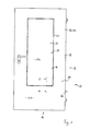
- a building closure element 10 is shown in the form of a door leaf 12 for a fire door 14 with flush glazing 15.
- the door leaf 12 has a frame assembly 16 with a glazing opening 18 into which a pane assembly 20 in fire protection formation is used to form the glazing 15.
- a detent 22 is provided that is received entirely within a glazing joint 24 between a peripheral face 26 of the disc assembly 20 and an inner reveal side 28 of the frame assembly 16.
- the disc assembly 20 and the frame assembly 16 have substantially the same thickness so that the outer sides 20a, 20b of the disc assembly 20 are substantially flush with the outer sides 16a, 16b of the frame assembly.
- the frame assembly 16 is designed as a door leaf frame construction 30 in fire protection training.
- the frame assembly 16 has for this purpose a first metal sheet in the form of a box plate 32 made of steel and a second metal sheet in the form of a cover plate 34 made of steel and an insulating insert 36 between the two metal sheets 32, 34.
- the insulating insert is glued to the box panel 32 and the cover plate 34 by means of a 1-K PU adhesive 38 over the entire surface. In other, not further illustrated embodiments, other adhesives are used for bonding.
- Insulating insert 36 has insulating strips 40 in the edge region surrounding glazing opening 18, for example materials comprising calcium silicates. In the region of the insulating strips 40 is a support means 42, on which the fastening of the glazing takes place.
- the carrier device 42 is in the in Fig. 2 illustrated embodiment formed by a T-profile 43, which is formed here simply by a multi-folded metal sheet. As a result, a T-shaped strip is formed, which passes continuously through the reveal side 28 and is welded to lateral (not shown) reinforcing profiles.
- the latching device 22 has a first element 44 fastened to the disk arrangement 20 and a second element 46 fastened to the frame arrangement 16.
- the two elements 44, 46 are locked together by a latching movement transversely to the opening plane of the glazing opening 18 with each other.
- the latching device 22 has a stop 52 formed between stop areas 48, 50 on the elements 44, 46 of the latching device 22 for limiting the latching movement.
- the first element 44 is connected to the disc assembly 20 and is disposed on the peripheral end face 26 thereof.
- the disk assembly 20 is formed of a plurality of individual glass sheets 54 which are interconnected. The same bonding technique for bonding the glass sheets 54 may be used to secure the first member 44 to the disk assembly 20.
- Conceivable are a casting with the disc assembly 20 or a gluing or the like.
- the first element 44 has a plurality of projections which positively engage the complementary joints in the disk arrangement 20 so as to hold the first element 44 to the disk arrangement.
- the first element 44 is part of a glazing profile frame 56 which surrounds the entire circumference of the pane arrangement 20 and is located in Fig. 11 is shown in more detail. How out Fig. 11 it can be seen, a plurality of locking devices 22 are provided per end side, so that the disc assembly 20 can be attached to each of the four peripheral end faces 26 with at least two locking devices 22.
- the second element 46 is also preferably arranged on a frame, which is present circumferentially within the reveal of the glazing opening 18 and is referred to below as a soffit profile frame 58.
- each support means 42 is provided on each reveal page 28 and each forms a frame member of the soffit profile frame 58th
- An each of these carriers 42 are as best as possible Fig. 11 can be seen, at least two second elements 46 for forming the plurality of locking devices 22 are provided.
- Each second element 46 is screwed by a plurality fferbefestiger 60, here in the form of tapping screws to the support means 42.
- the first element 44 is designed as a latching element 62 which has an elastically biased engagement element 64.
- the second element 46 is designed as an abutment element 66 with a sensing element 68 which engages the engagement element 64 in a latching manner.
- latching element 62 The more detailed structure of the latching element 62 will be described below with reference to the illustrations in FIGS Fig. 3 to 6 explained in more detail.
- the latching element 62 forming the first element 44 is formed from a multiply bent metal sheet 70, in particular sheet steel, and has an unlatched and bent sheet metal tongue 72 as the engagement element 64.
- the sheet tongue 72 is surrounded by a flat plate portion 73 of the metal sheet 70. Subsequently, the plate area 73, the metal plate 70 is projecting bent up on the same side as the tongue plate 72 so that a step edge 74 is formed, which forms the stop portion 48 of the first element 44.
- the metal tongue 72 is bent out in such an aligned manner that a free end thereof is directed towards the step flank 74.
- On the side facing away from the metal tongue 72 side of the step edge 74 connects to the step edge 74 a run-on slope 76, which opens into a flush with the plate portion 73 parallel edge strip 78.
- the construction of the second element 46 will be described below with reference to the illustrations in FIGS Fig. 7 to 10 explained in more detail.
- the abutment element 66 which forms the second element 46, is formed by a metal sheet 80, which is likewise bent several times and which is provided with a crank 84 for forming a step 82.
- a step flank 88 formed by the offset 84 serves as a detection element 68, which can be engaged behind by the sheet metal tongue 72.
- a adjoining the crank 84 first edge region 90 is provided with openings 92 for Recording the sortedbefestiger 60 provided.
- the openings 92 are elongated, so as to make a position adjustment of the second element 46 can.
- a second edge region 94 adjoining the offset 84 on the other side protrudes projectingly into the glazing opening 18 in the intended use and becomes visible in the in Fig. 2 shown locking state between the metal tongue 72 and the stepped edge 74 added.
- the free edge 96 of the second edge region 94 forms the stop region 50 of the second element 46 of the latching device 22.
- the procedure is such that the glazing opening 18 is cut out of a full-surface door leaf in a box-lid construction.
- the soffit area is then provided with the insulating strip 40.
- the support means 42 is welded with the reinforcing profiles and reinforcement beams in the glazing opening in the soffit area.
- the second element 46 is screwed to the support profile 42 with the screw fasteners 60. This results in the door leaf frame construction 100 with the glazing opening 18 and a plurality of second elements 46, as shown in FIG Fig. 11 is shown.
- the disk arrangement 20 is supplied, for example, with the first elements 44 fastened in the manufacturing plant for the disk arrangement 20.
- Fig. 11 For this purpose, only the glazing profile frame 56 accommodating the pane arrangement 20 with the first elements 44 formed integrally thereon is shown without the glass panes 54.
- the disc assembly 20 of the illustrated mounting direction 102 is inserted perpendicular to the aperture plane into the glazing port 18 until the tab 72 slides over the protrusion formed by the second edge portion 94 and snaps behind the step flank 88, wherein the edge 96 abuts the step flank 74 of the first element 44.
- the glazing joints 24 may be provided with strips of intumescent material as needed. These strips of intumescent material (not shown) may be previously, in particular in a groove in a region between the T-profile 43 and the box plate 32 or the cover plate 34 may be provided. The remaining area of the glazing joint 24 is potted from both sides with a sealing material (not shown) such as silicone.
- Fig. 12 is still a modified Au arrangementsform a glazed fire door panel 12 in a representation similar to the representation in Fig. 2 shown.
- This embodiment corresponds to the formation of the support means 42 of the previously with reference to the Fig. 2 illustrated embodiment.
- Corresponding parts are provided with corresponding reference numerals.
- the support means 42 has two angle sections 104 and 106.
- a first angle section 104 is fixed with a leg 104 a to the box panel 32 and a second angle section 106 is attached to a leg 106 a on the cover plate 34.
- the remaining legs 104b, 106b of the two angle sections 104, 106 overlap one another and thus reinforce the reveal area of the glazing opening 18.
- an insulation strip 108 made of fire protection material is inserted; including several layers of insulating strips 40 are provided.
- the screw fasteners 60 pass through both overlapping legs 104b, 106b. Otherwise, the structure of the second embodiment is the same as that of the first embodiment.
Landscapes
- Engineering & Computer Science (AREA)
- Civil Engineering (AREA)
- Structural Engineering (AREA)
- Special Wing (AREA)
- Securing Of Glass Panes Or The Like (AREA)
Abstract
Description
- Die Erfindung betrifft ein Gebäudeabschlusselement, insbesondere Brandschutzabschlusselement, mehr insbesondere Feuerschutz-Türblatt, mit einer insbesondere flächenbündigen Verglasung sowie ein Herstellverfahren hierfür.
- Ein Beispiel für ein Gebäudeabschlusselement mit flächenbündiger Verglasung in Brandschutzausbildung ist in der
EP 1 586 734 A2 offenbart. DieEP 1 586 734 A2 beschreibt ein Feuerschutz-Türblatt mit einer Rahmenanordnung in Form einer Rahmenkonstruktion und einer Scheibenanordnung, die in dieser Rahmenkonstruktion eingesetzt wird. Die Scheibenanordnung hat im Wesentlichen die gleiche Dicke wie die Rahmenkonstruktion, so dass eine flächenbündige Verglasung entsteht. Hierzu ist die Scheibenanordnung aus mehreren Glasscheiben mit Abstandshalter dazwischen ausgebildet. Zum Halten der mehreren Glasscheiben werden die äußeren Ränder davon durch dünne Randstreifen von Halteblechen umgriffen. Hierdurch sind die Glasscheiben zwischen dem Abstandshalter und den Randstreifen aufgenommen. Die gesamte Konstruktion ist für den Brandschutz geeignet, d. h. sie hält nach einschlägigen Normen einer einseitigen Brandbeaufschlagung für eine Mindestzeitdauer stand. Wenngleich durch diese Konstruktion eine flächenbündige Verglasung auch für ein Brandschutz-Gebäudeabschlusselement geschaffen werden kann, so ist aufgrund der umgreifenden Randstreifen immer noch ein aufgesetztes Element vorhanden. Außerdem ist die Haltekonstruktion relativ kompliziert in der Herstellung sowie der Montage. - Aufgabe der Erfindung ist es, ein Gebäudeabschlusselement mit Verglasung zu schaffen, mit der eine flächenbündige Verglasung auch bei Brandschutzausbildung bei einfacher Herstellbarkeit und einfacher Montage erreichbar ist.
- Diese Aufgabe wird durch ein Gebäudeabschlusselement mit den Merkmalen des Anspruches 1 gelöst.
- Ein vorteilhaftes Herstellverfahren zum Herstellen eines solchen Gebäudeabschlusselementes ist Gegenstand des Nebenanspruches.
- Vorteilhafte Ausgestaltungen der Erfindung sind Gegenstand der Unteransprüche.
- Die Erfindung schafft ein Gebäudeabschlusselement, insbesondere Brandschutzabschlusselement, mit insbesondere flächenbündiger Verglasung, umfassend eine Rahmenanordnung und eine in der Rahmenanordnung einzusetzende Scheibenanordnung, gekennzeichnet durch eine Rasteinrichtung zum Befestigen der Scheibenanordnung in der Rahmenanordnung.
- Gemäß einer besonders bevorzugten Ausgestaltung ist vorgesehen, dass die Rasteinrichtung vollständig zwischen wenigstens einer äußeren Umfangsstirnseite der Scheibenanordnung und einer dieser zugewandten Laibungsstirnseite einer Verglasungsöffnung in der Rahmenanordnung aufgenommen ist.
- Mit einer Rasteinrichtung lassen sich einerseits eine einfache Befestigung und eine sehr einfache Montage der Scheibenanordnung erreichen. Außerdem ist eine Rasteinrichtung einfach herstellbar und einfach montierbar. In bevorzugter Ausgestaltung lässt sich die Rasteinrichtung vollständig verdeckt im Stirnseitenbereich zwischen Scheibenanordnung und innerer Laibung unterbringen. Hierdurch sind umgreifende Halteleisten entbehrlich. Es lässt sich eine vollständige flächenbündige Verglasung schaffen, wobei diese Art der Verglasung grundsätzlich auch für Brandschutzkonstruktionen geeignet ist.
- Um die Montage weiter zu erleichtern, ist gemäß einer weiter bevorzugten Ausgestaltung vorgesehen, dass die Rasteinrichtung einen Anschlag zum Begrenzen der zum Einrastbewegung nach erfolgtem Einrasten aufweist. Bei einer Montage der Scheibenanordnung wird dann die Scheibe in einer Verglasungsöffnung der Rahmenanordnung eingeschoben, bis die Rasteinrichtung einrastet. In dieser Raststellung wird die Scheibenanordnung einerseits durch eine Verrastung und andererseits durch den Anschlag in Position gehalten.
- Die Rasteinrichtung weist vorzugsweise ein erstes Element auf, welches an der Scheibenanordnung zu befestigen ist, und ein zweites Element auf, welches an der Rahmenanordnung zu befestigen ist. Durch Verrasten der beiden Elemente der Rasteinrichtung wird so die Scheibenanordnung mit der Rahmenanordnung verbunden. Eines der beiden Elemente ist vorzugsweise ein Rastelement mit einem elastisch bewegbaren, in eine Eingreifstellung vorgespannten Eingreifelement. Das andere Element der Rasteinrichtung ist vorzugsweise ein Gegenlagerelement für das Rastelement. Das Gegenlagerelement hat vorzugsweise ein Erfassungselement, so dass das Eingreifelement in das Erfassungselement formschlüssig eingreifen und dort verrasten kann.
- In weiter bevorzugter Ausgestaltung sind Anschlagbereiche des Anschlages an dem Rastelement und dem Gegenlagerelement gebildet. Hierdurch ist die Rasteinrichtung insgesamt durch nur zwei Elemente ausbildbar, so dass sie einfach an den Anordnungen zu befestigen ist. Eine besonders einfache und auch für den Brandschutz geeignete Konstruktion wird erreicht, wenn die Elemente der Rasteinrichtung aus Metall, insbesondere Stahl, und mehr insbesondere aus Metallblechen, gefertigt sind. Vorzugsweise ist wenigstens eines dieser Metallbleche, die Elemente der Rasteinrichtung bilden, mehrfach gebogen. Durch vorspringende Ausbiegungen der Metallbleche lassen sich beispielsweise die Anschlagbereiche ausbilden. Weiter lässt sich das Eingreifelement z. B. durch eine ausgebogene Blechzunge ausbilden. Das Erfassungselement kann beispielsweise durch eine gestufte Ausbiegung eines der Metallbleche ausgebildet werden.
- Im Grunde reicht es auch aus, wenn die Scheibenanordnung und die Rahmenanordnung nur an einer Seite einer Verglasungsumrandung der Rasteinrichtung befestigt werden. Beispielsweise könnte die Scheibenanordnung und die Rahmenanordnung an der gegenüberliegenden Seite z. B. durch eine Vorsprungs-Rücksprungs-Ausbildung ineinandergreifend ausgestaltet sein. Dann könnte zunächst der Eingriff an dieser Vorsprungs-Rücksprungs-Ausbildung vorgenommen werden und an die Scheibenanordnung verschwenkt werden, um so die Rasteinrichtung in Eingriff zu bringen. Insbesondere bei Brandschutzausbildung ist jedoch bevorzugt, möglichst kleine Fugen zu erhalten. Bei entsprechend dickeren Gebäudeabschlusselementen ist dann eine zur Montage vorzunehmende Verschwenkung wegen der möglichen Verkantung zwischen Scheibenanordnung und Rahmenanordnung schwierig. Daher ist gemäß einer besonders bevorzugten Ausgestaltung vorgesehen, dass die Rasteinrichtung an mehreren, insbesondere an gegenüberliegenden Seiten einer Verglasungsumrandung vorgesehen ist. Hierdurch kann die Scheibenanordnung in etwa senkrecht zur Öffnungsebene relativ zu der Rahmenanordnung verschoben werden, bis die Rasteinrichtungen eingreifen.
- In besonders bevorzugter Ausgestaltung ist wenigstens eines der Elemente der Rasteinrichtung als Rahmen oder in einem Rahmen ausgeführt. Dies kann beispielsweise ein Verglasungsprofilrahmen sein, der die Scheibenanordnung umgibt und mit der Scheibenanordnung verbunden ist. An Rahmenholmen dieses Verglasungsprofilrahmens können z. B. eine oder mehrere Rastzungen ausgebildet sein, so dass an jeder der äußeren Stirnseite wenigstens eine Rasteinrichtung vorhanden ist; vorzugsweise sind an jeder der Stirnseiten mehrere Rasteinrichtungen vorhanden. Das zweite Element der Rasteinrichtung kann an einem Laibungsprofilrahmen ausgebildet sein, der umlaufend im inneren Laibungsbereich einer Verglasungsöffnung vorgesehen ist.
- Das an der Scheibenanordnung anzuordnende erste Element der Rasteinrichtung ist vorzugsweise an der zugeordneten Stirnseite der Scheibenanordnung befestigt. Dies kann durch jede geeignete Befestigungsart, wie insbesondere Eingießen in die Scheibenanordnung, Verkleben mit der Scheibenanordnung oder auch durch formschlüssigen Eingriff, beispielsweise nach Art einer Nut-Feder-Verbindung geschehen.
- Auch eine Befestigung des zweiten, an der Rahmenanordnung anzuordnenden Elements der Rasteinrichtung kann durch jedes geeignete Mittel geschehen. Vorzugsweise ist dieses Element durch eine Mehrzahl von Schraubbefestigern oder dergleichen an der Rahmenanordnung befestigt.
- Die Erfindung ist besonders geeignet zum Schaffen von flächenbündigen Verglasungen, auch in Brandschutzkonstruktionen. Jedoch ist die Erfindung nicht auf diese Anwendung beschränkt.
- Besonders bevorzugt ist das Gebäudeabschlusselement als Türblatt ausgebildet. Weiter vorzugsweise ist das Türblatt in Brandschutzkonstruktion als Türblatt einer Brandschutztür ausgebildet. Demgemäß ist bei dieser bevorzugten Ausgestaltung die Rahmenanordnung ein Türblattrahmen oder ein Türblattelement mit Verglasungsausschnitt. In einer Verglasungsöffnung des Türblattrahmens oder den Verglasungsausschnitt des Türblattelements ist dann die Scheibenanordnung mittels der Rasteinrichtung einrastend befestigbar.
- Eine besonders wirtschaftliche Herstellweise für Türblattelemente in Brandschutzkonstruktionen ist die sog. Kasten-Deckel-Bauweise, bei der ein Metallblech - in der Regel Stahlblech - als eine Art Kasten geformt ist, welches durch ein zweites Metallblech in Form eines Deckels verschlossen wird. Im Inneren des so gebildeten Hohlraums sind dann Isolationseinlagen, die für einen guten Brandschutz sorgen, eingefügt. Es sind im Stand der Technik verschiedene derartige Stahlblechtüren in Brandschutzkonstruktion beschrieben. Meist werden hierbei Kastenblech und Deckelblech an deren Randbereichen aufwendig umbördelt und verschweißt, damit die Randbereiche auch im Brandfall halten. Eine derart feste Verbindung der Metallbleche an den Randbereichen hat allerdings auch Nachteile, insbesondere im Hinblick auf eine aufwendige Herstellung, sowie in der Hinsicht der Bildung von Wärmebrücken und außerdem hinsichtlich des sog. Bimetall-Effekts: wird eine Metallblechseite relativ zu der anderen besonders stark erhitzt, so dehnt sich diese viel mehr aus, was zu Verspannungen und damit Verbiegungen des Türblattes führt.
- Es werden daher Anstrengungen unternommen, solche Brandschutzkonstruktionen weiter zu verbessern. Ein Ansatz für eine einfachere industrielle
- Großserienherstellung ist eine großflächige Verklebung zwischen den Metallblechen und der Isolationseinlage. Eine solche Verklebung kann bei bisher bekannten flächenbündigen Verglasungskonstruktionen jedoch Probleme bereiten, da die Verklebung im Brandfall üblicherweise nicht durchgängig hält und somit die Metallbleche am Randbereich der Verglasung nicht unbedingt eine zuverlässige Unterlage zur Befestigung von Glashalteelementen bietet. Gerade Elementfugen wie die Verglasungsfuge zwischen Scheibenanordnung und Rahmenanordnung sind allerdings bei Brandschutzkonstruktionen besonders kritisch.
- Es bietet sich daher gerade bei verklebten Brandschutzkonstruktionen die erfindungsgemäße Befestigung zwischen Scheibenanordnung und Rahmenanordnung mittels einer Rasteinrichtung an. Die Rasteinrichtung kann im Inneren der Laibungseinrichtung und somit relativ geschützt und unabhängig von der Befestigung der äußeren Metallblechlagen ausgebildet und befestigt werden. Die Verwendung der Rasteinrichtung zur Befestigung der Scheibenanordnung ist daher bei Konstruktionen mit einer großflächigen Verklebung zwischen Metallblechen und Isolationseinlage besonders bevorzugt.
- Gemäß einem weiteren Aspekt schafft die Erfindung auch ein Verfahren zum Herstellen eines Gebäudeabschlusses mit flächenbündiger Verglasung, gekennzeichnet durch
- a) Befestigen eines ersten Elements einer Rasteinrichtung an einer Scheibenanordnung,
- b) Befestigen eines zweiten Elements der Rasteinrichtung an einer Verglasungsöffnung in einer Rahmenanordnung,
- c) Einsetzen der Scheibenanordnung in die Verglasungsöffnung und
- d) Befestigen der Scheibenanordnung in der Verglasungsöffnung durch Einrasten der Rasteinrichtung.
- Ausführungsbeispiele der Erfindung werden nachfolgend anhand der beigefügten Zeichnung näher erläutert. Darin zeigt:
- Fig. 1
- eine Draufsicht auf ein Ausführungsbeispiel eines Gebäudeabschlusselements in Form eines Türblatts in Brandschutzausbildung;
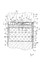
- Fig. 2
- einen Schnitt im Bereich einer Verglasungsfuge des Türblatts von
Fig. 1 (Schnitt E-E vonFig. 1 ); - Fig. 3
- eine Draufsicht eines ersten Elements einer in der Verglasungsfuge eingesetzten Rasteinrichtung;
- Fig. 4
- eine Seitenansicht auf das erste Element von links in
Fig. 3 gesehen; - Fig. 5
- eine Vorderansicht des ersten Elements;
- Fig. 6
- eine perspektivische Ansicht des ersten Elements;
- Fig. 7
- eine Draufsicht eines zweiten Elements der Rasteinrichtung;
- Fig. 8
- eine Seitenansicht des zweiten Elements von links in
Fig. 7 gesehen; - Fig. 9
- eine Vorderansicht des zweiten Elements;
- Fig. 10
- eine perspektivische Ansicht des zweiten Elements;
- Fig. 11
- eine perspektivische Darstellung einer Rahmenanordnung des Türblatts von
Fig. 1 und eines Verglasungsprofilrahmens in Explosionsdarstellung zur Darstellung der Montage der Scheibenanordnung bei der Herstellung des Türblatts; und - Fig. 12
- einen Schnitt entlang der Linie E-E- von
Fig. 1 , der eine Konstruktion gemäß einer weiteren Ausführungsform zeigt. - In den
Fig. 1 und2 ist ein Gebäudeabschlusselement 10 in Form eines Türblatts 12 für eine Brandschutztür 14 mit flächenbündiger Verglasung 15 dargestellt. Das Türblatt 12 weist eine Rahmenanordnung 16 mit einer Verglasungsöffnung 18 auf, in die zum Bilden der Verglasung 15 eine Scheibenanordnung 20 in Brandschutzausbildung eingesetzt ist. Zum Befestigen der Scheibenanordnung 20 in der Rahmenanordnung 16 ist eine Rasteinrichtung 22 vorgesehen, die vollständig innerhalb einer Verglasungsfuge 24 zwischen einer Umfangsstirnseite 26 der Scheibenanordnung 20 und einer inneren Laibungsseite 28 der Rahmenanordnung 16 aufgenommen ist. Die Scheibenanordnung 20 und die Rahmenanordnung 16 haben im Wesentlichen die gleiche Dicke, so dass die Außenseiten 20a, 20b der Scheibenanordnung 20 im Wesentlichen bündig mit den Außenseiten 16a, 16b der Rahmenanordnung sind. - Die Rahmenanordnung 16 ist als Türblatt-Rahmenkonstruktion 30 in Brandschutzausbildung ausgeführt. Die Rahmenanordnung 16 weist hierzu ein erstes Metallblech in Form eines Kastenblechs 32 aus Stahl und ein zweites Metallblech in Form eines Deckelblechs 34 aus Stahl sowie eine Isolationseinlage 36 zwischen den beiden Metallblechen 32, 34 auf. Die Isolationseinlage ist mit dem Kastenblech 32 und dem Deckelblech 34 mittels eines 1-K-PU-Klebstoffs 38 vollflächig verklebt. In anderen, hier nicht weiter dargestellten Ausführungsformen sind andere Klebstoffe zum Verkleben eingesetzt. Die Isolationseinlage 36 weist in dem die Verglasungsöffnung 18 umgebenden Randbereich Isolierstreifen 40, beispielsweise aus Kalziumsilikate enthaltenden Materialien, auf. Im Bereich der Isolierstreifen 40 befindet sich eine Trägereinrichtung 42, an welcher die Befestigung der Verglasung erfolgt.
- Die Trägereinrichtung 42 ist in dem in
Fig. 2 dargestellten Ausführungsbeispiel durch ein T-Profil 43 gebildet, welches hier einfach durch ein mehrfach abgekantetes Metallblech ausgebildet ist. Hierdurch ist eine T-Profilleiste ausgebildet, die durchgehend an der Laibungsseite 28 durchläuft und an seitlichen (nicht dargestellten) Verstärkungsprofilen verschweißt ist. - Die Rasteinrichtung 22 weist ein an der Scheibenanordnung 20 befestigtes erstes Element 44 und ein an der Rahmenanordnung 16 befestigtes zweites Element 46 auf.
- Die beiden Element 44, 46 sind miteinander durch eine Einrastbewegung quer zur Öffnungsebene der Verglasungsöffnung 18 miteinander verrastbar. Hierzu weist die Rasteinrichtung 22 einen zwischen Anschlagbereichen 48, 50 an den Elementen 44, 46 der Rasteinrichtung 22 gebildeten Anschlag 52 zum Begrenzen der Einrastbewegung auf.
- Das erste Element 44 ist mit der Scheibenanordnung 20 verbunden und ist auf deren Umfangsstirnseite 26 angeordnet. Die Scheibenanordnung 20 ist aus mehreren einzelnen Glasscheiben 54 gebildet, die miteinander verbunden sind. Die gleiche Verbindungstechnik zum Verbinden der Glasscheiben 54 kann zum Befestigen des ersten Elements 44 an der Scheibenanordnung 20 verwendet werden. Denkbar sind ein Vergießen mit der Scheibenanordnung 20 oder ein Verkleben oder dergleichen. In einer weiteren, hier nicht näher dargestellten Ausführungsform weist das erste Element 44 mehrere Vorsprünge auf, die komplementäre Fugen in der Scheibenanordnung 20 formschlüssig eingreifen, um so das erste Element 44 an der Scheibenanordnung festzuhalten.
- Zur sicheren Befestigung ist das erste Element 44 Teil eines um den gesamten Umfang der Scheibenanordnung 20 umlaufend vorhandenen Verglasungsprofilrahmens 56, der in
Fig. 11 näher dargestellt ist. Wie ausFig. 11 ersichtlich, sind dabei mehrere Rasteinrichtungen 22 pro Stirnseite vorgesehen, so dass die Scheibenanordnung 20 an jeder der vier Umfangsstirnseiten 26 mit wenigstens zwei Rasteinrichtungen 22 befestigbar ist. - Auch das zweite Element 46 ist vorzugsweise an einem Rahmen angeordnet, der innerhalb der Laibung der Verglasungsöffnung 18 umlaufend vorhanden ist und im Folgenden als Laibungsprofilrahmen 58 bezeichnet wird. In den dargestellten Ausführungsbeispielen ist jeweils die Trägereinrichtung 42 an jeder Laibungsseite 28 vorhanden und bildet je einen Rahmenholm des Laibungsprofilrahmens 58. An jeder dieser Trägereinrichtungen 42 sind, wie am besten aus
Fig. 11 ersichtlich, wenigstens zwei zweite Elemente 46 zum Bilden der mehreren Rasteinrichtungen 22 vorgesehen. Jedes zweite Element 46 ist durch mehrere Schraubbefestiger 60, hier in Form von Blechschrauben, an die Trägereinrichtung 42 fest angeschraubt. - In den dargestellten Beispielen ist das erste Element 44 als Rastelement 62 ausgebildet, das ein elastisch vorgespanntes Eingriffselement 64 aufweist. Das zweite Element 46 ist als Gegenlagerelement 66 mit einem das Eingreifelement 64 rastend aufnehmendem Erfassungselement 68 ausgebildet.
- Der genauere Aufbau des Rastelements 62 wird im Folgenden anhand der Darstellungen in den
Fig. 3 bis 6 näher erläutert. - Das das erste Element 44 bildende Rastelement 62 ist aus einem mehrfach gebogenen Metallblech 70, insbesondere Stahlblech, gebildet und weist als Eingreifelement 64 eine herausgeklinkte und herausgebogene Blechzunge 72 auf. Die Blechzunge 72 wird von einem ebenen Plattenbereich 73 des Metallblechs 70 umgeben. Anschließend den Platten bereich 73 ist das Metallblech 70 auf der gleichen Seite wie die Blechzunge 72 vorspringend hochgebogen, so dass eine Stufenflanke 74 gebildet ist, die den Anschlagbereich 48 des ersten Elements 44 bildet. Die Blechzunge 72 ist derart ausgerichtet herausgebogen, dass ein freies Ende davon zu der Stufenflanke 74 hin gerichtet ist. Auf der der Blechzunge 72 abgewandten Seite der Stufenflanke 74 schließt sich an die Stufenflanke 74 eine Anlaufschräge 76 an, die in einen mit dem Plattenbereich 73 bündig parallel auslaufenden Randstreifen 78 mündet.
- Im Folgenden wird der Aufbau des zweiten Elements 46 anhand der Darstellungen in den
Fig. 7 bis 10 näher erläutert. Das das zweite Element 46 bildende Gegenlagerelement 66 ist durch ein ebenfalls mehrfach gebogenes Metallblech 80 gebildet, welches zum Bilden einer Stufe 82 mit einer Kröpfung 84 versehen ist. Eine durch die Kröpfung 84 gebildete Stufenflanke 88 dient als Erfassungselement 68, welches von der Blechzunge 72 hintergriffen werden kann. Ein sich an die Kröpfung 84 anschließender erster Randbereich 90 ist mit Öffnungen 92 zur Aufnahme der Schraubbefestiger 60 versehen. Die Öffnungen 92 sind länglich ausgebildet, um so eine Lageeinstellung des zweiten Elements 46 vornehmen zu können. Ein sich an die Kröpfung 84 auf der anderen Seite anschließender zweiter Randbereich 94 steht im bestimmungsgemäßen Gebrauch vorspringend in die Verglasungsöffnung 18 hinein vor und wird im inFig. 2 dargestellten Rastzustand zwischen der Blechzunge 72 und der Stufenflanke 74 aufgenommen. Die freie Kante 96 des zweiten Randbereichs 94 bildet den Anschlagbereich 50 des zweiten Elements 46 der Rasteinrichtung 22. - Bei der Herstellung wird derart vorgegangen, dass die Verglasungsöffnung 18 aus einem vollflächigen Türblatt in Kasten-Deckel-Konstruktion ausgeschnitten wird. Der Laibungsbereich wird dann mit dem Isolierstreifen 40 versehen. Die Trägereinrichtung 42 wird mit den Verstärkungsprofilen und Verstärkungsträgern in die Verglasungsöffnung im Laibungsbereich eingeschweißt. Das zweite Element 46 wird mit den Schraubbefestigern 60 an dem Tragprofil 42 angeschraubt. Hierdurch entsteht die Türblatt-Rahmenkonstruktion 100 mit der Verglasungsöffnung 18 und mehreren zweiten Elementen 46, wie sie in
Fig. 11 dargestellt ist. - Die Scheibenanordnung 20 wird z.B. mit den im Herstellwerk für die Scheibenanordnung 20 befestigten ersten Elementen 44 geliefert. In
Fig. 11 ist hierzu nur der die Scheibenanordnung 20 aufnehmende Verglasungsprofilrahmen 56 mit den integral daran ausgebildeten ersten Elementen 44 noch ohne die Glasscheiben 54 dargestellt. Wenn die Scheibenanordnung 20 in dem Verglasungsprofilrahmen 56 befestigt ist, wird die Scheibenanordnung 20 der dargestellten Montagerichtung 102 senkrecht zur Öffnungsebene in die Verglasungsöffnung 18 eingeschoben, bis die Blechzunge 72 über dem durch den zweiten Randbereich 94 gebildeten Vorsprung hinweg gleitet und hinter der Stufenflanke 88 einrastet, wobei die Kante 96 an der Stufenflanke 74 des ersten Elements 44 anschlägt. - Die Verglasungsfugen 24 werden je nach Bedarf eventuell noch mit Streifen aus intumeszierendem Material versehen. Diese Streifen aus intumeszierendem Material (nicht dargestellt) können bereits vorher, insbesondere in einer Nut in einem Bereich zwischen dem T-Profil 43 und dem Kastenblech 32 oder dem Deckelblech 34 vorgesehen werden. Der verbleibende Bereich der Verglasungsfuge 24 wird von beiden Seiten her mit einem (nicht dargestellten) Dichtungsmaterial, wie beispielsweise Silikon, vergossen.
- In
Fig. 12 ist noch eine modifizierte Auführungsform eines verglasten Brandschutz-Türblattes 12 in einer Darstellung vergleichbar zu der Darstellung inFig. 2 dargestellt. Diese Ausführungsform entspricht bis auf die Ausbildung der Trägereinrichtung 42 der zuvor anhand derFig. 2 dargestellten Ausführungsform. Entsprechende Teile sind mit entsprechenden Bezugszeichen versehen. - Bei der zweiten Ausführungsform weist die Trägereinrichtung 42 zwei Winkelprofile 104 und 106 auf. Ein erstes Winkelprofil 104 ist mit einem Schenkel 104 a an dem Kastenblech 32 befestigt und ein zweites Winkelprofil 106 ist mit einem Schenkel 106a an dem Deckelblech 34 befestigt. Die verbleibenden Schenkel 104b, 106b der beiden Winkelprofile 104, 106 überlappen einander und verstärken so den Laibungsbereich der Verglasungsöffnung 18. Zwischen diesen senkrecht zur Öffnungsebene verlaufenden Schenkeln 104b, 106b ist ein Isolationsstreifen 108 aus Brandschutzmaterial eingefügt; darunter sind mehrere Lagen der Isolierstreifen 40 vorgesehen. Die Schraubbefestiger 60 durchgreifen beide überlappenden Schenkel 104b, 106b. Ansonsten ist das Aufbau der zweiten Ausführungsform gleich zu demjenigen der ersten Ausführungsform.
-
- 10
- Gebäudeabschlusselement
- 12
- Türblatt
- 14
- Brandschutztür
- 15
- Verglasung
- 16
- Rahmenanordnung
- 16a
- Außenseite
- 16b
- Außenseite
- 18
- Verglasungsöffnung
- 20
- Scheibenanordnung
- 20a
- Außenseite
- 20b
- Außenseite
- 22
- Rasteinrichtung
- 24
- Verglasungsfuge
- 26
- Umfangsstirnseite
- 28
- Laibungsseite
- 30
- Türblatt-Rahmenkonstruktion
- 32
- Kastenblech
- 34
- Deckelblech
- 36
- Isolationseinlage
- 38
- 1-K-PU-Klebstoff
- 40
- Isolierstreifen
- 42
- Trägereinrichtung
- 43
- T-Profil
- 44
- erstes Element der Rasteinrichtung
- 46
- zweites Element der Rasteinrichtung
- 48
- Anschlagbereich
- 50
- Anschlagbereich
- 52
- Anschlag
- 54
- Glasscheiben
- 56
- Verglasungsprofilrahmen
- 58
- Laibungsprofilrahmen
- 60
- Schraubbefestiger
- 62
- Rastelement
- 64
- Eingreifelement
- 66
- Gegenlagerelement
- 68
- Erfassungselement
- 70
- Metallblech (Rastelement)
- 72
- Blechzunge
- 73
- Plattenbereich
- 74
- Stufenflanke
- 76
- Anlaufschräge
- 78
- Randstreifen
- 80
- Metallblech (Gegenlagerelement)
- 82
- Stufe
- 84
- Kröpfung
- 88
- Stufenflanke
- 90
- erster Randbereich
- 92
- Öffnung
- 94
- zweiter Randbereich
- 96
- Kante
- 100
- Türblatt-Rahmenkonstruktion
- 102
- Montagerichtung
- 104
- erstes Winkelprofil
- 104a
- Schenkel
- 104b
- Schenkel
- 106
- zweites Winkelprofil
- 106a
- Schenkel
- 106b
- Schenkel
- 108
- Isolationsstreifen
Claims (16)
- Gebäudeabschlusselement (10), insbesondere Brandschutzabschlusselement, mit insbesondere flächenbündiger Verglasung (15), umfassend eine Rahmenanordnung (16) und eine in der Rahmenanordnung (16) einzusetzende Scheibenanordnung (20), gekennzeichnet durch eine Rasteinrichtung (22) zum Befestigen der Scheibenanordnung (20) in der Rahmenanordnung (16).
- Gebäudeabschlusselement (10) nach Anspruch 1,
dadurch gekennzeichnet,
dass die Rasteinrichtung (22) vollständig zwischen wenigstens einer äußeren Umfangsstirnseite (26) der Scheibenanordnung (20) und einer dieser zugewandten Laibungsstirnseite (28) einer Verglasungsöffnung (18) in der Rahmenanordnung (16) aufgenommen ist. - Gebäudeabschlusselement (10) nach einem der voranstehenden Ansprüche,
dadurch gekennzeichnet,
dass die Rasteinrichtung (22) einen Anschlag (50) zum Begrenzen einer Einrastbewegung nach erfolgtem Einrasten aufweist. - Gebäudeabschlusselement (10) nach einem der voranstehenden Ansprüche,
dadurch gekennzeichnet,
dass die Rasteinrichtung (22) ein an der Rahmenanordnung (16) oder der Scheibenanordnung (20) zu befestigendes Rastelement (62) mit einem elastisch bewegbar in eine Eingreifstellung vorgespannten Eingreifelement (64) und ein an der jeweils anderen Anordnung (20, 16) zu befestigendes Gegenlagerelement (66) mit einem das Eingreifelement (64) formschlüssig aufnehmenden Erfassungselement (68) aufweist. - Gebäudeabschlusselement (10) nach Anspruch 3 und nach Anspruch 4,
dadurch gekennzeichnet,
dass der Anschlag (50) durch aneinander anschlagende Anschlagbereiche (48, 50) an dem Rastelement (62) und dem Gegenlagerelement (66) gebildet sind. - Gebäudeabschlusselement (10) nach einem der Ansprüche 4 bis 5,
dadurch gekennzeichnet,
dass das Rastelement (62) und das Gegenlagerelement (66) aus insbesondere mehrfach gebogenen Metallblechen (70, 80) gefertigt sind. - Gebäudeabschlusselement (10) nach Anspruch 5 und nach Anspruch 6,
dadurch gekennzeichnet,
dass die Anschlagbereiche (48, 50) durch vorspringende Ausbiegungen der Metallbleche (70, 80) gebildet sind. - Gebäudeabschlusselement (10) nach einem der Ansprüche 6 oder 7,
dadurch gekennzeichnet,
dass das Eingreifelement (64) eine ausgebogene Blechzunge (72) in oder an dem Metallblech (70) des Rastelements (62) ist und dass das Erfassungselement (68) eine Stufe (82) in dem Metallblech (80) des Gegenlagerelements (66) ist. - Gebäudeschutzabschlusselement (10) nach einem der voranstehenden Ansprüche,
dadurch gekennzeichnet,
dass ein an der Scheibenanordnung (10) anzuordnendes erstes Element (44) der Rasteinrichtung (22) an einem die Scheibenanordnung (20) an deren äußeren Stirnseitenumfang umgebenden Verglasungsprofilrahmen (56) ausgebildet ist und/oder dass ein an der Rahmenanordnung (16) anzuordnendes zweites Element (46) der Rasteinrichtung (22) an einem an den Innenseiten einer die Scheibenanordnung (20) aufnehmenden Verglasungsöffnung (18) befestigten Laibungsprofilrahmen (58) ausgebildet oder befestigt ist. - Gebäudeabschlusselement (10) nach einem der voranstehenden Ansprüche,
dadurch gekennzeichnet,
dass ein an der Scheibenanordnung (20) anzuordnendes Element (44) der Rasteinrichtung (22) an wenigstens einer Stirnseite (20) der Scheibenanordnung (20) befestigt ist, insbesondere durch Eingießen, Verkleben und/oder Formschlusseingriff. - Gebäudeabschlusselement (10) nach einem der voranstehenden Ansprüche
dadurch gekennzeichnet,
dass ein an der Rahmenanordnung (16) anzuordnendes Element (46) der Rasteinrichtung durch eine Mehrzahl von Schraub- oder Nietbefestigern (60) an der Rahmenanordnung (16) befestigt ist. - Gebäudeabschlusselement (10) nach einem der voranstehenden Ansprüche,
dadurch gekennzeichnet,
dass die Außenseiten (20a, 20b) der Scheibenanordnung (20) im Wesentlichen flächenbündig mit den Außenseiten (16a, 16b) der Rahmenanordnung (16) sind. - Gebäudeabschlusselement (10) nach einem der voranstehenden Ansprüche,
gekennzeichnet durch eine Ausbildung als Türblatt (12), insbesondere einer Brandschutztür (14), wobei die Rahmenanordnung (16) ein Türblattrahmen oder ein Türblattelement (100) mit Verglasungsausschnitt ist, in den die Scheibenanordnung (20) mittels der Rasteinrichtung (22) einrastend befestigt gehalten ist. - Gebäudeabschlusselement (10) nach Anspruch 13,
dadurch gekennzeichnet,
dass das Türblattelement (100), insbesondere in Kasten-Deckelblechbauweise, mit zwei die Außenseiten (16a, 16b) bildenden Metallblechen (32, 34) und einer Isolationseinlage (36) dazwischen ausgebildet ist. - Gebäudeabschlusselement (10) nach Anspruch 14,
dadurch gekennzeichnet,
dass die Isolationseinlage (36) durch großflächige Verklebungen (38) mit den Metallblechen (32, 34) verbunden sind. - Verfahren zum Herstellen eines Gebäudeabschlusselementes (10) mit flächenbündiger Verglasung (15),
gekennzeichnet durcha) Befestigen eines ersten Elements (44) einer Rasteinrichtung (22) an einer Scheibenanordnung (20),b) Befestigen eines zweiten Elements (46) der Rasteinrichtung (22) an einer Verglasungsöffnung (18) in einer Rahmenanordnung (16),c) Einsetzen der Scheibenanordnung (20) in die Verglasungsöffnung (18) undd) Befestigen der Scheibenanordnung (20) in der Verglasungsöffnung (18) durch Einrasten der Rasteinrichtung (22).
Priority Applications (1)
| Application Number | Priority Date | Filing Date | Title |
|---|---|---|---|
| PL11150036T PL2348184T3 (pl) | 2010-01-26 | 2011-01-03 | Element zamknięcia budynku wyposażony w szklane wypełnienie oraz sposób wytwarzania |
Applications Claiming Priority (1)
| Application Number | Priority Date | Filing Date | Title |
|---|---|---|---|
| DE102010005719.3A DE102010005719B4 (de) | 2010-01-26 | 2010-01-26 | Gebäudeabschlusselement mit Verglasung sowie Herstellverfahren |
Publications (3)
| Publication Number | Publication Date |
|---|---|
| EP2348184A2 true EP2348184A2 (de) | 2011-07-27 |
| EP2348184A3 EP2348184A3 (de) | 2014-11-05 |
| EP2348184B1 EP2348184B1 (de) | 2017-07-26 |
Family
ID=43920406
Family Applications (1)
| Application Number | Title | Priority Date | Filing Date |
|---|---|---|---|
| EP11150036.9A Active EP2348184B1 (de) | 2010-01-26 | 2011-01-03 | Gebäudeabschlusselement mit Verglasung sowie Herstellverfahren |
Country Status (4)
| Country | Link |
|---|---|
| EP (1) | EP2348184B1 (de) |
| DE (1) | DE102010005719B4 (de) |
| ES (1) | ES2645196T3 (de) |
| PL (1) | PL2348184T3 (de) |
Cited By (1)
| Publication number | Priority date | Publication date | Assignee | Title |
|---|---|---|---|---|
| AT519252B1 (de) * | 2017-06-16 | 2018-05-15 | Peneder Bau Elemente Gmbh | Haltevorrichtung |
Families Citing this family (4)
| Publication number | Priority date | Publication date | Assignee | Title |
|---|---|---|---|---|
| DE202016101223U1 (de) * | 2016-03-07 | 2017-06-08 | Holzbau Schmid Gmbh & Co. Kg | Einrichtung zum Schließen einer Öffnung für Brandschutzzwecke |
| DE102016114966A1 (de) | 2016-08-11 | 2018-02-15 | Hörmann KG Freisen | Hinterfütterungsvorrichtung sowie damit versehene Umfassungszarge |
| DE102016125819B4 (de) | 2016-12-28 | 2021-09-30 | Hörmann KG Freisen | Hinterfütterungsvorrichtung sowie damit versehene Umfassungszarge |
| DE102018117112A1 (de) | 2018-07-16 | 2020-01-16 | Hörmann Kg Brandis | Gebäudeabschlusselement und Verfahren zum Herstellen eines Gebäudeabschlusselements |
Citations (1)
| Publication number | Priority date | Publication date | Assignee | Title |
|---|---|---|---|---|
| EP1586734A2 (de) | 2004-04-14 | 2005-10-19 | HÖRMANN KG Freisen | Verglastes Feuerschutz-Türblatt sowie System und Verfahren zur Herstellung desselben |
Family Cites Families (5)
| Publication number | Priority date | Publication date | Assignee | Title |
|---|---|---|---|---|
| GB9205084D0 (en) * | 1992-03-09 | 1992-04-22 | Briggs Leslie G | A glazing construction |
| FR2736962B1 (fr) * | 1995-06-02 | 1997-08-14 | Saint Gobain Vitrage | Systeme de fixation d'un vitrage dans une baie |
| GB9705410D0 (en) * | 1997-03-15 | 1997-04-30 | Taylor Graham C | A retaining device for a glazed unit and a glazed unit including such a retaining device |
| DE20317163U1 (de) * | 2003-11-04 | 2004-01-15 | Rosenheimer Glastechnik Gmbh | Befestigungssystem mit Schwenkelement zum Befestigen eines mindestens eine Glasscheibe enthaltenden flächigen Scheibenelementes |
| SE531015C2 (sv) * | 2007-12-17 | 2008-11-18 | Steelform Scandinavia Ab | Anordning för säkring av fönsterparti |
-
2010
- 2010-01-26 DE DE102010005719.3A patent/DE102010005719B4/de active Active
-
2011
- 2011-01-03 EP EP11150036.9A patent/EP2348184B1/de active Active
- 2011-01-03 PL PL11150036T patent/PL2348184T3/pl unknown
- 2011-01-03 ES ES11150036.9T patent/ES2645196T3/es active Active
Patent Citations (1)
| Publication number | Priority date | Publication date | Assignee | Title |
|---|---|---|---|---|
| EP1586734A2 (de) | 2004-04-14 | 2005-10-19 | HÖRMANN KG Freisen | Verglastes Feuerschutz-Türblatt sowie System und Verfahren zur Herstellung desselben |
Cited By (2)
| Publication number | Priority date | Publication date | Assignee | Title |
|---|---|---|---|---|
| AT519252B1 (de) * | 2017-06-16 | 2018-05-15 | Peneder Bau Elemente Gmbh | Haltevorrichtung |
| AT519252A4 (de) * | 2017-06-16 | 2018-05-15 | Peneder Bau Elemente Gmbh | Haltevorrichtung |
Also Published As
| Publication number | Publication date |
|---|---|
| EP2348184B1 (de) | 2017-07-26 |
| DE102010005719A1 (de) | 2011-07-28 |
| ES2645196T3 (es) | 2017-12-04 |
| EP2348184A3 (de) | 2014-11-05 |
| DE102010005719B4 (de) | 2014-01-30 |
| PL2348184T3 (pl) | 2017-12-29 |
Similar Documents
| Publication | Publication Date | Title |
|---|---|---|
| EP1555376A1 (de) | Verbundprofilanordnung | |
| EP2348184B1 (de) | Gebäudeabschlusselement mit Verglasung sowie Herstellverfahren | |
| DE102021120099A1 (de) | Türflügel, insbesondere für eine Haustür | |
| DE102004038246B4 (de) | Vorrichtung zur Montage eines Fensterelementes o. dgl. Baugruppen | |
| EP1835120A1 (de) | Wohndachfenter mit Verstellfalz | |
| DE19718714A1 (de) | Isolierelement aus zwei oder mehreren, aus Glas oder Kunststoff gefertigten Scheiben | |
| AT507318B1 (de) | Sockelprofilleiste für dämmplatten | |
| DE19758464C2 (de) | Isolierelement aus wenigstens zwei Glas- oder Kunststoffscheiben und mit Profilschienen oder -teilen zur Montage in einem Rahmen | |
| EP3692611B1 (de) | Anordnung zur positionierung eines flachteils an einem schaltschrankrahmengestell sowie ein entsprechendes verfahren | |
| EP4191011B1 (de) | Rahmenteil und daraus hergestellter membranrahmen | |
| DE102019133839A1 (de) | Bauelement in Brandschutzausführung und Verfahren zur Montage eines Bauelementes | |
| DE102020101582A1 (de) | Türflügel sowie tür mit einem blendrahmen und einem türflügel | |
| DE4216685C1 (en) | Window ledge structure in building - has connecting profile at end facing window soffit having accommodation groove open to ledge and extending longitudinally | |
| DE29818846U1 (de) | Fenster- oder Türflügel | |
| EP2593319B1 (de) | Fensterscheibe und verfahren zum montieren einer fensterscheibe an einem fahrzeug | |
| AT402530B (de) | Türflügel für gebäudeaussentür | |
| DE29707789U1 (de) | Fassade | |
| EP3284872A1 (de) | Dichtelement zum anschliessen einer trockenbauwand | |
| EP1333144B1 (de) | Tür mit Profilnut | |
| EP3770373A1 (de) | Montageeinheit und verfahren zur montage eines kastens zur aufnahme eines rollladens oder eines sonnenschutzes an einem blendrahmen | |
| AT508271B1 (de) | Abschlussteil zum seitlichen abschliessen einer abdeckschiene | |
| EP3346085B1 (de) | Gebäudeabschlusselement und verfahren zur montage desselben | |
| EP3477034B1 (de) | Flügel für ein fenster oder eine tür | |
| AT521784B1 (de) | Verkleidung für eine Wandöffnung | |
| AT502155B1 (de) | Rahmenloses isolierglaselement sowie beschlag- oder befestigungssystem für das isolierglaselement |
Legal Events
| Date | Code | Title | Description |
|---|---|---|---|
| PUAI | Public reference made under article 153(3) epc to a published international application that has entered the european phase |
Free format text: ORIGINAL CODE: 0009012 |
|
| AK | Designated contracting states |
Kind code of ref document: A2 Designated state(s): AL AT BE BG CH CY CZ DE DK EE ES FI FR GB GR HR HU IE IS IT LI LT LU LV MC MK MT NL NO PL PT RO RS SE SI SK SM TR |
|
| AX | Request for extension of the european patent |
Extension state: BA ME |
|
| PUAL | Search report despatched |
Free format text: ORIGINAL CODE: 0009013 |
|
| AK | Designated contracting states |
Kind code of ref document: A3 Designated state(s): AL AT BE BG CH CY CZ DE DK EE ES FI FR GB GR HR HU IE IS IT LI LT LU LV MC MK MT NL NO PL PT RO RS SE SI SK SM TR |
|
| AX | Request for extension of the european patent |
Extension state: BA ME |
|
| RIC1 | Information provided on ipc code assigned before grant |
Ipc: E06B 3/58 20060101AFI20140926BHEP |
|
| 17P | Request for examination filed |
Effective date: 20150505 |
|
| RBV | Designated contracting states (corrected) |
Designated state(s): AL AT BE BG CH CY CZ DE DK EE ES FI FR GB GR HR HU IE IS IT LI LT LU LV MC MK MT NL NO PL PT RO RS SE SI SK SM TR |
|
| 17Q | First examination report despatched |
Effective date: 20160414 |
|
| GRAP | Despatch of communication of intention to grant a patent |
Free format text: ORIGINAL CODE: EPIDOSNIGR1 |
|
| INTG | Intention to grant announced |
Effective date: 20170222 |
|
| GRAS | Grant fee paid |
Free format text: ORIGINAL CODE: EPIDOSNIGR3 |
|
| GRAA | (expected) grant |
Free format text: ORIGINAL CODE: 0009210 |
|
| AK | Designated contracting states |
Kind code of ref document: B1 Designated state(s): AL AT BE BG CH CY CZ DE DK EE ES FI FR GB GR HR HU IE IS IT LI LT LU LV MC MK MT NL NO PL PT RO RS SE SI SK SM TR |
|
| REG | Reference to a national code |
Ref country code: GB Ref legal event code: FG4D Free format text: NOT ENGLISH |
|
| REG | Reference to a national code |
Ref country code: CH Ref legal event code: EP |
|
| REG | Reference to a national code |
Ref country code: AT Ref legal event code: REF Ref document number: 912544 Country of ref document: AT Kind code of ref document: T Effective date: 20170815 |
|
| REG | Reference to a national code |
Ref country code: IE Ref legal event code: FG4D Free format text: LANGUAGE OF EP DOCUMENT: GERMAN |
|
| REG | Reference to a national code |
Ref country code: DE Ref legal event code: R096 Ref document number: 502011012674 Country of ref document: DE |
|
| REG | Reference to a national code |
Ref country code: NL Ref legal event code: MP Effective date: 20170726 |
|
| REG | Reference to a national code |
Ref country code: ES Ref legal event code: FG2A Ref document number: 2645196 Country of ref document: ES Kind code of ref document: T3 Effective date: 20171204 |
|
| REG | Reference to a national code |
Ref country code: LT Ref legal event code: MG4D |
|
| REG | Reference to a national code |
Ref country code: FR Ref legal event code: PLFP Year of fee payment: 8 |
|
| PG25 | Lapsed in a contracting state [announced via postgrant information from national office to epo] |
Ref country code: NO Free format text: LAPSE BECAUSE OF FAILURE TO SUBMIT A TRANSLATION OF THE DESCRIPTION OR TO PAY THE FEE WITHIN THE PRESCRIBED TIME-LIMIT Effective date: 20171026 Ref country code: LT Free format text: LAPSE BECAUSE OF FAILURE TO SUBMIT A TRANSLATION OF THE DESCRIPTION OR TO PAY THE FEE WITHIN THE PRESCRIBED TIME-LIMIT Effective date: 20170726 Ref country code: SE Free format text: LAPSE BECAUSE OF FAILURE TO SUBMIT A TRANSLATION OF THE DESCRIPTION OR TO PAY THE FEE WITHIN THE PRESCRIBED TIME-LIMIT Effective date: 20170726 Ref country code: FI Free format text: LAPSE BECAUSE OF FAILURE TO SUBMIT A TRANSLATION OF THE DESCRIPTION OR TO PAY THE FEE WITHIN THE PRESCRIBED TIME-LIMIT Effective date: 20170726 Ref country code: HR Free format text: LAPSE BECAUSE OF FAILURE TO SUBMIT A TRANSLATION OF THE DESCRIPTION OR TO PAY THE FEE WITHIN THE PRESCRIBED TIME-LIMIT Effective date: 20170726 Ref country code: NL Free format text: LAPSE BECAUSE OF FAILURE TO SUBMIT A TRANSLATION OF THE DESCRIPTION OR TO PAY THE FEE WITHIN THE PRESCRIBED TIME-LIMIT Effective date: 20170726 |
|
| PG25 | Lapsed in a contracting state [announced via postgrant information from national office to epo] |
Ref country code: LV Free format text: LAPSE BECAUSE OF FAILURE TO SUBMIT A TRANSLATION OF THE DESCRIPTION OR TO PAY THE FEE WITHIN THE PRESCRIBED TIME-LIMIT Effective date: 20170726 Ref country code: BG Free format text: LAPSE BECAUSE OF FAILURE TO SUBMIT A TRANSLATION OF THE DESCRIPTION OR TO PAY THE FEE WITHIN THE PRESCRIBED TIME-LIMIT Effective date: 20171026 Ref country code: IS Free format text: LAPSE BECAUSE OF FAILURE TO SUBMIT A TRANSLATION OF THE DESCRIPTION OR TO PAY THE FEE WITHIN THE PRESCRIBED TIME-LIMIT Effective date: 20171126 Ref country code: GR Free format text: LAPSE BECAUSE OF FAILURE TO SUBMIT A TRANSLATION OF THE DESCRIPTION OR TO PAY THE FEE WITHIN THE PRESCRIBED TIME-LIMIT Effective date: 20171027 Ref country code: RS Free format text: LAPSE BECAUSE OF FAILURE TO SUBMIT A TRANSLATION OF THE DESCRIPTION OR TO PAY THE FEE WITHIN THE PRESCRIBED TIME-LIMIT Effective date: 20170726 |
|
| PG25 | Lapsed in a contracting state [announced via postgrant information from national office to epo] |
Ref country code: RO Free format text: LAPSE BECAUSE OF FAILURE TO SUBMIT A TRANSLATION OF THE DESCRIPTION OR TO PAY THE FEE WITHIN THE PRESCRIBED TIME-LIMIT Effective date: 20170726 Ref country code: CZ Free format text: LAPSE BECAUSE OF FAILURE TO SUBMIT A TRANSLATION OF THE DESCRIPTION OR TO PAY THE FEE WITHIN THE PRESCRIBED TIME-LIMIT Effective date: 20170726 Ref country code: DK Free format text: LAPSE BECAUSE OF FAILURE TO SUBMIT A TRANSLATION OF THE DESCRIPTION OR TO PAY THE FEE WITHIN THE PRESCRIBED TIME-LIMIT Effective date: 20170726 |
|
| REG | Reference to a national code |
Ref country code: DE Ref legal event code: R097 Ref document number: 502011012674 Country of ref document: DE |
|
| PG25 | Lapsed in a contracting state [announced via postgrant information from national office to epo] |
Ref country code: EE Free format text: LAPSE BECAUSE OF FAILURE TO SUBMIT A TRANSLATION OF THE DESCRIPTION OR TO PAY THE FEE WITHIN THE PRESCRIBED TIME-LIMIT Effective date: 20170726 Ref country code: SK Free format text: LAPSE BECAUSE OF FAILURE TO SUBMIT A TRANSLATION OF THE DESCRIPTION OR TO PAY THE FEE WITHIN THE PRESCRIBED TIME-LIMIT Effective date: 20170726 Ref country code: SM Free format text: LAPSE BECAUSE OF FAILURE TO SUBMIT A TRANSLATION OF THE DESCRIPTION OR TO PAY THE FEE WITHIN THE PRESCRIBED TIME-LIMIT Effective date: 20170726 |
|
| PLBE | No opposition filed within time limit |
Free format text: ORIGINAL CODE: 0009261 |
|
| STAA | Information on the status of an ep patent application or granted ep patent |
Free format text: STATUS: NO OPPOSITION FILED WITHIN TIME LIMIT |
|
| 26N | No opposition filed |
Effective date: 20180430 |
|
| PG25 | Lapsed in a contracting state [announced via postgrant information from national office to epo] |
Ref country code: SI Free format text: LAPSE BECAUSE OF FAILURE TO SUBMIT A TRANSLATION OF THE DESCRIPTION OR TO PAY THE FEE WITHIN THE PRESCRIBED TIME-LIMIT Effective date: 20170726 |
|
| REG | Reference to a national code |
Ref country code: CH Ref legal event code: PL |
|
| GBPC | Gb: european patent ceased through non-payment of renewal fee |
Effective date: 20180103 |
|
| PG25 | Lapsed in a contracting state [announced via postgrant information from national office to epo] |
Ref country code: MT Free format text: LAPSE BECAUSE OF FAILURE TO SUBMIT A TRANSLATION OF THE DESCRIPTION OR TO PAY THE FEE WITHIN THE PRESCRIBED TIME-LIMIT Effective date: 20170726 |
|
| PG25 | Lapsed in a contracting state [announced via postgrant information from national office to epo] |
Ref country code: LU Free format text: LAPSE BECAUSE OF NON-PAYMENT OF DUE FEES Effective date: 20180103 |
|
| REG | Reference to a national code |
Ref country code: IE Ref legal event code: MM4A |
|
| REG | Reference to a national code |
Ref country code: BE Ref legal event code: MM Effective date: 20180131 |
|
| PG25 | Lapsed in a contracting state [announced via postgrant information from national office to epo] |
Ref country code: BE Free format text: LAPSE BECAUSE OF NON-PAYMENT OF DUE FEES Effective date: 20180131 Ref country code: CH Free format text: LAPSE BECAUSE OF NON-PAYMENT OF DUE FEES Effective date: 20180131 Ref country code: GB Free format text: LAPSE BECAUSE OF NON-PAYMENT OF DUE FEES Effective date: 20180103 Ref country code: LI Free format text: LAPSE BECAUSE OF NON-PAYMENT OF DUE FEES Effective date: 20180131 |
|
| PG25 | Lapsed in a contracting state [announced via postgrant information from national office to epo] |
Ref country code: IE Free format text: LAPSE BECAUSE OF NON-PAYMENT OF DUE FEES Effective date: 20180103 |
|
| PG25 | Lapsed in a contracting state [announced via postgrant information from national office to epo] |
Ref country code: MC Free format text: LAPSE BECAUSE OF FAILURE TO SUBMIT A TRANSLATION OF THE DESCRIPTION OR TO PAY THE FEE WITHIN THE PRESCRIBED TIME-LIMIT Effective date: 20170726 |
|
| PG25 | Lapsed in a contracting state [announced via postgrant information from national office to epo] |
Ref country code: TR Free format text: LAPSE BECAUSE OF FAILURE TO SUBMIT A TRANSLATION OF THE DESCRIPTION OR TO PAY THE FEE WITHIN THE PRESCRIBED TIME-LIMIT Effective date: 20170726 |
|
| PG25 | Lapsed in a contracting state [announced via postgrant information from national office to epo] |
Ref country code: HU Free format text: LAPSE BECAUSE OF FAILURE TO SUBMIT A TRANSLATION OF THE DESCRIPTION OR TO PAY THE FEE WITHIN THE PRESCRIBED TIME-LIMIT; INVALID AB INITIO Effective date: 20110103 Ref country code: PT Free format text: LAPSE BECAUSE OF FAILURE TO SUBMIT A TRANSLATION OF THE DESCRIPTION OR TO PAY THE FEE WITHIN THE PRESCRIBED TIME-LIMIT Effective date: 20170726 |
|
| PG25 | Lapsed in a contracting state [announced via postgrant information from national office to epo] |
Ref country code: MK Free format text: LAPSE BECAUSE OF NON-PAYMENT OF DUE FEES Effective date: 20170726 Ref country code: CY Free format text: LAPSE BECAUSE OF FAILURE TO SUBMIT A TRANSLATION OF THE DESCRIPTION OR TO PAY THE FEE WITHIN THE PRESCRIBED TIME-LIMIT Effective date: 20170726 |
|
| PG25 | Lapsed in a contracting state [announced via postgrant information from national office to epo] |
Ref country code: AL Free format text: LAPSE BECAUSE OF FAILURE TO SUBMIT A TRANSLATION OF THE DESCRIPTION OR TO PAY THE FEE WITHIN THE PRESCRIBED TIME-LIMIT Effective date: 20170726 |
|
| P01 | Opt-out of the competence of the unified patent court (upc) registered |
Effective date: 20230512 |
|
| PGFP | Annual fee paid to national office [announced via postgrant information from national office to epo] |
Ref country code: PL Payment date: 20251219 Year of fee payment: 16 |
|
| PGFP | Annual fee paid to national office [announced via postgrant information from national office to epo] |
Ref country code: ES Payment date: 20260217 Year of fee payment: 16 |
|
| PGFP | Annual fee paid to national office [announced via postgrant information from national office to epo] |
Ref country code: DE Payment date: 20260320 Year of fee payment: 16 |
|
| PGFP | Annual fee paid to national office [announced via postgrant information from national office to epo] |
Ref country code: AT Payment date: 20260123 Year of fee payment: 16 |
|
| PGFP | Annual fee paid to national office [announced via postgrant information from national office to epo] |
Ref country code: IT Payment date: 20260130 Year of fee payment: 16 |
|
| PGFP | Annual fee paid to national office [announced via postgrant information from national office to epo] |
Ref country code: FR Payment date: 20260121 Year of fee payment: 16 |