EP2353641A1 - Implantierbare aktive medizinische Vorrichtung zur Resynchronisation des Herzens mit automatischer Echtzeit-Optimierung der interventrikulären und atrioventrikulären Verzögerungen - Google Patents
Implantierbare aktive medizinische Vorrichtung zur Resynchronisation des Herzens mit automatischer Echtzeit-Optimierung der interventrikulären und atrioventrikulären Verzögerungen Download PDFInfo
- Publication number
- EP2353641A1 EP2353641A1 EP10192940A EP10192940A EP2353641A1 EP 2353641 A1 EP2353641 A1 EP 2353641A1 EP 10192940 A EP10192940 A EP 10192940A EP 10192940 A EP10192940 A EP 10192940A EP 2353641 A1 EP2353641 A1 EP 2353641A1
- Authority
- EP
- European Patent Office
- Prior art keywords
- dvv
- dav
- error signal
- signal
- sensor
- Prior art date
- Legal status (The legal status is an assumption and is not a legal conclusion. Google has not performed a legal analysis and makes no representation as to the accuracy of the status listed.)
- Granted
Links
Images



Classifications
-
- A—HUMAN NECESSITIES
- A61—MEDICAL OR VETERINARY SCIENCE; HYGIENE
- A61N—ELECTROTHERAPY; MAGNETOTHERAPY; RADIATION THERAPY; ULTRASOUND THERAPY
- A61N1/00—Electrotherapy; Circuits therefor
- A61N1/18—Applying electric currents by contact electrodes
- A61N1/32—Applying electric currents by contact electrodes alternating or intermittent currents
- A61N1/36—Applying electric currents by contact electrodes alternating or intermittent currents for stimulation
- A61N1/362—Heart stimulators
- A61N1/3627—Heart stimulators for treating a mechanical deficiency of the heart, e.g. congestive heart failure or cardiomyopathy
-
- A—HUMAN NECESSITIES
- A61—MEDICAL OR VETERINARY SCIENCE; HYGIENE
- A61N—ELECTROTHERAPY; MAGNETOTHERAPY; RADIATION THERAPY; ULTRASOUND THERAPY
- A61N1/00—Electrotherapy; Circuits therefor
- A61N1/18—Applying electric currents by contact electrodes
- A61N1/32—Applying electric currents by contact electrodes alternating or intermittent currents
- A61N1/36—Applying electric currents by contact electrodes alternating or intermittent currents for stimulation
- A61N1/362—Heart stimulators
- A61N1/365—Heart stimulators controlled by a physiological parameter, e.g. heart potential
- A61N1/36514—Heart stimulators controlled by a physiological parameter, e.g. heart potential controlled by a physiological quantity other than heart potential, e.g. blood pressure
-
- A—HUMAN NECESSITIES
- A61—MEDICAL OR VETERINARY SCIENCE; HYGIENE
- A61N—ELECTROTHERAPY; MAGNETOTHERAPY; RADIATION THERAPY; ULTRASOUND THERAPY
- A61N1/00—Electrotherapy; Circuits therefor
- A61N1/18—Applying electric currents by contact electrodes
- A61N1/32—Applying electric currents by contact electrodes alternating or intermittent currents
- A61N1/36—Applying electric currents by contact electrodes alternating or intermittent currents for stimulation
- A61N1/362—Heart stimulators
- A61N1/365—Heart stimulators controlled by a physiological parameter, e.g. heart potential
- A61N1/368—Heart stimulators controlled by a physiological parameter, e.g. heart potential comprising more than one electrode co-operating with different heart regions
- A61N1/3684—Heart stimulators controlled by a physiological parameter, e.g. heart potential comprising more than one electrode co-operating with different heart regions for stimulating the heart at multiple sites of the ventricle or the atrium
- A61N1/36843—Bi-ventricular stimulation
-
- A—HUMAN NECESSITIES
- A61—MEDICAL OR VETERINARY SCIENCE; HYGIENE
- A61N—ELECTROTHERAPY; MAGNETOTHERAPY; RADIATION THERAPY; ULTRASOUND THERAPY
- A61N1/00—Electrotherapy; Circuits therefor
- A61N1/18—Applying electric currents by contact electrodes
- A61N1/32—Applying electric currents by contact electrodes alternating or intermittent currents
- A61N1/36—Applying electric currents by contact electrodes alternating or intermittent currents for stimulation
- A61N1/362—Heart stimulators
- A61N1/365—Heart stimulators controlled by a physiological parameter, e.g. heart potential
- A61N1/368—Heart stimulators controlled by a physiological parameter, e.g. heart potential comprising more than one electrode co-operating with different heart regions
- A61N1/3682—Heart stimulators controlled by a physiological parameter, e.g. heart potential comprising more than one electrode co-operating with different heart regions with a variable atrioventricular delay
Definitions
- the invention relates to "active implantable medical devices" as defined by Council Directive 90/385 / EEC of 20 June 1990.
- CTR Cardiac Resynchronization Therapy
- BVP Bi-Ventricular Pacing
- a CRT stimulator is disclosed in the EP 1 108 446 A1 (ELA Medical), which describes a device for applying between the respective instants of stimulation of the left and right ventricles a so-called variable delay delay (DVV or VVD), adjusted so as to resynchronize the contraction of the ventricles with fine optimization the patient's hemodynamic status.
- ELA Medical ELA Medical
- VV or VVD variable delay delay
- a simultaneous stimulation of the two ventricles is not always optimal, because it does not necessarily lead to a synchronous contraction of the two ventricles due, on the one hand, conduction delays within the myocardium that are not the same on the right and left and may depend on multiple factors and on the other hand, the location of the left ventricular lead, depending on whether it is a probe threaded into the coronary sinus or an epicardial probe. It is therefore desirable to establish a delay between the two stimulations, and to adjust this delay to resynchronize the contraction of the ventricles and thus ensure a fine optimization of the hemodynamics.
- DVV may be null, positive (the left ventricle is stimulated after the right ventricle), or negative (the right ventricle is stimulated after the left ventricle).
- CRT devices further include a conventional "dual chamber” mode of operation in which the device monitors ventricular activity following a spontaneous atrial (sensing of an atrial depolarization P wave) or stimulated (application of an A pulse of atrial stimulation). At the same time, the device starts to count a delay called “atrioventricular delay” or “atrioventricular delay” (AVD or AVD) such that if no spontaneous ventricular activity (R wave) has was detected at the end of this time, then the device triggers a stimulation of this ventricle (application of a pulse V).
- atrioventricular delay or atrioventricular delay
- the standard technique for adjusting CRT pacing parameters is evaluation by echocardiography with estimation of the characteristic systolic delays, in particular the opening time of the aortic valve.
- this procedure must be carried out in hospitals and by qualified personnel, it is long and costly and can not be applied as often as it would be useful or necessary without interfering with the patient's daily life, despite the beneficial effects of CRT therapy.
- Another difficulty inherent in the echocardiographic evaluation is that it requires successively testing several stimulation configurations, determining for each an optimal VAD.
- the number of combinations to be tested is therefore important, and involves a procedure that is cumbersome, time-consuming and difficult to manage, which precludes making it a routine operation.
- the considered optimal value of the AVD is that of the point of inflection of the characteristic, corresponding to a maximum filling time of the ventricle without truncation of the A wave (minimal delay between the closure of the mitral valve and the beginning of the QRS complex ).
- Another disadvantage of this optimization technique is that the search for each delay (DAV or DVV) is done independently of the other: for a given DVV a scan of the DAV will give an optimal VAD locally, but (as we will be explained in more detail later with reference in particular to Figure 5 ) convergence towards a local optimum does not necessarily lead to the global optimum.
- the optimal ⁇ DAV, DVV ⁇ pair does not necessarily correspond to an optimal AVV value at constant DVV, nor to an optimal DVV value at constant AVD.
- the WO 2008/010220 describes yet another technique, which is a refinement of the previous one.
- the spike neural processor is combined with a Q-learning algorithm , which learns and associates cardiac conditions with optimal delays.
- the use of this enhanced learning makes it possible to reinforce noise immunity and to increase the convergence speed of the servo algorithm.
- this enhanced learning requires additional dedicated hardware resources, including the addition of a microcontroller in addition to the spike neural processor .
- the object of the invention is to overcome the disadvantages described above by proposing a new simple, fast, automated and efficient technique making it possible to simultaneously optimize the two parameters DAV and DVV, and this despite the interdependent character of these two parameters.
- the technique of the invention can be applied almost in real time, that is to say with a response time of only a few cardiac cycles, and by implementing only simple hardware and software means , completely compatible with what is available within a current cardiac implant.
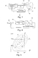
- This hemodynamic surface characterizes the system formed by the set: device CRT + patient's heart + hemodynamic sensor, and represents a function that varies according to the AVDs and DVVs programmed in the CRT device, as well as the state of the patient and the patient. sensor used.
- the invention also proposes to apply the theory of the enslavement of discrete systems, by using, to ensure the tracking or tracking of the optimal hemodynamic point on the hemodynamic surface, a conventional PID type digital controller, thus requiring only material means and / or limited software.
- an active medical device comprising a medical device of known type comprising: an implantable cardiac prosthesis resynchronizing biventricular pacing, comprising means for detecting atrial and ventricular events and means for stimulating the right ventricles and left; a sensor adapted to deliver a signal representative of a current hemodynamic parameter of the patient; means for applying to the stimulation means a AV atrioventricular delay counted from the detection of a spontaneous or stimulated atrial event and at the end of which stimulation of the right ventricle is applied in the absence of a ventricular event spontaneous detected; means for applying to the stimulation means a DVV inter-ventricular delay between the respective instants of stimulation of the right and left ventricles; and servo-control means, able to continuously control the AVD and the DVV according to the hemodynamic signal delivered by the sensor.
- the servo-control means comprise: DAV error signal generator means able to generate, as a function of the signal delivered by the at least one sensor, a representative error signal of DAV; a discrepancy between the current value of the AVS and an optimal AVD value; DVV error signal generating means capable of generating, as a function of the signal delivered by said at least one sensor, a DVV error signal representative of a difference between the current value of the DVV and an optimal value of DVV ; a closed-loop control regulator of the VAD, receiving as input said VAD error signal and outputting a VAD signal; and a closed-loop control regulator of the DVV, receiving as input said DVV error signal and outputting a DVV signal.
- the closed loop controllers of the DAV control and the control of the DVV are PID type regulators.
- one of said DAV or DVV error signal generating means comprises controlled modulation and demodulation means of the AVD or DVV, respectively.
- the respective modulation means controlled and demodulated DVV and DAV are then functionally interdependent means.
- the means for controlled modulation and demodulation of the DVV and the DAV, as well as the control regulators of the AVD and the DVV are means operating for the alternating control respectively of the AVD and of the DVV over a predetermined number of cardiac cycles, the DAV control regulator being inoperative during the modulation / demodulation of the DVV, and vice versa.
- the invention can be implemented by appropriate programming of the control software of a known pacemaker, for example of pacemaker, resynchronizer and / or defibrillator type, comprising means of acquisition of a signal provided by endocardial probes and / or one or more implanted sensors.
- the invention can in particular be applied to implantable devices such as those of the Paradym CRT family produced and marketed by Sorin CRM, Montrouge, France.
- the reference 10 designates the generator of the CRT device, which is interfaced with the heart by means of probes making it possible to detect the depolarization signals of the myocardium and stimulate it by delivering pulses to the various cavities: a probe 12 implanted in the right atrium (AR) and a probe 14 implanted in the right ventricle (VR) can optimize the AV atrioventricular delay between the stimulation times of the atrium and the right ventricle, while a probe 16 implanted in the vicinity of the ventricle left (VL) allows, in combination with the probe 14 implanted in the right ventricle, to optimize the DVV interventricular delay between the left and right ventricles.
- AR right atrium
- VR right ventricle
- VL ventricle left
- a hemodynamic sensor 18 measures a quantity correlated with the cardiac output.
- Hemodynamic sensors are sensors for estimating changes in contractility, correlated with increases in blood pressure. They are distinguished from activity sensors (acceleration sensors for example) and metabolic sensors (eg minute ventilation sensors), which are only intended to diagnose the presence or absence of exercise by the patient and to quantify its metabolic needs, for example to adapt the pacing heart rate according to the detected level.
- activity sensors acceleration sensors for example
- metabolic sensors eg minute ventilation sensors
- hemodynamic sensors can not only monitor the patient's efforts such as activity and metabolic sensors, but also give an indication of the hemodynamic tolerance of the patient in relation to certain events, in particular the tolerance to a modification of the parameters. DAV and DVV by the device.
- an example of a hemodynamic sensor will be an intracardiac pressure to determine the pressure difference ⁇ pp between the systolic pressure and the diastolic pressure, ie an endocardial endocardial acceleration sensor of PEA (Peak Endocardial Acceleration) type.
- PEA Puleak Endocardial Acceleration
- these examples are however in no way limiting, and the invention may be implemented with other hemodynamic sensors such as: epicardial acceleration sensor (and no longer endocardial), motion sensor of a myocardial wall, intracardiac bioimpedance, optical oxygen saturation sensor, ultrasonic volume variation sensor, etc.
- the invention can also be implemented in a configuration where the analysis is performed from a non-invasively obtained signal, by means of an external sensor instead of an implanted sensor, for example by means of an accelerometric sensor fixed on the patient's chest at the level of the sternum.
- the circuit 20 delivers a signal Z, hereinafter "hemodynamic signal", which is transmitted to a servo controller unit 22.
- This transmission can be direct (in the case of treatment purely internal to the implant), or be operated by telemetry (in the case of an external sensor and a controller 22 integrated with the implant or, conversely in the case of an implanted sensor and an external controller 22, for example a controller integrated into a programmer used to parameterize the generator during a visit to a practitioner).
- the controller 22 implements a servocontrol algorithm making it possible to concurrently obtain the desired optimum values of the AVD and the DVV.
- the optimum of this surface 24 is located at the point Z opt presenting the dimension Z the highest. In practice, in the vicinity of this optimum, the top of the hemodynamic surface 24 can be approximated by parabolic characteristics, in the plane ⁇ DVV, Z ⁇ and in the plane ⁇ DAV, Z ⁇ .
- the first peak of endocardial acceleration (“PEA1") corresponds to the closure of the mitral and tricuspid valves, at the beginning of the isovolumic ventricular contraction phase (systole), and its variations are closely related to the variations of the pressure in the the ventricle and can therefore be a representative parameter of contractility of the myocardium.
- the amplitude of the PEA1 peak is notably correlated to the positive maximum of the pressure variation dP / dt in the left ventricle.
- the optimum value of the pair ⁇ DAV, DVV ⁇ corresponds to the point Z opt , situated, for the DAV, at the point of inflection of the sigmoid characteristic 26 and, for the DVV, at the top of the parabolic characteristic 28.
- the Figure 4 illustrates in functional form the basic schema of a servo control loop of the system of the Figure 1 .
- Modulation and demodulation apply separately to AVD and DVV, or at the same time on both delays. To ensure patient comfort, however, modulation of AVV independent of DVV modulation will be preferred.
- the hemodynamic surface is an approximately parabolic surface, both for a variation of the DAV and for a variation of the DVV.
- Note X indifferently the value of the delay DAV or the delay DVV.
- the demodulation is performed by multiplying the signal Z measured by +1 or -1, according to the direction of the modulation.
- the demodulation consists in passing the samples Z 2 and Z 3 in a first-order derivative filter with two coefficients, +1 and -1: thus, Z 2 is multiplied by +1 and Z 3 by -1.
- the sensitivity of the error signal thus depends on the slope p of the hemodynamic curve.
- this curvature C is lower (in absolute value) than a predefined threshold, it is preferable not to use the error signal E to adapt the delay X.
- the CRT device makes it possible to program the delays only with a limited number of predefined values, and the modulation can not be symmetrical about the current delay X.
- ⁇ 2 be the modulation step associated with the measure Z 2
- ⁇ 3 the modulation step associated with the measurement Z 3 .
- E' 2 ⁇ ⁇ 2 - ⁇ 3 ⁇ Z 1 + ⁇ 3 ⁇ Z 2 - ⁇ 2 ⁇ Z 3 ⁇ 2 + ⁇ 3 is canceled when X coincides with X opt .
- the corresponding characteristic has a sigmoidal shape, and the optimum Z opt does not correspond to an extremum (as in the case of the Figure 6 ) but at the point of inflection of the sigmoid.
- the procedure is modified as follows.
- any function having a point of inflection can be approximated by an odd function in a neighborhood of X opt . If the function is not perfectly odd the servo algorithm will converge towards a delay X ' opt very close to X opt , the difference having no significant consequence on the final result from the clinical point of view for the patient.
- the demodulation consists of passing the samples Z 3 , Z 1 and Z 2 in a second-order derivative filter with three coefficients, respectively -1, +2 and -1.
- the demodulation consists in multiplying Z 1 by 2, Z 2 by -1 and Z 3 by -1.
- E 2Z 1 -Z 2 -Z 3
- the error signal obtained after modulation and demodulation is equal, with a gain, to the difference between the set timeout to follow X opt and the delay to be controlled X.
- the sensitivity of the error signal in the case of the search for an inflection point therefore depends on the difference p 0 - p 1 , so that it is better to choose a modulation step ⁇ large enough to maximize this sensitivity. , avoiding slopes p 0 and p 1 too close.
- the difference p 0 - p 1 is small, and the error signal E is not very sensitive to the variations of X. In this case, it is preferable not to use the error signal E to adapt the delay X.
- most CRT devices generally allow programming delays (DAV or DVV) with a limited number of predefined values, so that the modulation can not be perfectly symmetrical around of the current delay X.
- the measurement of the signals Z 1 , Z 2 and Z 3 in steps a), c) and e) can be done either on the interval of a single cardiac cycle or by taking the average value of measurements performed. on several cardiac cycles, the choice being in fact a function of the speed of the response of the measured parameter to the variations of the DAV or the DVV. On the other hand, for some hemodynamic sensors, it may be necessary to wait one or more cardiac cycles for the hemodynamic response to stabilize after changing the delay in steps b) and d).
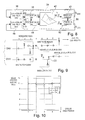
- the system comprises two servo loops corresponding to each of the two delays DAV and DVV.
- Each of these loops comprises a respective dedicated controller 36, 46, in particular a type of controller PlD (non-limiting type), associated with the error generation block 34.
- the servo control loop of the DAV comprises a PID controller 36 receiving as input an error signal E z specific to the DAV and outputting a control signal from DAV applied to a modulator circuit 38 allowing, as explained above with reference to the Figure 6 , to modulate in a controlled manner the value of the DAV around the optimal value sought.
- Block 40 illustrates the overall response to a variation of the DAV of the system comprising (cf. Figure 1 ) the CRT generator 10, the heart, the hemodynamic sensor 18 and the measurement acquisition circuit 20.
- This block 40 which therefore incorporates the function represented by the hemodynamic surface 30, gives a hemodynamic signal value Z which is demodulated by the block 42, to give the error signal E z applied to the input of the PID controller 36.
- the servo control loop of the DVV comprises a controller PlD 46 receiving as input an error signal E z specific to the DVV and outputting a DVV control signal applied to a modulator circuit 48 allowing, as discussed above with reference to the Figures 6 and 7 , to modulate in a controlled way the value of the DVV around the optimal value sought.
- the block 40 gives a hemodynamic signal value Z which is demodulated by the block 52, to give the error signal E z applied to the input of the PID controller 46.
- This interaction can result in particular from a specific sequencing of the modulation / demodulation cycles of the DAV and the DVV, respectively.
- the error signal E is available after demodulation of the values Z 1 , Z 2 and Z 3 , corresponding to the respective successive values.
- the PID controller 36 (or 46), which operates sequentially, updates the delay that it controls after multiplying this error signal by a gain and integration.
- the corresponding PID controller 36 waits for three cardiac cycles to receive an error signal. It then updates the output-controlled AVD, and remains inactive for the next three cardiac cycles, during which the DVV 46's PID controller takes over, and so on, the alternate operation of the two PID controllers 36 and 46 to ensure the convergence and the simultaneous monitoring of the two optimal delays DAV oPt and DVV oPt .
- cycles # 1 through # 3 the AVD is modulated and the DVV is held at its current value (inhibition of DVV modulation).
- an error signal C1 is calculated for the AVD. This signal C1 is applied to the input of the PID controller 36 dedicated to the DAV, and a new value of the DAV is thus determined, obtained at the output of this controller.
- the DVV is then modulated during cycles # 4 through # 6, keeping the value of the DAV just calculated (that is, the modulation of AVD inhibited during these three cycles) unchanged.
- a DVV C2 error signal is calculated and applied to the dedicated DVV PID controller 46, outputting a new value of the DVV applied to the device (cycle # 7).
- cycle 8 the process just described is reiterated by applying a DAV modulation, and so on, cycles 7, 8 and 9 corresponding to cycles 1, 2 and 3 of the iteration previous.
- a complete system adaptation cycle to new DAV / DVV values requires at least six cardiac cycles.
- k be the index of time for a PID controller (the controller 36 for the DAV or the controller 46 for the DVV).
- An adaptation cycle of the slave system corresponds to the transition from k to k +1, that is to say to a duration of at least six cardiac cycles.
- E k s ⁇ X Opt - X k s being the sensitivity of each controller, a value which depends on the modulation step ⁇ as well as the shape of the hemodynamic function.
- This condition can be expressed as: 0 ⁇ ⁇ ⁇ 2 ⁇ 0 ⁇ boy Wut ⁇ 2 s
- the gain of the loop thus depends on the sensitivity of the error generator block.
- the value of the sensitivity s is not known. It can however be estimated for a given patient and a given sensor, at least once, for example at the time of implantation of the sensor. In any case, it is nevertheless preferable to choose a gain less than 1 / s, to avoid oscillations and leave a margin of stability if the sensitivity increases over time.
- sign (E k ), in which sign represents the sign function (equal to 1 if E k is positive, and -1 otherwise).
- This variant has the advantage of being very robust, but on the other hand has the disadvantage of constantly oscillating around the optimum time.
- the implementation of the invention is not limited to the case where the error signal is obtained by a modulation / demodulation technique.
Landscapes
- Health & Medical Sciences (AREA)
- Cardiology (AREA)
- Heart & Thoracic Surgery (AREA)
- Life Sciences & Earth Sciences (AREA)
- Engineering & Computer Science (AREA)
- Biomedical Technology (AREA)
- Nuclear Medicine, Radiotherapy & Molecular Imaging (AREA)
- Radiology & Medical Imaging (AREA)
- Animal Behavior & Ethology (AREA)
- General Health & Medical Sciences (AREA)
- Public Health (AREA)
- Veterinary Medicine (AREA)
- Biophysics (AREA)
- Physiology (AREA)
- Hospice & Palliative Care (AREA)
- Hematology (AREA)
- Electrotherapy Devices (AREA)
Applications Claiming Priority (1)
| Application Number | Priority Date | Filing Date | Title |
|---|---|---|---|
| FR1050876 | 2010-02-09 |
Publications (2)
| Publication Number | Publication Date |
|---|---|
| EP2353641A1 true EP2353641A1 (de) | 2011-08-10 |
| EP2353641B1 EP2353641B1 (de) | 2013-01-23 |
Family
ID=42269637
Family Applications (1)
| Application Number | Title | Priority Date | Filing Date |
|---|---|---|---|
| EP10192940A Active EP2353641B1 (de) | 2010-02-09 | 2010-11-29 | Implantierbare aktive medizinische Vorrichtung zur Resynchronisation des Herzens mit automatischer Echtzeit-Optimierung der interventrikulären und atrioventrikulären Verzögerungen |
Country Status (2)
| Country | Link |
|---|---|
| US (1) | US8359096B2 (de) |
| EP (1) | EP2353641B1 (de) |
Families Citing this family (3)
| Publication number | Priority date | Publication date | Assignee | Title |
|---|---|---|---|---|
| EP3136959A4 (de) * | 2014-04-29 | 2017-12-13 | The Regents of the University of California | Bioimpedanzmessverfahren mit bi-phasischer stromstimuluserregung für einen implantierbaren stimulator |
| US10780279B2 (en) * | 2016-02-26 | 2020-09-22 | Medtronic, Inc. | Methods and systems of optimizing right ventricular only pacing for patients with respect to an atrial event and left ventricular event |
| EP3718598B1 (de) * | 2019-04-01 | 2024-07-31 | BIOTRONIK SE & Co. KG | Av-synchronität mit einem ventrikulären leitungslosen herzschrittmacher mit variierenden ventrikulären massen |
Citations (18)
| Publication number | Priority date | Publication date | Assignee | Title |
|---|---|---|---|---|
| EP0515319A2 (de) | 1991-05-21 | 1992-11-25 | SORIN BIOMEDICA CARDIO S.p.A. | Taktempfindlicher Herzschrittmacher |
| EP0655260A2 (de) | 1993-10-05 | 1995-05-31 | SORIN BIOMEDICA CARDIO S.p.A. | Vorrichtung und Verfahren zur Bestimmung vom Herzmuskelfunktionszustand |
| EP1108446A1 (de) | 1999-12-17 | 2001-06-20 | ELA MEDICAL (Société anonyme) | Implantierbare aktive Vorrichtung des Typs multisite mit Mitteln zum Resynchronisieren der Ventrikeln |
| EP1116497A1 (de) | 2000-01-14 | 2001-07-18 | Ela Medical | Aktive implantierbare medizinische Vorrichtung, insbesondere Herzstimulator, Defibrillator und/oder Multisite-Vorrichtung mit Mitteln zur Messung der transvalvularen Impedanz |
| EP1138346A1 (de) | 2000-03-14 | 2001-10-04 | Ela Medical | Aktive implantierbare medizinische Vorrichtung mit Mitteln zur Messung der transseptalen Bioimpedanz |
| US6522923B1 (en) * | 2001-02-09 | 2003-02-18 | Pacesetter, Inc. | Methods, systems and devices for optimizing cardiac pacing parameters using evolutionary algorithms |
| US20040078058A1 (en) * | 2002-07-22 | 2004-04-22 | Nils Holmstrom | Heart stimulator with stimulation controlled by analysis of an average impedance morphology curve |
| US6792310B1 (en) * | 2001-01-12 | 2004-09-14 | Pacesetter, Inc. | Methods, systems and devices for optimizing cardiac pacing parameters |
| US20050131469A1 (en) * | 2003-12-16 | 2005-06-16 | Leonard Bloom | Hemodynamic optimization system for biventricular implants |
| WO2006090397A2 (en) | 2005-02-28 | 2006-08-31 | A.I. Medical Semiconductor | Adaptive cardiac resynchronization therapy and vagal stimulation |
| WO2006126185A2 (en) | 2005-05-27 | 2006-11-30 | A.I. Medical Semiconductor | Ventricle pacing during atrial fibrillation episodes |
| EP1741387A1 (de) | 2005-07-05 | 2007-01-10 | Ela Medical | Vorrichtung zur nicht invasiven Detektion von Schlafapnoe oder Hypopneen |
| US20070066905A1 (en) * | 2005-09-21 | 2007-03-22 | Cardiac Pacemakers, Inc. | Method and apparatus for controlling cardiac resynchronization therapy using cardiac impedance |
| WO2008010220A2 (en) | 2006-07-17 | 2008-01-24 | A. I. Medical Semiconductor | Intelligent control system for adaptive cardiac resynchronization therapy device |
| US20080114410A1 (en) | 2005-05-25 | 2008-05-15 | Cardiac Pacemakers, Inc. | Closed loop impedance-based cardiac resynchronization therapy systems, devices, and methods |
| WO2008133552A1 (en) * | 2007-04-27 | 2008-11-06 | St. Jude Medical Ab | Implantable medical device and method for monitoring valve movements of a heart |
| US20090105777A1 (en) * | 2007-10-12 | 2009-04-23 | Yanting Dong | Method and apparatus to trend and optimize an implantable medical device using a patient management system |
| US7558627B1 (en) * | 2003-09-29 | 2009-07-07 | Pacesetter, Inc. | System and method for rapid optimization of control parameters of an implantable cardiac stimulation device |
-
2010
- 2010-11-29 EP EP10192940A patent/EP2353641B1/de active Active
-
2011
- 2011-02-09 US US13/024,205 patent/US8359096B2/en active Active
Patent Citations (18)
| Publication number | Priority date | Publication date | Assignee | Title |
|---|---|---|---|---|
| EP0515319A2 (de) | 1991-05-21 | 1992-11-25 | SORIN BIOMEDICA CARDIO S.p.A. | Taktempfindlicher Herzschrittmacher |
| EP0655260A2 (de) | 1993-10-05 | 1995-05-31 | SORIN BIOMEDICA CARDIO S.p.A. | Vorrichtung und Verfahren zur Bestimmung vom Herzmuskelfunktionszustand |
| EP1108446A1 (de) | 1999-12-17 | 2001-06-20 | ELA MEDICAL (Société anonyme) | Implantierbare aktive Vorrichtung des Typs multisite mit Mitteln zum Resynchronisieren der Ventrikeln |
| EP1116497A1 (de) | 2000-01-14 | 2001-07-18 | Ela Medical | Aktive implantierbare medizinische Vorrichtung, insbesondere Herzstimulator, Defibrillator und/oder Multisite-Vorrichtung mit Mitteln zur Messung der transvalvularen Impedanz |
| EP1138346A1 (de) | 2000-03-14 | 2001-10-04 | Ela Medical | Aktive implantierbare medizinische Vorrichtung mit Mitteln zur Messung der transseptalen Bioimpedanz |
| US6792310B1 (en) * | 2001-01-12 | 2004-09-14 | Pacesetter, Inc. | Methods, systems and devices for optimizing cardiac pacing parameters |
| US6522923B1 (en) * | 2001-02-09 | 2003-02-18 | Pacesetter, Inc. | Methods, systems and devices for optimizing cardiac pacing parameters using evolutionary algorithms |
| US20040078058A1 (en) * | 2002-07-22 | 2004-04-22 | Nils Holmstrom | Heart stimulator with stimulation controlled by analysis of an average impedance morphology curve |
| US7558627B1 (en) * | 2003-09-29 | 2009-07-07 | Pacesetter, Inc. | System and method for rapid optimization of control parameters of an implantable cardiac stimulation device |
| US20050131469A1 (en) * | 2003-12-16 | 2005-06-16 | Leonard Bloom | Hemodynamic optimization system for biventricular implants |
| WO2006090397A2 (en) | 2005-02-28 | 2006-08-31 | A.I. Medical Semiconductor | Adaptive cardiac resynchronization therapy and vagal stimulation |
| US20080114410A1 (en) | 2005-05-25 | 2008-05-15 | Cardiac Pacemakers, Inc. | Closed loop impedance-based cardiac resynchronization therapy systems, devices, and methods |
| WO2006126185A2 (en) | 2005-05-27 | 2006-11-30 | A.I. Medical Semiconductor | Ventricle pacing during atrial fibrillation episodes |
| EP1741387A1 (de) | 2005-07-05 | 2007-01-10 | Ela Medical | Vorrichtung zur nicht invasiven Detektion von Schlafapnoe oder Hypopneen |
| US20070066905A1 (en) * | 2005-09-21 | 2007-03-22 | Cardiac Pacemakers, Inc. | Method and apparatus for controlling cardiac resynchronization therapy using cardiac impedance |
| WO2008010220A2 (en) | 2006-07-17 | 2008-01-24 | A. I. Medical Semiconductor | Intelligent control system for adaptive cardiac resynchronization therapy device |
| WO2008133552A1 (en) * | 2007-04-27 | 2008-11-06 | St. Jude Medical Ab | Implantable medical device and method for monitoring valve movements of a heart |
| US20090105777A1 (en) * | 2007-10-12 | 2009-04-23 | Yanting Dong | Method and apparatus to trend and optimize an implantable medical device using a patient management system |
Non-Patent Citations (2)
| Title |
|---|
| DAVID TAMBORERO ET AL.: "Optimization of the Interventricular Delay in Cardiac Resynchronization Therapy Using the QRS Width", AMERICAN JOURNAL OF CARDIOLOGY, vol. 104, no. 10, 15 November 2009 (2009-11-15), pages 1407 - 1412 |
| JM DUPUIS ET AL.: "Programming Optimal Atrioventricular Delay in Dual Chamber Pacing Using Peak Endocardial Acceleration : Comparison with a Standard Echocardiographic Procedure", PACE, vol. 26, 2003, pages 210 - 213 |
Also Published As
| Publication number | Publication date |
|---|---|
| US8359096B2 (en) | 2013-01-22 |
| EP2353641B1 (de) | 2013-01-23 |
| US20110196443A1 (en) | 2011-08-11 |
Similar Documents
| Publication | Publication Date | Title |
|---|---|---|
| EP2070562B1 (de) | Medizinische Vorrichtung zur Bestimmung des Herzzustands eines Patienten, dem ein aktives Implantat zur biventrikulären Stimulation eingesetzt wurde | |
| EP2357020B1 (de) | Aktive medizinische Vorrichtung vom Typ Herzschrittmacher, Defibrillator und/oder Resynchronisator mit automatischer Optimierung der atrioventrikulären Verzögerung | |
| EP2092885B1 (de) | Analysevorrichtung eines endokardialen Beschleunigungssignals | |
| EP2263747B1 (de) | Implantierbare Herzprothese mit Mittel zur Analyse der Patiententoleranz bezüglich der Stimulationsart die spontane Atrio-Ventrukuläre Leitung bevorzugend | |
| EP3113033B1 (de) | Stimulationsbehandlungssystem, insbesondere für den vagusnerv durch anwendung eines zustandsübergangsmodells | |
| EP2189182B1 (de) | Aktives medizinisches Implantat, das mit Testmitteln zur aurikulären Datenerfassung ausgestattet ist | |
| EP2737925B1 (de) | Aktive implantierbare Herzprothese mit Erfassung der aurikularen mechanischen Aktivität | |
| EP0862927B1 (de) | Multi-Ort Herzschrittmacher zur Behandlung von Herzinsuffizienzen mit Reizimpulsen | |
| EP1617901A2 (de) | Herzschrittmacher für optimale intra-ventikulare resynchronisation | |
| EP1736203B1 (de) | Implantierbares medizinisches Gerät zur biventrikulären Stimulation und zur automatischen Optimierung der Anregungskonfiguration | |
| EP2311524B1 (de) | Implantierbarer medizinischer Herzschrittmacher und Verfahren zur Optimierung des Implantatortes für interventrikuläre und atrioventrikuläre Intervalle | |
| EP3111991B1 (de) | Stimulationsbehandlungssystem, insbesondere für die stimulation des vagusnervs durch anwendung eines zustandsübergangsmodells, das sich automatisch an die physischen und physiologischen niveaus anpasst | |
| FR2803759A1 (fr) | Dispositif medical implantable actif, notamment stimulateur cardiaque, defibrillateur et/ou dispositif multisite comportant des moyens de mesure d'impedance transvalvulaire | |
| EP2499971A1 (de) | Adaptative Datenverarbeitungsvorrichtung eines endokardialen Beschleunigungssignals | |
| EP2374503B1 (de) | Aktive implantierbare medizinische Vorrichtung für Vagusnervstimulation mit Optimisierung der Ventrikelfüllung | |
| EP2471575A1 (de) | Implantierbare aktive medizinische Vorrichtung zur Aurikelstimulation für die Behandlung von diastolischer Herzinsuffizienz | |
| EP2353641B1 (de) | Implantierbare aktive medizinische Vorrichtung zur Resynchronisation des Herzens mit automatischer Echtzeit-Optimierung der interventrikulären und atrioventrikulären Verzögerungen | |
| EP2508227B1 (de) | Implantierbare Herzprothese zur Resynchronisation des Herzens durch biventrikuläre Stimulation, die Mittel zur inversen Herzrekonfiguration umfasst | |
| EP1405654B1 (de) | Aktives implantierbares medizinisches Gerät, wie Herzschrittmacher, Defibrillatoren, Kardiovertierer und/oder Multisitevorrichtungen, mit Mitteln zur Feststellung der durchschnittlichen hemodynamischen Kennzahl | |
| EP3111990B1 (de) | Stimulationsbehandlungssystem, insbesondere für die stimulation des vagusnervs durch anwendung eines zustandsübergangsmodells mit vorausgehendem lernen | |
| EP2712549A1 (de) | Vorrichtung zur Bewertung der zeitlichen ventrikulären Desynchronisierung | |
| EP2206531A1 (de) | Aktive medizinische Vorrichtung vom Typ implantierbare Herzprothese für die Behandlung von Herzinsuffizienz durch kontrollierte Anpassung der atrioventrikulären und intraventrikulären Durchblutungszeiten | |
| EP3081257B1 (de) | Aktive implantierbare medizinische vorrichtung zur herzstimulation, die detektionsmittel für remodellierungserscheinungen oder inversen remodellierungserscheinungen des patienten umfasst | |
| EP2803385A1 (de) | Implantierbares CRT-Gerät zur Stimulation beider Ventrikel und zur Erkennung von Erfassungsverlusten und anodischen Stimulationen | |
| EP2684515B1 (de) | Aktive medizinische Vorrichtung, die Mittel zur Überwachung des Zustands eines Patienten mit Herzinsuffizienzrisiko umfasst |
Legal Events
| Date | Code | Title | Description |
|---|---|---|---|
| PUAI | Public reference made under article 153(3) epc to a published international application that has entered the european phase |
Free format text: ORIGINAL CODE: 0009012 |
|
| AK | Designated contracting states |
Kind code of ref document: A1 Designated state(s): AL AT BE BG CH CY CZ DE DK EE ES FI FR GB GR HR HU IE IS IT LI LT LU LV MC MK MT NL NO PL PT RO RS SE SI SK SM TR |
|
| AX | Request for extension of the european patent |
Extension state: BA ME |
|
| 17P | Request for examination filed |
Effective date: 20120202 |
|
| 17Q | First examination report despatched |
Effective date: 20120319 |
|
| RIC1 | Information provided on ipc code assigned before grant |
Ipc: A61N 1/362 20060101AFI20120705BHEP Ipc: G05B 11/01 20060101ALI20120705BHEP Ipc: A61N 1/368 20060101ALN20120705BHEP Ipc: G05B 13/02 20060101ALI20120705BHEP Ipc: A61N 1/365 20060101ALI20120705BHEP Ipc: G05B 6/02 20060101ALI20120705BHEP |
|
| GRAP | Despatch of communication of intention to grant a patent |
Free format text: ORIGINAL CODE: EPIDOSNIGR1 |
|
| RIC1 | Information provided on ipc code assigned before grant |
Ipc: G05B 13/02 20060101ALI20120723BHEP Ipc: A61N 1/365 20060101ALI20120723BHEP Ipc: A61N 1/362 20060101AFI20120723BHEP Ipc: G05B 6/02 20060101ALI20120723BHEP Ipc: A61N 1/368 20060101ALN20120723BHEP Ipc: G05B 11/01 20060101ALI20120723BHEP |
|
| GRAS | Grant fee paid |
Free format text: ORIGINAL CODE: EPIDOSNIGR3 |
|
| GRAA | (expected) grant |
Free format text: ORIGINAL CODE: 0009210 |
|
| AK | Designated contracting states |
Kind code of ref document: B1 Designated state(s): AL AT BE BG CH CY CZ DE DK EE ES FI FR GB GR HR HU IE IS IT LI LT LU LV MC MK MT NL NO PL PT RO RS SE SI SK SM TR |
|
| REG | Reference to a national code |
Ref country code: GB Ref legal event code: FG4D Free format text: NOT ENGLISH |
|
| REG | Reference to a national code |
Ref country code: CH Ref legal event code: EP |
|
| REG | Reference to a national code |
Ref country code: AT Ref legal event code: REF Ref document number: 594632 Country of ref document: AT Kind code of ref document: T Effective date: 20130215 Ref country code: CH Ref legal event code: EP |
|
| REG | Reference to a national code |
Ref country code: IE Ref legal event code: FG4D Free format text: LANGUAGE OF EP DOCUMENT: FRENCH |
|
| REG | Reference to a national code |
Ref country code: DE Ref legal event code: R096 Ref document number: 602010004800 Country of ref document: DE Effective date: 20130321 |
|
| REG | Reference to a national code |
Ref country code: AT Ref legal event code: MK05 Ref document number: 594632 Country of ref document: AT Kind code of ref document: T Effective date: 20130123 |
|
| REG | Reference to a national code |
Ref country code: LT Ref legal event code: MG4D |
|
| REG | Reference to a national code |
Ref country code: NL Ref legal event code: VDEP Effective date: 20130123 |
|
| PG25 | Lapsed in a contracting state [announced via postgrant information from national office to epo] |
Ref country code: AT Free format text: LAPSE BECAUSE OF FAILURE TO SUBMIT A TRANSLATION OF THE DESCRIPTION OR TO PAY THE FEE WITHIN THE PRESCRIBED TIME-LIMIT Effective date: 20130123 Ref country code: IS Free format text: LAPSE BECAUSE OF FAILURE TO SUBMIT A TRANSLATION OF THE DESCRIPTION OR TO PAY THE FEE WITHIN THE PRESCRIBED TIME-LIMIT Effective date: 20130523 Ref country code: NO Free format text: LAPSE BECAUSE OF FAILURE TO SUBMIT A TRANSLATION OF THE DESCRIPTION OR TO PAY THE FEE WITHIN THE PRESCRIBED TIME-LIMIT Effective date: 20130423 Ref country code: BG Free format text: LAPSE BECAUSE OF FAILURE TO SUBMIT A TRANSLATION OF THE DESCRIPTION OR TO PAY THE FEE WITHIN THE PRESCRIBED TIME-LIMIT Effective date: 20130423 Ref country code: LT Free format text: LAPSE BECAUSE OF FAILURE TO SUBMIT A TRANSLATION OF THE DESCRIPTION OR TO PAY THE FEE WITHIN THE PRESCRIBED TIME-LIMIT Effective date: 20130123 Ref country code: SE Free format text: LAPSE BECAUSE OF FAILURE TO SUBMIT A TRANSLATION OF THE DESCRIPTION OR TO PAY THE FEE WITHIN THE PRESCRIBED TIME-LIMIT Effective date: 20130123 Ref country code: ES Free format text: LAPSE BECAUSE OF FAILURE TO SUBMIT A TRANSLATION OF THE DESCRIPTION OR TO PAY THE FEE WITHIN THE PRESCRIBED TIME-LIMIT Effective date: 20130504 |
|
| PG25 | Lapsed in a contracting state [announced via postgrant information from national office to epo] |
Ref country code: FI Free format text: LAPSE BECAUSE OF FAILURE TO SUBMIT A TRANSLATION OF THE DESCRIPTION OR TO PAY THE FEE WITHIN THE PRESCRIBED TIME-LIMIT Effective date: 20130123 Ref country code: SI Free format text: LAPSE BECAUSE OF FAILURE TO SUBMIT A TRANSLATION OF THE DESCRIPTION OR TO PAY THE FEE WITHIN THE PRESCRIBED TIME-LIMIT Effective date: 20130123 Ref country code: PT Free format text: LAPSE BECAUSE OF FAILURE TO SUBMIT A TRANSLATION OF THE DESCRIPTION OR TO PAY THE FEE WITHIN THE PRESCRIBED TIME-LIMIT Effective date: 20130523 Ref country code: PL Free format text: LAPSE BECAUSE OF FAILURE TO SUBMIT A TRANSLATION OF THE DESCRIPTION OR TO PAY THE FEE WITHIN THE PRESCRIBED TIME-LIMIT Effective date: 20130123 Ref country code: GR Free format text: LAPSE BECAUSE OF FAILURE TO SUBMIT A TRANSLATION OF THE DESCRIPTION OR TO PAY THE FEE WITHIN THE PRESCRIBED TIME-LIMIT Effective date: 20130424 Ref country code: LV Free format text: LAPSE BECAUSE OF FAILURE TO SUBMIT A TRANSLATION OF THE DESCRIPTION OR TO PAY THE FEE WITHIN THE PRESCRIBED TIME-LIMIT Effective date: 20130123 Ref country code: NL Free format text: LAPSE BECAUSE OF FAILURE TO SUBMIT A TRANSLATION OF THE DESCRIPTION OR TO PAY THE FEE WITHIN THE PRESCRIBED TIME-LIMIT Effective date: 20130123 |
|
| PG25 | Lapsed in a contracting state [announced via postgrant information from national office to epo] |
Ref country code: HR Free format text: LAPSE BECAUSE OF FAILURE TO SUBMIT A TRANSLATION OF THE DESCRIPTION OR TO PAY THE FEE WITHIN THE PRESCRIBED TIME-LIMIT Effective date: 20130123 Ref country code: RS Free format text: LAPSE BECAUSE OF FAILURE TO SUBMIT A TRANSLATION OF THE DESCRIPTION OR TO PAY THE FEE WITHIN THE PRESCRIBED TIME-LIMIT Effective date: 20130123 |
|
| PG25 | Lapsed in a contracting state [announced via postgrant information from national office to epo] |
Ref country code: RO Free format text: LAPSE BECAUSE OF FAILURE TO SUBMIT A TRANSLATION OF THE DESCRIPTION OR TO PAY THE FEE WITHIN THE PRESCRIBED TIME-LIMIT Effective date: 20130123 Ref country code: CZ Free format text: LAPSE BECAUSE OF FAILURE TO SUBMIT A TRANSLATION OF THE DESCRIPTION OR TO PAY THE FEE WITHIN THE PRESCRIBED TIME-LIMIT Effective date: 20130123 Ref country code: SK Free format text: LAPSE BECAUSE OF FAILURE TO SUBMIT A TRANSLATION OF THE DESCRIPTION OR TO PAY THE FEE WITHIN THE PRESCRIBED TIME-LIMIT Effective date: 20130123 Ref country code: DK Free format text: LAPSE BECAUSE OF FAILURE TO SUBMIT A TRANSLATION OF THE DESCRIPTION OR TO PAY THE FEE WITHIN THE PRESCRIBED TIME-LIMIT Effective date: 20130123 Ref country code: EE Free format text: LAPSE BECAUSE OF FAILURE TO SUBMIT A TRANSLATION OF THE DESCRIPTION OR TO PAY THE FEE WITHIN THE PRESCRIBED TIME-LIMIT Effective date: 20130123 |
|
| PG25 | Lapsed in a contracting state [announced via postgrant information from national office to epo] |
Ref country code: CY Free format text: LAPSE BECAUSE OF FAILURE TO SUBMIT A TRANSLATION OF THE DESCRIPTION OR TO PAY THE FEE WITHIN THE PRESCRIBED TIME-LIMIT Effective date: 20130123 |
|
| PLBE | No opposition filed within time limit |
Free format text: ORIGINAL CODE: 0009261 |
|
| STAA | Information on the status of an ep patent application or granted ep patent |
Free format text: STATUS: NO OPPOSITION FILED WITHIN TIME LIMIT |
|
| 26N | No opposition filed |
Effective date: 20131024 |
|
| REG | Reference to a national code |
Ref country code: DE Ref legal event code: R097 Ref document number: 602010004800 Country of ref document: DE Effective date: 20131024 |
|
| BERE | Be: lapsed |
Owner name: SORIN CRM SAS Effective date: 20131130 |
|
| PG25 | Lapsed in a contracting state [announced via postgrant information from national office to epo] |
Ref country code: MC Free format text: LAPSE BECAUSE OF FAILURE TO SUBMIT A TRANSLATION OF THE DESCRIPTION OR TO PAY THE FEE WITHIN THE PRESCRIBED TIME-LIMIT Effective date: 20130123 |
|
| REG | Reference to a national code |
Ref country code: IE Ref legal event code: MM4A |
|
| PG25 | Lapsed in a contracting state [announced via postgrant information from national office to epo] |
Ref country code: BE Free format text: LAPSE BECAUSE OF NON-PAYMENT OF DUE FEES Effective date: 20131130 |
|
| PG25 | Lapsed in a contracting state [announced via postgrant information from national office to epo] |
Ref country code: IE Free format text: LAPSE BECAUSE OF NON-PAYMENT OF DUE FEES Effective date: 20131129 |
|
| PG25 | Lapsed in a contracting state [announced via postgrant information from national office to epo] |
Ref country code: SM Free format text: LAPSE BECAUSE OF FAILURE TO SUBMIT A TRANSLATION OF THE DESCRIPTION OR TO PAY THE FEE WITHIN THE PRESCRIBED TIME-LIMIT Effective date: 20130123 |
|
| PG25 | Lapsed in a contracting state [announced via postgrant information from national office to epo] |
Ref country code: TR Free format text: LAPSE BECAUSE OF FAILURE TO SUBMIT A TRANSLATION OF THE DESCRIPTION OR TO PAY THE FEE WITHIN THE PRESCRIBED TIME-LIMIT Effective date: 20130123 |
|
| REG | Reference to a national code |
Ref country code: CH Ref legal event code: PL |
|
| PG25 | Lapsed in a contracting state [announced via postgrant information from national office to epo] |
Ref country code: LU Free format text: LAPSE BECAUSE OF NON-PAYMENT OF DUE FEES Effective date: 20131129 Ref country code: HU Free format text: LAPSE BECAUSE OF FAILURE TO SUBMIT A TRANSLATION OF THE DESCRIPTION OR TO PAY THE FEE WITHIN THE PRESCRIBED TIME-LIMIT; INVALID AB INITIO Effective date: 20101129 Ref country code: CH Free format text: LAPSE BECAUSE OF NON-PAYMENT OF DUE FEES Effective date: 20141130 Ref country code: MK Free format text: LAPSE BECAUSE OF FAILURE TO SUBMIT A TRANSLATION OF THE DESCRIPTION OR TO PAY THE FEE WITHIN THE PRESCRIBED TIME-LIMIT Effective date: 20130123 Ref country code: LI Free format text: LAPSE BECAUSE OF NON-PAYMENT OF DUE FEES Effective date: 20141130 |
|
| PG25 | Lapsed in a contracting state [announced via postgrant information from national office to epo] |
Ref country code: MT Free format text: LAPSE BECAUSE OF FAILURE TO SUBMIT A TRANSLATION OF THE DESCRIPTION OR TO PAY THE FEE WITHIN THE PRESCRIBED TIME-LIMIT Effective date: 20130123 |
|
| REG | Reference to a national code |
Ref country code: FR Ref legal event code: PLFP Year of fee payment: 6 |
|
| REG | Reference to a national code |
Ref country code: FR Ref legal event code: PLFP Year of fee payment: 7 |
|
| REG | Reference to a national code |
Ref country code: FR Ref legal event code: PLFP Year of fee payment: 8 |
|
| REG | Reference to a national code |
Ref country code: FR Ref legal event code: PLFP Year of fee payment: 9 |
|
| PG25 | Lapsed in a contracting state [announced via postgrant information from national office to epo] |
Ref country code: AL Free format text: LAPSE BECAUSE OF FAILURE TO SUBMIT A TRANSLATION OF THE DESCRIPTION OR TO PAY THE FEE WITHIN THE PRESCRIBED TIME-LIMIT Effective date: 20130123 |
|
| P01 | Opt-out of the competence of the unified patent court (upc) registered |
Effective date: 20230714 |
|
| PGFP | Annual fee paid to national office [announced via postgrant information from national office to epo] |
Ref country code: DE Payment date: 20241108 Year of fee payment: 15 |
|
| PGFP | Annual fee paid to national office [announced via postgrant information from national office to epo] |
Ref country code: GB Payment date: 20241122 Year of fee payment: 15 |
|
| PGFP | Annual fee paid to national office [announced via postgrant information from national office to epo] |
Ref country code: FR Payment date: 20241120 Year of fee payment: 15 |
|
| PGFP | Annual fee paid to national office [announced via postgrant information from national office to epo] |
Ref country code: IT Payment date: 20241107 Year of fee payment: 15 |
|
| REG | Reference to a national code |
Ref country code: DE Ref legal event code: R082 Ref document number: 602010004800 Country of ref document: DE Representative=s name: GULDE & PARTNER PATENT- UND RECHTSANWALTSKANZL, DE |