EP2354090A2 - Verfahren und Vorrichtung zur Herstellung von Trichlorsilan - Google Patents
Verfahren und Vorrichtung zur Herstellung von Trichlorsilan Download PDFInfo
- Publication number
- EP2354090A2 EP2354090A2 EP11164834A EP11164834A EP2354090A2 EP 2354090 A2 EP2354090 A2 EP 2354090A2 EP 11164834 A EP11164834 A EP 11164834A EP 11164834 A EP11164834 A EP 11164834A EP 2354090 A2 EP2354090 A2 EP 2354090A2
- Authority
- EP
- European Patent Office
- Prior art keywords
- hydrogen chloride
- containing compound
- decomposition furnace
- trichlorosilane
- boiling
- Prior art date
- Legal status (The legal status is an assumption and is not a legal conclusion. Google has not performed a legal analysis and makes no representation as to the accuracy of the status listed.)
- Granted
Links
Images


Classifications
-
- B—PERFORMING OPERATIONS; TRANSPORTING
- B01—PHYSICAL OR CHEMICAL PROCESSES OR APPARATUS IN GENERAL
- B01J—CHEMICAL OR PHYSICAL PROCESSES, e.g. CATALYSIS OR COLLOID CHEMISTRY; THEIR RELEVANT APPARATUS
- B01J19/00—Chemical, physical or physico-chemical processes in general; Their relevant apparatus
- B01J19/24—Stationary reactors without moving elements inside
-
- C—CHEMISTRY; METALLURGY
- C01—INORGANIC CHEMISTRY
- C01B—NON-METALLIC ELEMENTS; COMPOUNDS THEREOF; METALLOIDS OR COMPOUNDS THEREOF NOT COVERED BY SUBCLASS C01C
- C01B33/00—Silicon; Compounds thereof
- C01B33/08—Compounds containing halogen
- C01B33/107—Halogenated silanes
-
- B—PERFORMING OPERATIONS; TRANSPORTING
- B01—PHYSICAL OR CHEMICAL PROCESSES OR APPARATUS IN GENERAL
- B01J—CHEMICAL OR PHYSICAL PROCESSES, e.g. CATALYSIS OR COLLOID CHEMISTRY; THEIR RELEVANT APPARATUS
- B01J19/00—Chemical, physical or physico-chemical processes in general; Their relevant apparatus
- B01J19/0053—Details of the reactor
-
- C—CHEMISTRY; METALLURGY
- C01—INORGANIC CHEMISTRY
- C01B—NON-METALLIC ELEMENTS; COMPOUNDS THEREOF; METALLOIDS OR COMPOUNDS THEREOF NOT COVERED BY SUBCLASS C01C
- C01B33/00—Silicon; Compounds thereof
- C01B33/08—Compounds containing halogen
- C01B33/107—Halogenated silanes
- C01B33/1071—Tetrachloride, trichlorosilane or silicochloroform, dichlorosilane, monochlorosilane or mixtures thereof
- C01B33/10742—Tetrachloride, trichlorosilane or silicochloroform, dichlorosilane, monochlorosilane or mixtures thereof prepared by hydrochlorination of silicon or of a silicon-containing material
- C01B33/10757—Tetrachloride, trichlorosilane or silicochloroform, dichlorosilane, monochlorosilane or mixtures thereof prepared by hydrochlorination of silicon or of a silicon-containing material with the preferential formation of trichlorosilane
-
- B—PERFORMING OPERATIONS; TRANSPORTING
- B01—PHYSICAL OR CHEMICAL PROCESSES OR APPARATUS IN GENERAL
- B01J—CHEMICAL OR PHYSICAL PROCESSES, e.g. CATALYSIS OR COLLOID CHEMISTRY; THEIR RELEVANT APPARATUS
- B01J2219/00—Chemical, physical or physico-chemical processes in general; Their relevant apparatus
- B01J2219/00049—Controlling or regulating processes
- B01J2219/00051—Controlling the temperature
- B01J2219/00054—Controlling or regulating the heat exchange system
- B01J2219/00056—Controlling or regulating the heat exchange system involving measured parameters
- B01J2219/00058—Temperature measurement
- B01J2219/00063—Temperature measurement of the reactants
-
- B—PERFORMING OPERATIONS; TRANSPORTING
- B01—PHYSICAL OR CHEMICAL PROCESSES OR APPARATUS IN GENERAL
- B01J—CHEMICAL OR PHYSICAL PROCESSES, e.g. CATALYSIS OR COLLOID CHEMISTRY; THEIR RELEVANT APPARATUS
- B01J2219/00—Chemical, physical or physico-chemical processes in general; Their relevant apparatus
- B01J2219/00049—Controlling or regulating processes
- B01J2219/00051—Controlling the temperature
- B01J2219/00132—Controlling the temperature using electric heating or cooling elements
- B01J2219/00135—Electric resistance heaters
-
- B—PERFORMING OPERATIONS; TRANSPORTING
- B01—PHYSICAL OR CHEMICAL PROCESSES OR APPARATUS IN GENERAL
- B01J—CHEMICAL OR PHYSICAL PROCESSES, e.g. CATALYSIS OR COLLOID CHEMISTRY; THEIR RELEVANT APPARATUS
- B01J2219/00—Chemical, physical or physico-chemical processes in general; Their relevant apparatus
- B01J2219/00049—Controlling or regulating processes
- B01J2219/00051—Controlling the temperature
- B01J2219/00159—Controlling the temperature controlling multiple zones along the direction of flow, e.g. pre-heating and after-cooling
-
- Y—GENERAL TAGGING OF NEW TECHNOLOGICAL DEVELOPMENTS; GENERAL TAGGING OF CROSS-SECTIONAL TECHNOLOGIES SPANNING OVER SEVERAL SECTIONS OF THE IPC; TECHNICAL SUBJECTS COVERED BY FORMER USPC CROSS-REFERENCE ART COLLECTIONS [XRACs] AND DIGESTS
- Y02—TECHNOLOGIES OR APPLICATIONS FOR MITIGATION OR ADAPTATION AGAINST CLIMATE CHANGE
- Y02P—CLIMATE CHANGE MITIGATION TECHNOLOGIES IN THE PRODUCTION OR PROCESSING OF GOODS
- Y02P20/00—Technologies relating to chemical industry
- Y02P20/10—Process efficiency
- Y02P20/129—Energy recovery, e.g. by cogeneration, H2recovery or pressure recovery turbines
Definitions
- the present invention relates to a method and an apparatus for manufacturing trichlorosilane by decomposing compounds (hereinbelow, referred to as "polymers") containing high-boiling chlorosilane, which are generated in a polycrystalline silicon manufacturing process.
- the present invention relates to a method and an apparatus for manufacturing trichlorosilane by decomposing polymers that have been separated in a chlorination step or polymers that have been separated from an exhaust gas of a polycrystalline silicon manufacturing process.
- the high-purity polycrystalline silicon that can be used as a semiconductor material is mainly manufactured by the Siemens process in which, for example, trichlorosilane (SiHCl 3 ; abbreviated "TCS”) and hydrogen are used as raw materials, a gas mixture thereof is introduced into a reactor and brought into contact with heated silicon rods, and silicon is deposited on the surfaces of the silicon rods due to the hydrogen reduction or thermal decomposition of the trichlorosilane at a high temperature.
- TCS trichlorosilane
- hydrogen hydrogen
- the high purity trichlorosilane to be introduced into the reactor for example, is manufactured by introducing metallurgical grade silicon and hydrogen chloride into a fluidized-bed chlorination furnace to react them, chlorinating the silicon to produce crude TCS (chlorination step), and purifying the crude TCS by distillation into high purity TCS.
- the reactor exhaust gas includes, in addition to unreacted trichlorosilane, hydrogen, and hydrogen chloride, by-products such as silicon tetrachloride (STC) and chlorosilanes including, for example, tetrachlorodisilane (Si 2 H 2 Cl 4 ) and hexachlorodisilane (Si 2 Cl 6 ).
- STC silicon tetrachloride
- chlorosilanes including, for example, tetrachlorodisilane (Si 2 H 2 Cl 4 ) and hexachlorodisilane (Si 2 Cl 6 ).
- the chlorosilanes have boiling point higher than that of silicon tetrachloride, and they are referred to herein as "high boiling chlorosilanes".
- the gas produced in the chlorination reactor includes, in addition to trichlorosilane and unreacted hydrogen chloride, by-products such as silicon tetrachloride and
- Patent Document 2 Japanese Unexamined Patent Application, First Publication No. H01-188414 .
- US 2004/0131528 A1 and US 2002/183537 A1 disclose methods for decomposing disilane by introducing disilane and hydrogen chloride into a furnace and heating the mixture thereof.
- the present invention solves the above problems in the conventional polycrystalline silicon manufacture, and provides a manufacturing technology in which polymers separated from crude TCS in the chlorination step and polymers separated from the exhaust gas in the reactor are decomposed and converted to trichlorosilane.
- the present invention relates to a method and an apparatus for manufacturing trichlorosilane that solves the problems described above based on the features recited in claims 1 and 5 and, in certain cases, in claims 2-4 and 6. It may use the following features.
- the method of the present invention is a method for manufacturing trichlorosilane by decomposing polymers, and for example, enables recovering trichlorosilane by decomposing polymers that have been separated in a polycrystalline silicon manufacturing process, enables significantly reducing the load incurred due to carrying out waste disposal by hydrolytic the polymers, increases the consumption efficiency of raw materials by recycling the recovered trichlorosilane, and enables the reduction of the polycrystalline silicon manufacturing cost.
- the manufacturing method of the present invention enables recovering trichlorosilane by decomposing at least one of a polymer that has been separated in a chlorination step in a polycrystalline silicon manufacturing process and a polymer that has been separated from an exhaust gas of a reactor.
- the recovered trichlorosilane can be recycled as a raw material for manufacturing polycrystalline silicon.
- the manufacturing apparatus of the present invention is provided with a decomposition furnace that produces trichlorosilane by heating and decomposing polymers, and because trichlorosilane is manufactured by mixing the polymers and hydrogen chloride and reacting the mixture at a predetermined temperature, it is possible to manufacture trichlorosilane by using the polymers that have been separated in the chlorination step or the polymers that have been separated from the exhaust gas of the reactor.
- the mixture is preheated while flowing through the supply pipe inside the furnace, and it is possible to react the mixture efficiently and to increase the yield of the trichlorosilane.
- the method of the present invention is a method for manufacturing trichlorosilane, wherein high-boiling chlorosilane compounds (referred to herein as "polymers"), which have been generated in a polycrystalline silicon manufacturing process, are mixed with hydrogen chloride and introduced into a decomposition furnace, the polymers and the hydrogen chloride are reacted at a temperature of 450°C or more, or preferably, of 450°C or more and 700°C or less, and the trichlorosilane is thereby manufactured.
- polymers high-boiling chlorosilane compounds
- the decomposition process includes the following reactions.
- Polymers may include other compounds such as pentachlorodisilane (Si 2 HCl 5 ) and octachlorotrisilane (Si 3 Cl 8 ). These compounds can also be decomposed by reacting with hydrogen chloride as well as the reactions (1) and (2).
- the manufacturing method of the present invention can be applied to polymers that are separated in a manufacturing process for polycrystalline silicon.
- An example of a process for polycrystalline silicon manufacture is shown in FIG. 1 .
- the illustrated manufacturing system includes a fluidized-bed chlorination furnace 10 that produces crude (unrefined) TCS by reacting a metallurgical grade silicon and hydrogen chloride; a first distillation column 11 that distils the produced chlorosilanes including the crude TCS produced by the chlorination reactor 10; an evaporator 12 that evaporates purified TCS along with hydrogen, STC, and TCS that are recovered from the downstream processes to prepare raw material gas; a reactor 13 that manufactures polycrystalline silicon from the raw material gas; and a condenser 14 that separates the chlorosilanes from the exhaust gas of the reactor 13.
- the metallurgical grade silicon and the hydrogen chloride are introduced into the fluidized-bed chlorination furnace 10, and, in a fluidized state, metallurgical grade silicon and hydrogen chloride are reacted to produce crude TCS. At this time, polymers are also generated.
- the produced chlorosilanes which includes crude TCS, by-products, and unreacted hydrogen chloride and the like, is introduced into the distillation column 11 from the fluidized-bed chlorination furnace 10, and the crude TCS is purified by distillation.
- the purified TCS is introduced into the evaporator 12 from the distillation column 11, and at the same time, the distillation residue in the distillation column 11 is separated from the column bottom.
- the distillation residue includes polymers generated in the above process and the like, and distillation residue including the polymers are fed to the polymer decomposition step 30 according to an embodiment of the present invention.
- the TCS which has been introduced from the distillation column 11, and the hydrogen, STC, and TCS, which have been recovered from the downstream steps, are introduced into the evaporator 12, and a raw material gas in which these are mixed is prepared.
- This raw material gas is introduced into the reactor 13. Inside the reactor 13, plural silicon rods are stood, these silicon rods are heated to a temperature of 900°C or more and 1200°C or less, the raw material gas is brought into contact with surfaces of the heated silicon rods, and silicon is deposited thereon due to the hydrogen reduction and thermal decomposition of the TCS.
- the exhaust gas of the reactor 13 contains, in addition to unreacted TCS, hydrogen, hydrogen chloride, and STC, high-boiling chlorosilanes such as tetrachlorodisilane and hexachlorodisilane that have been produced in the reactor 13.
- This exhaust gas is introduced into the condenser 14, cooled to a temperature of about -50°C, and the chlorosilanes, which include the polymers, are liquefied and thereby separated from the exhaust gas.
- the liquid that includes the chlorosilanes that have been separated by the condenser 14 is introduced into the distillation step 20.
- the TCS and the STC included in the liquid are stepwise distilled and separated from the polymers.
- the separated TCS and STC are returned to the evaporator 12 and recycled as a raw material gas component.
- a portion of the distilled chlorosilanes including the separated STC can be used as a raw material for generating TCS.
- a portion of the distilled chlorosilanes including STC that has been separated in the distillation step 20 is introduced into the TCS conversion step 51 via the evaporator 50.
- STC silicon tetrachloride
- hydrogen are reacted at a high temperature of 800°C or more and 1300°C or less to produce TCS (trichlorosilane).
- a gas including the produced TCS is introduced into a condenser 52, and cooled to a temperature of about -50°C in the condenser 52.
- the TCS and STC and the like are liquefied and thereby separated from the gas.
- the separated liquid is returned to the distillation step 20.
- the TCS and STC that have been recovered in the distillation step 20 by distillation are returned to the evaporator 12 and recycled.
- the gas that has been extracted from the condenser 52 is introduced into the absorption-adsorption step 53, and the hydrogen that is included in the gas is recovered.
- the recovered hydrogen is returned to the TCS conversion step 51 and recycled.
- polymers that are included in the exhaust gas of the reactor 13 and the polymers that have been generated in the TCS conversion process are included in the distillation residue that is separated in the distillation step 20, and these polymers (distillation residue) can be introduced into the polymer decomposition step 30 according to the embodiment of the present invention and decomposed.
- the high-boiling chlorosilanes are generally included at about 20 to 50 mass% in the distillation residue that is separated by the distillation column 11 in the chlorination step and the distillation residue that is separated in the distillation step 20.
- the distillation residue that is separated in the distillation step 20 includes, for example, about 1 to 3 mass% TCS, about 50 to 70 mass% STC, about 12 to 20 mass% Si 2 H 2 Cl 4 , about 13 to 22 mass% Si 2 Cl 6 , and about 3 to 6 mass% other high-boiling chlorosilanes.
- these polymers are decomposed and converted to trichlorosilane (TCS).
- the polymer decomposition step 30 for polymers is shown in FIG. 2 and FIG. 3 .
- a cylinder 31 that retains the polymers a hydrogen chloride tank 32, a decomposition furnace 33, and a condenser 34 are provided.
- the polymers (distillation residue) that are separated from the crude TCS in the chlorination step shown in FIG. 1 and the polymers (distillation residue) that have been separated from the exhaust gas of the reactor 13 are accumulated in the cylinder 31.
- the hydrogen chloride gas is retained in the tank 32.
- the gas including the TCS produced in the decomposition step 33 is fed to the condenser 34 through the discharge pipe 39, cooled to a temperature of about 30°C to about 8°C, and a condensate that includes TCS is recovered.
- the recovered condensate is introduced into the distillation column 11 that purifies the crude TCS-containing gas of the chlorination step, the recovered TCS is purified with the crude TCS that was produced by the chlorination reactor 10, and this purified TCS can then be recycled.
- the STC that has been produced by the decomposition furnace 33 is recovered via the condenser 34, introduced into the polycrystalline silicon manufacturing step, and can thereby be recycled.
- the gas including the TCS produced in the decomposition furnace 33 is introduced into the chlorination reactor 10 for the polycrystalline silicon manufacturing step via the discharge pipe 39 shown in FIG. 4 .
- the metallurgical grade silicon and the hydrogen chloride are reacted in the chlorination reactor 10, and the gas including the TCS is recycled as a portion of the raw material for generating the crude TCS.
- the polymer containing liquid is mixed with the hydrogen chloride gas and introduced into the decomposition furnace 33.
- the ratio of the weight of hydrogen chloride with respect to the weight of the polymer is preferably 10 to 30 mass%.
- the amount of hydrogen chloride exceeds this ratio, the unreacted hydrogen chloride increases, and this is not preferable.
- the amount of the polymers exceeds this ratio, powdered silicon is generated in large amounts, the facility maintenance load increases, and the operating efficiency is reduced.
- the polymers are reacted with hydrogen chloride at a high temperature of 450°C or more and thereby converted to trichlorosilane (TCS).
- the reaction temperature in the reactor is 450°C or more, and preferably 450°C or more and 700°C or less.
- the temperature in the furnace is lower than 450°C, the decomposition of the polymers does not progress sufficiently.
- the temperature in the furnace rises above 700°C, a reaction occurs in which the produced trichlorosilane reacts with the hydrogen chloride to produce silicon tetrachloride (STC), and this is not preferable because the recovery efficiency of the TCS will be decreased.
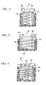
- FIG 4 to FIG. 6 A schematic longitudinal cross-sectional view of the decomposition furnace 33 is shown in FIG 4 to FIG. 6 .
- the decomposition furnace 33 has a cylindrical furnace body 41 and a cylindrical heater 35 surrounding the outer periphery of the cylindrical furnace body 41, and the entire decomposition furnace 33 is accommodated inside a cylindrical vessel 36 that is formed by an insulating material.
- the furnace body 41 is sealed by a lid 37, and a supply pipe 38 (supply device) that supplies a mixed liquid containing polymers and hydrogen chloride into the furnace and a discharge pipe 39 (gas exhaust device) that discharges the produced gas to the outside of the furnace are provided.
- a thermometer 40 is installed in the furnace body 41.
- the supply pipe 38 passing through the lid 37 is provided so as to extend to the inside of the furnace body 41.
- the supply pipe 38 has a spiral shape, and the distal end opening thereof is positioned near the bottom of the decomposition furnace 33.
- the portion of the supply pipe 38 that extends into the furnace is not limited to a spiral shape, but may also have, for example, a meandering (serpentine) shape.
- the TCS generating reaction progresses and the recovery rate for the TCS can thereby be increased. Note that if the mixture containing polymers and hydrogen chloride is preheated before being supplied to the decomposition furnace, there is a possibility that the polymers will remain inside the preheated portion of the pipe.
- the supply pipe 38 is provided with a spiral shape so as to surround the outer periphery of the furnace body 41, and the lower end of the supply pipe 38 opens at the bottom portion of the furnace. According to this structure, there is an advantage in that because the spiral portion of the supply pipe 38 is close to the heater 35, the pre-heating effect is significant.
- the decomposition furnace 33 shown in FIG. 6 has a structure in which the polymer containing liquid and the hydrogen chloride are supplied into the decomposition furnace by passing through separate supply pipes.
- the polymer containing liquid is supplied into the furnace through the supply pipe 38A
- the hydrogen chloride is supplied into the furnace through the supply pipe 38B.
- the polymer containing liquid and the hydrogen chloride are mixed inside the furnace.
- the expression stating that the polymers and the hydrogen chloride are mixed and then introduced into the decomposition furnace, as shown in FIG. 6 also includes the case in which they are supplied into the furnace through separate supply pipes are mixed inside the furnace.
- the supply pipe 38A through which the polymer containing liquid flows, extends into the furnace by meandering in a spiral shape as shown in the figure, the polymer containing liquid is preheated while flowing through the supply pipe 38A into the furnace, the hydrogen chloride is preheated while flowing through the supply pipe 38B inside the furnace, and thus the reaction efficiency can thereby be increased.
- the polymers and the hydrogen chloride are not mixed during the pre-heat, they do not react with each other during pre-heat, and thus there is no concern that shortcomings such as the reactants adhering to and obstructing the inside of the pipes will occur.
- the polymers that have been separated in the chlorination step and the distillation step for the exhaust gas in the reactor are introduced into the polymer decomposition step shown in FIG. 2 .
- the polymers are mixed with hydrogen chloride gas and introduced into the decomposition furnace shown in FIG. 3 , and they are heated to a temperature of 450°C or more and 700°C or less and reacted to produce TCS.
- TABLE 1 and TABLE 2 show the composition of the polymers before being mixed with the hydrogen chloride, the composition (%) of the decomposed gas that is extracted from the decomposing furnace, the decomposition temperature, and the amount of the polymers and the hydrogen chloride.
- the numerical values for the mass% in the tables are values that have been calculated based on the area%.
- after decomposition denotes the composition of the gas that has been extracted from the decomposition furnace.
- the Comparative Example 1 is an example in which the decomposition temperature (300°C) is lower than the range of the present invention
- Example 9 is an example in which the decomposition temperature (900°C) is higher than the preferred range of the present invention
- Example 10 is an example in which the supply rate (6 g/min) of the hydrogen chloride is lower than the preferred range of the present invention.
- the polymers are decomposed to produce TCS in a manner similar to Examples 1 to 3. These results are shown in TABLE 3.
- EXAMPLE 9 EXAMPLE 10 AFTER DECOMPOSITION AFTER DECOMPOSITION AFTER DECOMPOSITION MASS% MASS% MASS% SiH 2 Cl 2 0.1 0.1 0.1 0.2 SiHCl 3 1.0 2.0 12.9 17.9 SiCl 4 58.8 60.9 85.0 75.5 Si 2 H 2 Cl 4 15.6 14.1 0.3 0.4 Si 2 Cl 6 20.6 19.5 0.2 1.0 OTHERS 3.9 3.4 1.5 5.0 POLYMER INPUT AMOUNT - 200g/min 200g/min 200g/min HCl GAS INPUT AMOUNT - 40g/min 40g/min 6g/min DECOMPOSITION FURNACE TEMPERATURE - 300°C 900°C 520°C PRECIPITATION - SMALL AMOUNT SMALL AMOUNT LARGE AMOUNT (OPERATION SUSPENDED) (Note) The expression "before decomposition" denotes the composition of the polymer containing liquid
- after decomposition denotes the composition of the gas that has been extracted from the decomposition furnace.
Landscapes
- Chemical & Material Sciences (AREA)
- Organic Chemistry (AREA)
- Chemical Kinetics & Catalysis (AREA)
- Inorganic Chemistry (AREA)
- Silicon Compounds (AREA)
Applications Claiming Priority (2)
| Application Number | Priority Date | Filing Date | Title |
|---|---|---|---|
| JP2008049229 | 2008-02-29 | ||
| EP09153800.9A EP2096082B1 (de) | 2008-02-29 | 2009-02-26 | Verfahren zur Herstellung von Trichlorsilan |
Related Parent Applications (3)
| Application Number | Title | Priority Date | Filing Date |
|---|---|---|---|
| EP09153800.9 Division | 2009-02-26 | ||
| EP09153800.9A Division-Into EP2096082B1 (de) | 2008-02-29 | 2009-02-26 | Verfahren zur Herstellung von Trichlorsilan |
| EP09153800.9A Division EP2096082B1 (de) | 2008-02-29 | 2009-02-26 | Verfahren zur Herstellung von Trichlorsilan |
Publications (3)
| Publication Number | Publication Date |
|---|---|
| EP2354090A2 true EP2354090A2 (de) | 2011-08-10 |
| EP2354090A3 EP2354090A3 (de) | 2012-08-08 |
| EP2354090B1 EP2354090B1 (de) | 2018-03-28 |
Family
ID=40547415
Family Applications (2)
| Application Number | Title | Priority Date | Filing Date |
|---|---|---|---|
| EP09153800.9A Active EP2096082B1 (de) | 2008-02-29 | 2009-02-26 | Verfahren zur Herstellung von Trichlorsilan |
| EP11164834.1A Ceased EP2354090B1 (de) | 2008-02-29 | 2009-02-26 | Verfahren zur herstellung von trichlorsilan |
Family Applications Before (1)
| Application Number | Title | Priority Date | Filing Date |
|---|---|---|---|
| EP09153800.9A Active EP2096082B1 (de) | 2008-02-29 | 2009-02-26 | Verfahren zur Herstellung von Trichlorsilan |
Country Status (5)
| Country | Link |
|---|---|
| US (1) | US9533279B2 (de) |
| EP (2) | EP2096082B1 (de) |
| JP (1) | JP5621957B2 (de) |
| KR (1) | KR101573933B1 (de) |
| CN (1) | CN101519205B (de) |
Families Citing this family (20)
| Publication number | Priority date | Publication date | Assignee | Title |
|---|---|---|---|---|
| JP5316291B2 (ja) | 2008-08-05 | 2013-10-16 | 三菱マテリアル株式会社 | トリクロロシラン製造装置及び製造方法 |
| JP5316290B2 (ja) | 2008-08-05 | 2013-10-16 | 三菱マテリアル株式会社 | トリクロロシラン製造装置及び製造方法 |
| JP5321314B2 (ja) * | 2009-07-23 | 2013-10-23 | 三菱マテリアル株式会社 | クロロシラン重合物の分解方法および分解装置 |
| DE102009056437B4 (de) | 2009-12-02 | 2013-06-27 | Spawnt Private S.À.R.L. | Verfahren und Vorrichtung zur Herstellung von kurzkettigen halogenierten Polysilanen |
| JP5482265B2 (ja) * | 2009-12-15 | 2014-05-07 | 三菱マテリアル株式会社 | トリクロロシラン製造装置 |
| JP5630412B2 (ja) * | 2010-09-28 | 2014-11-26 | 三菱マテリアル株式会社 | トリクロロシラン製造装置及び製造方法 |
| DE102010043646A1 (de) * | 2010-11-09 | 2012-05-10 | Evonik Degussa Gmbh | Verfahren zur Herstellung von Trichlorsilan |
| DE102010043648A1 (de) * | 2010-11-09 | 2012-05-10 | Evonik Degussa Gmbh | Verfahren zur selektiven Spaltung höherer Silane |
| US8226920B1 (en) * | 2011-01-07 | 2012-07-24 | Mitsubishi Polycrystalline Silicon America Corporation (MIPSA) | Apparatus and method for producing polycrystalline silicon having a reduced amount of boron compounds by venting the system with an inert gas |
| DE102011110040B4 (de) * | 2011-04-14 | 2024-07-11 | Evonik Operations Gmbh | Verfahren zur Herstellung von Chlorsilanen mittels hochsiedender Chlorsilane oder chlorsilanhaltiger Gemische |
| JP2013103872A (ja) * | 2011-11-16 | 2013-05-30 | Yamaguchi Univ | 廃シリコンからのハロシランの製造方法 |
| CN102530960B (zh) * | 2011-12-31 | 2013-08-14 | 中国天辰工程有限公司 | 一种多晶硅生产中的三氯氢硅生产方法 |
| JP5818012B2 (ja) * | 2012-03-29 | 2015-11-18 | 三菱マテリアル株式会社 | クロロシラン重合物の分解方法 |
| DE102012216356A1 (de) * | 2012-09-14 | 2014-03-20 | Evonik Industries Ag | Verfahren zur Herstellung von Chlorsilanen mittels hochsiedender Chlorsilane oder chlorsilanhaltiger Gemische |
| CN103723734B (zh) * | 2012-10-10 | 2015-09-09 | 浙江昱辉阳光能源有限公司 | 一种制备三氯氢硅的工艺 |
| CN102923715A (zh) * | 2012-11-20 | 2013-02-13 | 天威四川硅业有限责任公司 | 一种回收多晶硅生产所产生的尾气的新工艺 |
| JP6486049B2 (ja) | 2014-09-25 | 2019-03-20 | デンカ株式会社 | ペンタクロロジシランの製造方法並びに該方法により製造されるペンタクロロジシラン |
| CN106395832B (zh) * | 2015-08-03 | 2018-11-20 | 新特能源股份有限公司 | 一种四氯化硅氢化方法 |
| CN105060298B (zh) * | 2015-08-12 | 2017-11-07 | 四川永祥多晶硅有限公司 | 一种多晶硅生产中高沸物制备有机硅的处理方法和装置 |
| DE112020005549T5 (de) * | 2019-11-13 | 2022-08-25 | Tokuyama Corporation | Verfahren zur Dehydratisierung von Chlorwasserstoff |
Citations (4)
| Publication number | Priority date | Publication date | Assignee | Title |
|---|---|---|---|---|
| JPH01188414A (ja) | 1988-01-21 | 1989-07-27 | Osaka Titanium Co Ltd | 多結晶シリコンの製造におけるポリマーのトリクロロシラン転化方法 |
| WO2002012122A1 (en) | 2000-08-02 | 2002-02-14 | Mitsubishi Materials Polycrystalline Silicon Corporation | Process for producing disilicon hexachloride |
| US20020183537A1 (en) | 2001-05-31 | 2002-12-05 | Wacker-Chemie Gmbh | Process for preparing silanes |
| US20040131528A1 (en) | 2001-06-08 | 2004-07-08 | Kendig James Edward | Process for preparation of polycrystalline silicon |
Family Cites Families (20)
| Publication number | Priority date | Publication date | Assignee | Title |
|---|---|---|---|---|
| US3607125A (en) * | 1968-12-30 | 1971-09-21 | Gen Electric | Reformer tube construction |
| CH521400A (de) | 1969-01-24 | 1972-04-15 | Inventa Ag | Verfahren und Vorrichtung zur kontinuierlichen Herstellung von Polylactamen |
| BE795913A (fr) | 1972-02-26 | 1973-06-18 | Degussa | Procede de preparation de chlorosilanes |
| US3878234A (en) * | 1973-07-30 | 1975-04-15 | Dow Corning | Preparation of hydrocarbon silanes from polysilanes |
| US4244935A (en) * | 1978-04-20 | 1981-01-13 | Aluminum Company Of America | Method of forming metal chlorides |
| US4321246A (en) * | 1980-05-09 | 1982-03-23 | Motorola, Inc. | Polycrystalline silicon production |
| US4900531A (en) | 1982-06-22 | 1990-02-13 | Harry Levin | Converting a carbon preform object to a silicon carbide object |
| US4526769A (en) * | 1983-07-18 | 1985-07-02 | Motorola, Inc. | Trichlorosilane production process |
| US5118485A (en) * | 1988-03-25 | 1992-06-02 | Hemlock Semiconductor Corporation | Recovery of lower-boiling silanes in a cvd process |
| US5118486A (en) * | 1991-04-26 | 1992-06-02 | Hemlock Semiconductor Corporation | Separation by atomization of by-product stream into particulate silicon and silanes |
| US5292912A (en) * | 1993-07-19 | 1994-03-08 | Dow Corning Corporation | Catalytic conversion of direct process high-boiling component to chlorosilane monomers in the presence of hydrogen chloride |
| DE19654154A1 (de) * | 1995-12-25 | 1997-06-26 | Tokuyama Corp | Verfahren zur Herstellung von Trichlorsilan |
| DE10039172C1 (de) | 2000-08-10 | 2001-09-13 | Wacker Chemie Gmbh | Verfahren zum Aufarbeiten von Rückständen der Direktsynthese von Organochlorsilanen |
| US20020187096A1 (en) * | 2001-06-08 | 2002-12-12 | Kendig James Edward | Process for preparation of polycrystalline silicon |
| JP4038110B2 (ja) | 2001-10-19 | 2008-01-23 | 株式会社トクヤマ | シリコンの製造方法 |
| DE10309799A1 (de) * | 2003-03-05 | 2004-09-23 | Sgl Acotec Gmbh | Verfahren und Vorrichtung zur Herstellung von Chlorwasserstoff |
| NO321276B1 (no) * | 2003-07-07 | 2006-04-18 | Elkem Materials | Fremgangsmate for fremstilling av triklorsilan og silisium for bruk ved fremstilling av triklorsilan |
| DE102005005044A1 (de) | 2005-02-03 | 2006-08-10 | Consortium für elektrochemische Industrie GmbH | Verfahren zur Herstellung von Trichlorsilan mittels thermischer Hydrierung von Siliciumtetrachlorid |
| DE102006009954A1 (de) * | 2006-03-03 | 2007-09-06 | Wacker Chemie Ag | Wiederverwertung von hochsiedenden Verbindungen innerhalb eines Chlorsilanverbundes |
| KR101538168B1 (ko) * | 2007-11-30 | 2015-07-20 | 미쓰비시 마테리알 가부시키가이샤 | 전환 반응 가스의 분리 회수 방법 |
-
2009
- 2009-02-25 KR KR1020090015858A patent/KR101573933B1/ko active Active
- 2009-02-26 JP JP2009044930A patent/JP5621957B2/ja active Active
- 2009-02-26 EP EP09153800.9A patent/EP2096082B1/de active Active
- 2009-02-26 EP EP11164834.1A patent/EP2354090B1/de not_active Ceased
- 2009-02-26 CN CN2009100083323A patent/CN101519205B/zh active Active
- 2009-02-26 US US12/379,702 patent/US9533279B2/en not_active Expired - Fee Related
Patent Citations (4)
| Publication number | Priority date | Publication date | Assignee | Title |
|---|---|---|---|---|
| JPH01188414A (ja) | 1988-01-21 | 1989-07-27 | Osaka Titanium Co Ltd | 多結晶シリコンの製造におけるポリマーのトリクロロシラン転化方法 |
| WO2002012122A1 (en) | 2000-08-02 | 2002-02-14 | Mitsubishi Materials Polycrystalline Silicon Corporation | Process for producing disilicon hexachloride |
| US20020183537A1 (en) | 2001-05-31 | 2002-12-05 | Wacker-Chemie Gmbh | Process for preparing silanes |
| US20040131528A1 (en) | 2001-06-08 | 2004-07-08 | Kendig James Edward | Process for preparation of polycrystalline silicon |
Also Published As
| Publication number | Publication date |
|---|---|
| CN101519205A (zh) | 2009-09-02 |
| CN101519205B (zh) | 2013-09-25 |
| EP2096082B1 (de) | 2018-10-17 |
| KR20090093842A (ko) | 2009-09-02 |
| JP5621957B2 (ja) | 2014-11-12 |
| JP2009227577A (ja) | 2009-10-08 |
| EP2354090B1 (de) | 2018-03-28 |
| US9533279B2 (en) | 2017-01-03 |
| EP2096082A1 (de) | 2009-09-02 |
| EP2354090A3 (de) | 2012-08-08 |
| US20090220403A1 (en) | 2009-09-03 |
| KR101573933B1 (ko) | 2015-12-02 |
Similar Documents
| Publication | Publication Date | Title |
|---|---|---|
| EP2354090B1 (de) | Verfahren zur herstellung von trichlorsilan | |
| EP1437327B1 (de) | Verfahren zur herstellung von silicium | |
| JP5374091B2 (ja) | 多結晶シリコンの製造方法 | |
| EP1264798B1 (de) | Verfahren zur herstellung von disiliciumhexachlorid | |
| EP2085359B1 (de) | Verfahren zur herstellung von trichlorsilan | |
| TWI474976B (zh) | 在涉及歧化操作之實質上封閉迴路方法中之多晶矽製造 | |
| EP2070871B1 (de) | Verfahren zur herstellung von multikristallinem silicium und anlage zur herstellung von multikristallinem silicium | |
| JPS63367B2 (de) | ||
| US20090060819A1 (en) | Process for producing trichlorosilane | |
| JPWO2002012122A1 (ja) | 六塩化二珪素の製造方法 | |
| CN103153855A (zh) | 在基本闭环的方法和系统中制备多晶硅 | |
| KR101392944B1 (ko) | 사염화실란으로부터 삼염화실란을 제조하는 방법 및 이에 사용되는 트리클 베드 반응기 | |
| WO2009029794A1 (en) | Process for producing trichlorosilane | |
| CN102196995B (zh) | 三氯硅烷的制备方法及利用方法 | |
| JPH02172811A (ja) | トリクロロシランの製造方法 | |
| CN105939965B (zh) | 金属硅化物的表面改性方法、利用表面改性的金属硅化物的三氯硅烷的制备方法及装置 | |
| JP7595232B1 (ja) | クロロシラン類の製造方法 | |
| WO2024252911A1 (ja) | クロロシラン類の製造方法 | |
| WO2014008271A1 (en) | Method of recovering elemental metal from polycrystalline semiconductor production |
Legal Events
| Date | Code | Title | Description |
|---|---|---|---|
| PUAI | Public reference made under article 153(3) epc to a published international application that has entered the european phase |
Free format text: ORIGINAL CODE: 0009012 |
|
| AC | Divisional application: reference to earlier application |
Ref document number: 2096082 Country of ref document: EP Kind code of ref document: P |
|
| AK | Designated contracting states |
Kind code of ref document: A2 Designated state(s): DE IT |
|
| REG | Reference to a national code |
Ref country code: DE Ref legal event code: R079 Ref document number: 602009051558 Country of ref document: DE Free format text: PREVIOUS MAIN CLASS: C01B0033100000 Ipc: C01B0033107000 |
|
| PUAL | Search report despatched |
Free format text: ORIGINAL CODE: 0009013 |
|
| AK | Designated contracting states |
Kind code of ref document: A3 Designated state(s): DE IT |
|
| RIC1 | Information provided on ipc code assigned before grant |
Ipc: B01J 19/00 20060101ALI20120629BHEP Ipc: C01B 33/107 20060101AFI20120629BHEP Ipc: B01J 19/24 20060101ALI20120629BHEP |
|
| 17P | Request for examination filed |
Effective date: 20130208 |
|
| 17Q | First examination report despatched |
Effective date: 20130618 |
|
| GRAP | Despatch of communication of intention to grant a patent |
Free format text: ORIGINAL CODE: EPIDOSNIGR1 |
|
| STAA | Information on the status of an ep patent application or granted ep patent |
Free format text: STATUS: GRANT OF PATENT IS INTENDED |
|
| INTG | Intention to grant announced |
Effective date: 20171115 |
|
| RIN1 | Information on inventor provided before grant (corrected) |
Inventor name: TAKESUE, HISAYUKI Inventor name: SATOH, HARUMI Inventor name: TACHINO, NOBORU |
|
| GRAS | Grant fee paid |
Free format text: ORIGINAL CODE: EPIDOSNIGR3 |
|
| GRAA | (expected) grant |
Free format text: ORIGINAL CODE: 0009210 |
|
| STAA | Information on the status of an ep patent application or granted ep patent |
Free format text: STATUS: THE PATENT HAS BEEN GRANTED |
|
| AC | Divisional application: reference to earlier application |
Ref document number: 2096082 Country of ref document: EP Kind code of ref document: P |
|
| AK | Designated contracting states |
Kind code of ref document: B1 Designated state(s): DE IT |
|
| REG | Reference to a national code |
Ref country code: DE Ref legal event code: R096 Ref document number: 602009051558 Country of ref document: DE |
|
| REG | Reference to a national code |
Ref country code: DE Ref legal event code: R097 Ref document number: 602009051558 Country of ref document: DE |
|
| PLBE | No opposition filed within time limit |
Free format text: ORIGINAL CODE: 0009261 |
|
| STAA | Information on the status of an ep patent application or granted ep patent |
Free format text: STATUS: NO OPPOSITION FILED WITHIN TIME LIMIT |
|
| 26N | No opposition filed |
Effective date: 20190103 |
|
| REG | Reference to a national code |
Ref country code: DE Ref legal event code: R081 Ref document number: 602009051558 Country of ref document: DE Owner name: HIGH-PURITY SILICON CORP., YOKKAICHI-SHI, JP Free format text: FORMER OWNER: MITSUBISHI MATERIALS CORPORATION, TOKYO, JP |
|
| PGFP | Annual fee paid to national office [announced via postgrant information from national office to epo] |
Ref country code: DE Payment date: 20240219 Year of fee payment: 16 |
|
| PGFP | Annual fee paid to national office [announced via postgrant information from national office to epo] |
Ref country code: IT Payment date: 20240228 Year of fee payment: 16 |
|
| REG | Reference to a national code |
Ref country code: DE Ref legal event code: R119 Ref document number: 602009051558 Country of ref document: DE |
|
| PG25 | Lapsed in a contracting state [announced via postgrant information from national office to epo] |
Ref country code: DE Free format text: LAPSE BECAUSE OF NON-PAYMENT OF DUE FEES Effective date: 20250902 |
|
| PG25 | Lapsed in a contracting state [announced via postgrant information from national office to epo] |
Ref country code: IT Free format text: LAPSE BECAUSE OF NON-PAYMENT OF DUE FEES Effective date: 20250226 |